EP3228578B1 - Dispositif de treuil électrique et grue mobile - Google Patents
Dispositif de treuil électrique et grue mobile Download PDFInfo
- Publication number
- EP3228578B1 EP3228578B1 EP15866011.8A EP15866011A EP3228578B1 EP 3228578 B1 EP3228578 B1 EP 3228578B1 EP 15866011 A EP15866011 A EP 15866011A EP 3228578 B1 EP3228578 B1 EP 3228578B1
- Authority
- EP
- European Patent Office
- Prior art keywords
- drum
- winch drum
- winch
- motors
- motor
- Prior art date
- Legal status (The legal status is an assumption and is not a legal conclusion. Google has not performed a legal analysis and makes no representation as to the accuracy of the status listed.)
- Active
Links
- 230000007246 mechanism Effects 0.000 claims description 57
- 239000003638 chemical reducing agent Substances 0.000 claims description 56
- 230000005540 biological transmission Effects 0.000 claims description 25
- 230000001965 increasing effect Effects 0.000 claims description 10
- 238000004804 winding Methods 0.000 claims description 6
- 230000004048 modification Effects 0.000 description 31
- 238000012986 modification Methods 0.000 description 31
- 230000000712 assembly Effects 0.000 description 7
- 238000000429 assembly Methods 0.000 description 7
- 238000001816 cooling Methods 0.000 description 6
- 230000004044 response Effects 0.000 description 6
- 230000004323 axial length Effects 0.000 description 5
- 230000004913 activation Effects 0.000 description 3
- 230000001276 controlling effect Effects 0.000 description 3
- 230000009194 climbing Effects 0.000 description 2
- 238000010586 diagram Methods 0.000 description 2
- 230000002452 interceptive effect Effects 0.000 description 2
- 230000009467 reduction Effects 0.000 description 2
- 230000000717 retained effect Effects 0.000 description 2
- 230000008901 benefit Effects 0.000 description 1
- 238000010276 construction Methods 0.000 description 1
- 230000003247 decreasing effect Effects 0.000 description 1
- 230000001419 dependent effect Effects 0.000 description 1
- 238000011161 development Methods 0.000 description 1
- 230000018109 developmental process Effects 0.000 description 1
- 230000000694 effects Effects 0.000 description 1
- 230000001105 regulatory effect Effects 0.000 description 1
Images





Classifications
-
- B—PERFORMING OPERATIONS; TRANSPORTING
- B66—HOISTING; LIFTING; HAULING
- B66D—CAPSTANS; WINCHES; TACKLES, e.g. PULLEY BLOCKS; HOISTS
- B66D1/00—Rope, cable, or chain winding mechanisms; Capstans
- B66D1/02—Driving gear
- B66D1/12—Driving gear incorporating electric motors
-
- B—PERFORMING OPERATIONS; TRANSPORTING
- B66—HOISTING; LIFTING; HAULING
- B66D—CAPSTANS; WINCHES; TACKLES, e.g. PULLEY BLOCKS; HOISTS
- B66D1/00—Rope, cable, or chain winding mechanisms; Capstans
- B66D1/02—Driving gear
- B66D1/14—Power transmissions between power sources and drums or barrels
- B66D1/16—Power transmissions between power sources and drums or barrels the drums or barrels being freely rotatable, e.g. having a clutch activated independently of a brake
-
- F—MECHANICAL ENGINEERING; LIGHTING; HEATING; WEAPONS; BLASTING
- F16—ENGINEERING ELEMENTS AND UNITS; GENERAL MEASURES FOR PRODUCING AND MAINTAINING EFFECTIVE FUNCTIONING OF MACHINES OR INSTALLATIONS; THERMAL INSULATION IN GENERAL
- F16H—GEARING
- F16H1/00—Toothed gearings for conveying rotary motion
- F16H1/02—Toothed gearings for conveying rotary motion without gears having orbital motion
- F16H1/20—Toothed gearings for conveying rotary motion without gears having orbital motion involving more than two intermeshing members
-
- F—MECHANICAL ENGINEERING; LIGHTING; HEATING; WEAPONS; BLASTING
- F16—ENGINEERING ELEMENTS AND UNITS; GENERAL MEASURES FOR PRODUCING AND MAINTAINING EFFECTIVE FUNCTIONING OF MACHINES OR INSTALLATIONS; THERMAL INSULATION IN GENERAL
- F16H—GEARING
- F16H1/00—Toothed gearings for conveying rotary motion
- F16H1/02—Toothed gearings for conveying rotary motion without gears having orbital motion
- F16H1/20—Toothed gearings for conveying rotary motion without gears having orbital motion involving more than two intermeshing members
- F16H1/22—Toothed gearings for conveying rotary motion without gears having orbital motion involving more than two intermeshing members with a plurality of driving or driven shafts; with arrangements for dividing torque between two or more intermediate shafts
-
- B—PERFORMING OPERATIONS; TRANSPORTING
- B66—HOISTING; LIFTING; HAULING
- B66C—CRANES; LOAD-ENGAGING ELEMENTS OR DEVICES FOR CRANES, CAPSTANS, WINCHES, OR TACKLES
- B66C23/00—Cranes comprising essentially a beam, boom, or triangular structure acting as a cantilever and mounted for translatory of swinging movements in vertical or horizontal planes or a combination of such movements, e.g. jib-cranes, derricks, tower cranes
- B66C23/18—Cranes comprising essentially a beam, boom, or triangular structure acting as a cantilever and mounted for translatory of swinging movements in vertical or horizontal planes or a combination of such movements, e.g. jib-cranes, derricks, tower cranes specially adapted for use in particular purposes
- B66C23/36—Cranes comprising essentially a beam, boom, or triangular structure acting as a cantilever and mounted for translatory of swinging movements in vertical or horizontal planes or a combination of such movements, e.g. jib-cranes, derricks, tower cranes specially adapted for use in particular purposes mounted on road or rail vehicles; Manually-movable jib-cranes for use in workshops; Floating cranes
-
- B—PERFORMING OPERATIONS; TRANSPORTING
- B66—HOISTING; LIFTING; HAULING
- B66C—CRANES; LOAD-ENGAGING ELEMENTS OR DEVICES FOR CRANES, CAPSTANS, WINCHES, OR TACKLES
- B66C2700/00—Cranes
- B66C2700/03—Cranes with arms or jibs; Multiple cranes
- B66C2700/0321—Travelling cranes
- B66C2700/0357—Cranes on road or off-road vehicles, on trailers or towed vehicles; Cranes on wheels or crane-trucks
- B66C2700/0364—Cranes on road or off-road vehicles, on trailers or towed vehicles; Cranes on wheels or crane-trucks with a slewing arm
- B66C2700/0371—Cranes on road or off-road vehicles, on trailers or towed vehicles; Cranes on wheels or crane-trucks with a slewing arm on a turntable
Definitions
- the present invention relates to an electric winch device and a mobile crane.
- a mobile crane is mounted with a winch device driven by a hydraulic actuator such as a hydraulic motor to perform a hoisting work of raising or lowering a hoisted load by the winch device.
- a hydraulic actuator such as a hydraulic motor to perform a hoisting work of raising or lowering a hoisted load by the winch device.
- Patent Literature 1 shows a climbing crane as an example of the tower crane.
- the climbing crane disclosed in Patent Literature 1 includes an electric winch device having a winch drum and two motors to drive the drum.
- the two motors are arranged on the opposite sides of the winch drum in an axial direction of the winch drum in order to prevent occurrence of a twist at a local portion of an input shaft or a body of the winch drum, and torques are input from the respective motors on the opposite sides to the winch drum.
- Patent Literature 1 Although the electric winch device of Patent Literature 1 has an advantage that a sufficient hoisting performance can be assured by rotating the winch drum by a torque output from the two motors, it is difficult to mount the electric winch device on a mobile crane in terms of a dimensional restriction for the mobile crane. The reason for the difficulty will be described below.
- a winch device is mounted on an upper slewing body.
- the upper slewing body will involve a dimensional limitation when the upper slewing body is transported or the mobile crane runs on a public road.
- the upper slewing body is placed in a transportation vehicle such as a trailer for transportation of the mobile crane.
- the upper slewing body is placed in such manner that the width direction of the upper slewing body is along the width direction of the transportation vehicle.
- the transportation vehicle runs on a public road, and hence is required to satisfy a statutory regulated vehicle width restriction. Accordingly, the width of the upper slewing body is also limited in accordance with the vehicle width restriction.
- the electric winch device has an increased dimension in the axial direction of the winch drum. Therefore, it is difficult to mount the electric winch device on the upper slewing body because of the above-described width limitation of the upper slewing body.
- the mobile crane when a mobile crane runs on a public road, the mobile crane is required to satisfy the vehicle width restriction.
- the upper slewing body is arranged in such a manner that the width direction of the upper slewing body is along the vehicle width direction of the mobile crane, when the mobile crane runs on a public road.
- the width of the upper slewing body is limited in accordance with the vehicle width restriction in this case as well. Therefore, it is also difficult to mount the electric winch device of Patent Literature 1 on the upper slewing body.
- Patent Literature 2 discloses a similar electric winch device.
- Patent Literature 3 discloses that, in a free fall, a free fall speed increasing signal is sent to a parking control valve from a controller by ON of a changeover switch operated by a pedal, and the free fall speed increasing action is provided by lowering and rotating a hydraulic motor by operating the valve. At this time, a lowering speed is changed in response to an operation quantity of a brake pedal.
- Patent Literature 4 relates to a similar electric winch device in which each motor is respectively connected to a speed reducer outside of the drum.
- Patent literature 5 discloses a skip hoist with the features of the preamble of claim 1.
- An object of the present invention is to provide an electric winch device and a mobile crane which can assure a sufficient hoisting performance and satisfy the dimensional restriction for the mobile crane.
- An electric winch device is an electric winch device which is to be mounted on a mobile crane including an operative part for hoisting work to cause the operative part to perform an operation for the hoisting work by winding up or letting out a rope connected to the operative part, the electric winch device comprising: a winch drum having an axis, the winch drum being provided on the mobile crane to be rotatable about the axis and being wound with the rope therearound; a plurality of motors located on one side of the winch drum in an axial direction in which the axis of the winch drum extends, and arranged side by side in a direction perpendicular to the axial direction of the winch drum; a gear mechanism which combines torques output from the plurality of motors; and a transmitting part which transmits a resultant of torques combined by the gear mechanism to the winch drum to rotate the winch drum to thereby cause the winch drum to wind up or let out the rope wherein each of the plurality of motors
- a mobile crane according to another aspect of the present invention includes the electric winch device according to the one aspect.
- FIGS. 1 to 4 An electric winch device 1 according to a first embodiment of the present invention and a mobile crane including the same will be described with reference to FIGS. 1 to 4 .
- FIG. 1 illustrates an exemplary mobile crane which is mounted with the electric winch device 1 according to the first embodiment 1.
- the mobile crane is a crawler crane.
- the mobile crane includes a lower travelling body 2 of the self-running crawler type, and an upper slewing body 4 mounted on the lower travelling body 2.
- the upper slewing body 4 includes a slewing frame 6, a boom 8, and a hook device 12.
- the slewing frame 6 is mounted on the lower traveling body 2 slewably about a vertical axis.
- the boom 8 is attached to a front portion of the slewing frame 6 and movable up and down.
- the hook device 12 is hanged from the top end of the boom 8 via a hoist rope 10 made of wires to hang a hoisted load 100.
- the hook device 12 is an example of the operative part for hoisting work according to the present invention.
- the hook device 12 and the hoisted load 100 are combinedly referred to as a target object 102 to be raised and lowered.
- front and rear used in the description respectively mean the “front” and the “rear” of the upper slewing body 4 or the slewing frame 6.
- front side of the slewing body 4 means one side where the boom 8 is located
- rear side of the slewing body 4 means the other side that is opposite to the one side where the boom 8 is located.
- a width direction of the upper slewing body 4 is a direction perpendicular to both a front and rear direction, and an axial direction of a slewing axis of the upper slewing body 4.
- the slewing frame 6 bears a first standing support 14 and a second standing support 16 thereon to support a winch drum 20 to be described later.
- the first standing support 14 and the second standing support 16 are disposed in an intermediate position in the front and rear direction of the slewing frame 6, and behind the attachment position of the boom 8 on the slewing frame 6 (see FIG. 1 ).
- the first standing support 14 and the second standing support 16 face each other at a distance therebetween in the width direction of the slewing frame 6.
- the first standing support 14 has a first base part 14a fixedly attached to the slewing frame 6, and a first bearing part 14b retained by the first base part 14a.
- the second standing support 16 has a second base part 16a fixedly attached to the slewing frame 6, and a second bearing part 16b retained by the second base part 16b.
- the electric winch device 1 is mounted on the upper slewing body 4 (see FIG. 1 ).
- the electric winch device 1 is arranged behind the attachment position of the boom 8 on the slewing frame 6.
- the electric winch device 1 is a winch device for winding which winds up or lets out the hoist rope 10 connected to the hook device 12 to thereby cause the hook device 12 to move upward or downward for the hoisting work.
- the electric winch device 1 includes a winch drum 20 (hereinafter, referred to as "drum 20"), a first motor 22, a second motor 24, a gear mechanism 26, a transmitting part 28, a first brake 30, and a second brake 32.
- the drum 20 is wound with the hoist rope 10 therearound, and is rotated to wind up and let out the hoist rope 10, thereby raising and lowering the hook device 12 ( FIG. 1 ). In other words, the drum 20 is rotated to wind up and let out the hoist rope 10, thereby raising and lowering the target object 102.
- the drum 20 has an axis 20a about which the drum 20 rotates, and is supported by the first standing support 14 and the second standing support 16 in such a manner that an axial direction of the drum 20 in which the axis 20a lies is along the width direction of the upper slewing body 4. In this manner, the drum 20 is provided on the slewing frame 6. As illustrated in FIG.
- the drum 20 has a drum body 40, a first shaft 41, and a second shaft 42. Also, FIG. 2 illustrates a cross sectional view of the drum body 40 and the hoist rope 10 that is taken along the axis of the drum body 40 in order to show an inside of the drum body 40.
- the drum body 40 serves to wind the hoist rope 10 thereon.
- the hoist rope 10 is pulled out from the drum body 40, passes through the top end of the boom 8 (see FIG. 1 ), and extends therefrom to hang the hook device 12.
- the drum body 40 is in the cylindrical shape, and has flanges at the axially opposite ends thereof.
- the axis 20a agrees with an axis of the cylindrical drum body 30.
- the drum body 40 has a space in the inside thereof.
- the first shaft 41 (see FIG. 2 ) is fixedly attached to one axial end of the drum body 40 and rotatable integrally with the drum body 40.
- the first shaft 41 extends outward from the one axial end of the drum body 40, and is coaxial with the drum body 40.
- the second shaft 42 (see FIG. 2 ) is fixedly attached to the other axial end of the drum body 40 and rotatable integrally with the drum body 40.
- the second shaft 42 extends outward from the other axial end of the drum body 40, and is coaxial with the drum body 40.
- the first shaft 41 is rotatably supported by the first bearing part 14b
- the second shaft 42 is rotatably supported by the second bearing part 16b in the state that the drum body 40 is arranged between the first standing support 14 and the second standing support 16.
- the drum 20 is disposed over the upper slewing body 4 of the mobile crane while being rotatable about the axis 20a that is along the width direction of the upper slewing body 4.
- the drum 20 is rotated in a wind-up direction which is one of the rotational directions to wind up the hoist rope 10 on the drum body 40 to thereby raise the hook device 12 (see FIG. 1 ) to raise the target object 102.
- the drum 20 is rotated in a let-out direction which is the opposite rotational direction to the wind-up direction to let out the hoist rope 10 to thereby lower the hook device 12 to lower the target object 102.
- the first motor 22 and the second motor 24 are activated by electric power supply, and output torques to rotate the drum 20 in the wind-up direction to raise the target object 102.
- the first and second motors 22, 24 are located on one side of the drum 20 in the axial direction of the drum 20 over the upper slewing body 4 of the mobile crane.
- the first and second motors 22, 24 are arranged on one side of the first standing support 14, in the axial direction of the drum 20, that is opposite to the other side of the first standing support 14 where the drum body 40 lies.
- the first motor 22 has a first motor body 22a and a first drive shaft 22b.
- the first motor 22a is activated by power supply to thereby cause the first drive shaft 22a to rotate about the axis thereof, and serves as a driving device.
- the first drive shaft 22b rotates owing to the activation of the first motor 22a.
- the first drive shaft 22b is a shaft for outputting the torque generated by the first motor body 22a.
- the first drive shaft 22b serves as an output shaft for the torque of the first motor 22.
- the first motor body 22a is supported by an unillustrated motor support provided on the slewing frame 6 while keeping the first drive shaft 22b lying along the axial direction of the drum 20.
- the first drive shaft 22b has an extension 22c ( FIG. 2 ) protruding from the first motor body 22a toward the first standing support 14.
- the first drive shaft 22b is connected to the gear mechanism 26.
- the second motor 24 has a second motor body 24a and a second drive shaft 24b.
- the second motor body 24a is activated by power supply to thereby cause the second drive shaft 24b to rotate about the axis thereof, and serves as a driving device.
- the second drive shaft 24b rotates owing to the activation of the second electric body 24a.
- the second drive shaft 24b is a shaft for outputting the torque generated by the second electric body 24a.
- the second drive shaft 24b serves as an output shaft for the torque of the second motor 24.
- the second electric motor body 24a is supported by an unillustrated motor support provided on the slewing frame 6 while keeping the second drive shaft 24b lying along the axial direction of the drum 20.
- the second motor 24 is arranged side by side with the first motor 22 in a direction perpendicular to the axial direction of the drum 20 and the second drive shaft 24b extends in parallel to the first drive shaft 22b.
- the second drive shaft 24b has an extension 24c (see FIG. 2 ) protruding from the second motor body 24 toward the first standing support 14.
- the gear mechanism 26 combines the torque output from the first motor 22 and the torque output from the second motor 24. In other words, the gear mechanism 26 combines the torque of the first drive shaft 22b and the torque of the second drive shaft 24b.
- the gear mechanism 26 is arranged between the first and second motors 22, 24, and the first standing support 14. In other words, the gear mechanism 26 is arranged on one side of the first standing support 14, in the axial direction of the drum 20, that is opposite to the other side of the first standing support 14 where the drum body 40 lies.
- the gear mechanism 26 has a center gear 50, a first gear 51, and a second gear 52.
- Each of the gears 50, 51, 52 has external teeth.
- FIGS. 2 and 3 schematically illustrate the gears 50, 51, 52, and thus the external teeth of each of the gears are unillustrated.
- the first shaft 41, the first bearing part 14b and the like of the drum 20 are not fully illustrated from the perspective of easy understanding of the arrangement of the first gear 51 and the second gear 52 with respect to the center gear 50, and a transmission shaft 54 coupled to the center gear 50 to be described later.
- the above-described non-illustration is applied to FIGS. 5 and 7 to 11 which refer to another embodiment and modifications to be described later.
- the center gear 50 is an example of the outputting member according to the present invention.
- the center gear 50 is coaxial with the drum 20.
- the first gear 51 is coaxial with the first drive shaft 22b (see FIG. 2 ), and is coupled thereto to rotate integrally therewith.
- the first gear 51 is coupled to a leading end of the extension 22c of the first drive shaft 22b.
- the second gear 52 is coaxial with the second drive shaft 24b (see FIG. 2 ), and is coupled thereto to rotate integrally therewith.
- the second gear 52 is coupled to a leading end of the extension 24c of the second drive shaft 24b.
- the first gear 51 and the second gear 52 are arranged around the center gear 50. Specifically, the first gear 51 and the second gear 52 are arranged on radially one outside and radially the opposite outside of the center gear 50. The first gear 51 and the second gear 52 mesh with the center gear 50. In this configuration, the torque of the first drive shaft 22b is transmitted from the first gear 51 to the center tear 50, and the torque of the second drive shaft 24b is transmitted from the second gear 52 to the center gear 50. In this manner, the torques of the drive shafts 22b, 24b are combined with each other. In other words, the center gear 50 is rotated owing to a resultant of torques of the drives shafts 22b, 24b that are combined with each other.
- the first gear 51 has the same configuration as the second gear 52.
- Each of the first gear 51 and the second gear 52 has a smaller radius and a smaller number of teeth than the center gear 50.
- the center gear 50 has a lower rotational speed than the first and second gears 51, 52.
- the torque of the center gear 50 corresponds to the resultant of torques from the first and second gears 51, 52 that are combined with each other, and hence is greater than each of the torques from the first and second gears 51, 52. Accordingly, the gear mechanism 26 generates a greater toque than each of the torques of the first and second drive shafts 22, 24b.
- the transmitting part 28 (see FIG. 2 ) transmits the resultant of torques combined by the gear mechanism 26 to the drum 20, thereby rotating the drum 20 to wind up or let out the hoist rope 10. As illustrated in FIG. 2 , the transmitting part 28 has the transmission shaft 54 and a speed reducer 56.
- the transmission shaft 54 extends from the center gear 50 to the inside of the drum body 40 through the first shaft 41.
- the transmission shaft 54 is coaxial with the center gear 50, and integrally rotatable therewith about the same axis. Furthermore, the transmission shaft 54 is coaxial and the drum 20.
- the transmission shaft 54 is rotatable relative to the first shaft 41 of the drum 20.
- the speed reducer 56 is arranged in the inside of the drum body 40.
- the speed reducer 56 has an input portion connected with the transmission shaft 54, and an output portion connected to the drum body 40.
- the speed reducer 56 rotates the drum 20 at a rotational speed to which the rotational speeds of the center gear 50 and the transmission shaft 54 have been reduced at a predetermined speed reduction ratio.
- the speed reducer 56 increases the torque input from the transmission shaft 54.
- the transmitting part 28 increases the torque input from the center gear 50 of the gear mechanism 26 while transmitting the torque to the drum body 40.
- the first brake 30 brakes the rotation of the drum 20 connected to the first drive shaft 22b via the gear mechanism 26 and the transmitting part 28 by applying a braking force to the first drive shaft 22b of the first motor 22.
- an electromagnetic brake constitutes the first brake 30.
- the first brake 30 is arranged closer to the first standing support 14 than the first motor body 22a, i.e., arranged between the first motor body 22a and the gear mechanism 26, and fixedly attached to the first motor body 22a.
- the first brake 30 surrounds the extension 22c of the first drive shaft 22b, and applies the braking force to the extension 22c.
- the second brake 32 brakes the rotation of the drum 20 connected to the second drive shaft 24b via the gear mechanism 26 and the transmitting part 28 by applying a braking force to the second drive shaft 24b of the second motor 24.
- An electromagnetic brake constitutes the second brake 32, like the first brake 30.
- the second brake 32 is arranged closer to the first standing support 14 than the second motor body 24a, i.e., between the second motor body 24a and the gear mechanism 26, and fixedly attached to the second motor body 24a.
- the second brake 32 surrounds the extension 24c of the second drive shaft 24b, and applies the braking force to the extension 24c.
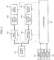
- a control system for controlling the first and second motors 22, 24, and the first and second brakes 30, 32 as shown in FIG. 4 is provided on the mobile crane.
- the control system includes a winch operating device 60, a brake operating device 62, a first inverter 64, a second inverter 66, and a controller 68.
- the winch operating device 60 is used to perform an operation to rotate the drum 20 (see FIG. 2 ) in the wind-up or let-out direction.
- the winch operating device 60 has an unillustrated operative lever, and outputs an instruction signal in response to an operation of the operative lever to the controller 68.
- the brake operating device 62 is used to operate the first brake 30 and the second brake 32.
- the brake operating device 62 has an unillustrated pedal, and outputs an instruction signal in response to an operation of the brake pedal to the controller 68.
- the first inverter 64 controls an electric current supplied from a power source 70 to the first motor body 22a.
- the second inverter 66 controls an electric current supplied from the power source 70 to the second motor body 24a.
- the controller 68 controls the first inverter 64 and the second inverter 66 to cause an electric current in accordance with the instruction signal indicative of the operation of the operative lever to flow into the first motor body 22a and the second motor body 24a. In this manner, the controller 68 controls the activation of the first and second motors 22, 24 in order to rotate the drum 20 in the wind-up or let-out direction in accordance with the operation of the operative lever. Further, in response to the instruction signal input from the brake operating device 62, the controller 68 also controls each of the first and second brakes 30, 32 to apply a braking force in accordance with the instruction signal indicative of an operation of the brake pedal.
- the gear mechanism 26 combines the torque of the first drive shaft 22b of the first motor 22 and the torque of the second drive shaft 24b of the second motor 24, and the transmitting part 28 transmits the resultant of torques combined by the gear mechanism 26 to the winch drum 20. Therefore, it is possible to rotate the drum 20 by a sufficient torque. Accordingly, the electric winch device 1 and the mobile crane including the same can assure a sufficient hoisting performance.
- the first and second motors 22, 24 are arranged on the one side of the drum 20 in the axial direction of the drum 20, and arranged side by side in a direction perpendicular to the axial direction of the drum 20.
- the dimension of the electric winch device 1 in the axial direction of the drum 20 can be reduced in comparison with an assumed case where a first motor 22 and a second motor 24 are arranged on the opposite sides of the drum 20 in the axial direction of the drum 20. Accordingly, when the electric winch device 1 is mounted on the upper slewing body 4 in such a manner that the axial direction of the drum 20 is along with the width direction of the upper slewing body 4, it is possible to satisfy the width limitation of the upper slewing body 4.
- the transmitting part 28 which has the speed reducer 56 makes it possible to rotate the drum 20 at a lower rotational speed than the center gear 50 of the gear mechanism 26. Further, in the first embodiment, the size of the electric winch device 1 can be reduced owing to the arrangement of the speed reducer 56 in the inside of the drum body 40 in comparison with a case where a speed reducer 56 is arranged outside the drum 20.
- the first brake 30 applies the braking force to the first drive shaft 22b of the first electric motor 22, and the second brake 32 applies the braking force to the second shaft 24b of the second motor 24. In this manner, it is possible to brake the rotation of the drum 20.
- the other brake can keep the braking force to brake the rotation of the drum 20. Therefore, it is possible to ensure an increased reliability in the braking of the rotation of the drum 20.
- the first and second brakes 30, 32 can sufficiently brake the rotation of the drum 20 at their respective small braking forces.
- the gear mechanism 26 and the speed reducer 56 transmit the torques of the drive shafts 22b, 24b of the motors 22, 24 to the drum 20 after increments.
- the brakes 30, 32 apply the braking forces to the respective drive shafts 22b, 24b of the motors 22, 24 which are located at a starting position of a torque transmission sequence.
- the brakes 30, 32 can brake the rotation of the drum 20 at smaller braking forces.
- FIG. 5 schematically illustrates a configuration of an electric winch device 1 according to a second embodiment of the present invention.
- FIG. 6 shows a configuration of a control system to control the electric winch device 1 according to the second embodiment.
- the electric winch device 1 according to the second embodiment will be described with reference to FIGS. 5 and 6 .
- the electric winch device 1 according to the second embodiment is to be mounted on a mobile crane, and is used to perform an operation of raising and lowering a target object 102 (see FIG. 1 ) in the same manner as the electric winch device 1 according to the first embodiment.
- the electric winch device 1 according to the second embodiment includes a transmitting part 28 having a clutch 58 (see FIG. 5 ) which is configured to be switched between a connection state and a disconnection state, the connection state being a state where the clutch 58 performs a transmission of a torque between a gear mechanism 26 and a drum 20, specifically between a speed reducer 56 and the drum 20, the disconnection state being a state where the clutch 58 suspends the transmission of the torque therebetween.
- the speed reducer 56 is arranged in an inside of a drum body 40 at a position closer to first and second motors 22, 24 than the speed reducer 56 of the first embodiment.
- This configuration can ensure a sufficient space in the inside of the drum body 40 on one side of the speed reducer 56 that is opposite to the other side of the speed reducer 56 where the first and second electric motors 22, 24 lie, and the space is utilized to place the clutch 58 therein.
- the clutch 58 is arranged on the one side of the speed reducer 56, in the axial direction of the drum 20, that is opposite to the other side of the speed reducer 56 where the first and second motors 22, 24 lies, and arranged in the inside of the drum body 40.
- a wet clutch constitutes the clutch 58.
- the clutch 58 has one clutch plate to rotate integrally with an unillustrated output shaft of the speed reducer 56, the other clutch plate to rotate integrally with the drum body 40, and a switcher which switches over an engagement state where the clutch plates engage with each other, and a disengagement state where the clutch plates disengage from each other.
- the one clutch plate, the other clutch plate, and the switcher of the clutch 58 are unillustrated.
- the clutch 58 switches to a connection state where the clutch 58 performs a torque transmission between the speed reducer 56 and the drum body 40 in accordance with an operation of the switcher to make the clutch plates come into the engagement state.
- the clutch 58 switches to a disconnection state where the clutch 58 suspends the torque transmission between the speed reducer 56 and the drum body 40 by disconnecting the speed reducer 56 from the drum body 40 in accordance with an operation of the switcher to make the clutch plates come into the disengagement state.
- the clutch 58 is controlled by a controller 68 (see FIG. 6 ) of the control system. Specifically, the controller 68 sends a control signal to the switcher of the clutch 58, and the switcher switches over the engagement state and the disengagement state of the clutch plates in response to the control signal.
- the electric winch device 1 according to the second embodiment has the same configuration as the electric winch device 1 of the first embodiment except for the above-described configuration.
- the drum 20 is disconnected from the speed reducer 56, and the gear mechanism 26 and the motors 22, 24 connected thereto, and allowed to freely rotate. As a result, a free fall of the hook device 12 (see FIG. 1 ) is permitted.
- the size of the electric winch device 1 can be reduced owing to the arrangement of the clutch 58 in the inside of the drum body 40 in comparison with a case where a clutch is arranged outside a drum.
- the clutch 58 is arranged on one side of the speed reducer 56, in the axial direction of the drum 20, that is opposite to the other side of the speed reducer 56 where the motors 22, 24 lie.
- a cooling system to cool the clutch 58 and electric cables to the clutch 58 without interfering with an arrangement of a cooling system and electric cables to the motors 22, 24.
- This configuration enables an easy arrangement of the cooling system and electric cables to the clutch 58.
- FIGS. 7 and 8 a modification illustrated in FIGS. 7 and 8 may be appreciated, in which a first brake 30 is arranged on one side of a first motor body 22a that is opposite to the other side of the first motor body 22a where the drum 20 lies, and fixedly attached to the first motor body 22a.
- the first brake 30 is arranged on the one side of the first motor body 22a that is opposite to the other side of the first motor body 22a where a gear mechanism 26 lies, and fixedly attached to the first motor body 22a.
- a first drive shaft 22b protrudes from one end of the first motor body 22a that is opposite to the other end located closer to the gear mechanism 26, whereby permitting the first brake 30 to apply a braking force to the protruded extension of the first drive shaft 22b.
- a second brake 32 may be appreciated to be arranged on one side of a second motor body 24a that is opposite to the other side of the second motor body 24a where the drum 20 lies, and fixedly attached to the second motor body 24a.
- the second brake 32 is arranged on the one side of the second motor body 24a that is opposite to the other side of the second motor body 24a where the gear mechanism 26 lies, and fixedly attached to the second motor body 24a.
- a second drive shaft 24b protrudes from one end of the second drive shaft 24b that is opposite to the other end located closer to the gear mechanism 26, whereby permitting the second brake 32 to apply a braking force to the protruded extension of the second drive shaft 22b.
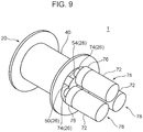
- the number of motors located on one side of a drum in an axial direction of the drum may not be limited to two. Specifically, three or more motors may be located on the one side of the drum in the axial direction thereof.
- FIG. 9 illustrates another modification of the electric winch device 1 that includes three motors 72 arranged on one side of a drum 20 in an axial direction of the drum 20.
- the assemblies 78 each including a motor 72, a gear 74 coupled to a drive shaft of the motor 72 to rotate integrally therewith, and a brake 76 which applies a braking force to the drive shaft.
- the gear 74 in each of the assemblies 78 is meshed with the center gear 50.
- the motor 72 has the same configuration as the first and second motors 22, 24 of the first embodiment
- the gear 74 has the same configuration as the first and second gears 51, 52 of the first embodiment
- the brake 76 has the same configuration as the first and second brakes 30, 32 of the first embodiment.
- four or more assemblies 78 may be arranged around the center gear 50 in the same manner.
- the brake 76 may be arranged on one side of a motor body that is opposite to the other side of the motor body where the drum 20 lies in the same manner as the modification illustrated in FIGS. 7 and 8 .
- a larger number of motors 72 can apply a greater torque to the drum 20.
- all the motors 72 included in the electric winch device 1 are located only on the one side of the drum 20 in the axial direction of the drum 20, and arranged side by side in a direction perpendicular to the axial direction of the drum 20. This configuration makes it possible to prevent an increase in the dimension of the electric winch device 1 in the axial direction of the drum 20, and further satisfy a width limitation of an upper slewing body 4.
- the electric winch device should not be limited to one including motors located only on one side of a drum in an axial direction of the drum.
- an electric winch device 1 includes a first and second motors 22, 24 located on one side of a drum 20, in an axial direction of the drum 20, where a first standing support 14 lies, and additionally a third motor 82 arranged on the other side of the drum 20 in the axial direction of the drum 20, where a second standing support 16 lies.
- the third motor 82 has a third motor body 82a and a third drive shaft 82b, the third motor body 82b being arranged on one side of the second standing support 16, in the axial direction of the drum 20, that is opposite to the other side of the second standing support 16 where the drum 20 lies, and the third drive shaft 82b extending from the third motor body 82a to an inside of a drum body 40 through a second shaft 42.
- the third motor body 82a has the same configuration as the first motor body 22a of the first embodiment.
- the third drive shaft 82b is coaxial with the drum 20.
- the third motor body 82a is provided with a third brake 84 arranged on one side of the third motor body 82a where the second standing support 16 lies.
- the third brake 84 is fixedly attached to the third motor body 82a.
- the third brake 84 applies a braking force to an extension of the third drive shaft 82b that protrudes from the third motor body 82a toward the drum 20.
- the drum body 40 accommodates a first speed reducer 86 and a second speed reducer 88 in the inside thereof, the first speed reducer 86 being provided in a transmitting part 28 which transmits a resultant of torques combined by a gear mechanism 26 to the drum body 40, and the second speed reducer 88 having an input portion connected with the third drive shaft 82b.
- the first speed reducer 86 has the same configuration as the speed reducer 56 of the first embodiment except that the first speed reducer 86 is arranged closer to the first standing support 14 than the speed reducer 56.
- the second speed reducer 88 is arranged side by side with the first speed reducer 86 in the axial direction of the drum 20 in the inside of the drum body 40, and arranged on one side of the first speed reducer 86 where the second standing support 16 lies.
- the second speed reducer 88 has an output portion connected to the drum body 40.
- the second speed reducer 88 rotates the drum body 40, i.e., the drum 20, at a rotational speed to which the rotational speed of the third drive shaft 82b has been reduced at a predetermined speed reduction ratio.
- each of the first and second motor bodies 22a, 24a has a smaller axial length than the first and second motor bodies 22a, 24a of the first embodiment.
- each of the first and second motor bodies 22a, 24 of the modification has a smaller axial length which is around a half of the axial length of the first and second motor bodies 22a, 24a of the first embodiment.
- the arrangement of the third motor 82 and the third brake 84 on the side where the standing support 16 lies may lead to an increased dimension of the electric winch device 1 in the axial direction of the drum 20.
- a motor outputs a torque which is proportional to an axial length of a motor body.
- the first motor 22 of the modification illustrated in FIG. 10 outputs a smaller torque than the first motor 22 of the first embodiment.
- the second motor 24 of the modification outputs a smaller torque than the second motor 24 of the first embodiment.
- the third motor 82 can generate more than the decreased output torques. Therefore, the modification illustrated in FIG. 10 makes it possible to enhance the hoisting performance of the electric winch device 1.
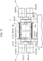
- FIG. 11 may be provided with a first assembly 91 and a second assembly 92 having the same configuration as the first assembly 91.
- the first and second assemblies 91, 92 are symmetrically arranged with each other, specifically on one side of the drum 20, in the axial direction of the drum 20, where the first standing support 14 lies, and on the other side of the drum 20 where the second standing support 16 lies.
- Each of the first and second assemblies 91, 92 includes a first motor 22, a first brake 30, a second motor 24, a second brake 32, a gear mechanism 26, and a transmitting part 28.
- each of the first and second assemblies 91, 92 has the same configuration as the assembly of the modification illustrated in FIG. 10 that includes the first motor 22, the first brake 30, the second motor 24, the second brake 32, the gear mechanism 26, and the transmitting part 28.
- the second assembly 92 arranged on the side where the second standing support 16 lies includes two motor bodies 94a, 96a each having a smaller axial length than the third motor body 82a of the modification illustrated in FIG. 10 .
- this modification makes it possible to reduce the dimension of the electric winch device 1 in the axial direction of the drum 20 in comparison with the modification illustrated in FIG. 10 .
- each of the motors 94, 96 in the second assembly 92 outputs a smaller torque than the third motor 82 of the modification illustrated in FIG. 10 .
- this modification includes a larger number of motors, i.e., the motors, 94, 96, than the modification illustrated in FIG. 10 , and hence can ensure a sufficient torque equivalent to that of the modification illustrated in FIG. 10 or more as a torque to be applied from the second assembly 92 to the drum 20.
- a clutch may not be necessarily provided between a speed reducer and a drum in a transmitting part which performs a torque transmission between a gear mechanism and the drum.
- a clutch may be provided between the gear mechanism and the speed reducer.
- the present invention should not be limited to an electric winch device of the winding type that is operative to perform an operation of raising and lowering a target object.
- the present invention may be applied to an electric winch device of the tilting type that tilts a tilting member such as a boom.
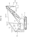
- FIG. 12 schematically illustrates a configuration of a mobile crane mounted with an electric winch device 105 of the tilting type that is a modification of the present invention.
- the mobile crane includes an upper slewing body 4 provided with a gantry 106 standing at a rear portion thereof. Further, the mobile crane includes a tilting device 107 for a hoisting operative section.
- the tilting device 107 includes a boom 8 serving as a tilting member, a mast 108, a guy line 110, a mast spreader 112a, and a gantry spreader 112b.
- the mast 108 is disposed in an intermediate position in the front and rear direction of the upper slewing body 4 and pivotable about an axis extending in the width direction of the upper slewing body 4.
- the guy line 110 connects the top end of the mast 108 and the top end of the boom 8 with each other.
- the mast spreader 112a is provided at a top end of the mast 108, and the gantry spreader 112b is provided at a top end of the gantry 106.
- the electric winch device 105 is arranged at a location close to a base portion of the gantry 106. Specifically, a pair of support base parts 109, which are identical to the first and second base parts 14a, 16a, are attached to the gantry 106 at the location close to the base portion thereof while defining a space therebetween in the width direction of the upper slewing body 4.
- the pair of support base parts 109 respectively retain unillustrated bearing parts, which are identical to the first and second bearing parts 14b, 16b.
- the unillustrated bearing parts rotatably support a shaft of a winch drum 115 (hereinafter, referred to as "drum 115") provided in the electric winch device 105.
- the drum 115 is arranged in such a manner that the axial direction thereof is along the width direction of the upper slewing body 4.
- the drum 115 is wound with a tilt rope 116 therearound.
- the tilt rope 116 pulled out from the drum 115 extends through the gantry spreader 112b and the mast spreader 112a.
- the drum 115 is rotated to wind up and let out the tilt rope 116, thereby causing the tilting device 107 to tilt the boom 8 upward and downward for hoisting work.
- the drum 115 is rotated to wind up the tilt rope 116 and pull the mast spreader 112a toward the gantry spreader 112b, thereby pivotally moving the mast 108 rearward and further pulling the top end of the boom 8 rearward via the guy line 110. In this manner, the boom 8 gradually stands while pivotally moving rearward. Alternately, the drum 115 is rotated to let out the tilt rope 116, thereby allowing the mast spreader 112a to move forward and away from the gantry spreader 112b. In this manner, the boom 8 is pivotally tilted forward with the support of the mast 108 via the guy line 110.
- the electric winch device 105 of the tilting type has the same configuration as the electric winch device 1 except for the above-described configuration. Hence, this modification also can bring about the same advantageous effect as the electric winch device 1.
- the present invention should not be limited to a mobile crane of the crawler type.
- the present invention is applicable to a wheel crane having a lower travelling body of the wheel type.
- An electric winch device is an electric winch device which is to be mounted on a mobile crane including an operative part for hoisting work to cause the operative part to perform an operation for the hoisting work by winding up or letting out a rope connected to the operative part, the electric winch device comprising: a winch drum having an axis, the winch drum being provided on the mobile crane to be rotatable about the axis and being wound with the rope therearound; a plurality of motors located on one side of the winch drum in an axial direction in which the axis of the winch drum extends, and arranged side by side in a direction perpendicular to the axial direction of the winch drum; a gear mechanism which combines torques output from the plurality of motors; and a transmitting part which transmits a resultant of torques combined by the gear mechanism to the winch drum to rotate the winch drum to thereby cause the winch drum to wind up or let out the rope.
- the gear mechanism combines the torques output from the plurality of motors, and the transmitting part transmits the resultant of torques combined by the gear mechanism to the winch drum. Therefore, it is possible to rotate the drum winch by a sufficient torque. Accordingly, the electric winch device can assure a sufficient hoisting performance of the electric winch device.
- the plurality of motors are located on the one side of the winch drum in the axial direction of the winch drum, and arranged side by side in the direction perpendicular to the axial direction of the winch drum.
- the dimension of the electric winch device in the axial direction of the winch drum can be reduced in comparison with an assumed case where the plurality of motors are arranged on the opposite sides of the winch drum in the axial direction thereof. Accordingly, in the state that the electric winch device is mounted on the mobile crane, it is possible to satisfy the dimensional restriction for the mobile crane without excessively increasing the size of the mobile crane.
- the electric winch device preferably has no motor other than the plurality of motors.
- the transmitting part preferably includes a clutch which is configured to be switched between a connection state and a disconnection state, the connection state being a state where the clutch performs a transmission of a torque between the gear mechanism and the winch drum, the disconnection state being a state where the clutch disconnects the gear mechanism from the winch drum to suspend the transmission of the torque between the gear mechanism and the winch drum.
- the gear mechanism includes an outputting member which is configured to be rotated owing to the resultant of torques output from the plurality of motors, and the transmitting part includes a speed reducer which causes the winch drum to rotate at a lower rotational speed than a rotational speed of the outputting member.
- This configuration makes it possible to rotate the winch drum at a lower rotational speed than the rotational speed of the outputting member of the gear mechanism. Further, in this configuration, the size of the electric winch device can be reduced owing to the arrangement of the speed reducer in the inside of the winch drum in comparison with a case where the speed reducer is arranged outside the winch drum.
- the transmitting part includes a clutch which is configured to be switched between a connection state and a disconnection state, the connection state being a state where the clutch performs a transmission of a torque between the speed reducer and the winch drum, the disconnection state being a state where the clutch disconnects the speed reducer from the winch drum to suspend the transmission of the torque between the speed reducer and the winch drum, and the clutch is located at an opposite side of the motor across the speed reducer in the axial direction of the winch drum, and arranged in an inside of the winch drum.
- the winch drum is disconnected from the gear mechanism and the motors connected thereto, and allowed to freely rotate. As a result, a free fall of the target object is permitted.
- the size of the electric winch device can be reduced owing to the arrangement of the clutch in the inside of the winch drum in comparison with a case where the clutch is arranged outside.
- the clutch is arranged on the one side of the speed reducer, in the axial direction of the winch drum, that is opposite to the other side of the speed reducer where the motors are arranged.
- a cooling system to cool the clutch and electric cables to the clutch without interfering with an arrangement of a cooling system and electric cables to the motors. This configuration enables an easy arrangement of the cooling system and wires to the clutch.
- each of the plurality of motors includes a drive shaft connected to the gear mechanism, and a motor main body which rotates the drive shaft, the gear mechanism and the transmitting part are configured to increase the torque of the drive shaft and transmit the increased torque to the winch drum, and the electric winch device further comprises a plurality of brakes for each applying a braking force to the corresponding drive shaft of each of the plurality of motors.
- each of the brakes can brake the rotation of the winch drum by applying the braking force to the drive shaft of the corresponding motor.
- the gear mechanism and the transmitting part transmit the torques of the drive shafts of the motors to the drum after increments.
- the brakes apply the braking forces to the shafts of the motors which are located at a starting position of a torque transmission sequence. Hence, the brakes can brake the rotation of the winch drum at smaller braking forces.
- the brakes it is sufficient for the brakes to generate smaller braking forces to brake the rotation of the winch drum. This makes it possible to use the brakes each having a smaller size and a smaller braking capability, and thus can prevent an increase in the size of the electric winch device due to the provision of the brakes.
- a mobile crane according to the present invention includes the electric winch device.
- the mobile crane mounted with the electric winch device can assure a sufficient hoisting performance and satisfy the dimensional restriction.
Landscapes
- Engineering & Computer Science (AREA)
- Mechanical Engineering (AREA)
- General Engineering & Computer Science (AREA)
- Jib Cranes (AREA)
- Gear Transmission (AREA)
- Connection Of Motors, Electrical Generators, Mechanical Devices, And The Like (AREA)
Claims (5)
- Dispositif de treuil électrique (1) qui doit être monté sur une grue mobile comprenant une partie opérationnelle pour le travail de levage afin d'amener la partie opérationnelle à réaliser une opération pour le travail de levage en enroulant ou en déroulant un câble (10) raccordé à la partie opérationnelle, le dispositif de treuil électrique (1) comprenant :un tambour de treuil (20) ayant un axe, le tambour de treuil (20) étant prévu sur la grue mobile pour pouvoir tourner autour de l'axe et étant enroulé avec le câble (10) autour de ce dernier ;une pluralité de moteurs (22, 24) positionnés d'un côté du tambour de treuil (20) dans une direction axiale dans laquelle l'axe du tambour de treuil (20) s'étend, et agencés côte à côte dans une direction perpendiculaire à la direction axiale du tambour de treuil (20) ;un mécanisme d'engrenage (26) qui combine des couples produits par la pluralité de moteurs (22, 24) ; etune partie de transmission (28) qui transmet une résultante des couples combinés par le mécanisme d'engrenage (26) au tambour de treuil (20) afin de faire tourner le tambour de treuil (20) pour amener ainsi le tambour de treuil (20) à enrouler ou à dérouler le câble (10),dans lequel :chacun de la pluralité de moteurs (22, 24) comprend un arbre d'entraînement (22b, 24b) raccordé au mécanisme d'engrenage (26), et un corps principal de moteur qui fait tourner l'arbre d'entraînement (22b, 24b),le mécanisme d'engrenage (26) et la partie de transmission (28) sont configurés pour augmenter le couple de l'arbre d'entraînement (22b, 24b) et transmettre le couple augmenté au tambour de treuil (20),le dispositif de treuil électrique (1) comprend en outre une pluralité de freins (30, 32) pour appliquer chacun une force de freinage à l'arbre d'entraînement correspondant (22b, 24b) de chacun de la pluralité de moteurs (22, 24),caractérisé en ce que :le mécanisme d'engrenage (26) comprend un élément de sortie (50) qui est configuré pour être entraîné en rotation en raison de la résultante de couples produits à partir de la pluralité de moteurs (22, 24), etla partie de transmission (28) comprend un réducteur de vitesse (56) qui amène le tambour de treuil (20) à tourner à une vitesse de rotation inférieure à une vitesse de rotation de l'élément de sortie (50), le réducteur de vitesse (56) étant agencé à l'intérieur du corps de tambour.
- Dispositif de treuil électrique (1) selon la revendication 1, qui n'a pas de moteur différent de la pluralité de moteurs (22, 24).
- Dispositif de treuil électrique (1) selon la revendication 1 ou 2, dans lequel :
la partie de transmission (28) comprend un embrayage (58) qui est configuré pour être commuté entre un état de raccordement et un état de déconnexion, l'état de raccordement étant un état dans lequel l'embrayage (58) réalise une transmission d'un couple entre le mécanisme d'engrenage (26) et le tambour de treuil (20), l'état de déconnexion étant un état dans lequel l'embrayage (58) déconnecte le mécanisme d'engrenage (26) du tambour de treuil (20) pour suspendre la transmission du couple entre le mécanisme d'engrenage (26) et le tambour de treuil (20) . - Dispositif de treuil électrique (1) selon la revendication 1, dans lequel :la partie de transmission (28) comprend un embrayage (58) qui est configuré pour être commuté entre un état de raccordement et un état de déconnexion, l'état de raccordement étant un état dans lequel l'embrayage (58) réalise une transmission d'un couple entre le réducteur de vitesse (56) et le tambour de treuil (20), l'état de déconnexion étant un état dans lequel l'embrayage (58) déconnecte le réducteur de vitesse (56) du tambour de treuil (20) pour suspendre la transmission du couple entre le réducteur de vitesse (56) et le tambour de treuil (20), etl'embrayage (58) est positionné au niveau d'un côté opposé du moteur de part et d'autre du réducteur de vitesse (56) dans la direction axiale du tambour de treuil (20), et agencé dans un intérieur du tambour de treuil (20).
- Grue mobile comprenant :
le dispositif de treuil électrique (1) selon l'une quelconque des revendications 1 à 4.
Applications Claiming Priority (2)
| Application Number | Priority Date | Filing Date | Title |
|---|---|---|---|
| JP2014246741A JP6404694B2 (ja) | 2014-12-05 | 2014-12-05 | 電動ウインチ装置及び移動式クレーン |
| PCT/JP2015/083341 WO2016088662A1 (fr) | 2014-12-05 | 2015-11-27 | Dispositif de treuil électrique et grue mobile |
Publications (3)
| Publication Number | Publication Date |
|---|---|
| EP3228578A1 EP3228578A1 (fr) | 2017-10-11 |
| EP3228578A4 EP3228578A4 (fr) | 2017-12-06 |
| EP3228578B1 true EP3228578B1 (fr) | 2020-09-23 |
Family
ID=56091607
Family Applications (1)
| Application Number | Title | Priority Date | Filing Date |
|---|---|---|---|
| EP15866011.8A Active EP3228578B1 (fr) | 2014-12-05 | 2015-11-27 | Dispositif de treuil électrique et grue mobile |
Country Status (4)
| Country | Link |
|---|---|
| US (1) | US10189687B2 (fr) |
| EP (1) | EP3228578B1 (fr) |
| JP (1) | JP6404694B2 (fr) |
| WO (1) | WO2016088662A1 (fr) |
Families Citing this family (25)
| Publication number | Priority date | Publication date | Assignee | Title |
|---|---|---|---|---|
| DE202013000627U1 (de) * | 2013-01-22 | 2014-04-23 | Liebherr-Components Biberach Gmbh | Seilwinde |
| US20180111806A1 (en) * | 2016-10-24 | 2018-04-26 | Ingersoll-Rand Company | Dual capacity winch using two motors and a single gearbox and drum |
| US10519013B2 (en) * | 2017-02-28 | 2019-12-31 | Lockheed Martin Corporation | Winch system for an airborne payload control system |
| US10464791B2 (en) * | 2017-03-06 | 2019-11-05 | Cameron International Corporation | Drawworks systems and methods |
| US10508715B2 (en) | 2017-03-06 | 2019-12-17 | Cameron International Corporation | Motor assembly for drawworks systems and methods |
| IT201700046131A1 (it) * | 2017-04-28 | 2018-10-28 | Dana Brevini S P A | Argano a struttura semplificata |
| DE202017105348U1 (de) * | 2017-09-05 | 2018-12-07 | Liebherr-Components Biberach Gmbh | Freifallwinde |
| WO2019118352A1 (fr) | 2017-12-11 | 2019-06-20 | Schlumberger Technology Corporation | Entraînement à fréquence variable refroidi par air |
| US10618782B2 (en) * | 2017-12-21 | 2020-04-14 | Intradin(Shanghai) Machinery Co., Ltd | Electric winch |
| US11014791B2 (en) * | 2018-04-05 | 2021-05-25 | Vermeer Manufacturing Company | Self-raising winch boom and control systems and methods associated therewith |
| US10697254B2 (en) | 2018-04-10 | 2020-06-30 | Cameron International Corporation | Drawworks system with variable frequency drive |
| CN109132871A (zh) * | 2018-11-09 | 2019-01-04 | 三门正乐电气有限公司 | 一种桥门式起重机变频控制器 |
| CN110255413B (zh) * | 2019-04-24 | 2021-04-13 | 武汉船用机械有限责任公司 | 爬绳块定位安装方法 |
| WO2021044528A1 (fr) * | 2019-09-03 | 2021-03-11 | 楽天株式会社 | Dispositif de vol sans équipage, dispositif de largage de colis et procédé de transport de colis |
| LU101382B1 (en) * | 2019-09-09 | 2021-03-16 | Wurth Paul Sa | Winch System for a Skip Hoist of a Blast Furnace |
| CN111039208B (zh) * | 2019-12-10 | 2021-02-09 | 长沙海川自动化设备有限公司 | 变频起升机构及塔机 |
| US11186468B2 (en) * | 2020-04-08 | 2021-11-30 | Comeup Industries Inc. | Winch capable of externally connecting motor to increase dynamic power |
| TWI810467B (zh) * | 2020-06-18 | 2023-08-01 | 惠亞工程股份有限公司 | 組合式高空作業升降機台 |
| CN112723208B (zh) * | 2020-12-22 | 2022-07-15 | 青岛核工机械有限公司 | 一种可以实现垂直位移波浪补偿功能的减速机 |
| CA3153573A1 (fr) * | 2021-04-01 | 2022-10-01 | Breeze-Eastern Llc | Systeme de levage et procede de mise en oeuvre de detection de glissement |
| EP4071100B1 (fr) * | 2021-04-08 | 2024-10-23 | BAUER Maschinen GmbH | Dispositif à vérin, en particulier pour un agencement d'appareil de construction |
| CN113460868B (zh) * | 2021-08-11 | 2023-12-08 | 绍兴南特起重设备有限公司 | 一种海上平台用的双动力悬臂吊 |
| DE102022126670A1 (de) * | 2022-10-13 | 2024-04-18 | Liebherr-Components Biberach Gmbh | Zahnkranzseilwinde |
| CN116317343B (zh) * | 2023-05-17 | 2023-08-04 | 河南中鼎智建科技有限公司 | 一种大扭矩电机系统及起重机 |
| CN119683482A (zh) * | 2024-12-20 | 2025-03-25 | 三一海洋重工有限公司 | 岸桥 |
Citations (1)
| Publication number | Priority date | Publication date | Assignee | Title |
|---|---|---|---|---|
| US2345662A (en) * | 1942-02-23 | 1944-04-04 | Freyn Engineering Co | Skip hoist |
Family Cites Families (22)
| Publication number | Priority date | Publication date | Assignee | Title |
|---|---|---|---|---|
| US2271428A (en) * | 1939-01-12 | 1942-01-27 | Robert J Harry | Hoist crane construction |
| US3757524A (en) * | 1972-02-17 | 1973-09-11 | Chance Co Ab | Multiple speed hydraulic gear motor driven gear unit |
| US4328954A (en) * | 1979-05-07 | 1982-05-11 | Pettibone Corporation | Winch with compact, high efficiency and high ratio gearing suitable for free fall |
| US20020171072A1 (en) * | 2001-05-18 | 2002-11-21 | Lin Tso-Kuo | Two speed windlass |
| DE10208370A1 (de) * | 2002-02-27 | 2003-09-11 | Wirth Co Kg Masch Bohr | Hebewerk |
| JP2005263420A (ja) * | 2004-03-18 | 2005-09-29 | Kitagawa Iron Works Co Ltd | ウインチの構造 |
| JP3945505B2 (ja) * | 2004-11-15 | 2007-07-18 | コベルコクレーン株式会社 | 油圧ウィンチ |
| CN2811252Y (zh) * | 2005-04-06 | 2006-08-30 | 上海振华港口机械(集团)股份有限公司 | 双40英尺岸边集装箱起重机双起升机构 |
| US7489098B2 (en) * | 2005-10-05 | 2009-02-10 | Oshkosh Corporation | System for monitoring load and angle for mobile lift device |
| US20080001132A1 (en) * | 2006-06-16 | 2008-01-03 | Shih Jyi Huang | Electric winch |
| JP2008247583A (ja) * | 2007-03-30 | 2008-10-16 | Ihi Corp | クレーン用ウインチ装置 |
| FR2919280B1 (fr) * | 2007-07-24 | 2010-02-19 | Soc Et De Rech Et Dev D Automa | Treuil pour la traction de cables, en particulier de cables synthetiques employes en offshore. |
| SE532850C2 (sv) * | 2007-11-09 | 2010-04-20 | Selden Mast Ab | Anordning för linvinsch på segelbåt |
| US8517348B2 (en) * | 2010-02-05 | 2013-08-27 | Frederick L. Smith | Windlass system and method |
| US8936167B2 (en) * | 2010-12-17 | 2015-01-20 | Kobelco Cranes Co., Ltd. | Crane |
| NO334469B1 (no) * | 2012-03-27 | 2014-03-10 | I P Huse As | Fremgangsmåte ved drift av vinsj for håndtering av last med en line, konstruksjon samt anvendelse |
| EP2976289A4 (fr) * | 2013-03-20 | 2017-03-22 | Axon Ep, Inc. | Système de treuil de forage |
| DK178120B1 (en) * | 2013-04-18 | 2015-06-01 | A P Møller Mærsk As | An Offshore Floating Vessel and a Method of Operating the Same |
| US9873600B2 (en) * | 2014-04-04 | 2018-01-23 | David R. Hall | Motorized lifting device with isolated logistics and power electronics |
| JP6325801B2 (ja) * | 2013-11-20 | 2018-05-16 | 株式会社神戸製鋼所 | 電動ウインチ装置 |
| JP6271364B2 (ja) * | 2014-07-25 | 2018-01-31 | 株式会社神戸製鋼所 | 電動ウインチ装置 |
| US9796564B2 (en) * | 2015-03-02 | 2017-10-24 | Kobe Steel, Ltd. | Crane |
-
2014
- 2014-12-05 JP JP2014246741A patent/JP6404694B2/ja not_active Expired - Fee Related
-
2015
- 2015-11-27 EP EP15866011.8A patent/EP3228578B1/fr active Active
- 2015-11-27 US US15/532,821 patent/US10189687B2/en active Active
- 2015-11-27 WO PCT/JP2015/083341 patent/WO2016088662A1/fr not_active Ceased
Patent Citations (1)
| Publication number | Priority date | Publication date | Assignee | Title |
|---|---|---|---|---|
| US2345662A (en) * | 1942-02-23 | 1944-04-04 | Freyn Engineering Co | Skip hoist |
Non-Patent Citations (1)
| Title |
|---|
| OGURA INDUSTRIAL CORPORATION, 18 January 2013 (2013-01-18), Retrieved from the Internet <URL:https://web.archive.org/web/20130118124618/https://ogura-clutch.com/> [retrieved on 20181004] * |
Also Published As
| Publication number | Publication date |
|---|---|
| EP3228578A4 (fr) | 2017-12-06 |
| JP6404694B2 (ja) | 2018-10-10 |
| JP2016108085A (ja) | 2016-06-20 |
| EP3228578A1 (fr) | 2017-10-11 |
| US20170362067A1 (en) | 2017-12-21 |
| US10189687B2 (en) | 2019-01-29 |
| WO2016088662A1 (fr) | 2016-06-09 |
Similar Documents
| Publication | Publication Date | Title |
|---|---|---|
| EP3228578B1 (fr) | Dispositif de treuil électrique et grue mobile | |
| CN104395162B (zh) | 作业车辆 | |
| CA2999191A1 (fr) | Treuil de puits mobile | |
| JP4952656B2 (ja) | 建設機械 | |
| JP5746594B2 (ja) | クレーンのウィンチ動作制御装置 | |
| WO2014002638A1 (fr) | Véhicule de chantier | |
| JP7238531B2 (ja) | クレーン | |
| CN104261293A (zh) | 四卷筒抓斗卸船机卷筒单动换绳系统及换绳方法 | |
| JP5111775B2 (ja) | ウインチ駆動装置 | |
| GB2439133A (en) | Lifting and rotating mechanism | |
| JP2005263420A (ja) | ウインチの構造 | |
| JP2014046705A (ja) | 作業機械 | |
| JP5646310B2 (ja) | 油圧アクチュエータの駆動装置 | |
| JP5385601B2 (ja) | クレーン | |
| JP4108176B2 (ja) | 自由落下式クレーン | |
| CN211496702U (zh) | 一种高性能永磁张紧绞车 | |
| WO2020129864A1 (fr) | Dispositif d'ancrage de flèche | |
| JP2014009078A (ja) | 作業車両 | |
| KR101287388B1 (ko) | 견인장치 | |
| CN218434663U (zh) | 一种功率可调的卷扬机 | |
| JP4891022B2 (ja) | 補助モータ付きチェーンブロック | |
| CN218909652U (zh) | 一种防摇运动机构 | |
| JP7259576B2 (ja) | 荷方向制御システム | |
| JP6131070B2 (ja) | 作業機械の供給電力制限装置 | |
| CN211644430U (zh) | 一种建筑施工用模板吊运装置 |
Legal Events
| Date | Code | Title | Description |
|---|---|---|---|
| STAA | Information on the status of an ep patent application or granted ep patent |
Free format text: STATUS: THE INTERNATIONAL PUBLICATION HAS BEEN MADE |
|
| PUAI | Public reference made under article 153(3) epc to a published international application that has entered the european phase |
Free format text: ORIGINAL CODE: 0009012 |
|
| STAA | Information on the status of an ep patent application or granted ep patent |
Free format text: STATUS: REQUEST FOR EXAMINATION WAS MADE |
|
| 17P | Request for examination filed |
Effective date: 20170601 |
|
| AK | Designated contracting states |
Kind code of ref document: A1 Designated state(s): AL AT BE BG CH CY CZ DE DK EE ES FI FR GB GR HR HU IE IS IT LI LT LU LV MC MK MT NL NO PL PT RO RS SE SI SK SM TR |
|
| AX | Request for extension of the european patent |
Extension state: BA ME |
|
| A4 | Supplementary search report drawn up and despatched |
Effective date: 20171107 |
|
| RIC1 | Information provided on ipc code assigned before grant |
Ipc: B66D 1/12 20060101AFI20171101BHEP Ipc: B66D 1/16 20060101ALI20171101BHEP Ipc: F16H 1/20 20060101ALI20171101BHEP |
|
| DAV | Request for validation of the european patent (deleted) | ||
| DAX | Request for extension of the european patent (deleted) | ||
| STAA | Information on the status of an ep patent application or granted ep patent |
Free format text: STATUS: EXAMINATION IS IN PROGRESS |
|
| 17Q | First examination report despatched |
Effective date: 20181011 |
|
| GRAP | Despatch of communication of intention to grant a patent |
Free format text: ORIGINAL CODE: EPIDOSNIGR1 |
|
| STAA | Information on the status of an ep patent application or granted ep patent |
Free format text: STATUS: GRANT OF PATENT IS INTENDED |
|
| INTG | Intention to grant announced |
Effective date: 20200422 |
|
| GRAS | Grant fee paid |
Free format text: ORIGINAL CODE: EPIDOSNIGR3 |
|
| GRAA | (expected) grant |
Free format text: ORIGINAL CODE: 0009210 |
|
| STAA | Information on the status of an ep patent application or granted ep patent |
Free format text: STATUS: THE PATENT HAS BEEN GRANTED |
|
| AK | Designated contracting states |
Kind code of ref document: B1 Designated state(s): AL AT BE BG CH CY CZ DE DK EE ES FI FR GB GR HR HU IE IS IT LI LT LU LV MC MK MT NL NO PL PT RO RS SE SI SK SM TR |
|
| REG | Reference to a national code |
Ref country code: GB Ref legal event code: FG4D |
|
| REG | Reference to a national code |
Ref country code: CH Ref legal event code: EP |
|
| REG | Reference to a national code |
Ref country code: IE Ref legal event code: FG4D |
|
| REG | Reference to a national code |
Ref country code: DE Ref legal event code: R096 Ref document number: 602015059652 Country of ref document: DE Ref country code: AT Ref legal event code: REF Ref document number: 1316216 Country of ref document: AT Kind code of ref document: T Effective date: 20201015 |
|
| PG25 | Lapsed in a contracting state [announced via postgrant information from national office to epo] |
Ref country code: HR Free format text: LAPSE BECAUSE OF FAILURE TO SUBMIT A TRANSLATION OF THE DESCRIPTION OR TO PAY THE FEE WITHIN THE PRESCRIBED TIME-LIMIT Effective date: 20200923 Ref country code: FI Free format text: LAPSE BECAUSE OF FAILURE TO SUBMIT A TRANSLATION OF THE DESCRIPTION OR TO PAY THE FEE WITHIN THE PRESCRIBED TIME-LIMIT Effective date: 20200923 Ref country code: GR Free format text: LAPSE BECAUSE OF FAILURE TO SUBMIT A TRANSLATION OF THE DESCRIPTION OR TO PAY THE FEE WITHIN THE PRESCRIBED TIME-LIMIT Effective date: 20201224 Ref country code: BG Free format text: LAPSE BECAUSE OF FAILURE TO SUBMIT A TRANSLATION OF THE DESCRIPTION OR TO PAY THE FEE WITHIN THE PRESCRIBED TIME-LIMIT Effective date: 20201223 Ref country code: NO Free format text: LAPSE BECAUSE OF FAILURE TO SUBMIT A TRANSLATION OF THE DESCRIPTION OR TO PAY THE FEE WITHIN THE PRESCRIBED TIME-LIMIT Effective date: 20201223 Ref country code: SE Free format text: LAPSE BECAUSE OF FAILURE TO SUBMIT A TRANSLATION OF THE DESCRIPTION OR TO PAY THE FEE WITHIN THE PRESCRIBED TIME-LIMIT Effective date: 20200923 |
|
| PG25 | Lapsed in a contracting state [announced via postgrant information from national office to epo] |
Ref country code: RS Free format text: LAPSE BECAUSE OF FAILURE TO SUBMIT A TRANSLATION OF THE DESCRIPTION OR TO PAY THE FEE WITHIN THE PRESCRIBED TIME-LIMIT Effective date: 20200923 Ref country code: LV Free format text: LAPSE BECAUSE OF FAILURE TO SUBMIT A TRANSLATION OF THE DESCRIPTION OR TO PAY THE FEE WITHIN THE PRESCRIBED TIME-LIMIT Effective date: 20200923 |
|
| REG | Reference to a national code |
Ref country code: NL Ref legal event code: MP Effective date: 20200923 |
|
| REG | Reference to a national code |
Ref country code: LT Ref legal event code: MG4D |
|
| PG25 | Lapsed in a contracting state [announced via postgrant information from national office to epo] |
Ref country code: CZ Free format text: LAPSE BECAUSE OF FAILURE TO SUBMIT A TRANSLATION OF THE DESCRIPTION OR TO PAY THE FEE WITHIN THE PRESCRIBED TIME-LIMIT Effective date: 20200923 Ref country code: EE Free format text: LAPSE BECAUSE OF FAILURE TO SUBMIT A TRANSLATION OF THE DESCRIPTION OR TO PAY THE FEE WITHIN THE PRESCRIBED TIME-LIMIT Effective date: 20200923 Ref country code: RO Free format text: LAPSE BECAUSE OF FAILURE TO SUBMIT A TRANSLATION OF THE DESCRIPTION OR TO PAY THE FEE WITHIN THE PRESCRIBED TIME-LIMIT Effective date: 20200923 Ref country code: SM Free format text: LAPSE BECAUSE OF FAILURE TO SUBMIT A TRANSLATION OF THE DESCRIPTION OR TO PAY THE FEE WITHIN THE PRESCRIBED TIME-LIMIT Effective date: 20200923 Ref country code: PT Free format text: LAPSE BECAUSE OF FAILURE TO SUBMIT A TRANSLATION OF THE DESCRIPTION OR TO PAY THE FEE WITHIN THE PRESCRIBED TIME-LIMIT Effective date: 20210125 Ref country code: LT Free format text: LAPSE BECAUSE OF FAILURE TO SUBMIT A TRANSLATION OF THE DESCRIPTION OR TO PAY THE FEE WITHIN THE PRESCRIBED TIME-LIMIT Effective date: 20200923 |
|
| PG25 | Lapsed in a contracting state [announced via postgrant information from national office to epo] |
Ref country code: AL Free format text: LAPSE BECAUSE OF FAILURE TO SUBMIT A TRANSLATION OF THE DESCRIPTION OR TO PAY THE FEE WITHIN THE PRESCRIBED TIME-LIMIT Effective date: 20200923 Ref country code: ES Free format text: LAPSE BECAUSE OF FAILURE TO SUBMIT A TRANSLATION OF THE DESCRIPTION OR TO PAY THE FEE WITHIN THE PRESCRIBED TIME-LIMIT Effective date: 20200923 Ref country code: PL Free format text: LAPSE BECAUSE OF FAILURE TO SUBMIT A TRANSLATION OF THE DESCRIPTION OR TO PAY THE FEE WITHIN THE PRESCRIBED TIME-LIMIT Effective date: 20200923 Ref country code: IS Free format text: LAPSE BECAUSE OF FAILURE TO SUBMIT A TRANSLATION OF THE DESCRIPTION OR TO PAY THE FEE WITHIN THE PRESCRIBED TIME-LIMIT Effective date: 20210123 |
|
| REG | Reference to a national code |
Ref country code: DE Ref legal event code: R097 Ref document number: 602015059652 Country of ref document: DE |
|
| PG25 | Lapsed in a contracting state [announced via postgrant information from national office to epo] |
Ref country code: SK Free format text: LAPSE BECAUSE OF FAILURE TO SUBMIT A TRANSLATION OF THE DESCRIPTION OR TO PAY THE FEE WITHIN THE PRESCRIBED TIME-LIMIT Effective date: 20200923 Ref country code: MC Free format text: LAPSE BECAUSE OF FAILURE TO SUBMIT A TRANSLATION OF THE DESCRIPTION OR TO PAY THE FEE WITHIN THE PRESCRIBED TIME-LIMIT Effective date: 20200923 |
|
| REG | Reference to a national code |
Ref country code: CH Ref legal event code: PL |
|
| PG25 | Lapsed in a contracting state [announced via postgrant information from national office to epo] |
Ref country code: LU Free format text: LAPSE BECAUSE OF NON-PAYMENT OF DUE FEES Effective date: 20201127 |
|
| PLBE | No opposition filed within time limit |
Free format text: ORIGINAL CODE: 0009261 |
|
| STAA | Information on the status of an ep patent application or granted ep patent |
Free format text: STATUS: NO OPPOSITION FILED WITHIN TIME LIMIT |
|
| REG | Reference to a national code |
Ref country code: BE Ref legal event code: MM Effective date: 20201130 |
|
| GBPC | Gb: european patent ceased through non-payment of renewal fee |
Effective date: 20201223 |
|
| PG25 | Lapsed in a contracting state [announced via postgrant information from national office to epo] |
Ref country code: LI Free format text: LAPSE BECAUSE OF NON-PAYMENT OF DUE FEES Effective date: 20201130 Ref country code: SI Free format text: LAPSE BECAUSE OF FAILURE TO SUBMIT A TRANSLATION OF THE DESCRIPTION OR TO PAY THE FEE WITHIN THE PRESCRIBED TIME-LIMIT Effective date: 20200923 Ref country code: DK Free format text: LAPSE BECAUSE OF FAILURE TO SUBMIT A TRANSLATION OF THE DESCRIPTION OR TO PAY THE FEE WITHIN THE PRESCRIBED TIME-LIMIT Effective date: 20200923 Ref country code: CH Free format text: LAPSE BECAUSE OF NON-PAYMENT OF DUE FEES Effective date: 20201130 |
|
| 26N | No opposition filed |
Effective date: 20210624 |
|
| PG25 | Lapsed in a contracting state [announced via postgrant information from national office to epo] |
Ref country code: IT Free format text: LAPSE BECAUSE OF FAILURE TO SUBMIT A TRANSLATION OF THE DESCRIPTION OR TO PAY THE FEE WITHIN THE PRESCRIBED TIME-LIMIT Effective date: 20200923 Ref country code: IE Free format text: LAPSE BECAUSE OF NON-PAYMENT OF DUE FEES Effective date: 20201127 Ref country code: FR Free format text: LAPSE BECAUSE OF NON-PAYMENT OF DUE FEES Effective date: 20201130 |
|
| PG25 | Lapsed in a contracting state [announced via postgrant information from national office to epo] |
Ref country code: GB Free format text: LAPSE BECAUSE OF NON-PAYMENT OF DUE FEES Effective date: 20201223 |
|
| PGFP | Annual fee paid to national office [announced via postgrant information from national office to epo] |
Ref country code: AT Payment date: 20211025 Year of fee payment: 7 Ref country code: DE Payment date: 20211005 Year of fee payment: 7 |
|
| PG25 | Lapsed in a contracting state [announced via postgrant information from national office to epo] |
Ref country code: IS Free format text: LAPSE BECAUSE OF FAILURE TO SUBMIT A TRANSLATION OF THE DESCRIPTION OR TO PAY THE FEE WITHIN THE PRESCRIBED TIME-LIMIT Effective date: 20210123 Ref country code: TR Free format text: LAPSE BECAUSE OF FAILURE TO SUBMIT A TRANSLATION OF THE DESCRIPTION OR TO PAY THE FEE WITHIN THE PRESCRIBED TIME-LIMIT Effective date: 20200923 Ref country code: MT Free format text: LAPSE BECAUSE OF FAILURE TO SUBMIT A TRANSLATION OF THE DESCRIPTION OR TO PAY THE FEE WITHIN THE PRESCRIBED TIME-LIMIT Effective date: 20200923 Ref country code: CY Free format text: LAPSE BECAUSE OF FAILURE TO SUBMIT A TRANSLATION OF THE DESCRIPTION OR TO PAY THE FEE WITHIN THE PRESCRIBED TIME-LIMIT Effective date: 20200923 |
|
| PG25 | Lapsed in a contracting state [announced via postgrant information from national office to epo] |
Ref country code: MK Free format text: LAPSE BECAUSE OF FAILURE TO SUBMIT A TRANSLATION OF THE DESCRIPTION OR TO PAY THE FEE WITHIN THE PRESCRIBED TIME-LIMIT Effective date: 20200923 |
|
| PG25 | Lapsed in a contracting state [announced via postgrant information from national office to epo] |
Ref country code: BE Free format text: LAPSE BECAUSE OF NON-PAYMENT OF DUE FEES Effective date: 20201130 |
|
| REG | Reference to a national code |
Ref country code: AT Ref legal event code: UEP Ref document number: 1316216 Country of ref document: AT Kind code of ref document: T Effective date: 20200923 |
|
| REG | Reference to a national code |
Ref country code: DE Ref legal event code: R119 Ref document number: 602015059652 Country of ref document: DE |
|
| PG25 | Lapsed in a contracting state [announced via postgrant information from national office to epo] |
Ref country code: NL Free format text: LAPSE BECAUSE OF NON-PAYMENT OF DUE FEES Effective date: 20200923 |
|
| REG | Reference to a national code |
Ref country code: AT Ref legal event code: MM01 Ref document number: 1316216 Country of ref document: AT Kind code of ref document: T Effective date: 20221127 |
|
| PG25 | Lapsed in a contracting state [announced via postgrant information from national office to epo] |
Ref country code: AT Free format text: LAPSE BECAUSE OF NON-PAYMENT OF DUE FEES Effective date: 20221127 |
|
| PG25 | Lapsed in a contracting state [announced via postgrant information from national office to epo] |
Ref country code: DE Free format text: LAPSE BECAUSE OF NON-PAYMENT OF DUE FEES Effective date: 20230601 |