EP3228580A1 - Dispositif de commande d'un actionneur - Google Patents
Dispositif de commande d'un actionneur Download PDFInfo
- Publication number
- EP3228580A1 EP3228580A1 EP17164639.1A EP17164639A EP3228580A1 EP 3228580 A1 EP3228580 A1 EP 3228580A1 EP 17164639 A EP17164639 A EP 17164639A EP 3228580 A1 EP3228580 A1 EP 3228580A1
- Authority
- EP
- European Patent Office
- Prior art keywords
- conduit
- port
- valve
- circuit
- chamber
- Prior art date
- Legal status (The legal status is an assumption and is not a legal conclusion. Google has not performed a legal analysis and makes no representation as to the accuracy of the status listed.)
- Granted
Links
Images


Classifications
-
- B—PERFORMING OPERATIONS; TRANSPORTING
- B66—HOISTING; LIFTING; HAULING
- B66F—HOISTING, LIFTING, HAULING OR PUSHING, NOT OTHERWISE PROVIDED FOR, e.g. DEVICES WHICH APPLY A LIFTING OR PUSHING FORCE DIRECTLY TO THE SURFACE OF A LOAD
- B66F9/00—Devices for lifting or lowering bulky or heavy goods for loading or unloading purposes
- B66F9/06—Devices for lifting or lowering bulky or heavy goods for loading or unloading purposes movable, with their loads, on wheels or the like, e.g. fork-lift trucks
- B66F9/075—Constructional features or details
- B66F9/20—Means for actuating or controlling masts, platforms, or forks
- B66F9/22—Hydraulic devices or systems
Definitions
- the invention relates to a control device of a fluid actuator, in particular an actuator of a load lifting apparatus.
- the invention can be used to check the descent of a load, in particular for the control, in a load descent step by gravity, of a hydraulic cylinder of a load lifting apparatus, for example a hydraulic crane for trucks, an overhead platform, etc.
- patent document EP 2786958 A1 which shows a control device for the descent of the load, in which the operator can control the speed of descent of the load, which occurs through gravity.
- Patent document US 7752842 B2 shows a dual effect circuit for controlling a hydraulic cylinder in which, in a neutral position of the distributor, the supply way P of the distributor is blocked and the work ways A and B are connected to the drain way T, and in which, in a load descent step, a part of the fluid that exits from the chamber on the bottom side re-enters the chamber on the stem side.
- One problem of the prior art is to execute a controlled and regular descent of a load, for example when the descent occurs through gravity.
- One object of the invention is to make a control device of an actuator that is able to solve the aforesaid problem of the prior art.
- One advantage is permitting the recovery of the operating fluid of the actuator in a load descent step.
- One advantage is significantly reducing the flow of operating fluid in a step of controlled descent of the load, with a consequent energy saving.
- One advantage is enabling an actuator to be controlled in a significantly precise and reliable manner in a load descent step, in particular through gravity.
- One advantage is devising a control device of an actuator for the ascent and descent of a load that is able to operate at relatively low operating pressures, with a consequent energy saving.
- One advantage is having significant stability of the flow control valve (balancing valve) in a load descent step.
- One advantage is having relatively low pressure in the chamber on the stem side in a load descent step.
- One advantage is providing a control device that is able to work at low piloting pressure in a load descent step.
- One advantage is reducing significantly the risk of cavitation.
- One advantage is providing a control device that is not affected by possible counterpressure produced by the distributor.
- One advantage is making available a control device of an actuator with which it is possible to pressurize selectively both chambers (stem side and bottom side) of a dual effect hydraulic cylinder.
- One advantage is enabling not only the bottom side but also the stem side of a hydraulic cylinder to be blocked and protected.
- control device does not require an additional pipe to be used for direct connecting to draining, i.e. in addition to the tubes connected to the distributor.
- a control device comprises: a recirculating conduit through which an operating fluid, in a load descent step, can exit from the chamber on the bottom side of a hydraulic cylinder to re-enter the chamber on the stem side; a drain conduit for draining from the recirculating conduit a fraction of fluid that does not recirculate; a circuit element that generates a localized pressure difference in the drain conduit; a flow control valve in the recirculating conduit controlled by two piloting pressures taken from the two opposite sides of the aforesaid circuit element.
- a control device comprises the aforesaid recirculating conduit, the aforesaid drain conduit, the aforesaid circuit element and an insulating element arranged in a portion of circuit comprised between the circuit element and the recirculating conduit, such as to insulate the circuit element from the chamber on the stem side of the hydraulic cylinder.
- the insulating element may comprise, for example, a one-way valve that prevents a flow towards the second conduit.
- the actuator 2 may comprise a linear actuator.
- the actuator 2 may comprise a hydraulic actuator (cylinder).
- the fluid actuator 2 may be used, in particular, in a lifting apparatus for the ascent and descent of a load.
- the fluid actuator 2 may be used, for example, in an overhead platform, in a hydraulic crane for trucks, etc.
- the fluid actuator 2 may comprise, as in this embodiment, at least a first chamber 3 (or chamber on the stem side).
- the fluid actuator 2 may comprise, as in this embodiment, at least a second chamber 4 (or chamber on the bottom side).
- the cross section of the second chamber 4 may be, as in this embodiment, greater than the cross section of the first chamber 3.
- the control device 1 may be, as in these embodiments, operationally associated with a distributor D of operating fluid.
- the distributor D may comprise, as in these embodiments, a four-way and three-position distributor.
- the distributor D may comprise, in particular, at least two operating ways, for example a first way B and a second way A, which are connectable to the control device 1.
- the distributor D may comprise, in particular, at least one way P connected to a supply and at least one way T connected to a drain.
- the distributor D may be configured, for example, so as to adopt a central position in which the first way B and/or the second way A are not connected to the supply way P and/or in which the first way B and/or the second way A are not connected to the drain way T.
- ways A and B are blocked, so that neither the first way B nor the second way A are connected to either the drain way T, or to the supply way P.
- the control device 1 may comprise, in particular, a plurality of fluid connection ports.
- the control device 1 may comprise, in particular, a circuit for the passage of an operating fluid.
- the aforesaid plurality of fluid connection ports may comprise, as in these embodiments, a first port C1 intended, in use, to connect with the first chamber 3 of the actuator 2 that uses the operating fluid.
- the aforesaid plurality of fluid connection ports may comprise, as in these embodiments, a second port C2 intended for connection with the second chamber 4 of the actuator.
- the aforesaid plurality of fluid connection ports may comprise, as in these embodiments, a third port V1 that may be intended, in particular, for connection with the first way B of the distributor of the operating fluid.
- the aforesaid plurality of fluid connection ports may comprise, as in these embodiments, a fourth port V2 that may be intended, in particular, for connection with the second way A of the distributor.
- the aforesaid circuit for the passage of the operating fluid may comprise, as in these embodiments, a first conduit 5 that connects the second port C2 to the fourth port V2.
- the aforesaid circuit for the passage of the operating fluid may comprise, as in these embodiments, a first valve 6 arranged in the first conduit 5.
- the first valve 6 may be arranged, in particular, to permit the flow to the second port C2 and/or to prevent the flow to the fourth port V2.
- the first valve 6 may comprise, as in this embodiment, a flow direction control valve, for example a check valve (with a spring, which is normally closed).
- the first valve 6 may be configured (for example by calibrating the spring) to open at a pressure value comprised, for example, between 0 and 10 bar, or between 0.1 and 5 bar, in particular around 1 bar.
- the aforesaid circuit for the passage of the operating fluid may comprise, as in these embodiments, a second conduit 7 in a branch relationship with the first conduit 5 to connect the latter to the first port C1.
- the aforesaid circuit for the passage of the operating fluid may comprise, as in these embodiments, a second valve 8 arranged in the second conduit 7 for control of the fluid.
- the second valve 8 may be arranged, in particular, to permit the flow (in a load descent step) so that at least a first fraction of the operating fluid that exits the second chamber 4 (bottom side) can recirculate in the second conduit 7 and then return to the first chamber 3 (stem side), to enable the movable element (piston) of the actuator 2 to move in the descent step of the load.
- the second valve 8 may comprise, in particular, a flow control valve.
- the second valve 8 may comprise, as in these embodiments, a dual piloting valve.
- the second valve 8 may comprise, as in these embodiments, a balancing valve.
- the aforesaid circuit for the passage of the operating fluid may comprise, as in these embodiments, a third conduit 9 in a branch relationship with the second conduit 7 to connect the latter to the third port V1.
- the aforesaid circuit for the passage of the operating fluid may comprise, as in these embodiments, a third valve 10 arranged in the third conduit 9.
- the third valve 10 may be arranged, in particular, to permit the flow coming from the second conduit 7 and/or to prevent the flow that is directed to the second conduit 7.
- the third valve 10 may comprise, as in the embodiments in figures 1 to 6 , a flow direction control valve, for example a check valve (with a spring, which is normally closed).
- the third valve 10 may be configured (for example by calibrating the spring) to open at a pressure value comprised, for example, between 0 and 20 bar, or between 1 and 10 bar, in particular around 5 bar.
- the aforesaid circuit for the passage of the operating fluid may comprise, as in these embodiments, at least one circuit element 11 arranged for generating a localized pressure drop in a portion of circuit connected to the third port V1.
- This circuit element 11 may be arranged, in particular, in the third conduit 9.
- This circuit element 11 may be arranged, in particular, between the third valve 10 and the third port V1.
- This circuit element 11 may be arranged, in particular, between the third port V1 and the first conduit 5 (as in the embodiments of figures 1 , 3 , 4 and 6 ).
- This circuit element 11 may be arranged, in particular, between the third port V1 and a fifth port 16 (or a portion of conduit 17) intended for connection to a drain T (as will be explained better with reference to the embodiments of figures 2 and 5 ).
- This circuit element 11 may comprise, as in the embodiments in figures 1 to 6 , a pressure control valve, for example a (direct) pressure relief valve, in particular a valve configured for a pressure value comprised between 0 and 50 bar, or between 1 and 40 bar, for example around 20 bar.
- a pressure control valve for example a (direct) pressure relief valve, in particular a valve configured for a pressure value comprised between 0 and 50 bar, or between 1 and 40 bar, for example around 20 bar.
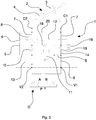
- the circuit element 11 could comprise, instead of or in addition to the aforesaid direct pressure relief valve, any one of the elements illustrated in figure 7 , i.e. a choke 111, a check valve 112 (with a spring, which is normally closed), a check valve 113 (with a spring, which is normally closed, with variable closing force), a piloted pressure relief valve 114 (with electric, for example, proportional, control), or another circuit element (also of known type) that is able to generate a loss of hydraulic load or a pressure difference ⁇ P, that is localized and variable with the variation of the flowrate.
- a choke 111 i.e. a choke 111, a check valve 112 (with a spring, which is normally closed), a check valve 113 (with a spring, which is normally closed, with variable closing force), a piloted pressure relief valve 114 (with electric, for example, proportional, control), or another circuit element (also of known type) that is able to generate a loss of hydraulic load
- the control device 1 may comprise, as in these embodiments, a first piloting conduit 12 arranged for piloting the second valve 8 with a first piloting pressure taken from a portion of circuit connected to a first side (supply side) of the circuit element 11. This first side of the circuit element 11 may be, in particular, facing the third port V1.
- the control device 1 may comprise, as in these embodiments, a second piloting conduit 13 arranged for piloting (opposing the first piloting pressure) the second valve 8 with a second piloting pressure taken from a portion of circuit connected to a second side (drain side) of the circuit element 11 opposite the aforesaid first side (supply side).
- the second piloting pressure may be taken from a portion of circuit connected to the circuit element 11 and to the third valve 10.
- the second piloting pressure may be taken, as in the embodiments of figures 1 , 3 , 4 and 6 , from a circuit portion connected to the fourth port V2 and to the first valve 6.
- the second piloting pressure may be taken, as in the embodiments of figures 2 and 5 , from a circuit portion connected to a port connected to a drain T.
- the circuit element 11 may be configured, in particular, so as to transform a flowrate variation, determined by the distributor D, into a variation of piloting pressure/s of the second valve 8 (in particular into a variation of the first piloting pressure and/or of the second piloting pressure and/or of the difference between the first and the second piloting pressure), as the variation of the flowrate will result in a consequent variation of the load loss (in particular of the pressure drop ⁇ P) through the circuit element 11.
- the circuit element 11 may be, thus, configured in such a manner as to generate a pressure difference (variable according to the flowrate in the circuit, in particular the flowrate generated by the distributor D) on the basis of which the (differential) dual piloting signal can be supplied to the second valve 8, i.e. to the control valve of the flowrate (balancing valve) during the load descent step.
- the aforesaid circuit for the passage of the operating fluid may comprise, as in these embodiments, at least one portion of conduit arranged for permitting a flow coming from the second conduit 7 and directed to a drain T, in a load descent step, so as to drain at least a second fraction of the operating fluid that cannot go to the first port C1 and cannot thus recirculate to the first chamber 3, as the first chamber 3 (stem side) is an actuator chamber with a cross section and a volume that are less than the second chamber 4 (bottom side).
- the aforesaid portion of conduit may comprise, as in the embodiments of figures 1 , 3 , 4 and 6 , a portion of conduit 14 that may connect the second conduit 7, in particular, to the third port V1.
- the portion of conduit 14 may connect the second conduit 7, in particular, to the third conduit 9.
- the circuit may comprise, as in the embodiments of figures 1 , 3 , 4 and 6 , a fourth valve 15 arranged in the portion of conduit 14.
- the fourth valve 15 may be arranged, in particular, to permit a flow that comes from the second conduit 7 and prevent a flow that is directed to the second conduit 7.
- the fourth valve 15 may comprise, in particular, a flow direction control valve, for example a check valve (with a spring, which is normally closed).
- the fourth valve 15 may be configured (for example by calibrating the spring) to open at a pressure value comprised, for example, between 0 and 10 bar, or between 0.1 and 5 bar, in particular around 1 bar.
- the calibration pressure of the fourth valve 15 may be, in particular, less than the calibration pressure of the third valve 10.
- the first conduit 5 may be connected, as in the embodiments of figures 1 , 3 , 4 and 6 , to a circuit portion (for example in a connection point) comprised between the circuit element 11 and the third valve 10.
- the control device is configured so as to pressurize the second chamber 4 (bottom side) directly by the supply pump (through the distributor D) in a load ascent step and so as not to pressurize (directly by the supply pump, through the distributor D) the first chamber 3 (stem side) either in an ascent step, or in a descent step.
- the control device 1 works, during the descent step, at relatively low piloting pressure (for example 25 bar).
- the calibration pressure of the second valve 8 may be, in particular, greater (slightly greater, for example than about 5 bar) than the calibration pressure of the circuit element 11 (pressure relief valve), so that, as in these embodiments, the second valve 8 may operate at about 25 bar and the circuit element 11 may operate at about 20 bar.
- the pressure in the first chamber 3 may remain (substantially) constant, in particular at a pressure value determined by the calibration of the third valve 10 (for example 5 bar). For this reason, the value of the pressure in the first chamber 3 may be in fact known, so it is possible to simplify the device, the use of the pressure-measuring means being avoidable that is normally provided, in devices of known type, to know the pressure in the first chamber 3 in order to ensure the safety of the lifting apparatus.
- the plurality of connecting ports may comprise, as in the embodiments of figures 2 and 5 , at least a fifth port 16 intended for connection to a drain T.
- the aforesaid portion of conduit may comprise, as in the embodiments of figures 2 and 5 , a portion of conduit 17 that branches off from a portion of the third conduit 9, in particular a portion of the third conduit 9 comprised between the circuit element 11 and the third valve 10, to connect the third conduit 9 to the fifth port 16 (drain).
- the control device is configured in such a manner as not to be affected by possible counterpressure generated by the distributor D, by virtue of the direct connection to the drain T through the fifth port 16.
- the aforesaid circuit for the passage of the operating fluid may comprise, as in the embodiment in figure 3 , a fifth valve 18 arranged in a circuit portion comprised between the second valve 8 and the first port C1.
- the fifth valve 18 may be arranged, in particular, to permit a flow that comes from the second valve 8 and/or to prevent a flow that is directed to the second valve 8 or to the third valve 10.
- the fifth valve 18 may comprise, in particular, a flow direction control valve, for example a check valve (with a spring, which is normally closed).
- the fifth valve 18 may be configured (for example by calibrating the spring) to open at a pressure value comprised, for example, between 0 and 10 bar, or between 0.1 and 5 bar, in particular around 1 bar (less than the calibration pressure of the third valve 10).
- the aforesaid circuit for the passage of the operating fluid may comprise, as in the embodiments of figures 3 and 6 , a sixth valve 19 arranged parallel to the fourth valve 15.
- the sixth valve 19 may be arranged in a circuit portion connected on one side to the first port C1 and on the opposite side to the third port V1.
- the embodiment in figure 3 enables not only the second chamber 4 (bottom side), but also the first chamber 3 (stem side) to be pressurized selectively.
- the embodiment in figure 6 enables not only the second chamber 4 (bottom side), but also the first chamber 3 (stem side) to be pressurized selectively.
- the sixth valve 19 may be arranged, in particular, to permit a (supply) flow that is directed to the first port C1, to pressurize the first chamber 3 (stem side) and prevent a flow that comes from the first port C1.
- the sixth valve 19 may comprise, in particular, a flow direction control valve, for example a check valve piloted to closure.
- the aforesaid circuit for the passage of the operating fluid may comprise, as in the embodiments of figures 3 and 6 , a third piloting conduit 20 for piloting the sixth valve 19 with a piloting pressure taken from a circuit portion connected to the first valve 6, to the second valve 8 and to the second port C2.
- the aforesaid circuit for the passage of the operating fluid may comprise, as in the embodiments of figures 3 and 6 , a choke S arranged on a circuit portion on the first side of the circuit element 11 (the side facing, in particular, the third port V1).
- the choke S may be arranged, in particular, between a removal point for taking the first piloting pressure (first piloting conduit 12) and a circuit zone connected to the third port V1, to the fourth valve 15 and to the sixth valve 19.
- the aforesaid circuit for the passage of the operating fluid may comprise, as in the embodiments of figures 4, 5 and 6 , a seventh valve 21 arranged in the second conduit 7 between the first port C1 and the third conduit 9.
- the seventh valve 21 may be arranged, in particular, to permit a direct flow to the first port C1 and to prevent a flow coming from the first port C1.
- the seventh valve 21 may comprise, in particular, a flow direction control valve, for example a check valve (with a spring, which is normally closed) piloted to opening.
- the seventh valve 21 may be configured (for example by calibrating the spring) for closing up to a pressure value comprised, for example, between 0 and 10 bar, or between 0.1 and 5 bar, in particular around 1 bar (less than the calibration pressure of the third valve 10).
- the aforesaid circuit for the passage of the operating fluid may comprise, as in the embodiments of figures 4, 5 and 6 , a fourth piloting conduit 22 for piloting to opening the seventh valve 21 with a piloting pressure taken in a circuit portion connected to the circuit element 11 and to the third valve 10.
- the control device permits operation of the dual effect actuator 2.
- the seventh valve 21 enables, in particular, the first chamber 3 (stem side) to be blocked and protected.
- the control device permits operation of the dual effect actuator 2.
- the seventh valve 21 permits, in particular, the first chamber 3 (stem side) to be blocked and protected.
- the fifth port 16 is connectable to the drain T.
- the control device is not affected, in this case, by possible counterpressure generated by the distributor D.
- the third valve 10 and/or the fourth valve 15 may act, in particular, as an insulating means arranged in a portion of circuit comprised between the circuit element 11 and the second conduit 7 (recirculating or regeneration conduit), so as to insulate the circuit element 11 from the first chamber 3 (stem side) of the actuator 2.
- the insulating means may comprise, as in these embodiments, a check valve that prevents a flow directed to the second conduit 7.
- the second conduit 7 may act as a recirculating or regeneration conduit to enable the operating fluid, in a load descent step, to exit from the second chamber 4 (bottom side) to partially re-enter the first chamber 3 (stem side).
- the third conduit 9 may act, at least partially, as a drain conduit that enables the fraction of fluid that cannot recirculate to be drained from the second conduit 7.
- the circuit element 11 may be used for generating a localized pressure difference that may be used to remove two piloting pressures that command in an opposite manner the second valve 8 that controls the flow into the second conduit 7 (recirculating flow) in particular in the descent step of the load.
Landscapes
- Engineering & Computer Science (AREA)
- Transportation (AREA)
- Structural Engineering (AREA)
- Chemical & Material Sciences (AREA)
- Combustion & Propulsion (AREA)
- Civil Engineering (AREA)
- Life Sciences & Earth Sciences (AREA)
- Geology (AREA)
- Mechanical Engineering (AREA)
- Fluid-Pressure Circuits (AREA)
Applications Claiming Priority (1)
| Application Number | Priority Date | Filing Date | Title |
|---|---|---|---|
| ITUA2016A002376A ITUA20162376A1 (it) | 2016-04-07 | 2016-04-07 | Dispositivo di controllo di un attuatore |
Publications (2)
| Publication Number | Publication Date |
|---|---|
| EP3228580A1 true EP3228580A1 (fr) | 2017-10-11 |
| EP3228580B1 EP3228580B1 (fr) | 2018-12-19 |
Family
ID=56555519
Family Applications (1)
| Application Number | Title | Priority Date | Filing Date |
|---|---|---|---|
| EP17164639.1A Active EP3228580B1 (fr) | 2016-04-07 | 2017-04-03 | Dispositif de commande d'un actionneur |
Country Status (2)
| Country | Link |
|---|---|
| EP (1) | EP3228580B1 (fr) |
| IT (1) | ITUA20162376A1 (fr) |
Cited By (4)
| Publication number | Priority date | Publication date | Assignee | Title |
|---|---|---|---|---|
| EP3599383A1 (fr) | 2018-07-27 | 2020-01-29 | Atlantic Fluid Tech S.r.l. | Dispositif de commande d'actionneur |
| IT201900016823A1 (it) | 2019-09-20 | 2021-03-20 | Atlantic Fluid Tech S R L | Dispositivo di Controllo di un Attuatore Idraulico |
| GB2636360A (en) * | 2023-12-07 | 2025-06-18 | Airbus Operations Ltd | Hydraulic actuator |
| GB2636362A (en) * | 2023-12-07 | 2025-06-18 | Airbus Operations Ltd | Hydraulic actuation system |
Citations (3)
| Publication number | Priority date | Publication date | Assignee | Title |
|---|---|---|---|---|
| EP1574474A2 (fr) * | 2004-03-13 | 2005-09-14 | Deere & Company | Agencement hydraulique |
| US7752842B2 (en) | 2005-08-19 | 2010-07-13 | Bucher Hydraulics Ag | Circuit for controlling a double-action hydraulic drive cylinder |
| EP2786958A1 (fr) | 2013-04-05 | 2014-10-08 | Bosch Rexroth Oil Control S.p.A. | Dispositif de commande pour la descente d'une charge |
-
2016
- 2016-04-07 IT ITUA2016A002376A patent/ITUA20162376A1/it unknown
-
2017
- 2017-04-03 EP EP17164639.1A patent/EP3228580B1/fr active Active
Patent Citations (3)
| Publication number | Priority date | Publication date | Assignee | Title |
|---|---|---|---|---|
| EP1574474A2 (fr) * | 2004-03-13 | 2005-09-14 | Deere & Company | Agencement hydraulique |
| US7752842B2 (en) | 2005-08-19 | 2010-07-13 | Bucher Hydraulics Ag | Circuit for controlling a double-action hydraulic drive cylinder |
| EP2786958A1 (fr) | 2013-04-05 | 2014-10-08 | Bosch Rexroth Oil Control S.p.A. | Dispositif de commande pour la descente d'une charge |
Cited By (4)
| Publication number | Priority date | Publication date | Assignee | Title |
|---|---|---|---|---|
| EP3599383A1 (fr) | 2018-07-27 | 2020-01-29 | Atlantic Fluid Tech S.r.l. | Dispositif de commande d'actionneur |
| IT201900016823A1 (it) | 2019-09-20 | 2021-03-20 | Atlantic Fluid Tech S R L | Dispositivo di Controllo di un Attuatore Idraulico |
| GB2636360A (en) * | 2023-12-07 | 2025-06-18 | Airbus Operations Ltd | Hydraulic actuator |
| GB2636362A (en) * | 2023-12-07 | 2025-06-18 | Airbus Operations Ltd | Hydraulic actuation system |
Also Published As
| Publication number | Publication date |
|---|---|
| EP3228580B1 (fr) | 2018-12-19 |
| ITUA20162376A1 (it) | 2017-10-07 |
Similar Documents
| Publication | Publication Date | Title |
|---|---|---|
| EP3078571B1 (fr) | Système de direction hydraulique | |
| EP3228580B1 (fr) | Dispositif de commande d'un actionneur | |
| US7243591B2 (en) | Hydraulic valve arrangement | |
| US7752842B2 (en) | Circuit for controlling a double-action hydraulic drive cylinder | |
| AU2007249080B2 (en) | Hydraulic valve arrangement | |
| US20170328380A1 (en) | Directional Control Valve | |
| JPH081202B2 (ja) | 単動式油圧シリンダの作動回路 | |
| US9797419B2 (en) | Hydraulic system with energy recovery | |
| US20170297617A1 (en) | Hydraulic steering | |
| US8910659B2 (en) | Hydraulic valve device | |
| KR20170101992A (ko) | 작업 기계의 압유 에너지 재생 장치 | |
| US20180044891A1 (en) | Control system for construction machinery | |
| EP3312436A1 (fr) | Dispositif de tube anti-rupture | |
| US20160258450A1 (en) | Control apparatus | |
| US10087957B2 (en) | Hydraulic system | |
| US20110030816A1 (en) | Control system for controlling a directional control valve | |
| EP2282064B1 (fr) | Système hydraulique à centre ouvert | |
| KR20180022768A (ko) | 유압 기계 유닛 및 유압 기계 유닛의 작동 방법 | |
| US8833391B2 (en) | Valve arrangement | |
| US6256986B1 (en) | Hydrostatic drive system | |
| GB2044366A (en) | Hydraulic Systems for Actuators | |
| US11286962B2 (en) | Flow control valve and hydraulic machine including the same | |
| CN111791949B (zh) | 液压转向布置 | |
| US20170037600A1 (en) | Drive control device for construction equipment and control method therefor | |
| US20120205563A1 (en) | Valve arrangement for actuating a load |
Legal Events
| Date | Code | Title | Description |
|---|---|---|---|
| PUAI | Public reference made under article 153(3) epc to a published international application that has entered the european phase |
Free format text: ORIGINAL CODE: 0009012 |
|
| STAA | Information on the status of an ep patent application or granted ep patent |
Free format text: STATUS: THE APPLICATION HAS BEEN PUBLISHED |
|
| AK | Designated contracting states |
Kind code of ref document: A1 Designated state(s): AL AT BE BG CH CY CZ DE DK EE ES FI FR GB GR HR HU IE IS IT LI LT LU LV MC MK MT NL NO PL PT RO RS SE SI SK SM TR |
|
| AX | Request for extension of the european patent |
Extension state: BA ME |
|
| STAA | Information on the status of an ep patent application or granted ep patent |
Free format text: STATUS: REQUEST FOR EXAMINATION WAS MADE |
|
| 17P | Request for examination filed |
Effective date: 20180330 |
|
| RBV | Designated contracting states (corrected) |
Designated state(s): AL AT BE BG CH CY CZ DE DK EE ES FI FR GB GR HR HU IE IS IT LI LT LU LV MC MK MT NL NO PL PT RO RS SE SI SK SM TR |
|
| GRAP | Despatch of communication of intention to grant a patent |
Free format text: ORIGINAL CODE: EPIDOSNIGR1 |
|
| STAA | Information on the status of an ep patent application or granted ep patent |
Free format text: STATUS: GRANT OF PATENT IS INTENDED |
|
| INTG | Intention to grant announced |
Effective date: 20180710 |
|
| GRAS | Grant fee paid |
Free format text: ORIGINAL CODE: EPIDOSNIGR3 |
|
| GRAA | (expected) grant |
Free format text: ORIGINAL CODE: 0009210 |
|
| STAA | Information on the status of an ep patent application or granted ep patent |
Free format text: STATUS: THE PATENT HAS BEEN GRANTED |
|
| AK | Designated contracting states |
Kind code of ref document: B1 Designated state(s): AL AT BE BG CH CY CZ DE DK EE ES FI FR GB GR HR HU IE IS IT LI LT LU LV MC MK MT NL NO PL PT RO RS SE SI SK SM TR |
|
| REG | Reference to a national code |
Ref country code: GB Ref legal event code: FG4D |
|
| RIN1 | Information on inventor provided before grant (corrected) |
Inventor name: ROSSI, CARLO ALBERTO Inventor name: STORCI, CHRISTIAN Inventor name: JACKSON, TREVOR |
|
| REG | Reference to a national code |
Ref country code: CH Ref legal event code: EP |
|
| REG | Reference to a national code |
Ref country code: IE Ref legal event code: FG4D |
|
| REG | Reference to a national code |
Ref country code: DE Ref legal event code: R096 Ref document number: 602017001427 Country of ref document: DE |
|
| REG | Reference to a national code |
Ref country code: AT Ref legal event code: REF Ref document number: 1078474 Country of ref document: AT Kind code of ref document: T Effective date: 20190115 |
|
| REG | Reference to a national code |
Ref country code: NL Ref legal event code: MP Effective date: 20181219 |
|
| PG25 | Lapsed in a contracting state [announced via postgrant information from national office to epo] |
Ref country code: NO Free format text: LAPSE BECAUSE OF FAILURE TO SUBMIT A TRANSLATION OF THE DESCRIPTION OR TO PAY THE FEE WITHIN THE PRESCRIBED TIME-LIMIT Effective date: 20190319 Ref country code: BG Free format text: LAPSE BECAUSE OF FAILURE TO SUBMIT A TRANSLATION OF THE DESCRIPTION OR TO PAY THE FEE WITHIN THE PRESCRIBED TIME-LIMIT Effective date: 20190319 Ref country code: LT Free format text: LAPSE BECAUSE OF FAILURE TO SUBMIT A TRANSLATION OF THE DESCRIPTION OR TO PAY THE FEE WITHIN THE PRESCRIBED TIME-LIMIT Effective date: 20181219 Ref country code: LV Free format text: LAPSE BECAUSE OF FAILURE TO SUBMIT A TRANSLATION OF THE DESCRIPTION OR TO PAY THE FEE WITHIN THE PRESCRIBED TIME-LIMIT Effective date: 20181219 Ref country code: HR Free format text: LAPSE BECAUSE OF FAILURE TO SUBMIT A TRANSLATION OF THE DESCRIPTION OR TO PAY THE FEE WITHIN THE PRESCRIBED TIME-LIMIT Effective date: 20181219 Ref country code: FI Free format text: LAPSE BECAUSE OF FAILURE TO SUBMIT A TRANSLATION OF THE DESCRIPTION OR TO PAY THE FEE WITHIN THE PRESCRIBED TIME-LIMIT Effective date: 20181219 |
|
| REG | Reference to a national code |
Ref country code: LT Ref legal event code: MG4D |
|
| REG | Reference to a national code |
Ref country code: AT Ref legal event code: MK05 Ref document number: 1078474 Country of ref document: AT Kind code of ref document: T Effective date: 20181219 |
|
| PG25 | Lapsed in a contracting state [announced via postgrant information from national office to epo] |
Ref country code: GR Free format text: LAPSE BECAUSE OF FAILURE TO SUBMIT A TRANSLATION OF THE DESCRIPTION OR TO PAY THE FEE WITHIN THE PRESCRIBED TIME-LIMIT Effective date: 20190320 Ref country code: SE Free format text: LAPSE BECAUSE OF FAILURE TO SUBMIT A TRANSLATION OF THE DESCRIPTION OR TO PAY THE FEE WITHIN THE PRESCRIBED TIME-LIMIT Effective date: 20181219 Ref country code: AL Free format text: LAPSE BECAUSE OF FAILURE TO SUBMIT A TRANSLATION OF THE DESCRIPTION OR TO PAY THE FEE WITHIN THE PRESCRIBED TIME-LIMIT Effective date: 20181219 Ref country code: RS Free format text: LAPSE BECAUSE OF FAILURE TO SUBMIT A TRANSLATION OF THE DESCRIPTION OR TO PAY THE FEE WITHIN THE PRESCRIBED TIME-LIMIT Effective date: 20181219 |
|
| PG25 | Lapsed in a contracting state [announced via postgrant information from national office to epo] |
Ref country code: NL Free format text: LAPSE BECAUSE OF FAILURE TO SUBMIT A TRANSLATION OF THE DESCRIPTION OR TO PAY THE FEE WITHIN THE PRESCRIBED TIME-LIMIT Effective date: 20181219 |
|
| PG25 | Lapsed in a contracting state [announced via postgrant information from national office to epo] |
Ref country code: PL Free format text: LAPSE BECAUSE OF FAILURE TO SUBMIT A TRANSLATION OF THE DESCRIPTION OR TO PAY THE FEE WITHIN THE PRESCRIBED TIME-LIMIT Effective date: 20181219 Ref country code: PT Free format text: LAPSE BECAUSE OF FAILURE TO SUBMIT A TRANSLATION OF THE DESCRIPTION OR TO PAY THE FEE WITHIN THE PRESCRIBED TIME-LIMIT Effective date: 20190419 Ref country code: ES Free format text: LAPSE BECAUSE OF FAILURE TO SUBMIT A TRANSLATION OF THE DESCRIPTION OR TO PAY THE FEE WITHIN THE PRESCRIBED TIME-LIMIT Effective date: 20181219 Ref country code: CZ Free format text: LAPSE BECAUSE OF FAILURE TO SUBMIT A TRANSLATION OF THE DESCRIPTION OR TO PAY THE FEE WITHIN THE PRESCRIBED TIME-LIMIT Effective date: 20181219 |
|
| PG25 | Lapsed in a contracting state [announced via postgrant information from national office to epo] |
Ref country code: EE Free format text: LAPSE BECAUSE OF FAILURE TO SUBMIT A TRANSLATION OF THE DESCRIPTION OR TO PAY THE FEE WITHIN THE PRESCRIBED TIME-LIMIT Effective date: 20181219 Ref country code: IS Free format text: LAPSE BECAUSE OF FAILURE TO SUBMIT A TRANSLATION OF THE DESCRIPTION OR TO PAY THE FEE WITHIN THE PRESCRIBED TIME-LIMIT Effective date: 20190419 Ref country code: RO Free format text: LAPSE BECAUSE OF FAILURE TO SUBMIT A TRANSLATION OF THE DESCRIPTION OR TO PAY THE FEE WITHIN THE PRESCRIBED TIME-LIMIT Effective date: 20181219 Ref country code: SK Free format text: LAPSE BECAUSE OF FAILURE TO SUBMIT A TRANSLATION OF THE DESCRIPTION OR TO PAY THE FEE WITHIN THE PRESCRIBED TIME-LIMIT Effective date: 20181219 Ref country code: SM Free format text: LAPSE BECAUSE OF FAILURE TO SUBMIT A TRANSLATION OF THE DESCRIPTION OR TO PAY THE FEE WITHIN THE PRESCRIBED TIME-LIMIT Effective date: 20181219 |
|
| REG | Reference to a national code |
Ref country code: DE Ref legal event code: R097 Ref document number: 602017001427 Country of ref document: DE |
|
| PLBE | No opposition filed within time limit |
Free format text: ORIGINAL CODE: 0009261 |
|
| STAA | Information on the status of an ep patent application or granted ep patent |
Free format text: STATUS: NO OPPOSITION FILED WITHIN TIME LIMIT |
|
| PG25 | Lapsed in a contracting state [announced via postgrant information from national office to epo] |
Ref country code: DK Free format text: LAPSE BECAUSE OF FAILURE TO SUBMIT A TRANSLATION OF THE DESCRIPTION OR TO PAY THE FEE WITHIN THE PRESCRIBED TIME-LIMIT Effective date: 20181219 Ref country code: AT Free format text: LAPSE BECAUSE OF FAILURE TO SUBMIT A TRANSLATION OF THE DESCRIPTION OR TO PAY THE FEE WITHIN THE PRESCRIBED TIME-LIMIT Effective date: 20181219 |
|
| 26N | No opposition filed |
Effective date: 20190920 |
|
| REG | Reference to a national code |
Ref country code: BE Ref legal event code: MM Effective date: 20190430 |
|
| PG25 | Lapsed in a contracting state [announced via postgrant information from national office to epo] |
Ref country code: LU Free format text: LAPSE BECAUSE OF NON-PAYMENT OF DUE FEES Effective date: 20190403 Ref country code: MC Free format text: LAPSE BECAUSE OF FAILURE TO SUBMIT A TRANSLATION OF THE DESCRIPTION OR TO PAY THE FEE WITHIN THE PRESCRIBED TIME-LIMIT Effective date: 20181219 |
|
| PG25 | Lapsed in a contracting state [announced via postgrant information from national office to epo] |
Ref country code: BE Free format text: LAPSE BECAUSE OF NON-PAYMENT OF DUE FEES Effective date: 20190430 Ref country code: FR Free format text: LAPSE BECAUSE OF NON-PAYMENT OF DUE FEES Effective date: 20190430 Ref country code: SI Free format text: LAPSE BECAUSE OF FAILURE TO SUBMIT A TRANSLATION OF THE DESCRIPTION OR TO PAY THE FEE WITHIN THE PRESCRIBED TIME-LIMIT Effective date: 20181219 |
|
| PG25 | Lapsed in a contracting state [announced via postgrant information from national office to epo] |
Ref country code: TR Free format text: LAPSE BECAUSE OF FAILURE TO SUBMIT A TRANSLATION OF THE DESCRIPTION OR TO PAY THE FEE WITHIN THE PRESCRIBED TIME-LIMIT Effective date: 20181219 |
|
| PG25 | Lapsed in a contracting state [announced via postgrant information from national office to epo] |
Ref country code: IE Free format text: LAPSE BECAUSE OF NON-PAYMENT OF DUE FEES Effective date: 20190403 |
|
| REG | Reference to a national code |
Ref country code: CH Ref legal event code: PL |
|
| PG25 | Lapsed in a contracting state [announced via postgrant information from national office to epo] |
Ref country code: CH Free format text: LAPSE BECAUSE OF NON-PAYMENT OF DUE FEES Effective date: 20200430 Ref country code: LI Free format text: LAPSE BECAUSE OF NON-PAYMENT OF DUE FEES Effective date: 20200430 |
|
| PG25 | Lapsed in a contracting state [announced via postgrant information from national office to epo] |
Ref country code: CY Free format text: LAPSE BECAUSE OF FAILURE TO SUBMIT A TRANSLATION OF THE DESCRIPTION OR TO PAY THE FEE WITHIN THE PRESCRIBED TIME-LIMIT Effective date: 20181219 |
|
| PG25 | Lapsed in a contracting state [announced via postgrant information from national office to epo] |
Ref country code: MT Free format text: LAPSE BECAUSE OF FAILURE TO SUBMIT A TRANSLATION OF THE DESCRIPTION OR TO PAY THE FEE WITHIN THE PRESCRIBED TIME-LIMIT Effective date: 20181219 Ref country code: HU Free format text: LAPSE BECAUSE OF FAILURE TO SUBMIT A TRANSLATION OF THE DESCRIPTION OR TO PAY THE FEE WITHIN THE PRESCRIBED TIME-LIMIT; INVALID AB INITIO Effective date: 20170403 |
|
| GBPC | Gb: european patent ceased through non-payment of renewal fee |
Effective date: 20210403 |
|
| PG25 | Lapsed in a contracting state [announced via postgrant information from national office to epo] |
Ref country code: GB Free format text: LAPSE BECAUSE OF NON-PAYMENT OF DUE FEES Effective date: 20210403 |
|
| PG25 | Lapsed in a contracting state [announced via postgrant information from national office to epo] |
Ref country code: MK Free format text: LAPSE BECAUSE OF FAILURE TO SUBMIT A TRANSLATION OF THE DESCRIPTION OR TO PAY THE FEE WITHIN THE PRESCRIBED TIME-LIMIT Effective date: 20181219 |
|
| P01 | Opt-out of the competence of the unified patent court (upc) registered |
Effective date: 20230529 |
|
| PGFP | Annual fee paid to national office [announced via postgrant information from national office to epo] |
Ref country code: DE Payment date: 20250429 Year of fee payment: 9 |
|
| PGFP | Annual fee paid to national office [announced via postgrant information from national office to epo] |
Ref country code: IT Payment date: 20250429 Year of fee payment: 9 |