EP3228794B1 - Profil für rahmen von türen, wandelementen oder fenstern - Google Patents
Profil für rahmen von türen, wandelementen oder fenstern Download PDFInfo
- Publication number
- EP3228794B1 EP3228794B1 EP16163879.6A EP16163879A EP3228794B1 EP 3228794 B1 EP3228794 B1 EP 3228794B1 EP 16163879 A EP16163879 A EP 16163879A EP 3228794 B1 EP3228794 B1 EP 3228794B1
- Authority
- EP
- European Patent Office
- Prior art keywords
- profile
- reflector plate
- reflector
- profile according
- webs
- Prior art date
- Legal status (The legal status is an assumption and is not a legal conclusion. Google has not performed a legal analysis and makes no representation as to the accuracy of the status listed.)
- Active
Links
Images


Classifications
-
- E—FIXED CONSTRUCTIONS
- E06—DOORS, WINDOWS, SHUTTERS, OR ROLLER BLINDS IN GENERAL; LADDERS
- E06B—FIXED OR MOVABLE CLOSURES FOR OPENINGS IN BUILDINGS, VEHICLES, FENCES OR LIKE ENCLOSURES IN GENERAL, e.g. DOORS, WINDOWS, BLINDS, GATES
- E06B3/00—Window sashes, door leaves, or like elements for closing wall or like openings; Layout of fixed or moving closures, e.g. windows in wall or like openings; Features of rigidly-mounted outer frames relating to the mounting of wing frames
- E06B3/04—Wing frames not characterised by the manner of movement
- E06B3/263—Frames with special provision for insulation
- E06B3/26301—Frames with special provision for insulation with prefabricated insulating strips between two metal section members
- E06B3/26303—Frames with special provision for insulation with prefabricated insulating strips between two metal section members with thin strips, e.g. defining a hollow space between the metal section members
Definitions
- the invention relates to a profile for frames of doors, wall elements or windows.
- Known profiles include an upper part and a lower part, which are usually designed as a cavity profile.
- upper part and lower part are usually connected to each other by means of insulating webs made of a plastic. It is also known to improve the insulating properties of the composite profile to equip the insulating bars with transverse surfaces, which reduce heat losses through convection and heat radiation, such as in the DE 295 20 444 U1 or EP 2 256 280 A2 shown.
- From the EP 1 510 643 A1 is a profile for frames of wall elements, doors or windows with a top and a base known.
- Upper part and lower part are connected via side walls with each other, wherein the side walls are inclined de webs, which reduce heat conduction.
- the inventive profile comprises an upper part and a lower part, each with an outer wall.
- Upper part and lower part can but also be designed differently.
- Upper part and / or lower part may be formed, for example, as a cavity profile.
- the upper part and / or lower part can consist of a solid profile.
- the metal for the upper part and / or lower part and / or profile part for example, steel, stainless steel, aluminum, Cortenstahl, brass and copper come into question. Metals and / or alloys with good corrosion resistance and good thermal insulation properties may be preferred.
- openings for attaching locks, switches and the like. And / or for the implementation of cables and cables may be formed.
- And / or implementation of cables and cables is also possible in the space formed between the upper part and lower part.
- Upper part and lower part are connected to each other by webs of metal.
- the webs may be designed such that a distance from the upper part or lower part is possible at any time.
- upper part and lower part are equally spaced over the entire length of the profile.
- At least one reflector plate is arranged between upper part and lower part.
- the at least one reflector plate preferably extends substantially over the entire width of the profile. Preferably, the at least one reflector plate also extends over the entire length of the profile.
- the effect of the reflector plate can already be achieved by the surface of the webs, which are formed parallel to the upper part or lower part.
- the webs preferably additionally comprise sections which run parallel to the upper part and / or lower part and serve as a reflector surface.
- the longitudinal axis of the upper or lower part corresponds to a longitudinal direction of the upper or lower part, which is usually also referred to as length and represents the largest dimension of the upper and lower parts.
- the width of the profile extends according to the invention perpendicular to the length in the plane of the outer wall.
- the reflector plate to extend substantially over the entire width of the profile and the connection between the upper part and lower part via webs and not to have a continuous wall.
- the webs are for weight and réelleleitrank (reduction of the lambda value) to be preferred.
- the webs with respect to the longitudinal axis of the upper part and lower part, respectively in a first and second side region of the upper or lower part.
- the at least one reflector plate extends from the webs of the first side region to the webs of the second side region. It has been shown that it is not necessary for a good thermal insulation, that the side portions of the profile are completely closed. It is sufficient that the reflector plate extends substantially over the entire width of the profile. Thus, only webs can be arranged in the side regions, which for weight and jacketleitschreibn to prefer are.
- the reflector plate also stiffens the profile, so that the webs can be made correspondingly narrow and lightweight.
- a bullet-resistant effect can also be achieved.
- additional materials may be used.
- additional armor made of a metal and / or synthetic fibers (e.g., aramid) may be placed in the top and / or bottom and / or in the space formed between top and bottom.
- Upper part and / or lower part can also or alternatively be manufactured as a solid profile.
- the webs of the respective side region are preferably strung together, so that in each case in the first and second side region, the webs are arranged in alignment in the longitudinal direction.
- the profile may have juxtaposed webs which connect the upper part and lower part with each other.
- the profile may have juxtaposed webs which connect the upper part and lower part with each other.
- only a single row of webs is present, which is preferably arranged centrally of the upper part and / or lower part.
- Such a design is particularly advantageous for very narrow in width profiles formed.
- the at least one reflector plate preferably has one or two substantially flat reflector surfaces.
- a substantially flat reflector surface is simple in production and also best suited for the reflective properties of the reflector surface.
- the profile comprises a plurality of reflector plates with reflector surfaces arranged parallel to one another.
- the multiple arrangement of reflector plates, the insulating properties and fire resistance can be improved.
- At least one reflector surface is preferably provided with an infrared-radiation-reflective coating.
- the inner surfaces of the upper part and / or lower part facing the reflector surface (s) are also provided with such a coating.
- the at least one reflector surface is arranged in particular parallel to the outer wall of the upper part and lower part. More preferably, both upper part and lower part are formed such that one of the reflector plate facing inner wall is also arranged parallel to the reflector surface.
- the reflector plate is preferably made of metal.
- reflector plates with a polished surface are particularly preferred because they positively affect the return properties of the reflector plate.
- the webs are arranged obliquely to form a truss arrangement.
- obliquely means an angle of 1 ° to 89 ° to the longitudinal axis, or 91 ° to 179 °.
- a framework arrangement is particularly preferred for the shear strength of the profile.
- the webs can be cut or punched from a single metal sheet to form a zigzag profile.
- the webs can also be arranged perpendicular to the outer wall of the upper part and / or lower part.
- the at least one reflector plate openings in which the webs are inserted.
- This embodiment provides a simple way of attaching the reflector plate.
- the reflector plate can be easily attached to the webs.
- the reflector plate may be provided with further means, which serve for attachment to the webs. It is conceivable a connector with locking elements on the web or on the reflector plate, which engage in corresponding openings of the reflector plate or the web.
- a clamping connection by folding is also conceivable as a screw or rivet connection, a welded connection and / or an adhesive bond.
- Another embodiment of the invention provides that the webs are formed of at least two segments and at least a reflector plate is formed as a connecting piece for the two segments.
- the webs are provided in an end region with fastening means for attachment to the upper part or lower part.
- the fastening means may be formed as a latching element, which are inserted into corresponding openings or grooves of the upper or lower part.
- the webs can be provided with openings which cooperate with the insertion into the upper or lower part of me locking means.
- the connection can be made by clamping, folding or rolling sections of the web with the upper or lower part. Further possibilities are a screw and / or rivet connection and / or a welded connection and / or an adhesive connection.
- the at least one reflector plate is integrally formed with the webs and / or web segments.
- the webs and / or web segments and the at least one reflector plate are punched or cut out of a single sheet metal part and are then folded to form the three-dimensional structure.
- the profile may further comprise an intumescent material and / or a water-releasing material (eg, water glass) and / or a heat-insulating material disposed between the top and the bottom and / or only in the top or bottom is.
- the intumescent material and / or the fire-releasing material (eg water glass) and / or the heat-insulating Material may for example be arranged only between the upper part and the reflector plate or only between two reflector plates.
- the at least one reflector plate is provided with means for fixing a cover.
- the means for fixing a cover are preferably formed as a latching element.
- Other options such as clamping, screw, rivet and adhesive joints are also conceivable.
- the profile and in particular the reflector plates and / or the webs preferably have means for attachment, for example on a wall or for the attachment of locks and the like., On. These means are preferably designed as an opening for a screw or bolt / pin.
- the Indian FIG. 1 shown section of a profile consists of an upper part 1 and a lower part 2, which are formed as a hollow profile made of metal. Each of the other part facing away from surface 3 and 4 is referred to as the outer wall.
- a longitudinal axis L is indicated by the dashed-dotted line.
- the upper part 1 and the lower part 1 are connected by obliquely and truss-like webs 5 made of metal. Between upper part 1 and lower part 2, parallel to the outer walls 3 and 4 reflector plates 8 and 8 'are arranged of a metal, which extend over the entire length and width of the profile.
- Each of the adjacent upper part 1 and lower part 2 facing surface is referred to as a reflector surface 9 or 9 'and is flat and polished.
- the remaining, the other reflector plate facing surface is referred to as a reflector surface 99 and 99 'and is also flat and polished.
- the webs 5 are each arranged in a side region 6 and 7 of the upper part 1 and lower part 2.
- the reflector plate 8 or 8 ' has curved side parts 11, which serve as fastening means for a side cover, not shown here.
- FIGS. 2a and 2b show possible variants of a shell 1 on.
- the in the FIGS. 2a and 2b Variants shown are also applicable to the lower part 2 accordingly.
- the upper part 1 of FIG. 2a is designed as a hollow profile. On the wall facing away from the outer wall openings 12 are provided for fixing the webs 5.
- the upper part 1 of FIG. 2b is formed as a composite profile and consists of a sub-profile 13 of metal and a slip-14.
- the attachment profile 14 may be made of an example optically appealing material such as stone, plastic or wood.
- the sub-profile 13 also has locking lugs 15, which serve for fastening of the attachment profile 14.
- In Aufsteckprofil 14 recesses 16 are also provided, which coincide with plug-on profile 14 with the openings 12 of the sub-profile 13 and serve to fasten the webs 5.
- the attachment of the webs 5 is in the FIG. 3 shown.
- an end region 53 of a web 5 can be provided with a latching nose 55, which engages behind it after being inserted into the opening 12 of the upper part 1.
- the compound can also according to FIG. 3b take place by folding or curling an end portion 53 of the web 5 with a correspondingly formed receiving portion of the upper part 1.
- an end portion 53 of the web 5 is welded to the upper part 1.
- FIGS. 4 to 8 Various possibilities of attachment of the reflector plate 8 with the web 5 are shown.
- the in the FIG. 4a shown connector which in detail in the FIG. 4b is visible, is realized by the fact that the reflector plate 8 has an opening 17.
- the web 5 has a portion 18 which is bent and arranged parallel to the reflector plate 8.
- FIGS. 5 to 8 are alternatives to the plug connection of FIG. 4 shown.
- FIGS. 5a and 5b In the FIGS. 5a and 5b is visible that an end portion 53 'of the web 5 is folded with an edge portion 20 of the reflector plate 8 to produce a clamping connection.
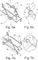
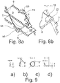
- FIG. 6a and 6b a screw connection is shown.
- the reflector plate 8 is by means of a screw 21 with a bent portion 18 (analogous to FIG. 4 ) of the web 5 connected.
- the screw 21 can also find a rivet application.
- FIGS. 7a shown to us 7b Another alternative is in the FIGS. 7a shown to us 7b. There, an edge of the reflector plate 8 is brought into contact with an edge of the web 5 and welded.
- FIGS. 8a and 8b an adhesive bond shown. Analogous to FIG. 4 a portion 18 of the web 5 is bent, so that the portion 18 extends parallel to the reflector plate 8. Between section 18 and reflector plate 8, an adhesive layer 22 is then attached.
- FIGS. 9a to 9d For example, different cross sections of the webs 5 are shown.
- FIG. 9a can the webs 5, depending on the static requirements, also a curved section ( FIG. 9b ), a round cross-section ( Figure 9c), which may also be formed of a solid metal rod, or an L-shaped cross section ( FIG. 9d ) respectively.
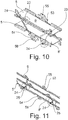
- FIG. 10 In the FIG. 10 is shown a possible wall mounting. In the region of the curved side parts 11, projections 23 are formed with an opening 24, which are used for fastening the profile.
- FIG. 11 an alternative is shown, which additionally allows the attachment of locking mechanisms.
- the openings 24 are formed in connecting portions 25 which connect the reflector plate 8 and the reflector plate 8 '.
- the connecting sections 25 can be formed integrally with the reflector plates 8 and 8 'or as a separate component, which is subsequently connected to the reflector plates 8 and 8'.
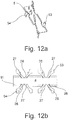
- FIG. 12a a possibility of forming a reflector plate 8 with webs 5 is shown.
- the reflector plate 8 and the webs 5 are cut out of a layer of metal and then folded.
- the side parts 11 are bent along the folding line 26 with respect to the sheet plane up or down by 90 °.
- the webs 5 are also bent either along the fold line 27 up or the fold line 28 down.
- the end portions 53 and 54 of the webs 5 are in the FIG. 12 shown purely schematically, but include mounting options for the upper and lower part, preferably in the FIG. 3 shown mounting options.
- FIG. 13a a construction with two reflector plates 8 and 8 'is shown, which is formed from a single folded sheet metal part.
- the cutout pattern is in the FIG. 13b visible.
- the sections 18 are visible, which are provided with an opening 21 '.
- the openings 21 ' come into conformity with the openings 21 "of the reflector plate 8, so that a corresponding screw connection, as in FIG. 6 , can come about.
- the sections 18 may also be configured differently, so that one of the in the FIGS. 4 to 8 shown mounting options is also conceivable.
- FIGS. 13c to 13h are the bending steps for producing a reflector assembly according to FIG. 13a shown. In the the FIGS. 13c to 13h However, the order of steps shown is not binding.
- the cover fasteners 11 are also bent by 90 ° on the same side of the sheet plane as the end portions 53 and 54.
- the plane of the reflector plate 8 is bent by 90 ° with respect to the plane of the reflector plate 8 '.
- the reflector plate 8 ' is also bent by 90 °, so that the reflector plate 8 and 8' are now parallel to each other and the end portions 53 and 54 are arranged facing away from each other.
- the section 18 is then folded by 90 °, as in the Figure 13g shown.
- FIG. 14 an exploded view of another embodiment of the inventive profile is shown.
- Upper part 1 and lower part 2 have openings 12, which are formed for insertion of the webs 5.
- the webs 5 are formed as a stamped part and have sections 51, which are provided with openings 52.
- the sections 51 extend parallel to the upper part 1 or lower part 2.
- the reflector plates 8 and 8 ' have at the side edges projections 81, which in terms of dimensions and spacing are matched to the openings 52 so that the projections 81 are inserted into the openings 52 for positioning and fixing the reflector plates 8 and 8 '.
- An attachment of the projections 81 is also conceivable.
- the end portions 53 and 54 of the webs 5 are preferably according to FIG. 3 connected to the upper part 1 and lower part 2.
- FIG. 15 a further embodiment of the inventive profile is shown.
- the upper part 1 and the lower part 2 are also provided with openings 12 which serve for fastening the webs 5.
- the profile is formed from a sandwich arrangement.
- the reflector plate 8 or 8 ' is formed by joining both plates 82 and 83 or 84 and 85.
- the plates 82 and 83 or 84 and 85 are preferably glued or welded.
- the end portions 53 and 54 of the webs 5 are preferably according to FIG. 3 connected to the upper part 1 and lower part 2.
- FIG. 16 a further variant of the inventive profile is shown.
- the upper part 1 and the lower part 2 are also provided with openings 12 which serve for fastening the webs 5.
- the reflector plates 8 and 8 ' have openings 10, which are formed for the passage of the webs 5.
- the webs 5 are cut / punched out of a single sheet metal part and run with a zigzag pattern.
- the attachment of the webs 5 with the upper part 1 and the lower part 2 takes place as above with respect to the FIG. 3 mentioned. In this case, the attachment takes place by means of locking lugs 55 and 56th
- the inventive profile may also include a single row of webs 5, as in the FIGS. 17 and 18 shown. These embodiments are particularly preferred when the profile must be made very narrow. Depending on the embodiment, a width of 6 mm is possible, which allows a very filigree design of components.
- FIG. 17a Visible is the profile shown there formed in several parts.
- Upper part 1 and lower part 2 are connected by webs 5, which are formed like a truss.
- Upper part 1 and lower part 2 are preferably welded to the central part, which has the webs 5.
- the reflector plates 8, 8 'and 8 are integrally formed with the webs 5 and extend parallel to the upper part 1 and the lower part 2. As shown in FIG. 17b Visible protrude the reflector plates 8, 8 'and 8 "side of the webs 5 out.
- FIG. 18 is also a profile according to the invention shown with a single row of webs, which, however, is formed from a single sheet metal part.
- visible upper part 1 and lower part 2 are formed from a folded sheet metal.
- the webs 5 are formed by cutting / punching.
- the reflector surfaces 8 and 8 ' are formed by the portions 51, which extend parallel to the upper part 1 and lower part 2 and the webs 5 intersect.
Landscapes
- Engineering & Computer Science (AREA)
- Civil Engineering (AREA)
- Structural Engineering (AREA)
- Roof Covering Using Slabs Or Stiff Sheets (AREA)
Priority Applications (2)
| Application Number | Priority Date | Filing Date | Title |
|---|---|---|---|
| PL16163879T PL3228794T3 (pl) | 2016-04-05 | 2016-04-05 | Profil do ram drzwi, elementów ściennych lub okien |
| EP16163879.6A EP3228794B1 (de) | 2016-04-05 | 2016-04-05 | Profil für rahmen von türen, wandelementen oder fenstern |
Applications Claiming Priority (1)
| Application Number | Priority Date | Filing Date | Title |
|---|---|---|---|
| EP16163879.6A EP3228794B1 (de) | 2016-04-05 | 2016-04-05 | Profil für rahmen von türen, wandelementen oder fenstern |
Publications (2)
| Publication Number | Publication Date |
|---|---|
| EP3228794A1 EP3228794A1 (de) | 2017-10-11 |
| EP3228794B1 true EP3228794B1 (de) | 2019-05-08 |
Family
ID=55661335
Family Applications (1)
| Application Number | Title | Priority Date | Filing Date |
|---|---|---|---|
| EP16163879.6A Active EP3228794B1 (de) | 2016-04-05 | 2016-04-05 | Profil für rahmen von türen, wandelementen oder fenstern |
Country Status (2)
| Country | Link |
|---|---|
| EP (1) | EP3228794B1 (pl) |
| PL (1) | PL3228794T3 (pl) |
Family Cites Families (4)
| Publication number | Priority date | Publication date | Assignee | Title |
|---|---|---|---|---|
| DE4443762A1 (de) * | 1994-12-08 | 1996-06-13 | Schueco Int Kg | Rahmenwerk aus Metallprofilen in Brandschutzausführung für Fenster, Türen, Fassaden oder Glasdächer |
| DE29520444U1 (de) | 1995-12-22 | 1996-03-21 | Lange, Rolf-Peter, 90453 Nürnberg | Dämmstege zur Verbesserung der Wärmedämmung |
| PL1510643T3 (pl) * | 2003-09-01 | 2018-06-29 | Forster Profilsysteme Ag | Profil i sposób wytwarzania profilu |
| DE202007016649U1 (de) | 2007-04-02 | 2008-04-30 | Technoform Caprano Und Brunnhofer Gmbh & Co. Kg | Leiterförmiger Isoliersteg für ein Verbundprofil für Fenster-, Türen- und Fassadenelemente und Verbundprofil für Fenster-, Türen- und Fassadenelemente |
-
2016
- 2016-04-05 PL PL16163879T patent/PL3228794T3/pl unknown
- 2016-04-05 EP EP16163879.6A patent/EP3228794B1/de active Active
Non-Patent Citations (1)
| Title |
|---|
| None * |
Also Published As
| Publication number | Publication date |
|---|---|
| EP3228794A1 (de) | 2017-10-11 |
| PL3228794T3 (pl) | 2019-10-31 |
Similar Documents
| Publication | Publication Date | Title |
|---|---|---|
| EP2476853B1 (de) | Verbundprofil für Fenster, Türen und Fassaden sowie Verfahren zu dessen Herstellung | |
| EP1980701B1 (de) | Wärmegedämmtes Verbundprofil, insbesondere für Fenster, Türen, Fassaden und dergleichen | |
| EP0100824B1 (de) | Verbundprofil, insbesondere für Rahmen von Fenstern, Türen und Fassadenelementen | |
| DE102011056090B4 (de) | Türblatt, insbesondere feuerschutz-türblatt | |
| EP1988229B1 (de) | Paneel zum Bau einer Wand oder einer Decke eines Bauwerks und Bauwerksteil hergestellt aus solchen Paneelen | |
| EP2003280B1 (de) | Türblatt, vorzugsweise für eine Hauseingangstür. | |
| DE102008034055B4 (de) | Sicherheitsraum | |
| DE102011117170B4 (de) | Wärmegedämmtes Profil | |
| DE29614086U1 (de) | Steckverbindung für Wand- oder Dachelemente aus stranggepreßtem Kunststoff | |
| EP1840314B1 (de) | Bauelement in Brandschutzausführung | |
| DE102004038868A1 (de) | Wärmegedämmtes Profil für Fenster, Türen, Fassadenelemente und dergleichen | |
| EP3228794B1 (de) | Profil für rahmen von türen, wandelementen oder fenstern | |
| EP1944451B1 (de) | Zarge für Feuerschutztüren, welche aus mehreren parallel verlaufenden Teilprofilen gebildet wird | |
| EP3854982A1 (de) | Türflügel sowie tür mit einem blendrahmen und einem türflügel | |
| EP2781866B2 (de) | Wandplatte für eine Trockenanlage und Verfahren zum Herstellen der Wandplatte | |
| EP2105063A1 (de) | Möbelkorpus | |
| EP2157270B1 (de) | Wärmedämmprofil für Brandschutzkonstruktionen sowie Verbundprofil für Fassaden, Fenster und Türen | |
| EP1182317B1 (de) | Wärmedämmprofil für Brandschutzkonstruktionen | |
| AT402836B (de) | Halteeinrichtung für platten, insbesondere glasplatten, in ausschnitten von bauteilen | |
| EP1771297B1 (de) | Schalen-/plattenförmiges bauelement, bestehent aus einer ersten schicht, einer zwischenschicht sowie einer zweiten schicht | |
| DE202010013228U1 (de) | Auflageanordnung für ein Fenster, eine Tür o.dgl. | |
| EP3450649B1 (de) | Befestigungsprofil | |
| EP1728934B1 (de) | Profil für Rahmen von Fenstern, Wandelementen oder Türen | |
| DE4227531C2 (de) | Eckverbinder für ein Rahmengestell eines Schaltschrankes | |
| DE10203276C2 (de) | Leichtbaustrukturelement mit arretierendem Nut- und Federeffekt |
Legal Events
| Date | Code | Title | Description |
|---|---|---|---|
| PUAI | Public reference made under article 153(3) epc to a published international application that has entered the european phase |
Free format text: ORIGINAL CODE: 0009012 |
|
| STAA | Information on the status of an ep patent application or granted ep patent |
Free format text: STATUS: THE APPLICATION HAS BEEN PUBLISHED |
|
| AK | Designated contracting states |
Kind code of ref document: A1 Designated state(s): AL AT BE BG CH CY CZ DE DK EE ES FI FR GB GR HR HU IE IS IT LI LT LU LV MC MK MT NL NO PL PT RO RS SE SI SK SM TR |
|
| AX | Request for extension of the european patent |
Extension state: BA ME |
|
| STAA | Information on the status of an ep patent application or granted ep patent |
Free format text: STATUS: REQUEST FOR EXAMINATION WAS MADE |
|
| 17P | Request for examination filed |
Effective date: 20180314 |
|
| RBV | Designated contracting states (corrected) |
Designated state(s): AL AT BE BG CH CY CZ DE DK EE ES FI FR GB GR HR HU IE IS IT LI LT LU LV MC MK MT NL NO PL PT RO RS SE SI SK SM TR |
|
| GRAP | Despatch of communication of intention to grant a patent |
Free format text: ORIGINAL CODE: EPIDOSNIGR1 |
|
| STAA | Information on the status of an ep patent application or granted ep patent |
Free format text: STATUS: GRANT OF PATENT IS INTENDED |
|
| INTG | Intention to grant announced |
Effective date: 20181123 |
|
| GRAS | Grant fee paid |
Free format text: ORIGINAL CODE: EPIDOSNIGR3 |
|
| GRAA | (expected) grant |
Free format text: ORIGINAL CODE: 0009210 |
|
| STAA | Information on the status of an ep patent application or granted ep patent |
Free format text: STATUS: THE PATENT HAS BEEN GRANTED |
|
| AK | Designated contracting states |
Kind code of ref document: B1 Designated state(s): AL AT BE BG CH CY CZ DE DK EE ES FI FR GB GR HR HU IE IS IT LI LT LU LV MC MK MT NL NO PL PT RO RS SE SI SK SM TR |
|
| REG | Reference to a national code |
Ref country code: GB Ref legal event code: FG4D Free format text: NOT ENGLISH |
|
| REG | Reference to a national code |
Ref country code: CH Ref legal event code: EP Ref country code: AT Ref legal event code: REF Ref document number: 1130380 Country of ref document: AT Kind code of ref document: T Effective date: 20190515 |
|
| REG | Reference to a national code |
Ref country code: DE Ref legal event code: R096 Ref document number: 502016004515 Country of ref document: DE Ref country code: IE Ref legal event code: FG4D Free format text: LANGUAGE OF EP DOCUMENT: GERMAN |
|
| REG | Reference to a national code |
Ref country code: CH Ref legal event code: NV Representative=s name: ORITI PATENTS - FRANCO ORITI, CH |
|
| REG | Reference to a national code |
Ref country code: NL Ref legal event code: FP |
|
| REG | Reference to a national code |
Ref country code: LT Ref legal event code: MG4D |
|
| PG25 | Lapsed in a contracting state [announced via postgrant information from national office to epo] |
Ref country code: NO Free format text: LAPSE BECAUSE OF FAILURE TO SUBMIT A TRANSLATION OF THE DESCRIPTION OR TO PAY THE FEE WITHIN THE PRESCRIBED TIME-LIMIT Effective date: 20190808 Ref country code: PT Free format text: LAPSE BECAUSE OF FAILURE TO SUBMIT A TRANSLATION OF THE DESCRIPTION OR TO PAY THE FEE WITHIN THE PRESCRIBED TIME-LIMIT Effective date: 20190908 Ref country code: FI Free format text: LAPSE BECAUSE OF FAILURE TO SUBMIT A TRANSLATION OF THE DESCRIPTION OR TO PAY THE FEE WITHIN THE PRESCRIBED TIME-LIMIT Effective date: 20190508 Ref country code: AL Free format text: LAPSE BECAUSE OF FAILURE TO SUBMIT A TRANSLATION OF THE DESCRIPTION OR TO PAY THE FEE WITHIN THE PRESCRIBED TIME-LIMIT Effective date: 20190508 Ref country code: HR Free format text: LAPSE BECAUSE OF FAILURE TO SUBMIT A TRANSLATION OF THE DESCRIPTION OR TO PAY THE FEE WITHIN THE PRESCRIBED TIME-LIMIT Effective date: 20190508 Ref country code: SE Free format text: LAPSE BECAUSE OF FAILURE TO SUBMIT A TRANSLATION OF THE DESCRIPTION OR TO PAY THE FEE WITHIN THE PRESCRIBED TIME-LIMIT Effective date: 20190508 Ref country code: ES Free format text: LAPSE BECAUSE OF FAILURE TO SUBMIT A TRANSLATION OF THE DESCRIPTION OR TO PAY THE FEE WITHIN THE PRESCRIBED TIME-LIMIT Effective date: 20190508 Ref country code: LT Free format text: LAPSE BECAUSE OF FAILURE TO SUBMIT A TRANSLATION OF THE DESCRIPTION OR TO PAY THE FEE WITHIN THE PRESCRIBED TIME-LIMIT Effective date: 20190508 |
|
| PG25 | Lapsed in a contracting state [announced via postgrant information from national office to epo] |
Ref country code: RS Free format text: LAPSE BECAUSE OF FAILURE TO SUBMIT A TRANSLATION OF THE DESCRIPTION OR TO PAY THE FEE WITHIN THE PRESCRIBED TIME-LIMIT Effective date: 20190508 Ref country code: GR Free format text: LAPSE BECAUSE OF FAILURE TO SUBMIT A TRANSLATION OF THE DESCRIPTION OR TO PAY THE FEE WITHIN THE PRESCRIBED TIME-LIMIT Effective date: 20190809 Ref country code: BG Free format text: LAPSE BECAUSE OF FAILURE TO SUBMIT A TRANSLATION OF THE DESCRIPTION OR TO PAY THE FEE WITHIN THE PRESCRIBED TIME-LIMIT Effective date: 20190808 Ref country code: LV Free format text: LAPSE BECAUSE OF FAILURE TO SUBMIT A TRANSLATION OF THE DESCRIPTION OR TO PAY THE FEE WITHIN THE PRESCRIBED TIME-LIMIT Effective date: 20190508 |
|
| PG25 | Lapsed in a contracting state [announced via postgrant information from national office to epo] |
Ref country code: CZ Free format text: LAPSE BECAUSE OF FAILURE TO SUBMIT A TRANSLATION OF THE DESCRIPTION OR TO PAY THE FEE WITHIN THE PRESCRIBED TIME-LIMIT Effective date: 20190508 Ref country code: RO Free format text: LAPSE BECAUSE OF FAILURE TO SUBMIT A TRANSLATION OF THE DESCRIPTION OR TO PAY THE FEE WITHIN THE PRESCRIBED TIME-LIMIT Effective date: 20190508 Ref country code: EE Free format text: LAPSE BECAUSE OF FAILURE TO SUBMIT A TRANSLATION OF THE DESCRIPTION OR TO PAY THE FEE WITHIN THE PRESCRIBED TIME-LIMIT Effective date: 20190508 Ref country code: DK Free format text: LAPSE BECAUSE OF FAILURE TO SUBMIT A TRANSLATION OF THE DESCRIPTION OR TO PAY THE FEE WITHIN THE PRESCRIBED TIME-LIMIT Effective date: 20190508 Ref country code: SK Free format text: LAPSE BECAUSE OF FAILURE TO SUBMIT A TRANSLATION OF THE DESCRIPTION OR TO PAY THE FEE WITHIN THE PRESCRIBED TIME-LIMIT Effective date: 20190508 |
|
| REG | Reference to a national code |
Ref country code: DE Ref legal event code: R097 Ref document number: 502016004515 Country of ref document: DE |
|
| PG25 | Lapsed in a contracting state [announced via postgrant information from national office to epo] |
Ref country code: IT Free format text: LAPSE BECAUSE OF FAILURE TO SUBMIT A TRANSLATION OF THE DESCRIPTION OR TO PAY THE FEE WITHIN THE PRESCRIBED TIME-LIMIT Effective date: 20190508 Ref country code: SM Free format text: LAPSE BECAUSE OF FAILURE TO SUBMIT A TRANSLATION OF THE DESCRIPTION OR TO PAY THE FEE WITHIN THE PRESCRIBED TIME-LIMIT Effective date: 20190508 |
|
| PLBE | No opposition filed within time limit |
Free format text: ORIGINAL CODE: 0009261 |
|
| STAA | Information on the status of an ep patent application or granted ep patent |
Free format text: STATUS: NO OPPOSITION FILED WITHIN TIME LIMIT |
|
| 26N | No opposition filed |
Effective date: 20200211 |
|
| PG25 | Lapsed in a contracting state [announced via postgrant information from national office to epo] |
Ref country code: SI Free format text: LAPSE BECAUSE OF FAILURE TO SUBMIT A TRANSLATION OF THE DESCRIPTION OR TO PAY THE FEE WITHIN THE PRESCRIBED TIME-LIMIT Effective date: 20190508 |
|
| PG25 | Lapsed in a contracting state [announced via postgrant information from national office to epo] |
Ref country code: MC Free format text: LAPSE BECAUSE OF FAILURE TO SUBMIT A TRANSLATION OF THE DESCRIPTION OR TO PAY THE FEE WITHIN THE PRESCRIBED TIME-LIMIT Effective date: 20190508 |
|
| PG25 | Lapsed in a contracting state [announced via postgrant information from national office to epo] |
Ref country code: LU Free format text: LAPSE BECAUSE OF NON-PAYMENT OF DUE FEES Effective date: 20200405 |
|
| PG25 | Lapsed in a contracting state [announced via postgrant information from national office to epo] |
Ref country code: IE Free format text: LAPSE BECAUSE OF NON-PAYMENT OF DUE FEES Effective date: 20200405 |
|
| PG25 | Lapsed in a contracting state [announced via postgrant information from national office to epo] |
Ref country code: MT Free format text: LAPSE BECAUSE OF FAILURE TO SUBMIT A TRANSLATION OF THE DESCRIPTION OR TO PAY THE FEE WITHIN THE PRESCRIBED TIME-LIMIT Effective date: 20190508 Ref country code: CY Free format text: LAPSE BECAUSE OF FAILURE TO SUBMIT A TRANSLATION OF THE DESCRIPTION OR TO PAY THE FEE WITHIN THE PRESCRIBED TIME-LIMIT Effective date: 20190508 |
|
| PG25 | Lapsed in a contracting state [announced via postgrant information from national office to epo] |
Ref country code: MK Free format text: LAPSE BECAUSE OF FAILURE TO SUBMIT A TRANSLATION OF THE DESCRIPTION OR TO PAY THE FEE WITHIN THE PRESCRIBED TIME-LIMIT Effective date: 20190508 Ref country code: IS Free format text: LAPSE BECAUSE OF FAILURE TO SUBMIT A TRANSLATION OF THE DESCRIPTION OR TO PAY THE FEE WITHIN THE PRESCRIBED TIME-LIMIT Effective date: 20190908 |
|
| P01 | Opt-out of the competence of the unified patent court (upc) registered |
Effective date: 20230502 |
|
| PGFP | Annual fee paid to national office [announced via postgrant information from national office to epo] |
Ref country code: PL Payment date: 20250326 Year of fee payment: 10 |
|
| PGFP | Annual fee paid to national office [announced via postgrant information from national office to epo] |
Ref country code: TR Payment date: 20250326 Year of fee payment: 10 |
|
| PGFP | Annual fee paid to national office [announced via postgrant information from national office to epo] |
Ref country code: NL Payment date: 20250422 Year of fee payment: 10 |
|
| PGFP | Annual fee paid to national office [announced via postgrant information from national office to epo] |
Ref country code: DE Payment date: 20250417 Year of fee payment: 10 |
|
| PGFP | Annual fee paid to national office [announced via postgrant information from national office to epo] |
Ref country code: BE Payment date: 20250422 Year of fee payment: 10 |
|
| PGFP | Annual fee paid to national office [announced via postgrant information from national office to epo] |
Ref country code: FR Payment date: 20250422 Year of fee payment: 10 |
|
| PGFP | Annual fee paid to national office [announced via postgrant information from national office to epo] |
Ref country code: CH Payment date: 20250501 Year of fee payment: 10 |
|
| PGFP | Annual fee paid to national office [announced via postgrant information from national office to epo] |
Ref country code: AT Payment date: 20250416 Year of fee payment: 10 |
|
| PGFP | Annual fee paid to national office [announced via postgrant information from national office to epo] |
Ref country code: GB Payment date: 20260324 Year of fee payment: 11 |