EP3228964B1 - Kühl- und/oder gefriergerät - Google Patents
Kühl- und/oder gefriergerät Download PDFInfo
- Publication number
- EP3228964B1 EP3228964B1 EP17162997.5A EP17162997A EP3228964B1 EP 3228964 B1 EP3228964 B1 EP 3228964B1 EP 17162997 A EP17162997 A EP 17162997A EP 3228964 B1 EP3228964 B1 EP 3228964B1
- Authority
- EP
- European Patent Office
- Prior art keywords
- piezoelectric element
- tank
- mist generator
- water
- cooling
- Prior art date
- Legal status (The legal status is an assumption and is not a legal conclusion. Google has not performed a legal analysis and makes no representation as to the accuracy of the status listed.)
- Active
Links
Images




Classifications
-
- F—MECHANICAL ENGINEERING; LIGHTING; HEATING; WEAPONS; BLASTING
- F25—REFRIGERATION OR COOLING; COMBINED HEATING AND REFRIGERATION SYSTEMS; HEAT PUMP SYSTEMS; MANUFACTURE OR STORAGE OF ICE; LIQUEFACTION SOLIDIFICATION OF GASES
- F25D—REFRIGERATORS; COLD ROOMS; ICE-BOXES; COOLING OR FREEZING APPARATUS NOT OTHERWISE PROVIDED FOR
- F25D17/00—Arrangements for circulating cooling fluids; Arrangements for circulating gas, e.g. air, within refrigerated spaces
- F25D17/04—Arrangements for circulating cooling fluids; Arrangements for circulating gas, e.g. air, within refrigerated spaces for circulating air, e.g. by convection
- F25D17/042—Air treating means within refrigerated spaces
-
- F—MECHANICAL ENGINEERING; LIGHTING; HEATING; WEAPONS; BLASTING
- F25—REFRIGERATION OR COOLING; COMBINED HEATING AND REFRIGERATION SYSTEMS; HEAT PUMP SYSTEMS; MANUFACTURE OR STORAGE OF ICE; LIQUEFACTION SOLIDIFICATION OF GASES
- F25D—REFRIGERATORS; COLD ROOMS; ICE-BOXES; COOLING OR FREEZING APPARATUS NOT OTHERWISE PROVIDED FOR
- F25D23/00—General constructional features
- F25D23/06—Walls
- F25D23/069—Cooling space dividing partitions
-
- F—MECHANICAL ENGINEERING; LIGHTING; HEATING; WEAPONS; BLASTING
- F25—REFRIGERATION OR COOLING; COMBINED HEATING AND REFRIGERATION SYSTEMS; HEAT PUMP SYSTEMS; MANUFACTURE OR STORAGE OF ICE; LIQUEFACTION SOLIDIFICATION OF GASES
- F25D—REFRIGERATORS; COLD ROOMS; ICE-BOXES; COOLING OR FREEZING APPARATUS NOT OTHERWISE PROVIDED FOR
- F25D2317/00—Details or arrangements for circulating cooling fluids; Details or arrangements for circulating gas, e.g. air, within refrigerated spaces, not provided for in other groups of this subclass
- F25D2317/04—Treating air flowing to refrigeration compartments
- F25D2317/041—Treating air flowing to refrigeration compartments by purification
- F25D2317/0413—Treating air flowing to refrigeration compartments by purification by humidification
Definitions
- the present invention relates to a refrigerator and / or freezer with at least one body and with at least one cooled interior surrounded by the body, at least one mist generator being arranged in the cooled interior, the mist generator having at least one piezoelectric element.
- the JP 2006 118825 A shows a refrigerator in which a pull-out compartment is supplied with high humidity by means of an air humidifier.
- the US 2010/223944 A1 discloses a refrigerator having a steam spray device. This is arranged on a vertically extending rear wall of the refrigerator.
- JP 2006 046768 A shows another example from the prior art.
- the present invention is based on the object of developing a refrigerator and / or freezer of the type mentioned at the outset in such a way that it has a particularly compact structure.
- the fog generator being integrated into the horizontal partition plate in such a way that it does not cross the horizontal partition plate survives.
- the fog generator is thus integrated into the partition plate in such a way that it does not protrude beyond the partition plate on either side, which results in a particularly compact construction overall and also has the advantage of a particularly attractive overall appearance.
- a certain protrusion of the mist generator is also included on one or more sides beyond the surface of the partition plate.
- This protrusion is preferably not more than 3 cm or not more than 2 cm and particularly preferably not more than 1 cm.
- the extent of the projection is preferably less (preferably a maximum of 1 cm) than in the case of a projection on the underside of the partition plate due to the visibility of the projection by the user.
- a maximum overhang of 2 cm is preferably provided there.
- the mist generator - if at all - only extends so far beyond the partition plate on the underside that the drawer can be completely removed from the device and the mist generator does not prevent it from being removed Stop forms.
- the mist generator is constructed from several modularly assembled components. These components can be, for example, a tank and a cover which can be displaced, pivoted or removed relative to the tank.
- component can also be understood to mean other elements of the fog generator, such as one or more concentrators, which have the task of bundling the sound waves or water jets emanating from the at least one piezoelectric element on a point or on an area, or one or more deflectors, which have the task of deflecting the sound waves or water jets emanating from the at least one piezoelectric element, or also components of the electronics, such as the piezoelectronics for controlling the piezoelectric element.
- concentrators which have the task of bundling the sound waves or water jets emanating from the at least one piezoelectric element on a point or on an area
- deflectors which have the task of deflecting the sound waves or water jets emanating from the at least one piezoelectric element
- components of the electronics such as the piezoelectronics for controlling the piezoelectric element.
- An embodiment that does not fall under the presently claimed invention further relates to a refrigerator and / or freezer with at least one cooled interior surrounded by the body, at least one mist generator being arranged in the cooled interior, the mist generator having at least one piezoelectric element.
- this embodiment of the invention there is no concentrator which focuses the acoustic waves emanating from the piezoelectric element.
- the piezoelectric element is preferably inclined in such a way that the obliquely running water jet emanating from it splits into droplets outside the water surface, so that the concentrator can be dispensed with.
- the fog generator has at least one tank and at least one cover that closes the tank and at least one receptacle for the tank, it is preferably provided that the Lid is movable, preferably removable, relative to the tank and / or that the tank can be removed from the receptacle. As the tank can be removed, it can be cleaned particularly easily, for example in a dishwasher.
- the receptacle can form a fixed or integral part of the partition plate or some other element of the device, or it can also be detachably arranged in the device.
- the mist generator has at least one nebulization chamber which has a plurality of outlet openings for the mist generated and that the width of the nebulization chamber decreases with increasing distance from the piezoelectric element. As a result of this narrowing, the spread of the mist through the multiple outlet openings can be made more even.
- the mist generator is preferably arranged in such a way that the mist emanating from it "falls" in an area below the mist generator or is conveyed by a fan or air flow.
- This area can be, for example, a drawer or any other arbitrary compartment that is preferably located below a horizontal partition plate. In a preferred embodiment of the invention, this separates two compartments from one another which are operated at different temperatures when the device is in operation, such as a cooling compartment and a cold storage compartment.
- the mist generator has at least one concentrator for focusing the sound waves emanating from the piezoelectric element, the piezoelectric element and / or the concentrator being inclined towards the horizontal. In this way it is possible to direct or direct the water jet or the sound waves in the desired direction and preferably in the direction of the at least one outlet opening of the mist generator.
- the piezoelectric element can be inclined in such a way that the water jet generated by the piezoelectric element is divided into droplets outside the surface of the water in the tank.
- the mist generator has at least one cover, at least one deflection element being provided on the cover, which deflects the water jet that hits it and is generated by the piezoelectric element in the direction of one or more outlet openings of the mist generator.
- a separate deflecting element can be dispensed with, since this is part of the cover and preferably an integral part of the cover.
- the mist generator has at least one water tank which is inclined in such a way that water runs towards the piezoelectric element. This ensures that there is always sufficient water on the piezoelectric element when the tank is sufficiently full.
- the piezoelectric element is completely or largely covered with water when the mist generator is in operation.
- the mist generator has at least one water tank which comprises at least one opening to the piezoelectric element, this opening being closed by at least one vibration-transmitting sealing element.
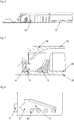
- Figure 1 shows with the reference numeral 10 a horizontal partition plate which separates two compartments of different temperatures within the cooled interior of a refrigerator or freezer from one another.
- the mist generator 20 is located in the separating plate 10 and is integrated in such a way that it is flush with the top of the separating plate 10.
- the mist generator does not protrude beyond the surface of the partition plate 10 on either side, i.e. not on the underside either.
- the partition plate has a thickness of 30 mm or less.
- the mist generator comprises the lid 30, the tank 40 and the receptacle 50, as shown in FIG Figure 2 a), b) and c) emerges.
- the cover 30 can be made in one or more parts. To fill the tank 40, it can be removed completely or just a part of it. A measuring cup can be arranged on the tank 30, preferably injection molded, which allows the tank to be filled more easily with water.
- the cover 30 could also be arranged on the tank so that it can be folded, pivoted or displaced.
- the cover 30 can contain means or be marked in such a way that these means or markings serve as fill level markings.
- the tank 40 is designed in such a way that its upper side can be completely covered by the cover 30.
- the tank has openings that prevent gas tightness, so that it is ensured that the mist can escape through the outlet openings of the tank 40.
- the tank has means for level detection, such as steps, colored markings, sprayed markings on the tank wall, float systems, etc.
- Figure 2 c shows the receptacle 50 for the tank 40 as well as the piezoelectric element, the piezo electronics for controlling it, cables, plugs, etc.
- the receptacle 50 preferably has all the elements required for operating the fog generator. This can be integrated into the horizontal separating plate 10, as is the case, for example, with an injection-molded part, or it can also be inserted into the separating plate 10 as an additional, ie as a separate part.
- Figure 3 illustrates the design of the smoke generator in a view from above at an angle without a cover.
- the reference numeral 100 shows the piezoelectronic which controls the piezoelectric element P.
- the concentrator which focuses the sound waves or water jets emanating from the piezoelectric element P like a lens onto a point or area is identified by the reference symbol K. From the concentrator K, the water or the mist reaches the deflecting element 90, which according to FIG Figure 4 can represent an integral part of the cover 30. From there the mist is directed into the nebulization chamber V, in which the mist is directed through the outlet openings 60 into the drawer or the like below the partition plate.
- Reference numeral 80 denotes means at the outlet openings which cause larger drops to fall back into the tank 40 and only fine drops to pass through the outlet openings 60.
- the reference numeral 70 denotes a wall or constriction which has the effect that the mist is pressed evenly through the outlet openings 60.
- Figure 4 shows the fog generator in a longitudinal sectional view and illustrates the arrangement of the concentrator K. This deflects the water jet or the sound waves that are excited by the piezoelectric element P.
- the shape of the concentrator can be parabolic, semicircular, circular or even just inclined.
- the concentrator K is preferably made of aluminum or another metal. Plastic or coated plastic or plastic equipped with metal or with a metallized film is also conceivable.
- the concentrator K is preferably dimensioned in such a way that only the water jet or sound wave coming from the piezoelectric element P is received. The advantage of the small size and the suitable dimension is that the water can easily get into the ram between the piezoelectric element and the concentrator K from all sides.
- the concentrator K and / or the piezoelectric element P is inclined towards the horizontal so that the water jet already points in the direction of the outlet openings or so that the water jet is directed in the direction of the outlet openings.
- the piezoelectric element P is inclined so that the obliquely aligned jet splits into droplets outside the water surface, so that the concentrator can be dispensed with.
- the invention also includes a non-planar design of the piezoelectric element, such as a parabolic shape, by means of which the distance between the piezoelectric element and the nebulization unit could be shortened.
- FIG Figure 6 shows a further sectional view and shows that the outlet openings 60 for the mist can have different heights.
- high channels can be used which delimit the outlet openings 60 and, with increasing distance from the piezoelectric element P, their height can decrease, as shown in FIG Figure 6 emerges.
- the water tank 40 and the nebulizer unit can form a common unit.
- the water tank 40 it is conceivable for the water tank 40 to be filled up to a maximum filling level and then to begin the nebulization, as a result of which the water level decreases.
- the piezoelectric element P is preferably designed in such a way that it is not damaged when it runs dry.
- the mist generator can be operated until the water is used up or is no longer sufficient to generate mist.
- the nebulizer unit shown can be separated into individual parts, ie the tank 40, the concentrator K and the deflector 90 can be removed without having to remove electrical components such as the piezoelectric element P or the piezoelectronics.
- the reference symbol O denotes an opening in the tank 40 in the region of the piezoelectric element P.
- Figure 8 shows the nebulizer unit, which is an integral part of the tank 40, in a view obliquely from above.
- the nebulizer unit consists of the nebulizer chamber V, the outlet openings 60, the concentrator K, which is optional, and the piezoelectric element P and its control.
- Figure 9 shows that when the tank 40 is removed for cleaning, for example by turning, tilting upwards or pushing it, an opening marked by the arrow is created, from which the residual water in the tank 40 drains can. All components below this point are preferably designed in such a way that a vessel can be placed underneath so that the water can be drained off.
- FIG 10 an embodiment can be seen in which the opening O according to Figure 7 is closed by a component B which has the property of transmitting the vibrations generated by the piezoelectric element P to the water in the tank 40.
- this part B prevents the residual water from flowing out of the tank 40 at this point, at least for a short time.
- a membrane can be used as component B, which allows a very small amount of water to be located between the piezoelectric element P and the membrane, so that the vibrations can be transmitted, but prevents water from leaking when the tank is removed becomes. The drop between the piezoelectric element and the membrane then drips, for example, into a drawer or the like, which is located below the mist generator, and evaporates there.
- component B can be arranged directly on piezoelectric element P.
- a porous material such as a sponge can also be used as component B. This absorbs water and enables the vibrations of the piezoelectric element to be transmitted, but prevents the tank from leaking out quickly.
- Figure 11 shows the path of the water inside the tank to the nebulizer unit by arrows.
Landscapes
- Engineering & Computer Science (AREA)
- Chemical & Material Sciences (AREA)
- Combustion & Propulsion (AREA)
- Physics & Mathematics (AREA)
- Mechanical Engineering (AREA)
- Thermal Sciences (AREA)
- General Engineering & Computer Science (AREA)
- Special Spraying Apparatus (AREA)
Description
- Die vorliegende Erfindung betrifft ein Kühl- und/oder Gefriergerät mit wenigstens einem Korpus und mit wenigstens einem von dem Korpus umgebenen gekühlten Innenraum, wobei in dem gekühlten Innenraum wenigstens einen Nebelerzeuger angeordnet ist, wobei der Nebelerzeuger wenigstens ein piezoelektrisches Element aufweist.
- Aus dem Stand der Technik ist es bekannt, in dem gekühlten Innenraum eines Kühl- bzw. Gefriergerätes einen Nebelerzeuger einzusetzen, der im Betrieb des piezoelektrischen Elementes aus einem Wasserreservoir Nebel bildet. Exemplarisch wird in diesem Zusammenhang auf die
DE 10 2014 017 044 A1 verwiesen, die ein solches Gerät offenbart. - Aus der
JP 2009 002590 A - Die
JP 2006 118825 A - Die
US 2010/223944 A1 offenbart einen Kühlschrank, der über eine Dampfsprühvorrichtung verfügt. Diese ist an einer vertikal verlaufenden Rückwand des Kühlschranks angeordnet. -
JP 2006 046768 A - Der vorliegenden Erfindung liegt die Aufgabe zugrunde, ein Kühl- und/oder Gefriergerät der eingangs genannten Art dahingehend weiterzubilden, dass dieses einen besonders kompakten Aufbau aufweist.
- Diese Aufgabe wird durch ein Kühl- und/oder Gefriergerät mit den Merkmalen des Anspruchs 1 gelöst.
- Erfindungsgemäß ist unter anderem vorgesehen, dass sich in dem gekühlten Innenraum wenigstens eine horizontale Trennplatte befindet, die den gekühlten Innenraum in zumindest zwei bei unterschiedlicher Temperatur betriebene Kompartimente trennt, wobei der Nebelerzeuger derart in die horizontale Trennplatte integriert ist, dass dieser nicht über die horizontale Trennplatte übersteht. Der Nebelerzeuger ist somit in die Trennplatte derart integriert, dass dieser zu keiner Seite über die Trennplatte übersteht, womit sich insgesamt eine besonders kompakte Bauweise ergibt und zudem der Vorteil eines besonders ansprechenden optischen Gesamteindrucks erzielt wird.
- In einer Ausführungsform die nicht unter der vorliegend beanspruchten Erfindung fällt ist jedoch auch ein gewisser Überstand des Nebelerzeugers an einer oder mehreren Seiten über die Oberfläche der Trennplatte hinaus umfasst. Vorzugsweise beträgt dieses Überstehen nicht mehr als 3 cm oder nicht mehr als 2 cm und besonders bevorzugt nicht mehr als 1 cm.
- Steht der Nebelerzeuger oben über die Trennplatte über, ist das Maß des Überstandes aufgrund der Einsehbarkeit des Überstandes durch den Nutzer vorzugsweise geringer (vorzugsweise maximal 1 cm), als bei einem Überstand auf der Unterseite der Trennplatte. Dort ist vorzugsweise ein maximaler Überstand von 2 cm vorgesehen.
- Befindet sich unterhalb der Trennplatte eine ausziehbare Schublade, ist vorzugsweise vorgesehen, dass sich der Nebelerzeuger - wenn überhaupt - auf der Unterseite nur so weit über die Trennplatte hinaus erstreckt, dass die Schublade ganz aus dem Gerät entnommen werden kann und der Nebelerzeuger keinen das Herausnehmen hindernden Anschlag bildet.
- In einer weiteren Ausgestaltung der Erfindung ist vorgesehen, dass der Nebelerzeuger aus mehreren modular zusammengesetzten Bestandteilen aufgebaut ist. Bei diesen Bestandteilen kann es sich beispielsweise um einen Tank und einen Deckel handeln, der relativ zu dem Tank verschiebbar, verschwenkbar oder abnehmbar sein kann.
- Unter dem Begriff "Bestandteil" können auch andere Elemente des Nebelerzeugers zu verstehen sein, wie beispielsweise ein oder mehrere Konzentratoren, die die Aufgabe haben, die von dem wenigstens einen piezoelektrischen Element ausgehenden Schallwellen bzw. Wasserstrahlen auf einem Punkt oder auf einen Bereich zu bündeln, oder ein oder mehrere Deflektoren, die die Aufgabe haben, die von dem wenigstens einen piezoelektrischen Element ausgehenden Schallwellen bzw. Wasserstrahlen umzulenken, oder auch Bestandteile der Elektronik, wie z.B. die Piezoelektronik zur Ansteuerung des piezoelektrischen Elementes.
- Eine Ausführungsform die nicht unter der vorliegend beanspruchten Erfindung fällt betrifft des Weiteren ein Kühl- und/oder Gefriergerät mit wenigstens einem von dem Korpus umgebenen gekühlten Innenraum, wobei in dem gekühlten Innenraum wenigstens einen Nebelerzeuger angeordnet ist, wobei der Nebelerzeuger wenigstens ein piezoelektrisches Element aufweist. In dieser Ausführungsform der Erfindung ist kein Konzentrator vorhanden ist, der die akustischen Wellen, die von dem piezoelektrischen Element ausgehen, fokussiert. Dadurch ergibt sich eine vergleichsweise konstruktiv einfache und kostengünstige Ausführung. Vorzugsweise ist in diesem Fall das piezoelektrische Element so geneigt, dass der von diesem ausgehende schräg verlaufende Wasserstrahl sich außerhalb der Wasseroberfläche in Tröpfchen aufteilt, so dass auf den Konzentrator verzichtet werden kann.
- Weiterhin kann vorgesehen sein, dass der Nebelerzeuger zumindest einen Tank und zumindest einen den Tank verschließenden Deckel sowie wenigstens eine Aufnahme für den Tank aufweist, wobei vorzugsweise vorgesehen ist, dass der Deckel relativ zu dem Tank bewegbar, vorzugsweise abnehmbar ist und/oder dass der Tank aus der Aufnahme entnehmbar ist. Durch die Entnehmbarkeit des Tanks kann dieser besonders einfach, z.B. in einer Spülmaschine gereinigt werden.
- Die Aufnahme kann einen festen bzw. integralen Bestandteil der Trennplatte oder eines sonstigen Elementes des Gerätes bilden oder ebenfalls lösbar im Gerät angeordnet sein.
- Erfindungsgemäß weist der Nebelerzeuger wenigstens eine Vernebelungskammer auf, die mehrere Auslassöffnungen für den erzeugten Nebel aufweist und dass mit zunehmendem Abstand von dem piezoelektrischen Element die Breite der Vernebelungskammer abnimmt. Durch diese Verengung kann eine Vergleichmäßigung der Verbreitung des Nebels durch die mehreren Auslassöffnungen erreicht werden.
- Vorzugsweise ist der Nebelerzeuger gemäß der vorliegenden Erfindung so angeordnet, dass der von diesem ausgehende Nebel in einem Bereich unterhalb des Nebelerzeugers "fällt" oder durch ein Gebläse oder Luftstrom gefördert wird. Bei diesem Bereich kann es sich beispielsweise um eine Schublade oder um ein sonstiges beliebiges Kompartiment handeln, das sich vorzugsweise unterhalb einer horizontalen Trennplatte befindet. Diese trennt in einer bevorzugten Ausgestaltung der Erfindung zwei Kompartimente voneinander, die im Betrieb des Gerätes bei unterschiedlichen Temperaturen betrieben werden, wie z.B. ein Kühlfach und ein Kaltlagerfach.
- Erfindungsgemäß weist der Nebelerzeuger wenigstens einen Konzentrator zur Fokussierung der von dem piezoelektrischen Element ausgehenden Schallwellen auf, wobei das piezoelektrische Element und/oder der Konzentrator zur Horizontalen hin geneigt ist. Auf diese Weise ist es möglich, den Wasserstrahl bzw. die Schallwellen in die gewünschte Richtung und vorzugsweise in Richtung der wenigstens einen Auslassöffnung des Nebelerzeugers zu lenken bzw. zu richten.
- Das piezoelektrische Element kann derart geneigt sein, dass sich außerhalb der Wasseroberfläche des in dem Tank befindlichen Wassers der durch das piezoelektrische Element erzeugte Wasserstrahl in Tröpfchen aufteilt.
- Nach der Erfindung weist der Nebelerzeuger wenigstens einen Deckel auf, wobei an dem Deckel wenigstens ein Umlenkelement vorgesehen ist, das den auf diesen treffenden und durch das piezoelektrische Element erzeugten Wasserstrahl in Richtung von einer oder mehreren Auslassöffnungen des Nebelerzeugers umlenkt. In diesem Fall kann auf ein separates Umlenkelement verzichtet werden, da dieses Bestandteil des Deckels und vorzugsweise ein integraler Bestandteil des Deckels ist.
- Denkbar ist es weiterhin, dass der Nebelerzeuger zumindest einen Wassertank aufweist, der derart geneigt ist, dass Wasser zu dem piezoelektrischen Element hin läuft. So ist sichergestellt, dass an dem piezoelektrischen Element stets ausreichend Wasser vorhanden ist, wenn der Tank eine ausreichende Füllung aufweist.
- Vorzugsweise ist vorgesehen, dass das piezoelektrische Element vollständig oder weitgehend mit Wasser bedeckt ist, wenn der Nebelerzeuger in Betrieb ist.
- Weiterhin ist es denkbar, dass der Nebelerzeuger zumindest einen Wassertank aufweist, der zumindest eine Öffnung zu dem piezoelektrischen Element umfasst, wobei diese Öffnung durch zumindest ein Schwingungen übertragendes Dichtungselement verschlossen ist. Dies bringt den Vorteil mit sich, dass bei der Entnahme des Tanks aus dem Nebelerzeuger kein restliches Wasser in den gekühlten Innenraum tropft, da diese von dem Dichtungselement überdeckt ist.
- Weitere Einzelheiten und Vorteile der Erfindung werden anhand eines in der Zeichnung dargestellten Ausführungsbeispiels näher erläutert.
- Es zeigen:
- Figur 1:
- eine perspektivische Draufsicht auf eine Trennplatte von schräg oben mit integriertem Nebelerzeuger,
- Figur 2:
- perspektivische Ansichten von Deckel, Tank und Aufnahme,
- Figur 3:
- eine perspektivische Draufsicht auf den Nebelerzeuger von schräg oben,
- Figur 4:
- eine Längsschnittansicht durch den Nebelerzeuger,
- Figur 5:
- eine Detailansicht im Schnitt durch den Nebelerzeuger im Bereich des piezoelektrischen Elementes in geneigter Ausführung,
- Figur 6:
- eine weitere Längsschnittansicht durch den Nebelerzeuger,
- Figur 7:
- eine Detailansicht im Schnitt durch den Nebelerzeuger im Bereich des piezoelektrischen Elementes,
- Figur 8:
- eine perspektivische Draufsicht auf den Tank mit Auslassöffnungen und Verneblereinheit,
- Figur 9:
- eine Detailansicht im Schnitt durch den Nebelerzeuger im Bereich des piezoelektrischen Elementes,
- Figur 10:
- eine Detailansicht im Schnitt durch den Nebelerzeuger im Bereich des piezoelektrischen Elementes mit Dichtungselement,
- Figur 11:
- eine perspektivische Draufsicht auf den Tank mit Auslassöffnungen und Verneblereinheit und Verdeutlichung des Verlaufs der Wasserströmung und
- Figur 12:
- eine schematische Ansicht der vernebelbaren Wassermenge im Tank.
-
Figur 1 zeigt mit dem Bezugszeichen 10 eine horizontale Trennplatte, die zwei Kompartimente unterschiedlicher Temperatur innerhalb des gekühlten Innenraum eines Kühl- bzw. Gefriergerätes voneinander trennt. - In der Trennplatte 10 befindet sich der Nebelerzeuger 20, der so integriert ist, dass dieser bündig mit der Oberseite der Trennplatte 10 abschließt. Der Nebelerzeuger steht an keiner Seite, d.h. auch nicht auf der Unterseite über die Oberfläche der Trennplatte 10 über. Vorzugsweise weist die Trennplatte eine Dicke von 30 mm oder weniger auf.
- Der Nebelerzeuger umfasst den Deckel 30, den Tank 40 und die Aufnahme 50, wie dies aus
Figur 2 a), b) und c) hervorgeht. - Der Deckel 30 kann ein- oder mehrteilig ausgeführt sein. Er kann zur Füllung des Tanks 40 komplett entnommen werden oder auch nur ein Teil von diesem. Am Tank 30 kann ein Messbecher angeordnet, vorzugsweise angespritzt sein, der eine einfachere Befüllung des Tanks mit Wasser erlaubt.
- Anstelle einer vollständigen Abnehmbarkeit könnte der Deckel 30 auch klapp- bzw. schwenkbar oder verschiebbar auf dem Tank angeordnet sein.
- Der Deckel 30 kann Mittel enthalten oder derart markiert sein, dass diese Mittel bzw. Markierungen als Füllstandsmarkierungen dienen.
- Der Tank 40 ist so gestaltet, dass dessen Oberseite vollständig von dem Deckel 30 abdeckbar ist. Der Tank weist Öffnungen auf, die Gasdichtheit verhindern, so dass sichergestellt ist, dass der Nebel durch die Auslassöffnungen des Tanks 40 entweichen kann. Der Tank weist Mittel zur Füllstandserkennung auf, wie z.B. Stufen, farbige Markierungen, gespritzte Markierungen an der Tankwand, Schwimmersysteme etc.
-
Figur 2 c) zeigt die Aufnahme 50 für den Tank 40 sowie das piezoelektrische Element, die Piezoelektronik zu dessen Ansteuerung, Kabel, Stecker etc. Die Aufnahme 50 weist vorzugsweise sämtliche zum Betrieb des Nebelerzeugers erforderlichen Elemente auf. Diese kann in die horizontale Trennplatte 10 integriert sein, wie dies z.B. bei einem Spritzgussteil der Fall ist, oder auch als zusätzliches, d.h. als separates Teil in die Trennplatte 10 eingesetzt sein. -
Figur 3 verdeutlicht die Ausgestaltung des Nebelerzeugers in einer Ansicht von schräg oben ohne Deckel. - Das Bezugszeichen 100 zeigt die Piezoelektronik, die das das piezoelektrische Element P ansteuert. Mit dem Bezugszeichen K ist der Konzentrator gekennzeichnet, der die von dem das piezoelektrischen Element P ausgehendenden Schallwellen bzw. Wasserstrahlen wie eine Linse auf einen Punkt oder Bereich fokussiert. Von dem Konzentrator K gelangt das Wasser bzw. der Nebel zu dem Umlenkelement 90, das gemäß
Figur 4 einen integralen Bestandteil des Deckels 30 darstellten kann. Von dort wird der Nebel in die Vernebelungskammer V geleitet, in der der Nebel durch die Auslassöffnungen 60 in die Schublade oder dergleichen unterhalb der Trennplatte gelenkt wird. - Das Bezugszeichen 80 kennzeichnet Mittel an den Auslassöffnungen, die bewirken, dass größere Tropfen in den Tank 40 zurückfallen und nur feine Tropfen durch die Auslassöffnungen 60 gelangen. Mit dem Bezugszeichen 70 ist eine Wandung bzw. Verengung gekennzeichnet, die bewirkt, dass der Nebel gleichmäßig durch die Auslassöffnungen 60 gedrückt wird.
-
Figur 4 zeigt den Nebelerzeuger in einer Längsschnittansicht und verdeutlicht die Anordnung des Konzentrators K. Dieser lenkt den Wasserstrahl bzw. die Schallwellen, die von dem piezoelektrischen Element P angeregt werden, um. Die Form des Konzentrators kann parabolisch, halbkreisförmig, kreisförmig oder auch nur schräg sein. - Der Konzentrator K besteht vorzugsweise aus Aluminium oder auch einem anderen Metall. Auch Kunststoff oder beschichteter Kunststoff oder mit Metall oder mit metallisierter Folie ausgestatteter Kunststoff ist denkbar. Vorzugsweise ist der Konzentrator K so dimensioniert, dass nur der von dem piezoelektrischen Element P kommende Wasserstrahl bzw. Schallwelle aufgenommen wird. Der Vorteil der geringen Größe und der geeigneten Dimension besteht darin, dass das Wasser gut von allen Seiten in den Ram zwischen dem piezoelektrischen Element und dem Konzentrator K gelangen kann.
- Erfindungsgemäß ist der Konzentrator K und/oder das piezoelektrische Element P zur Horizontalen hin geneigt, so dass der Wasserstrahl bereits in Richtung der Auslassöffnungen zeigt bzw. so dass der Wasserstrahl in Richtung der Auslassöffnungen gelenkt wird.
- Insbesondere ist eine Ausgestaltung denkbar, die nicht unter dem vorliegend beanspruchten Gegenstand fällt, bei der das piezoelektrische Element P so geneigt ist, dass der schräg ausgerichtete Strahl sich außerhalb der Wasseroberfläche in Tröpfchen teilt, so dass auf den Konzentrator verzichtet werden kann. Von der Erfindung ist auch eine nicht plane Ausführung des piezoelektrischen Elementes umfasst, wie beispielsweise eine parabolisch Form, durch die die Strecke zwischen dem piezoelektrischen Element und der Vernebelungseinheit verkürzen könnte.
-
Figur 6 zeigt eine weitere Schnittansicht und verdeutlicht, dass die Auslassöffnungen 60 für den Nebel verschiedene Höhen aufweisen können. Vorne, d.h. zu dem piezoelektrischen Element hin, können hohe Kanäle eingesetzt werden, die die Auslassöffnungen 60 begrenzen und mit zunehmender Entfernung von dem piezoelektrischen Element P kann deren Höhe geringer werden, wie dies ausFigur 6 hervorgeht. - Durch die ebenfalls aus
Figur 6 ersichtliche Schräge S im Boden des Wassertanks 40 wird erreicht, dass stets Wasser zu dem piezoelektrischen Element geleitet wird. Somit ist bei dieser Ausführung kein Ventil erforderlich. - Der Wassertank 40 und die Verneblereinheit können eine gemeinsame Einheit bilden.
- Denkbar ist es, denn Wassertank 40 bis zu einer maximalen Füllhöhe zu füllen und dann die Verneblung zu beginnen, wodurch der Wasserstand abnimmt. Vorzugsweise ist das piezoelektrische Element P so ausgebildet, dass dieses keinen Schaden nimmt, wenn es trockenläuft. Der Nebelerzeuger kann solange betrieben werden, bis das Wasser aufgebraucht ist bzw. zur Nebelerzeugung nicht mehr ausreicht.
- Auch ist eine Ausführung denkbar, bei der über ein Ventil bei Bedarf Wasser in den Tank 40 zuläuft und so ein konstanter Pegel an Wasser in dem Tank 40 sichergestellt wird.
- Vorzugsweise ist die in
Figur 7 gezeigte Verneblereinheit in Einzelteile trennbar, d.h. der Tank 40, der Konzentrator K und die Umlenkung 90 können entnommen werden, ohne dass elektrische Bauteile, wie das piezoelektrische Element P oder die Piezoelektronik entnommen werden müssen. Das Bezugszeichen O kennzeichnet eine Öffnung im Tank 40 im Bereich des piezoelektrischen Elementes P. -
Figur 8 zeigt die Verneblereinheit, die integraler Bestandteil des Tanks 40 ist in einer Ansicht von schräg oben. Die Verneblereinheit besteht aus der Verneblerkammer V, den Auslassöffnungen 60, dem Konzentrator K, der optional ist, und als dem piezoelektrischen Element P sowie seiner Steuerung. -
Figur 9 verdeutlicht, dass bei der Entnahme des Tanks 40 zur Reinigung z.B. durch Drehen, Kippen nach oben oder Schieben eine durch den Pfeil gekennzeichnete Öffnung entsteht, aus der das in dem Tank 40 befindliche Restwasser auslaufen kann. Vorzugsweise sind sämtliche Bauteile unterhalb von dieser Stelle so gestaltet, dass ein Gefäß untergestellt werden kann, so dass das Wasser abgelassen werden kann. - Aus
Figur 10 ist eine Ausführung ersichtlich, bei der die Öffnung O gemäßFigur 7 durch ein Bauteil B verschlossen ist, das die Eigenschaft aufweist, die durch das piezoelektrische Element P erzeugten Schwingungen an das Wasser zu übertragen, das sich in dem Tank 40 befindet. Dieses Teil B verhindert bei der Entnahme des Tanks 40 zumindest kurzzeitig, dass das Restwasser an dieser Stelle aus dem Tank 40 auslaufen kann. Als Bauteil B kann eine Membran verwendet werden, die es erlaubt, dass sich zwischen dem piezoelektrischen Element P und der Membran eine sehr geringe Menge an Wasser befindet, so dass die Schwingungen übertragen werden können, aber bei der Entnahme des Tanks ein Auslaufen von Wasser verhindert wird. Der Tropfen zwischen dem piezoelektrischen Element und der Membran tropft dann beispielsweise in eine Schublade oder dergleichen, die sich unterhalb des Nebelerzeugers befindet und verdunstet dort. Alternativ zu einer Anordnung am Tank ist es, das Bauteil B direkt auf dem piezoelektrischen Element P anzuordnen. - Anstelle einer Membran kann auch ein poröses Material, wie z.B. ein Schwamm als Bauteil B verwendet werden. Dieses nimmt Wasser auf und ermöglicht die Übertragung der Schwingungen des piezoelektrischen Elements, verhindert jedoch ein schnelles Auslaufen des Tanks.
-
Figur 11 verdeutlicht durch Pfeile den Weg des Wassers innerhalb des Tanks zu der Verneblereinheit. - Aus
Figur 12 ist schematisch ersichtlich, dass sich die vernebelbare Wassermenge W vorzugsweise 9 bis 14 mm oberhalb des Tankbodens befindet.
Claims (6)
- Kühl- und/oder Gefriergerät mit
einem Korpus, und
einem von dem Korpus umgebenen gekühlten Innenraum, wobei
in dem gekühlten Innenraum einen Nebelerzeuger (20) angeordnet ist, der ein piezoelektrisches Element (P) aufweist,
sich in dem gekühlten Innenraum eine horizontale Trennplatte (10) befindet, die den gekühlten Innenraum in zwei vorzugsweise bei unterschiedlicher Temperatur betriebene Kompartimente trennt, und
der Nebelerzeuger (20) derart in die horizontale Trennplatte (10) integriert ist, dass dieser nicht über die horizontale Trennplatte (10) übersteht,
dadurch gekennzeichnet, dass
der Nebelerzeuger (20) einen Deckel (30) aufweist, an dem ein Umlenkelement (90) vorgesehen ist, das den auf diesen treffenden und durch das piezoelektrische Element (P) erzeugten Wasserstrahl in Richtung einer Auslassöffnung (60) des Nebelerzeugers (20) umlenkt, wobei der Nebelerzeuger (20) wenigstens eine Vernebelungskammer (V) aufweist, die mehrere Auslassöffnungen (60) für den erzeugten Nebel aufweist, wobei mit zunehmendem Abstand von dem piezoelektrischen Element (P) die Breite der Vernebelungskammer (V) abnimmt, wobei der Nebelerzeuger (20) wenigstens einen Konzentrator (K) zur Fokussierung der von dem piezoelektrischen Element (P) ausgehenden Schallwellen aufweist und wobei das piezoelektrische Element (P) und/oder der Konzentrator (K) zur Horizontalen hin geneigt ist. - Kühl- und/oder Gefriergerät nach Anspruch 1, dadurch gekennzeichnet, dass der Nebelerzeuger (20) zumindest einen Tank (40) und zumindest einen den Tank (40) verschließenden Deckel (30) sowie wenigstens eine Aufnahme für den Tank (40) aufweist, wobei vorzugsweise vorgesehen ist, dass der Deckel (30) relativ zu dem Tank (40) bewegbar, vorzugsweise abnehmbar ist und/oder dass der Tank (40) aus der Aufnahme entnehmbar ist.
- Kühl- und/oder Gefriergerät nach Anspruch 1, dadurch gekennzeichnet, dass das piezoelektrische Element (P) derart geneigt ist, dass sich außerhalb der Wasseroberfläche des in dem Tank (40) befindlichen Wassers der durch das piezoelektrische Element (P) erzeugte Wasserstrahl in Tröpfchen aufteilt.
- Kühl- und/oder Gefriergerät nach einem der vorhergehenden Ansprüche, dadurch gekennzeichnet, dass der Nebelerzeuger (20) zumindest einen Wassertank (40) aufweist, der derart geneigt ist, dass Wasser zu dem piezoelektrischen Element (P) hin läuft.
- Kühl- und/oder Gefriergerät nach einem der vorhergehenden Ansprüche, dadurch gekennzeichnet, dass der Nebelerzeuger (20) zumindest einen Wassertank (40) aufweist, der zumindest eine Öffnung (O) zu dem piezoelektrischen Element (P) umfasst, wobei diese Öffnung (O) durch zumindest ein Schwingungen übertragendes Dichtungselement verschlossen ist.
- Kühl- und/oder Gefriergerät nach einem der vorhergehenden Ansprüche, dadurch gekennzeichnet, dass der Nebelerzeuger (20) aus mehreren modular zusammengesetzten Bestandteilen aufgebaut ist.
Applications Claiming Priority (2)
| Application Number | Priority Date | Filing Date | Title |
|---|---|---|---|
| DE102016004123 | 2016-04-05 | ||
| DE102016005405.0A DE102016005405A1 (de) | 2016-04-05 | 2016-05-02 | Kühl- und/oder Gefriergerät |
Publications (2)
| Publication Number | Publication Date |
|---|---|
| EP3228964A1 EP3228964A1 (de) | 2017-10-11 |
| EP3228964B1 true EP3228964B1 (de) | 2021-06-16 |
Family
ID=58428160
Family Applications (1)
| Application Number | Title | Priority Date | Filing Date |
|---|---|---|---|
| EP17162997.5A Active EP3228964B1 (de) | 2016-04-05 | 2017-03-27 | Kühl- und/oder gefriergerät |
Country Status (2)
| Country | Link |
|---|---|
| EP (1) | EP3228964B1 (de) |
| ES (1) | ES2886611T3 (de) |
Families Citing this family (1)
| Publication number | Priority date | Publication date | Assignee | Title |
|---|---|---|---|---|
| DE102021112317A1 (de) * | 2020-10-29 | 2022-05-05 | Liebherr-Hausgeräte Ochsenhausen GmbH | Vorrichtung zur Nebelerzeugung in einem Kühl- und/oder Gefriergerät |
Family Cites Families (10)
| Publication number | Priority date | Publication date | Assignee | Title |
|---|---|---|---|---|
| FR2690634B1 (fr) * | 1992-04-29 | 1994-10-14 | Chronotec | Dispositif de micro-pulvérisation générée par ondes ultra-sonores. |
| JP4468104B2 (ja) * | 2004-08-03 | 2010-05-26 | 株式会社東芝 | 冷蔵庫 |
| JP2006118825A (ja) * | 2004-10-25 | 2006-05-11 | Toshiba Corp | 冷蔵庫 |
| JP2007024421A (ja) * | 2005-07-19 | 2007-02-01 | Takagi Ind Co Ltd | ミスト発生方法及びその装置 |
| JP4962163B2 (ja) * | 2007-06-22 | 2012-06-27 | パナソニック株式会社 | 冷蔵庫および冷蔵庫に搭載される霧化装置 |
| BRPI0818294B1 (pt) * | 2007-10-09 | 2020-01-21 | Panasonic Corp | refrigerador e método de armazenamento no mesmo |
| FR3004971B1 (fr) * | 2013-04-30 | 2015-04-03 | Areco Finances Et Technologie Arfitec | Systeme de nebulisation pour rafraichir l'air |
| DE102013213206A1 (de) * | 2013-07-05 | 2015-01-08 | BSH Bosch und Siemens Hausgeräte GmbH | Haushaltskältegerät mit einem im Innenraum ausgebildeten Lagerbereich und einer Befeuchtungsvorrichtung |
| EP2876392B1 (de) | 2013-11-26 | 2021-01-06 | Liebherr-Hausgeräte Ochsenhausen GmbH | Kühl- und/oder gefriergerät |
| FR3023735B1 (fr) * | 2014-07-17 | 2016-07-29 | Areco Finances Et Tech - Arfitec | Nebuliseur compact pour rafraichir l'air |
-
2017
- 2017-03-27 EP EP17162997.5A patent/EP3228964B1/de active Active
- 2017-03-27 ES ES17162997T patent/ES2886611T3/es active Active
Non-Patent Citations (1)
| Title |
|---|
| None * |
Also Published As
| Publication number | Publication date |
|---|---|
| EP3228964A1 (de) | 2017-10-11 |
| ES2886611T3 (es) | 2021-12-20 |
Similar Documents
| Publication | Publication Date | Title |
|---|---|---|
| DE69327733T2 (de) | Ultraschall-vernebelungsvorrichtung | |
| DE112007000013B4 (de) | Dampfgenerator und Waschmaschine mit einem solchen | |
| DE69513094T2 (de) | Sprühvorrichtung, insbesondere zum Sprühen von Wasser in Mikrotropfenform, für eine nicht-stationäre Umgebung | |
| AT512219B1 (de) | Zerstäubungsvorrichtung | |
| EP1505891B1 (de) | Reinigungsvorrichtung für den scherkopf eines trockenrasierapparates | |
| DE102009015303A1 (de) | Vorrichtung zur Aufbringung eines kosmetischen Puders auf einem Schwamm | |
| DE102014013372A1 (de) | Zentrifugalwasserabscheider für ein brennstoffzellensystem | |
| DE102010037098A1 (de) | Endoskop mit einer Reinigungsdüse | |
| EP1598119A1 (de) | Ultraschallvernebelungsgerät sowie Verfahren zum Ultraschallvernebeln | |
| WO2009030382A1 (de) | Verfahren und vorrichtung zur reinigung von abgas | |
| DE2002056A1 (de) | Zerstaeubungskuehler,insbesondere Kuehlturm zur Abkuehlung von Wasser | |
| DE29910915U1 (de) | Flüssigkeitsgefüllter Dekorationsgegenstand mit einer Vorrichtung zur Erzeugung von Luftblasen | |
| DE20317601U1 (de) | Kondensationsvorrichtung für die Abluft eines Gargerätes | |
| EP3228965B1 (de) | Kühl- und/oder gefriergerät | |
| EP3228964A1 (de) | Kühl- und/oder gefriergerät | |
| DE102016009345A1 (de) | Kühl- und/oder Gefriergerät | |
| DE3126952A1 (de) | "nebelgenerator" | |
| EP3628163B1 (de) | Ablöschkasten für ein gargerät, gargerät mit einem ablöschkasten sowie verfahren zum steuern des druckaufbaus bei einem gargerät | |
| DE102016005405A1 (de) | Kühl- und/oder Gefriergerät | |
| DE9207238U1 (de) | Tragbares Gerät zum Verteilen befeuchteter und abgekühlter Luft | |
| DE102013004543B4 (de) | Ultraschall-Vernebelungsvorrichtung | |
| DE3109540A1 (de) | Dampfaustritt fuer ein dampfbad | |
| DE102006017488B3 (de) | Hub-Tauchanlage | |
| DE102013210481A1 (de) | Haushalts-Kühlgerät mit Befeuchtungseinrichtung | |
| DE102010026831A1 (de) | Abflussvorrichtung für einen Trockensieb-Reingiungskopf |
Legal Events
| Date | Code | Title | Description |
|---|---|---|---|
| PUAI | Public reference made under article 153(3) epc to a published international application that has entered the european phase |
Free format text: ORIGINAL CODE: 0009012 |
|
| STAA | Information on the status of an ep patent application or granted ep patent |
Free format text: STATUS: THE APPLICATION HAS BEEN PUBLISHED |
|
| AK | Designated contracting states |
Kind code of ref document: A1 Designated state(s): AL AT BE BG CH CY CZ DE DK EE ES FI FR GB GR HR HU IE IS IT LI LT LU LV MC MK MT NL NO PL PT RO RS SE SI SK SM TR |
|
| AX | Request for extension of the european patent |
Extension state: BA ME |
|
| STAA | Information on the status of an ep patent application or granted ep patent |
Free format text: STATUS: REQUEST FOR EXAMINATION WAS MADE |
|
| 17P | Request for examination filed |
Effective date: 20180411 |
|
| STAA | Information on the status of an ep patent application or granted ep patent |
Free format text: STATUS: EXAMINATION IS IN PROGRESS |
|
| 17Q | First examination report despatched |
Effective date: 20190402 |
|
| GRAP | Despatch of communication of intention to grant a patent |
Free format text: ORIGINAL CODE: EPIDOSNIGR1 |
|
| STAA | Information on the status of an ep patent application or granted ep patent |
Free format text: STATUS: GRANT OF PATENT IS INTENDED |
|
| INTG | Intention to grant announced |
Effective date: 20210121 |
|
| GRAS | Grant fee paid |
Free format text: ORIGINAL CODE: EPIDOSNIGR3 |
|
| GRAA | (expected) grant |
Free format text: ORIGINAL CODE: 0009210 |
|
| STAA | Information on the status of an ep patent application or granted ep patent |
Free format text: STATUS: THE PATENT HAS BEEN GRANTED |
|
| AK | Designated contracting states |
Kind code of ref document: B1 Designated state(s): AL AT BE BG CH CY CZ DE DK EE ES FI FR GB GR HR HU IE IS IT LI LT LU LV MC MK MT NL NO PL PT RO RS SE SI SK SM TR |
|
| REG | Reference to a national code |
Ref country code: GB Ref legal event code: FG4D Free format text: NOT ENGLISH |
|
| REG | Reference to a national code |
Ref country code: CH Ref legal event code: EP |
|
| REG | Reference to a national code |
Ref country code: DE Ref legal event code: R096 Ref document number: 502017010646 Country of ref document: DE |
|
| REG | Reference to a national code |
Ref country code: AT Ref legal event code: REF Ref document number: 1402669 Country of ref document: AT Kind code of ref document: T Effective date: 20210715 |
|
| REG | Reference to a national code |
Ref country code: IE Ref legal event code: FG4D Free format text: LANGUAGE OF EP DOCUMENT: GERMAN |
|
| REG | Reference to a national code |
Ref country code: LT Ref legal event code: MG9D |
|
| PG25 | Lapsed in a contracting state [announced via postgrant information from national office to epo] |
Ref country code: FI Free format text: LAPSE BECAUSE OF FAILURE TO SUBMIT A TRANSLATION OF THE DESCRIPTION OR TO PAY THE FEE WITHIN THE PRESCRIBED TIME-LIMIT Effective date: 20210616 Ref country code: LT Free format text: LAPSE BECAUSE OF FAILURE TO SUBMIT A TRANSLATION OF THE DESCRIPTION OR TO PAY THE FEE WITHIN THE PRESCRIBED TIME-LIMIT Effective date: 20210616 Ref country code: HR Free format text: LAPSE BECAUSE OF FAILURE TO SUBMIT A TRANSLATION OF THE DESCRIPTION OR TO PAY THE FEE WITHIN THE PRESCRIBED TIME-LIMIT Effective date: 20210616 Ref country code: BG Free format text: LAPSE BECAUSE OF FAILURE TO SUBMIT A TRANSLATION OF THE DESCRIPTION OR TO PAY THE FEE WITHIN THE PRESCRIBED TIME-LIMIT Effective date: 20210916 |
|
| REG | Reference to a national code |
Ref country code: NL Ref legal event code: MP Effective date: 20210616 |
|
| PG25 | Lapsed in a contracting state [announced via postgrant information from national office to epo] |
Ref country code: LV Free format text: LAPSE BECAUSE OF FAILURE TO SUBMIT A TRANSLATION OF THE DESCRIPTION OR TO PAY THE FEE WITHIN THE PRESCRIBED TIME-LIMIT Effective date: 20210616 Ref country code: GR Free format text: LAPSE BECAUSE OF FAILURE TO SUBMIT A TRANSLATION OF THE DESCRIPTION OR TO PAY THE FEE WITHIN THE PRESCRIBED TIME-LIMIT Effective date: 20210917 Ref country code: NO Free format text: LAPSE BECAUSE OF FAILURE TO SUBMIT A TRANSLATION OF THE DESCRIPTION OR TO PAY THE FEE WITHIN THE PRESCRIBED TIME-LIMIT Effective date: 20210916 Ref country code: SE Free format text: LAPSE BECAUSE OF FAILURE TO SUBMIT A TRANSLATION OF THE DESCRIPTION OR TO PAY THE FEE WITHIN THE PRESCRIBED TIME-LIMIT Effective date: 20210616 Ref country code: RS Free format text: LAPSE BECAUSE OF FAILURE TO SUBMIT A TRANSLATION OF THE DESCRIPTION OR TO PAY THE FEE WITHIN THE PRESCRIBED TIME-LIMIT Effective date: 20210616 |
|
| REG | Reference to a national code |
Ref country code: ES Ref legal event code: FG2A Ref document number: 2886611 Country of ref document: ES Kind code of ref document: T3 Effective date: 20211220 |
|
| PG25 | Lapsed in a contracting state [announced via postgrant information from national office to epo] |
Ref country code: SM Free format text: LAPSE BECAUSE OF FAILURE TO SUBMIT A TRANSLATION OF THE DESCRIPTION OR TO PAY THE FEE WITHIN THE PRESCRIBED TIME-LIMIT Effective date: 20210616 Ref country code: SK Free format text: LAPSE BECAUSE OF FAILURE TO SUBMIT A TRANSLATION OF THE DESCRIPTION OR TO PAY THE FEE WITHIN THE PRESCRIBED TIME-LIMIT Effective date: 20210616 Ref country code: EE Free format text: LAPSE BECAUSE OF FAILURE TO SUBMIT A TRANSLATION OF THE DESCRIPTION OR TO PAY THE FEE WITHIN THE PRESCRIBED TIME-LIMIT Effective date: 20210616 Ref country code: CZ Free format text: LAPSE BECAUSE OF FAILURE TO SUBMIT A TRANSLATION OF THE DESCRIPTION OR TO PAY THE FEE WITHIN THE PRESCRIBED TIME-LIMIT Effective date: 20210616 Ref country code: RO Free format text: LAPSE BECAUSE OF FAILURE TO SUBMIT A TRANSLATION OF THE DESCRIPTION OR TO PAY THE FEE WITHIN THE PRESCRIBED TIME-LIMIT Effective date: 20210616 Ref country code: PT Free format text: LAPSE BECAUSE OF FAILURE TO SUBMIT A TRANSLATION OF THE DESCRIPTION OR TO PAY THE FEE WITHIN THE PRESCRIBED TIME-LIMIT Effective date: 20211018 Ref country code: NL Free format text: LAPSE BECAUSE OF FAILURE TO SUBMIT A TRANSLATION OF THE DESCRIPTION OR TO PAY THE FEE WITHIN THE PRESCRIBED TIME-LIMIT Effective date: 20210616 |
|
| PG25 | Lapsed in a contracting state [announced via postgrant information from national office to epo] |
Ref country code: PL Free format text: LAPSE BECAUSE OF FAILURE TO SUBMIT A TRANSLATION OF THE DESCRIPTION OR TO PAY THE FEE WITHIN THE PRESCRIBED TIME-LIMIT Effective date: 20210616 |
|
| REG | Reference to a national code |
Ref country code: DE Ref legal event code: R097 Ref document number: 502017010646 Country of ref document: DE |
|
| PLBE | No opposition filed within time limit |
Free format text: ORIGINAL CODE: 0009261 |
|
| STAA | Information on the status of an ep patent application or granted ep patent |
Free format text: STATUS: NO OPPOSITION FILED WITHIN TIME LIMIT |
|
| PG25 | Lapsed in a contracting state [announced via postgrant information from national office to epo] |
Ref country code: DK Free format text: LAPSE BECAUSE OF FAILURE TO SUBMIT A TRANSLATION OF THE DESCRIPTION OR TO PAY THE FEE WITHIN THE PRESCRIBED TIME-LIMIT Effective date: 20210616 |
|
| 26N | No opposition filed |
Effective date: 20220317 |
|
| PG25 | Lapsed in a contracting state [announced via postgrant information from national office to epo] |
Ref country code: AL Free format text: LAPSE BECAUSE OF FAILURE TO SUBMIT A TRANSLATION OF THE DESCRIPTION OR TO PAY THE FEE WITHIN THE PRESCRIBED TIME-LIMIT Effective date: 20210616 |
|
| PG25 | Lapsed in a contracting state [announced via postgrant information from national office to epo] |
Ref country code: MC Free format text: LAPSE BECAUSE OF FAILURE TO SUBMIT A TRANSLATION OF THE DESCRIPTION OR TO PAY THE FEE WITHIN THE PRESCRIBED TIME-LIMIT Effective date: 20210616 |
|
| REG | Reference to a national code |
Ref country code: CH Ref legal event code: PL |
|
| GBPC | Gb: european patent ceased through non-payment of renewal fee |
Effective date: 20220327 |
|
| REG | Reference to a national code |
Ref country code: BE Ref legal event code: MM Effective date: 20220331 |
|
| PG25 | Lapsed in a contracting state [announced via postgrant information from national office to epo] |
Ref country code: LU Free format text: LAPSE BECAUSE OF NON-PAYMENT OF DUE FEES Effective date: 20220327 Ref country code: LI Free format text: LAPSE BECAUSE OF NON-PAYMENT OF DUE FEES Effective date: 20220331 Ref country code: IE Free format text: LAPSE BECAUSE OF NON-PAYMENT OF DUE FEES Effective date: 20220327 Ref country code: GB Free format text: LAPSE BECAUSE OF NON-PAYMENT OF DUE FEES Effective date: 20220327 Ref country code: CH Free format text: LAPSE BECAUSE OF NON-PAYMENT OF DUE FEES Effective date: 20220331 |
|
| PG25 | Lapsed in a contracting state [announced via postgrant information from national office to epo] |
Ref country code: BE Free format text: LAPSE BECAUSE OF NON-PAYMENT OF DUE FEES Effective date: 20220331 |
|
| REG | Reference to a national code |
Ref country code: AT Ref legal event code: MM01 Ref document number: 1402669 Country of ref document: AT Kind code of ref document: T Effective date: 20220327 |
|
| P01 | Opt-out of the competence of the unified patent court (upc) registered |
Effective date: 20230530 |
|
| PG25 | Lapsed in a contracting state [announced via postgrant information from national office to epo] |
Ref country code: AT Free format text: LAPSE BECAUSE OF NON-PAYMENT OF DUE FEES Effective date: 20220327 |
|
| PG25 | Lapsed in a contracting state [announced via postgrant information from national office to epo] |
Ref country code: HU Free format text: LAPSE BECAUSE OF FAILURE TO SUBMIT A TRANSLATION OF THE DESCRIPTION OR TO PAY THE FEE WITHIN THE PRESCRIBED TIME-LIMIT; INVALID AB INITIO Effective date: 20170327 |
|
| PG25 | Lapsed in a contracting state [announced via postgrant information from national office to epo] |
Ref country code: MK Free format text: LAPSE BECAUSE OF FAILURE TO SUBMIT A TRANSLATION OF THE DESCRIPTION OR TO PAY THE FEE WITHIN THE PRESCRIBED TIME-LIMIT Effective date: 20210616 Ref country code: CY Free format text: LAPSE BECAUSE OF FAILURE TO SUBMIT A TRANSLATION OF THE DESCRIPTION OR TO PAY THE FEE WITHIN THE PRESCRIBED TIME-LIMIT Effective date: 20210616 |
|
| PG25 | Lapsed in a contracting state [announced via postgrant information from national office to epo] |
Ref country code: MT Free format text: LAPSE BECAUSE OF FAILURE TO SUBMIT A TRANSLATION OF THE DESCRIPTION OR TO PAY THE FEE WITHIN THE PRESCRIBED TIME-LIMIT Effective date: 20210616 |
|
| PGFP | Annual fee paid to national office [announced via postgrant information from national office to epo] |
Ref country code: DE Payment date: 20250331 Year of fee payment: 9 |
|
| PGFP | Annual fee paid to national office [announced via postgrant information from national office to epo] |
Ref country code: ES Payment date: 20250401 Year of fee payment: 9 |
|
| PGFP | Annual fee paid to national office [announced via postgrant information from national office to epo] |
Ref country code: IT Payment date: 20250327 Year of fee payment: 9 |
|
| PG25 | Lapsed in a contracting state [announced via postgrant information from national office to epo] |
Ref country code: TR Free format text: LAPSE BECAUSE OF FAILURE TO SUBMIT A TRANSLATION OF THE DESCRIPTION OR TO PAY THE FEE WITHIN THE PRESCRIBED TIME-LIMIT Effective date: 20210616 |
|
| PGFP | Annual fee paid to national office [announced via postgrant information from national office to epo] |
Ref country code: FR Payment date: 20260330 Year of fee payment: 10 |