EP3229140A1 - Datenverarbeitungsvorrichtung und datenverarbeitungsverfahren - Google Patents
Datenverarbeitungsvorrichtung und datenverarbeitungsverfahren Download PDFInfo
- Publication number
- EP3229140A1 EP3229140A1 EP17151712.1A EP17151712A EP3229140A1 EP 3229140 A1 EP3229140 A1 EP 3229140A1 EP 17151712 A EP17151712 A EP 17151712A EP 3229140 A1 EP3229140 A1 EP 3229140A1
- Authority
- EP
- European Patent Office
- Prior art keywords
- data
- storage unit
- volatile storage
- memory
- log file
- Prior art date
- Legal status (The legal status is an assumption and is not a legal conclusion. Google has not performed a legal analysis and makes no representation as to the accuracy of the status listed.)
- Granted
Links
Images





Classifications
-
- G—PHYSICS
- G06—COMPUTING OR CALCULATING; COUNTING
- G06F—ELECTRIC DIGITAL DATA PROCESSING
- G06F3/00—Input arrangements for transferring data to be processed into a form capable of being handled by the computer; Output arrangements for transferring data from processing unit to output unit, e.g. interface arrangements
- G06F3/06—Digital input from, or digital output to, record carriers, e.g. RAID, emulated record carriers or networked record carriers
- G06F3/0601—Interfaces specially adapted for storage systems
- G06F3/0602—Interfaces specially adapted for storage systems specifically adapted to achieve a particular effect
- G06F3/0614—Improving the reliability of storage systems
- G06F3/0619—Improving the reliability of storage systems in relation to data integrity, e.g. data losses, bit errors
-
- G—PHYSICS
- G06—COMPUTING OR CALCULATING; COUNTING
- G06F—ELECTRIC DIGITAL DATA PROCESSING
- G06F11/00—Error detection; Error correction; Monitoring
- G06F11/07—Responding to the occurrence of a fault, e.g. fault tolerance
- G06F11/14—Error detection or correction of the data by redundancy in operations
- G06F11/1471—Error detection or correction of the data by redundancy in operations involving logging of persistent data for recovery
-
- G—PHYSICS
- G06—COMPUTING OR CALCULATING; COUNTING
- G06F—ELECTRIC DIGITAL DATA PROCESSING
- G06F11/00—Error detection; Error correction; Monitoring
- G06F11/07—Responding to the occurrence of a fault, e.g. fault tolerance
- G06F11/14—Error detection or correction of the data by redundancy in operations
- G06F11/1446—Point-in-time backing up or restoration of persistent data
- G06F11/1456—Hardware arrangements for backup
-
- G—PHYSICS
- G06—COMPUTING OR CALCULATING; COUNTING
- G06F—ELECTRIC DIGITAL DATA PROCESSING
- G06F11/00—Error detection; Error correction; Monitoring
- G06F11/07—Responding to the occurrence of a fault, e.g. fault tolerance
- G06F11/14—Error detection or correction of the data by redundancy in operations
- G06F11/1446—Point-in-time backing up or restoration of persistent data
- G06F11/1458—Management of the backup or restore process
- G06F11/1469—Backup restoration techniques
-
- G—PHYSICS
- G06—COMPUTING OR CALCULATING; COUNTING
- G06F—ELECTRIC DIGITAL DATA PROCESSING
- G06F11/00—Error detection; Error correction; Monitoring
- G06F11/07—Responding to the occurrence of a fault, e.g. fault tolerance
- G06F11/16—Error detection or correction of the data by redundancy in hardware
- G06F11/1608—Error detection by comparing the output signals of redundant hardware
- G06F11/1612—Error detection by comparing the output signals of redundant hardware where the redundant component is persistent storage
-
- G—PHYSICS
- G06—COMPUTING OR CALCULATING; COUNTING
- G06F—ELECTRIC DIGITAL DATA PROCESSING
- G06F3/00—Input arrangements for transferring data to be processed into a form capable of being handled by the computer; Output arrangements for transferring data from processing unit to output unit, e.g. interface arrangements
- G06F3/06—Digital input from, or digital output to, record carriers, e.g. RAID, emulated record carriers or networked record carriers
- G06F3/0601—Interfaces specially adapted for storage systems
- G06F3/0602—Interfaces specially adapted for storage systems specifically adapted to achieve a particular effect
- G06F3/061—Improving I/O performance
- G06F3/0611—Improving I/O performance in relation to response time
-
- G—PHYSICS
- G06—COMPUTING OR CALCULATING; COUNTING
- G06F—ELECTRIC DIGITAL DATA PROCESSING
- G06F3/00—Input arrangements for transferring data to be processed into a form capable of being handled by the computer; Output arrangements for transferring data from processing unit to output unit, e.g. interface arrangements
- G06F3/06—Digital input from, or digital output to, record carriers, e.g. RAID, emulated record carriers or networked record carriers
- G06F3/0601—Interfaces specially adapted for storage systems
- G06F3/0602—Interfaces specially adapted for storage systems specifically adapted to achieve a particular effect
- G06F3/0614—Improving the reliability of storage systems
-
- G—PHYSICS
- G06—COMPUTING OR CALCULATING; COUNTING
- G06F—ELECTRIC DIGITAL DATA PROCESSING
- G06F3/00—Input arrangements for transferring data to be processed into a form capable of being handled by the computer; Output arrangements for transferring data from processing unit to output unit, e.g. interface arrangements
- G06F3/06—Digital input from, or digital output to, record carriers, e.g. RAID, emulated record carriers or networked record carriers
- G06F3/0601—Interfaces specially adapted for storage systems
- G06F3/0628—Interfaces specially adapted for storage systems making use of a particular technique
- G06F3/0638—Organizing or formatting or addressing of data
- G06F3/0643—Management of files
-
- G—PHYSICS
- G06—COMPUTING OR CALCULATING; COUNTING
- G06F—ELECTRIC DIGITAL DATA PROCESSING
- G06F3/00—Input arrangements for transferring data to be processed into a form capable of being handled by the computer; Output arrangements for transferring data from processing unit to output unit, e.g. interface arrangements
- G06F3/06—Digital input from, or digital output to, record carriers, e.g. RAID, emulated record carriers or networked record carriers
- G06F3/0601—Interfaces specially adapted for storage systems
- G06F3/0628—Interfaces specially adapted for storage systems making use of a particular technique
- G06F3/0646—Horizontal data movement in storage systems, i.e. moving data in between storage devices or systems
- G06F3/065—Replication mechanisms
-
- G—PHYSICS
- G06—COMPUTING OR CALCULATING; COUNTING
- G06F—ELECTRIC DIGITAL DATA PROCESSING
- G06F3/00—Input arrangements for transferring data to be processed into a form capable of being handled by the computer; Output arrangements for transferring data from processing unit to output unit, e.g. interface arrangements
- G06F3/06—Digital input from, or digital output to, record carriers, e.g. RAID, emulated record carriers or networked record carriers
- G06F3/0601—Interfaces specially adapted for storage systems
- G06F3/0668—Interfaces specially adapted for storage systems adopting a particular infrastructure
- G06F3/0671—In-line storage system
- G06F3/0683—Plurality of storage devices
-
- G—PHYSICS
- G06—COMPUTING OR CALCULATING; COUNTING
- G06F—ELECTRIC DIGITAL DATA PROCESSING
- G06F2201/00—Indexing scheme relating to error detection, to error correction, and to monitoring
- G06F2201/82—Solving problems relating to consistency
-
- G—PHYSICS
- G06—COMPUTING OR CALCULATING; COUNTING
- G06F—ELECTRIC DIGITAL DATA PROCESSING
- G06F2201/00—Indexing scheme relating to error detection, to error correction, and to monitoring
- G06F2201/85—Active fault masking without idle spares
-
- Y—GENERAL TAGGING OF NEW TECHNOLOGICAL DEVELOPMENTS; GENERAL TAGGING OF CROSS-SECTIONAL TECHNOLOGIES SPANNING OVER SEVERAL SECTIONS OF THE IPC; TECHNICAL SUBJECTS COVERED BY FORMER USPC CROSS-REFERENCE ART COLLECTIONS [XRACs] AND DIGESTS
- Y02—TECHNOLOGIES OR APPLICATIONS FOR MITIGATION OR ADAPTATION AGAINST CLIMATE CHANGE
- Y02D—CLIMATE CHANGE MITIGATION TECHNOLOGIES IN INFORMATION AND COMMUNICATION TECHNOLOGIES [ICT], I.E. INFORMATION AND COMMUNICATION TECHNOLOGIES AIMING AT THE REDUCTION OF THEIR OWN ENERGY USE
- Y02D10/00—Energy efficient computing, e.g. low power processors, power management or thermal management
Definitions
- the present invention relates to the field of information technologies, and in particular, to a data processing method and a data processing device.
- Improving a data read/write speed of a memory is one of factors that improve the service processing speed of the server.
- the data in the memory is lost upon an abnormal power failure or restart.
- a non-volatile storage medium is used to back up the data in the memory to ensure security of the data in the memory. When the data in the memory is lost, the data lost from the memory can be recovered.
- the non-volatile storage medium can permanently save the data, and the data is still not lost even in the case of a power failure.
- a data access speed of a large-capacity non-volatile storage medium is slow, but the data access speed of the memory is fast. If a scenario in which the data is lost from the memory occurs during a process of writing data in the memory into the non-volatile storage medium for backup, the data that is not backed up in a timely manner cannot be recovered. As a result, the security of the data in the memory cannot be ensured.
- Embodiments of the present invention provide a data processing device and a data processing method, to solve a problem that data backup fails due to a low data backup speed when data is written into a memory in an abnormal situation, resulting in a fact that security of the data in the memory is not high.
- An embodiment of the present invention provides a data processing device, where the data processing device includes a control unit, a memory, a first non-volatile storage unit, and a second non-volatile storage unit; a data write speed of the first non-volatile storage unit is higher than a data write speed of the second non-volatile storage unit; and the control unit is configured to write first data into the memory, write the first data into the first non-volatile storage unit in a log file form, and write, into the second non-volatile storage unit, a log file of the first data written into the first non-volatile storage unit.
- control unit includes a memory read/write control unit and a persistency control unit, where the memory read/write control unit is configured to write the first data into the memory, and write the first data into the first non-volatile storage unit in the log file form; and the persistency control unit is configured to write, into the second non-volatile storage unit, the log file of the first data written into the first non-volatile storage unit.
- the memory read/write control unit is further configured to write second data into the memory, and write the second data into the first non-volatile storage unit in the log file form.
- the persistency control unit is further configured to acquire the first data from the memory and write the first data into the second non-volatile storage unit.
- control unit further includes a data scrubbing unit, where the data scrubbing unit is configured to convert the log file of the first data in the second non-volatile storage unit to the first data.
- control unit further includes a data recovery unit, where the data recovery unit is configured to recover the first data lost from the memory by using the first data in the second non-volatile storage unit.
- the data recovery unit is further configured to recover the first data lost from the memory by using the log file of the first data in the second non-volatile storage unit, and recover the second data lost from the memory by using a log file of the second data in the first non-volatile storage unit.
- the data recovery unit is further configured to recover the first data lost from the memory by using the first data in the second non-volatile storage unit, and recover the second data lost from the memory by using a log file of the second data in the first non-volatile storage unit.
- the data recovery unit is further configured to recover the first data lost from the memory by using the first data and the log file of the first data in the second non-volatile storage unit, and recover the second data lost from the memory by using a log file of the second data in the first non-volatile storage unit.
- the persistency control unit is further configured to: after the log file of the first data in the first non-volatile storage unit is written into the second non-volatile storage unit, instruct the first non-volatile storage unit to release space occupied by the log file of the first data.
- the persistency control unit is further configured to: when the memory read/write control unit writes the second data into the first non-volatile storage unit, suspend writing the log file of the first data in the first non-volatile storage unit into the second non-volatile storage unit.
- the data write speed of the first non-volatile storage unit is the same as a data write speed of the memory.
- An embodiment of the present invention further provides a data processing device, where the data processing device includes a control unit, a memory, a first non-volatile storage unit, and a second non-volatile storage unit; a data write speed of the first non-volatile storage unit is higher than a data write speed of the second non-volatile storage unit; and the control unit is configured to write first data into the memory, and write the first data into the first non-volatile storage unit in a log file form; and the control unit is further configured to acquire the first data from the memory, and convert the acquired first data to a log file and write the converted log file into the second non-volatile storage unit.
- control unit includes a memory read/write control unit and a persistency control unit, where the memory read/write control unit is configured to write the first data into the memory, and write the first data into the first non-volatile storage unit in the log file form; and the persistency control unit is configured to acquire the first data from the memory, and convert the acquired first data to a log file and write the converted log file into the second non-volatile storage unit.
- the memory read/write control unit is further configured to write second data into the memory, and write the second data into the first non-volatile storage unit in the log file form.
- the persistency control unit is further configured to acquire the first data from the memory and write the first data into the second non-volatile storage unit.
- control unit further includes a data scrubbing unit, where the data scrubbing unit is configured to convert the log file of the first data in the second non-volatile storage unit to the first data.
- control unit further includes a data recovery unit, where the data recovery unit is configured to recover the first data lost from the memory by using the first data in the second non-volatile storage unit.
- the data recovery unit is further configured to recover the first data lost from the memory by using the log file of the first data in the second non-volatile storage unit, and recover the second data lost from the memory by using a log file of the second data in the first non-volatile storage unit.
- the data recovery unit is further configured to recover the first data lost from the memory by using the first data in the second non-volatile storage unit, and recover the second data lost from the memory by using a log file of the second data in the first non-volatile storage unit.
- the data recovery unit is further configured to recover the first data lost from the memory by using the first data and the log file of the first data in the second non-volatile storage unit, and recover the second data lost from the memory by using a log file of the second data in the first non-volatile storage unit.
- the data write speed of the first non-volatile storage unit is the same as a data write speed of the memory.
- An embodiment of the present invention further provides a data processing device, where the data processing device includes a control unit, a memory, a first non-volatile storage unit, and a second non-volatile storage unit; a data write speed of the first non-volatile storage unit is higher than a data write speed of the second non-volatile storage unit; and the control unit is configured to write first data into the memory, write the first data into the first non-volatile storage unit in a log file form, and write, into the second non-volatile storage unit, the first data in the memory.
- control unit includes a memory read/write control unit and a persistency control unit, where the memory read/write control unit is configured to write the first data into the memory, and write the first data into the first non-volatile storage unit in the log file form; and the persistency control unit is configured to write, into the second non-volatile storage unit, the first data in the memory.
- the memory read/write control unit is further configured to write second data into the memory, and write the second data into the first non-volatile storage unit in the log file form.
- control unit further includes a data recovery unit, where the data recovery unit is configured to recover the first data lost from the memory by using the first data in the second non-volatile storage unit.
- An embodiment of the present invention provides a data processing method, where the data processing method is applied in a data processing device and the data processing method includes:
- the method further includes:
- the method further includes: acquiring the first data from the memory and writing the first data into the second non-volatile storage unit.
- the method further includes: converting the log file of the first data in the second non-volatile storage unit to the first data.
- the recovering the first data lost from the memory by using the first data in the second non-volatile storage unit includes:
- the data write speed of the first non-volatile storage unit is the same as a data write speed of the memory.
- An embodiment of the present invention further provides another data processing method, where the data processing method is applied in a data processing device and the data processing method includes:
- the method further includes:
- the writing, into a second non-volatile storage unit, the first data written into the memory includes:
- the method further includes:
- the first data in the memory when the first data in the memory is lost, if the first data is stored in the second non-volatile storage unit, recovering the first data by using the first data in the second non-volatile storage unit; if only the log file of the first data is stored in the second non-volatile storage unit, recovering the first data lost from the memory by using the log file of the first data; and if the first data in the memory is lost during a process of converting the log file of the first data in the second non-volatile storage unit to the first data, recovering the first data in the memory by using converted first data and the log file of the first data that is not converted.
- the recovering the first data lost from the memory by using the first data in the second non-volatile storage unit includes:
- the data write speed of the first non-volatile storage unit is the same as a data write speed of the memory.
- An embodiment of the present invention further provides a data processing method, where the data processing method is applied in a data processing device and the data processing method includes:
- the method further includes:
- the method further includes:
- the method further includes:
- the recovering the first data lost from the memory by using the first data in the second non-volatile storage unit includes:
- the data write speed of the first non-volatile storage unit is the same as a data write speed of the memory.
- An embodiment of the present invention further provides a data processing method, where the data processing method is applied in a data processing device and the data processing method includes:
- the data write speed of the first non-volatile storage unit is the same as a data write speed of the memory.
- the first data written into the memory is written into the first non-volatile storage unit in the log file form, and the log file of the first data written into the first non-volatile storage unit is written into the second non-volatile storage unit. Because the data write speed of the first non-volatile storage unit is higher than the data write speed of the second non-volatile storage unit, fast backup of the data in the memory can be achieved, and when the data in the memory is lost in an abnormal situation, security of the data in the memory can be ensured.
- FIG. 1 is a schematic structural diagram of a data processing device 100 according to an embodiment of the present invention.
- the data processing device 100 includes a memory 101, a control unit 102, a first non-volatile storage unit 103, and a second non-volatile storage unit 104; a data write speed of the first non-volatile storage unit 103 is higher than a data write speed of the second non-volatile storage unit 104; and the control unit 102 is configured to write first data into the memory 101, write the first data into the first non-volatile storage unit 103 in a log file form, and write, into the second non-volatile storage unit 104, a log file of the first data written into the first non-volatile storage unit 103.
- the control unit 102 writes, into the first non-volatile storage unit 103 in the log file form, the first data written into the memory 101, and writes, into the second non-volatile storage unit 104, the log file of the first data written into the first non-volatile storage unit 103. Because the data write speed of the first non-volatile storage unit 103 is higher than the data write speed of the second non-volatile storage unit 104, fast backup of service data can be achieved, and especially for service data in the memory that needs to be stored by a storage processing device, the security of the memory data can be ensured.
- the first data is stored in the log file form, and the log file has metadata and can record only changed data and can implement data recovery; therefore when a capacity of the first non-volatile storage unit 103 is smaller than a capacity of the memory 101, fast data backup can be achieved and data lost from the memory can be recovered when the data in the memory is lost.
- control unit 102 is further configured to write the first data into the memory 101, write the first data into the first non-volatile storage unit 103 in the log file form, and write, into the second non-volatile storage unit 104, the first data written into the memory.
- the first data is converted to the log file, the converted log file is written into the first non-volatile storage unit 103, and the first data written into the memory is written into the second non-volatile storage unit 104, so that separation of read and write of the first non-volatile storage unit 103 can be achieved, thereby avoiding that the first non-volatile storage unit 103 simultaneously processes a data read request of the second non-volatile storage unit 104 while writing data, and further improving log file writing efficiency of the first non-volatile storage unit 103.
- the data write speed of the first non-volatile storage unit 103 is the same as or close to a data write speed of the memory. In this way, it can be ensured that the data written into the memory 101 is synchronized to the first non-volatile storage unit 103.
- the log file in the first non-volatile storage unit 103 can be used to recover lost data.
- the control unit 100 may include a memory read/write control unit 105 and a persistency control unit 106, where the memory read/write control unit 105 is configured to write the first data into the memory 101, and write the first data into the first non-volatile storage unit 103 in the log file form; and the persistency control unit 106 is configured to write, into the second non-volatile storage unit 104, the log file of the first data written into the first non-volatile storage unit 103.
- the memory read/write control unit 105 is configured to write the first data into the memory 101, and write the first data into the first non-volatile storage unit 103 in the log file form; and the persistency control unit 106 is configured to write, into the second non-volatile storage unit 104, the first data in the memory.
- the persistency control unit 106 is further configured to convert the first data in the memory 101 to the log file and write the converted log file into the second non-volatile storage unit 104.
- the memory read/write control unit 105 is further configured to write second data into the memory 101, and write the second data into the first non-volatile storage unit 103 in the log file form.
- the second data is stored in the first non-volatile storage unit 103 in the log file form.
- lost data can be recovered by using the data in the first non-volatile storage unit 103.
- the second data may be the changed data among the data in the memory. Because the log file includes the metadata and can implement data recovery according to the metadata and the changed data, when storage space of the first non-volatile storage unit 103 is smaller than space of the memory 101, data recovery can be achieved when data is lost from the memory due to an abnormality.
- the data control unit further includes a data scrubbing unit 107, configured to convert the log file of the first data in the second non-volatile storage unit 104 to the first data.
- the control unit 102 further includes a data recovery unit 108, configured to recover the first data lost from the memory by using the first data in the second non-volatile storage unit 104.
- the persistency control unit 106 is further configured to acquire the first data from the memory 101 and write the first data into the second non-volatile storage unit 104.
- the second non-volatile storage unit 104 does not need to convert the log file of the first data to the first data, thereby further improving the data processing efficiency of the data processing device.
- the data recovery unit 108 recovers the first data lost from the memory 101 by using the log file of the first data in the second non-volatile storage unit 104, and recovers the second data lost from the memory 101 by using the log file of the second data in the first non-volatile storage unit 103.
- the data recovery unit 108 recovers the first data lost from the memory 101 by using the first data in the second non-volatile storage unit 104, and recovers the second data lost from the memory by using the log file of the second data in the first non-volatile storage unit 103.
- the data recovery unit 108 is further configured to recover the first data lost from the memory by using the first data and the log file of the first data in the second non-volatile storage unit, and recover the second data lost from the memory by using the log file of the second data in the first non-volatile storage unit 103. That is, the data recovery unit 108 recovers the first data in the memory 101 by using the first data part that has been converted and the log file part of the first data that is not converted.
- the data recovery unit 108 recovers the data lost from the memory 101, so that the memory 101 achieves fast data read and write. When the data in the memory 101 is lost, the lost data can be recovered in a timely manner, thereby ensuring service data security.
- the persistency control unit 106 is further configured to: after the log file of the first data in the first non-volatile storage unit 103 is written into the second non-volatile storage unit 104, instruct the first non-volatile storage unit 103 to release space occupied by the log file of the first data. In this way, the first non-volatile storage unit 103 can circularly store the data that is written into the memory 101, thereby improving usage of the first non-volatile storage unit 103.
- the persistency control unit 106 is further configured to: when the memory read/write control unit 105 writes the second data into the first non-volatile storage unit 103, suspend writing the log file of the first data in the first non-volatile storage unit 103 into the second non-volatile storage unit 104.
- the first non-volatile storage unit 103 can achieve pure continuous writing. Relative to a case in which data is read from the first non-volatile storage unit while data is written into the first non-volatile storage unit 103, the data write speed of the first non-volatile storage unit 103 is improved.
- the memory in the foregoing data processing device may be a dynamic random access memory DRAM, and the first non-volatile storage unit may be an NVM (Non-Volatile Memory, non-volatile memory).
- NVM Non-Volatile Memory, non-volatile memory
- FIG. 3 is a schematic flowchart of a data processing method according to an embodiment of the present invention, where the data processing method is applied in a data processing device and includes:
- the first data written into the memory is written into the first non-volatile storage unit in the log file form, and the log file of the first data written into the first non-volatile storage unit is written into the second non-volatile storage unit. Because the data write speed of the first non-volatile storage unit is higher than the data write speed of the second non-volatile storage unit, fast backup of service data can be achieved, and especially for service data in the memory that needs to be stored by a storage processing device, the security of the memory data can be ensured.
- the first data is stored in the log file form, and the log file has metadata and can record only changed data and can implement data recovery; therefore when a capacity of the first non-volatile storage unit is smaller than a capacity of the memory, fast data backup can be achieved and data lost from the memory can be recovered when the data in the memory is lost.
- the data write speed of the first non-volatile storage unit is the same as or close to a data write speed of the memory. In this way, it can be ensured that the data written into the memory is synchronized to the first non-volatile storage unit.
- the log file in the first non-volatile storage unit can be used to recover lost data.
- FIG. 4 is a schematic diagram of a specific implementation of a data processing method according to an embodiment of the present invention. As shown in FIG. 4 , the data processing method according to the embodiment of the present invention further includes:
- the data is stored in the first non-volatile storage unit in the log file form.
- lost data can be recovered by using the data in the first non-volatile storage unit.
- the second data may be changed data among the data in the memory. Because the log file includes the metadata and can implement data recovery according to the metadata and the changed data, when storage space of the first non-volatile storage unit is smaller than space of the memory, data recovery can be achieved when data in the memory is lost due to an abnormality.
- the method may further include:
- the second data lost from the memory is recovered by using a log file of the second data in the first non-volatile storage unit.
- the recovering the first data lost from the memory by using the first data in the second non-volatile storage unit includes: determining whether a conversion from the log file of the first data to the first data is completed; when the conversion is not completed, recovering the first data in the memory by using converted first data and the log file of the first data that is not converted; and when the conversion is completed, recovering the first data in the memory by using converted first data.
- Fast data read/write of the memory is achieved by using the foregoing manner of recovering the data lost from the memory.
- the lost data can be recovered in a timely manner, thereby ensuring service data security.
- the foregoing method may further include: after the log file of the first data in the first non-volatile storage unit is written into the second non-volatile storage unit, instructing the first non-volatile storage unit to release space occupied by the log file of the first data.
- the first non-volatile storage unit can circularly store the data written into the memory, thereby improving usage of the first non-volatile storage unit.
- the method may further include: when the second data is written into the first non-volatile storage unit in the log file form, suspending writing the log file of the first data in the first non-volatile storage unit into the second non-volatile storage unit.
- the first non-volatile storage unit can achieve pure continuous writing. Relative to a case in which data is read from the first non-volatile storage unit while data is written into the first non-volatile storage unit, the data write speed of the first non-volatile storage unit is improved.
- the memory may be a dynamic random access memory DRAM (Dynamic Random Access Memory, dynamic random access memory), and the first non-volatile storage unit may be an NVM.
- DRAM Dynamic Random Access Memory
- NVM Dynamic Random Access Memory
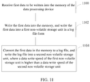
- FIG. 11 is a schematic flowchart of another data processing method according to an embodiment of the present invention, where the data processing method is applied in a data processing device and includes:
- the first data written into memory is written into the first non-volatile storage unit in the log file form, and the first data in the memory is converted to the log file and the converted log file is written into the second non-volatile storage unit. Because the data write speed of the first non-volatile storage unit is higher than the data write speed of the second non-volatile storage unit, fast backup of service data can be achieved, and especially for service data in the memory that needs to be stored by a storage processing device, the security of the memory data can be ensured.
- the first data is stored in the log file form, and the log file has metadata and can record only changed data and can implement data recovery; therefore when a capacity of the first non-volatile storage unit is smaller than a capacity of the memory, fast data backup can be achieved and data lost from the memory can be recovered when the data in the memory is lost.
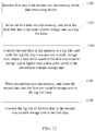
- FIG. 12 is a schematic flowchart of a further implementation of the method shown in FIG. 11 .
- the method further includes:
- the log file of the first data in the second non-volatile storage unit is converted to the first data, so that the first data in the memory can be recovered by using the first data in the second non-volatile storage unit when the first data in the memory is lost.
- the first data in the memory may further be written into the second non-volatile storage unit.
- a step of converting the log file of the first data in the second non-volatile storage unit to the first data is omitted, thereby further improving data storage efficiency.
- the first data lost from the memory can be recovered by using the first data in the second non-volatile storage unit.
- the log file of the first data in the second non-volatile storage unit can also be used to recover the first data lost from the memory. If a loss of the first data in the memory occurs during a process of converting the log file of the first data in the second non-volatile storage unit, the method may further include: determining whether a conversion from the log file of the first data to the first data is completed; when the conversion is not completed, recovering the first data in the memory by using converted first data and the log file of the first data that is not converted; and when the conversion is completed, recovering the first data in the memory by using converted first data.
- the second data lost from the memory is recovered by using a log file of the second data in the first non-volatile storage unit.
- Fast data read/write of the memory is achieved by using the foregoing manner of recovering the data lost from the memory.
- the lost data can be recovered in a timely manner, thereby ensuring service data security.
- FIG. 13 is a schematic flowchart of another data processing method according to an embodiment of the present invention, where the data processing method is applied in a data processing device and includes:
- the first data written into memory is written into the first non-volatile storage unit in the log file form, and the first data in the memory is written into the second non-volatile storage unit. Because the data write speed of the first non-volatile storage unit is higher than the data write speed of the second non-volatile storage unit, fast backup of service data can be achieved, and especially for service data in the memory that needs to be stored by a storage processing device, the security of the memory data can be ensured.
- the first data is stored in the log file form, and the log file has metadata and can record only changed data and can implement data recovery; therefore when a capacity of the first non-volatile storage unit is smaller than a capacity of the memory, fast data backup can be achieved and data lost from the memory can be recovered when the data in the memory is lost.
- the method further includes: writing second data into the memory, and writing the second data into the first non-volatile storage unit in the log file form.
- the first data in the memory is lost, the first data is recovered by using the first data in the second non-volatile storage unit.
- the data write speed of the first non-volatile storage unit is the same as a data write speed of the memory.
- Fast data read/write of the memory is achieved by using the foregoing manner of recovering the data lost from the memory.
- the lost data can be recovered in a timely manner, thereby ensuring service data security.
- the data processing device may be a server, including a hardware device, such as a CPU, a memory, a system bus, a power supply, and software run in the hardware, such as an operating system.
- the operating system is described by using a Linux operating system as an example.
- a block device subsystem in the Linux operating system of the server is connected to the memory of the server, and reads service data from the memory, or writes the service data into the memory.
- FIG. 5 is a schematic structural diagram of a specific application of a data processing device in a server according to an embodiment of the present invention.
- a memory read/write control unit 105 in FIG. 5 is connected to the block device subsystem to perform service data read/write control, and store, in a memory 101, all service data that needs to be stored, where the memory 101 may be a DRAM. Meanwhile, the memory read/write control unit 105 stores, in a log area of a first non-volatile storage unit 103 in a log file form, the data that needs to be written into the memory 101.
- a persistency control unit 106 reads the service data from the memory 101 and stores the service data in a log area of a second non-volatile storage unit 104, where the log area of the second non-volatile storage unit 104 stores the service data in the log file form, and a data area stores an original format of the service data. Meanwhile, a data scrubbing unit 107 further scrubs, to the data area, the data in the log area of the second non-volatile storage unit 104 or the data in the log area of the first non-volatile storage unit 103, and deletes the log file in the corresponding log area to release space occupied by the log file.
- a data recovery unit 108 reads the data in the data area of the persistency storage unit and recovers the data to the memory 101, or recovers the data lost from the memory 101 by using the log file in the first non-volatile storage unit 103 or the second non-volatile storage unit 104.
- Table 1 describes model selection examples of high-speed storage mediums, namely, the first non-volatile storage unit 103 and the second non-volatile storage unit 104 (only a part of combinations are listed).
- Table 1 Model Selection of the First Non-volatile Storage Unit 103 Model Selection of the Second Non-volatile Storage Unit 104
- Combination 1 NVDIMM (Non-Volatile Dual In-line Memory Module, non-volatile dual in-line memory module) and NVRAM (Non-Volatile Random Access Memory, non-volatile random access memory) SSD (Solid State Disk, solid state disk) and HD (Hard Disk, hard disk) Combination 2 SSD HD Combination 3 (low-cost combination) High-speed HD Low-speed HD Combination 4 NVDIMM, NVRAM Remote storage Combination 5 Remote NVDIMM and NVRAM Remote storage
- FIG. 6 is a schematic flowchart of a data read/write process performed by the memory read/write control unit 105 and the memory 101 in FIG. 5 , including:
- the memory 101 includes all service data that needs to be read, and compared with cache management such as a traditional cache query, in the manner of acquiring the memory offset in step A12, a time overhead and a space overhead are very small, the foregoing service data read process improves the service data read efficiency.
- a specific process of data reading A2 in FIG. 5 is as follows:
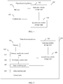
- FIG. 7 is a schematic diagram of a specific implementation manner of writing the service data into the memory 101 and the first non-volatile storage unit 103.
- FIG. 7 is a schematic diagram of a specific implementation manner of writing the service data into the memory 101 and the first non-volatile storage unit 103.
- step A22 may use the random writing manner; when the data is written into the first non-volatile storage unit 103, the continuous writing manner is used, that is, the log file "9a2b8c3d2elf" is written into the log area of the first non-volatile storage unit 103 in step A25.
- a completely continuous writing manner can improve the efficiency of writing the log file of the service data into the first non-persistency storage unit 103.
- the completely continuous writing manner indicates that the data is continuously written into the first non-persistency storage unit 103 and the data in the first non-persistency storage unit 103 is not read during the data writing process.
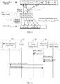
- FIG. 8-a is a schematic flowchart of acquiring a log file of first data from a first non-volatile storage unit and performing data persistency in FIG. 5 ; as shown in FIG. 8-a , a process of acquiring the log file from the first non-volatile storage unit 103 by the second non-volatile storage unit 104 is as follows:
- FIG. 8-b is a schematic flowchart of acquiring first data from a memory and performing data persistency in FIG. 5 ; as shown in FIG. 8-b , a process of acquiring the log file from the memory 101 by the second non-volatile storage unit 104 is as follows:
- step B13 the persistency control unit 106 directly reads the service data from the memory 101 without reading the service data from the first non-volatile storage unit 103, thereby achieving separation of reading and writing, easing pressure of the first non-volatile storage unit 103, and improving the efficiency of storing the service data in the memory by the first non-volatile storage unit 103.
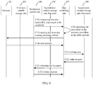
- FIG. 9 is a schematic flowchart of writing the service data in the memory 101 into the data area of the second non-volatile storage unit 104 by the data scrubbing unit 107 in FIG. 5 , including:
- step C13 the data scrubbing unit 107 directly reads the service data from the memory 101, thereby easing pressure of the second non-volatile storage unit 104, achieving separation of reading and writing, and improving the efficiency of writing the log file by the second non-volatile storage unit 104.
- the foregoing step C21 may also store, to the data space of the second non-volatile storage unit 104 from the log space of the second non-volatile storage unit 104, the service data to be scrubbed; accordingly, the data scrubbing unit 107 instructs the persistency control unit 106 to delete the log file, in the log area, of the service data that has been written into the second non-volatile storage unit 104, to release the log space occupied by the service data in the second non-volatile storage unit 104.
- the service data written into the memory 101 is stored in the log area of the first non-volatile storage unit 103 and the log area of the second non-volatile storage unit 104 in the log file form, so that the data lost from the memory 101 can be recovered by using these log files when the service data in the memory 101 (DRAM) is lost due to a restart caused by a failure, for example, the data processing device 100 is powered off.
- DRAM service data in the memory 101
- the data scrubbing unit 107 may convert the log file that has not been written into the log area of the second non-volatile storage unit 104 to the service data first and stores the service data in the data area; if the service data that has not been written into the log area of the second non-volatile storage unit 104 also exists before the data processing device 100 is restarted, because a data storage speed of the first non-volatile storage unit 103 is higher than a data storage speed of the second non-volatile storage unit 104, the data scrubbing unit 107 acquires the log file from the log area of the first non-volatile storage unit 103, converts the log file to the service data, and writes the converted service data into the data area of the second non-volatile storage unit 104.
- FIG. 10 is a schematic flowchart of a data recovery process performed by the data recovery unit 108 in FIG. 5 .
- the data recovery unit 108 invokes a sub-data scrubbing unit 107 to perform data scrubbing (step D111 and step D112), to scrub the data that has not been scrubbed before an abnormal power failure or normal powering off.
- a data recovery process is as follows:
- the read and write manners in the foregoing sequence can reach a maximum bandwidth throughput and further improve data read and write speed and efficiency.
- step D111 and step D 221 may be performed at the same time. If the data in the memory 101 is lost during a data scrubbing process, the data lost from the memory 101 is recovered by using the log files of the data that has been scrubbed and has not been scrubbed. If the data in the memory 101 is lost after the data in the memory 101 is written into the first non-volatile storage unit 103 but before the log file is written into the second non-volatile storage unit 104, the data lost from the memory 101 is recovered by using the log file in the first non-volatile storage unit 103.
- the implementation manner shown in FIG. 5 is a technical solution implemented on the server side.
- the data processing device and method in the embodiments of the present invention may further be implemented on a storage side and in a hardware card.
- Implementing the foregoing data processing device and method on the storage side can achieve a fact that all service data that needs to be stored is stored in the memory shared by remote ends.
- the hardware card that provides a function of the data processing device in the embodiment of the present invention and can implement the data processing method in the embodiment of the present invention can be connected to a server for implementation.
- the disclosed system, apparatus, and method may be implemented in other manners.
- the described apparatus embodiment is merely exemplary.
- the unit division is merely logical function division and may be other division in actual implementation.
- a plurality of units or components may be combined or integrated into another system, or some features may be ignored or not performed.
- the displayed or discussed mutual couplings or direct couplings or communication connections may be implemented through some interfaces.
- the indirect couplings or communication connections between the apparatuses or units may be implemented in electronic, mechanical, or other forms.
- the units described as separate parts may or may not be physically separate, and parts displayed as units may or may not be physical units, that is, may be located in one position, or may be distributed on a plurality of network units. A part or all of the units may be selected according to actual needs to achieve the objectives of the solutions of the embodiments of the present invention.
- functional units in the embodiments of the present invention may be integrated into one processing unit, or each of the units may exist alone physically, or two or more units are integrated into one unit.
- the integrated unit may be implemented in a form of hardware, or may be implemented in a form of a software functional unit.
- the integrated unit When the integrated unit is implemented in the form of a software functional unit and sold or used as an independent product, the integrated unit may be stored in a computer-readable storage medium. Based on such an understanding, the technical solutions of the present invention essentially, or the part contributing to the prior art, or all or a part of the technical solutions may be implemented in the form of a software product.
- the software product is stored in a storage medium and includes several instructions for instructing a computer device (which may be a personal computer, a server, or a network device, or the like) to perform all or a part of the steps of the methods described in the embodiments of the present invention.
- the foregoing storage medium includes: any medium that can store program code, such as a USB flash drive, a removable hard disk, a read-only memory (ROM, Read-Only Memory), a random access memory (RAM, Random Access Memory), a magnetic disk, or an optical disc.
- program code such as a USB flash drive, a removable hard disk, a read-only memory (ROM, Read-Only Memory), a random access memory (RAM, Random Access Memory), a magnetic disk, or an optical disc.
Landscapes
- Engineering & Computer Science (AREA)
- Theoretical Computer Science (AREA)
- Physics & Mathematics (AREA)
- General Engineering & Computer Science (AREA)
- General Physics & Mathematics (AREA)
- Human Computer Interaction (AREA)
- Quality & Reliability (AREA)
- Computer Security & Cryptography (AREA)
- Techniques For Improving Reliability Of Storages (AREA)
Priority Applications (1)
| Application Number | Priority Date | Filing Date | Title |
|---|---|---|---|
| EP17151712.1A EP3229140B1 (de) | 2013-12-02 | 2013-12-02 | Datenverarbeitungsvorrichtung und datenverarbeitungsverfahren |
Applications Claiming Priority (3)
| Application Number | Priority Date | Filing Date | Title |
|---|---|---|---|
| EP17151712.1A EP3229140B1 (de) | 2013-12-02 | 2013-12-02 | Datenverarbeitungsvorrichtung und datenverarbeitungsverfahren |
| EP13878532.4A EP2905706B1 (de) | 2013-12-02 | 2013-12-02 | Datenverarbeitungsvorrichtung und datenverarbeitungsverfahren |
| PCT/CN2013/088324 WO2015081470A1 (zh) | 2013-12-02 | 2013-12-02 | 数据处理设备和数据处理的方法 |
Related Parent Applications (2)
| Application Number | Title | Priority Date | Filing Date |
|---|---|---|---|
| EP13878532.4A Division EP2905706B1 (de) | 2013-12-02 | 2013-12-02 | Datenverarbeitungsvorrichtung und datenverarbeitungsverfahren |
| EP13878532.4A Division-Into EP2905706B1 (de) | 2013-12-02 | 2013-12-02 | Datenverarbeitungsvorrichtung und datenverarbeitungsverfahren |
Publications (2)
| Publication Number | Publication Date |
|---|---|
| EP3229140A1 true EP3229140A1 (de) | 2017-10-11 |
| EP3229140B1 EP3229140B1 (de) | 2019-02-20 |
Family
ID=53265424
Family Applications (2)
| Application Number | Title | Priority Date | Filing Date |
|---|---|---|---|
| EP17151712.1A Active EP3229140B1 (de) | 2013-12-02 | 2013-12-02 | Datenverarbeitungsvorrichtung und datenverarbeitungsverfahren |
| EP13878532.4A Active EP2905706B1 (de) | 2013-12-02 | 2013-12-02 | Datenverarbeitungsvorrichtung und datenverarbeitungsverfahren |
Family Applications After (1)
| Application Number | Title | Priority Date | Filing Date |
|---|---|---|---|
| EP13878532.4A Active EP2905706B1 (de) | 2013-12-02 | 2013-12-02 | Datenverarbeitungsvorrichtung und datenverarbeitungsverfahren |
Country Status (7)
| Country | Link |
|---|---|
| US (3) | US9354985B2 (de) |
| EP (2) | EP3229140B1 (de) |
| JP (1) | JP6166796B2 (de) |
| CN (2) | CN107357680A (de) |
| CA (1) | CA2896809C (de) |
| ES (1) | ES2627084T3 (de) |
| WO (1) | WO2015081470A1 (de) |
Families Citing this family (20)
| Publication number | Priority date | Publication date | Assignee | Title |
|---|---|---|---|---|
| US11829333B2 (en) * | 2015-05-08 | 2023-11-28 | Chicago Mercantile Exchange Inc. | Thread safe lock-free concurrent write operations for use with multi-threaded in-line logging |
| CN106469123A (zh) * | 2015-08-10 | 2017-03-01 | 北京忆恒创源科技有限公司 | 一种基于nvdimm的写缓存分配、释放方法及其装置 |
| CN111007991B (zh) * | 2015-08-13 | 2024-01-26 | 北京忆恒创源科技股份有限公司 | 基于nvdimm分离读写请求的方法及其计算机 |
| CN106919474A (zh) * | 2015-12-28 | 2017-07-04 | 中移(苏州)软件技术有限公司 | 一种缓存数据保护方法和装置 |
| US10210056B2 (en) * | 2016-03-31 | 2019-02-19 | Netapp, Inc. | Methods for filesystem metadata caching to improve failover performance and devices thereof |
| CN107562567A (zh) * | 2016-06-30 | 2018-01-09 | 华为技术有限公司 | 一种数据处理方法以及数据处理设备 |
| US11977484B2 (en) | 2016-07-19 | 2024-05-07 | Sap Se | Adapting in-memory database in hybrid memory systems and operating system interface |
| US10783146B2 (en) * | 2016-07-19 | 2020-09-22 | Sap Se | Join operations in hybrid main memory systems |
| US10698732B2 (en) | 2016-07-19 | 2020-06-30 | Sap Se | Page ranking in operating system virtual pages in hybrid memory systems |
| WO2018233820A1 (en) * | 2017-06-21 | 2018-12-27 | Huawei Technologies Co., Ltd. | Systems and methods for management of a log-structure |
| US11010379B2 (en) | 2017-08-15 | 2021-05-18 | Sap Se | Increasing performance of in-memory databases using re-ordered query execution plans |
| CN109992448B (zh) * | 2017-12-31 | 2021-08-06 | 中国移动通信集团山西有限公司 | 文件变化增量备份方法、装置、设备及介质 |
| CN108494481B (zh) * | 2018-03-30 | 2020-06-09 | 青岛海信宽带多媒体技术有限公司 | 光模块的监控数据处理方法、装置及光模块 |
| CN108521551A (zh) * | 2018-05-14 | 2018-09-11 | 河北远东通信系统工程有限公司 | 一种网络实时视频录制存储方法和系统以及文件恢复方法 |
| CN108763572B (zh) * | 2018-06-06 | 2021-06-22 | 湖南蚁坊软件股份有限公司 | 一种实现Apache Solr读写分离的方法和装置 |
| CN109165117B (zh) * | 2018-06-29 | 2022-05-31 | 华为技术有限公司 | 数据处理的方法和系统 |
| WO2021226822A1 (zh) * | 2020-05-12 | 2021-11-18 | 深圳市欢太科技有限公司 | 日志写入方法、装置、电子设备以及存储介质 |
| US11947839B2 (en) | 2021-05-10 | 2024-04-02 | Samsung Electronics Co., Ltd. | Storage device, system, and method for customizable metadata |
| CN113722158B (zh) * | 2021-10-08 | 2022-08-30 | 亿次网联(杭州)科技有限公司 | 电子设备及其掉电保护方法、装置、存储介质 |
| CN114780356B (zh) * | 2022-06-22 | 2022-09-23 | 北京得瑞领新科技有限公司 | Ssd系统日志数据的存储方法及装置、介质、设备 |
Citations (5)
| Publication number | Priority date | Publication date | Assignee | Title |
|---|---|---|---|---|
| EP0618533A2 (de) * | 1993-03-30 | 1994-10-05 | Fujitsu Limited | Verfahren und Anordnung zur Klassifizierung und Erfassungslogdaten |
| EP0790558A1 (de) * | 1996-02-06 | 1997-08-20 | Telefonaktiebolaget Lm Ericsson | Verfahren und System zur schnellen Wiederherstellung einer Primärspeicherdatenbank |
| CN1783025A (zh) * | 2004-12-03 | 2006-06-07 | 华为技术有限公司 | 嵌入式系统数据备份装置及方法 |
| US20090216943A1 (en) * | 2008-02-21 | 2009-08-27 | Hitachi Global Storage Technologies Netherlands B. V. | Data storage device and data management method in data storage device |
| US8041679B1 (en) * | 2008-06-04 | 2011-10-18 | Symantec Operating Corporation | Synthetic differential backups creation for a database using binary log conversion |
Family Cites Families (25)
| Publication number | Priority date | Publication date | Assignee | Title |
|---|---|---|---|---|
| KR900019014A (ko) * | 1988-05-25 | 1990-12-22 | 아오이 죠이치 | 반도체메모리의 데이터기록방법 및 그 장치 |
| JP3594248B2 (ja) * | 1993-03-30 | 2004-11-24 | 富士通株式会社 | ログデータの分類取得システム |
| JP2003131955A (ja) * | 2001-10-19 | 2003-05-09 | Kyocera Corp | データバックアップ回路 |
| US7596672B1 (en) | 2003-10-24 | 2009-09-29 | Network Appliance, Inc. | Synchronous mirroring including writing image updates to a file |
| US7203796B1 (en) * | 2003-10-24 | 2007-04-10 | Network Appliance, Inc. | Method and apparatus for synchronous data mirroring |
| US7197520B1 (en) * | 2004-04-14 | 2007-03-27 | Veritas Operating Corporation | Two-tier backup mechanism |
| CN100399288C (zh) * | 2005-09-30 | 2008-07-02 | 联想(北京)有限公司 | 一种内存备份装置和方法 |
| JP5009700B2 (ja) * | 2007-06-26 | 2012-08-22 | 株式会社リコー | データ記憶装置、プログラムおよびデータ記憶方法 |
| CN101216772B (zh) * | 2008-01-15 | 2011-05-11 | 中兴通讯股份有限公司 | 一种嵌入式设备的启动方法及软件升级方法 |
| CN101620460A (zh) * | 2008-07-02 | 2010-01-06 | 联想(北京)有限公司 | 一种计算机系统休眠方法和一种计算机系统 |
| JP2010152514A (ja) * | 2008-12-24 | 2010-07-08 | Toshiba Corp | メモリシステム |
| KR20100133710A (ko) * | 2009-06-12 | 2010-12-22 | 삼성전자주식회사 | 메모리 시스템 및 그것의 코드 데이터 로딩 방법 |
| CN101996677B (zh) * | 2009-08-26 | 2013-12-11 | 联华电子股份有限公司 | 非易失性静态随机存取存储器元件 |
| WO2011070611A1 (en) * | 2009-12-08 | 2011-06-16 | Hitachi, Ltd. | Storage system and storage control apparatus provided with cache memory group including volatile memory and nonvolatile memory |
| US8572311B1 (en) * | 2010-01-11 | 2013-10-29 | Apple Inc. | Redundant data storage in multi-die memory systems |
| CN102014152A (zh) * | 2010-10-18 | 2011-04-13 | 浪潮(北京)电子信息产业有限公司 | 一种远程复制系统及其方法 |
| US10817502B2 (en) * | 2010-12-13 | 2020-10-27 | Sandisk Technologies Llc | Persistent memory management |
| US20140081911A1 (en) * | 2011-01-10 | 2014-03-20 | Netapp, Inc. | Optimizing automatic deletion of backup files |
| CN102693170A (zh) * | 2011-03-21 | 2012-09-26 | 北京千橡网景科技发展有限公司 | 用于内存管理的方法和设备 |
| CN102467404A (zh) * | 2011-10-14 | 2012-05-23 | 海尔集团技术研发中心 | 一种基于物理内存实现软件快速切换的方法及装置 |
| CN102779072B (zh) * | 2012-06-18 | 2014-06-25 | 中国科学院上海微系统与信息技术研究所 | 一种嵌入式系统及其应用进程的休眠与唤醒方法 |
| JP5631938B2 (ja) * | 2012-07-19 | 2014-11-26 | 株式会社東芝 | 半導体記憶装置 |
| GB2508659A (en) * | 2012-12-10 | 2014-06-11 | Ibm | Backing up an in-memory database |
| US11687292B2 (en) * | 2013-02-26 | 2023-06-27 | Seagate Technology Llc | Data update management in a cloud computing environment |
| US9164856B2 (en) * | 2013-11-11 | 2015-10-20 | International Business Machines Corporation | Persistent messaging mechanism |
-
2013
- 2013-12-02 CA CA2896809A patent/CA2896809C/en active Active
- 2013-12-02 JP JP2015556373A patent/JP6166796B2/ja active Active
- 2013-12-02 ES ES13878532.4T patent/ES2627084T3/es active Active
- 2013-12-02 CN CN201710448821.5A patent/CN107357680A/zh active Pending
- 2013-12-02 EP EP17151712.1A patent/EP3229140B1/de active Active
- 2013-12-02 EP EP13878532.4A patent/EP2905706B1/de active Active
- 2013-12-02 CN CN201380002636.3A patent/CN104919426A/zh active Pending
- 2013-12-02 WO PCT/CN2013/088324 patent/WO2015081470A1/zh not_active Ceased
-
2014
- 2014-09-11 US US14/483,970 patent/US9354985B2/en active Active
-
2015
- 2015-05-05 US US14/704,720 patent/US9557927B2/en active Active
-
2016
- 2016-12-20 US US15/385,661 patent/US20170103001A1/en not_active Abandoned
Patent Citations (5)
| Publication number | Priority date | Publication date | Assignee | Title |
|---|---|---|---|---|
| EP0618533A2 (de) * | 1993-03-30 | 1994-10-05 | Fujitsu Limited | Verfahren und Anordnung zur Klassifizierung und Erfassungslogdaten |
| EP0790558A1 (de) * | 1996-02-06 | 1997-08-20 | Telefonaktiebolaget Lm Ericsson | Verfahren und System zur schnellen Wiederherstellung einer Primärspeicherdatenbank |
| CN1783025A (zh) * | 2004-12-03 | 2006-06-07 | 华为技术有限公司 | 嵌入式系统数据备份装置及方法 |
| US20090216943A1 (en) * | 2008-02-21 | 2009-08-27 | Hitachi Global Storage Technologies Netherlands B. V. | Data storage device and data management method in data storage device |
| US8041679B1 (en) * | 2008-06-04 | 2011-10-18 | Symantec Operating Corporation | Synthetic differential backups creation for a database using binary log conversion |
Also Published As
| Publication number | Publication date |
|---|---|
| CA2896809C (en) | 2020-06-02 |
| EP2905706A4 (de) | 2016-05-04 |
| ES2627084T3 (es) | 2017-07-26 |
| US20170103001A1 (en) | 2017-04-13 |
| US20150234615A1 (en) | 2015-08-20 |
| CN107357680A (zh) | 2017-11-17 |
| WO2015081470A1 (zh) | 2015-06-11 |
| JP2016509734A (ja) | 2016-03-31 |
| JP6166796B2 (ja) | 2017-07-19 |
| EP3229140B1 (de) | 2019-02-20 |
| CA2896809A1 (en) | 2015-06-11 |
| US9557927B2 (en) | 2017-01-31 |
| EP2905706A1 (de) | 2015-08-12 |
| US9354985B2 (en) | 2016-05-31 |
| CN104919426A (zh) | 2015-09-16 |
| EP2905706B1 (de) | 2017-04-05 |
| US20150154087A1 (en) | 2015-06-04 |
Similar Documents
| Publication | Publication Date | Title |
|---|---|---|
| CA2896809C (en) | Data processing device and data processing method | |
| US9823877B2 (en) | Virtual machine backup from storage snapshot | |
| US11397648B2 (en) | Virtual machine recovery method and virtual machine management device | |
| US10102076B2 (en) | System and method for implementing a block-based backup restart | |
| US20100058007A1 (en) | Information processing apparatus and memory management method | |
| CN115543696B (zh) | 一种磁盘阵列重构任务加速方法、系统、存储介质及设备 | |
| US10853199B2 (en) | Techniques for managing context information for a storage device while maintaining responsiveness | |
| CN104571955A (zh) | 提高存储容量的方法和装置 | |
| WO2016095372A1 (zh) | 实现事务日志镜像备份的方法及装置 | |
| WO2020034695A1 (zh) | 数据存储方法、数据恢复方法、装置、设备及存储介质 | |
| US20220019506A1 (en) | High Availability For Persistent Memory | |
| US12265451B2 (en) | Data processing method and apparatus in storage system, and storage system | |
| KR102277731B1 (ko) | 스토리지 시스템의 구동 방법 및 스토리지 컨트롤러 | |
| US11487428B2 (en) | Storage control apparatus and storage control method | |
| CN103049407A (zh) | 数据存储方法、装置及系统 | |
| CN110018986B (zh) | 异常快照识别方法及装置 | |
| US20130332658A1 (en) | Data storage system and method thereof | |
| KR20140040018A (ko) | 하이버네이션 기반 스냅샷 이미지 생성 및 부팅 장치 및 방법 |
Legal Events
| Date | Code | Title | Description |
|---|---|---|---|
| PUAI | Public reference made under article 153(3) epc to a published international application that has entered the european phase |
Free format text: ORIGINAL CODE: 0009012 |
|
| STAA | Information on the status of an ep patent application or granted ep patent |
Free format text: STATUS: THE APPLICATION HAS BEEN PUBLISHED |
|
| AC | Divisional application: reference to earlier application |
Ref document number: 2905706 Country of ref document: EP Kind code of ref document: P |
|
| AK | Designated contracting states |
Kind code of ref document: A1 Designated state(s): AL AT BE BG CH CY CZ DE DK EE ES FI FR GB GR HR HU IE IS IT LI LT LU LV MC MK MT NL NO PL PT RO RS SE SI SK SM TR |
|
| STAA | Information on the status of an ep patent application or granted ep patent |
Free format text: STATUS: REQUEST FOR EXAMINATION WAS MADE |
|
| 17P | Request for examination filed |
Effective date: 20171011 |
|
| RBV | Designated contracting states (corrected) |
Designated state(s): AL AT BE BG CH CY CZ DE DK EE ES FI FR GB GR HR HU IE IS IT LI LT LU LV MC MK MT NL NO PL PT RO RS SE SI SK SM TR |
|
| GRAP | Despatch of communication of intention to grant a patent |
Free format text: ORIGINAL CODE: EPIDOSNIGR1 |
|
| STAA | Information on the status of an ep patent application or granted ep patent |
Free format text: STATUS: GRANT OF PATENT IS INTENDED |
|
| INTG | Intention to grant announced |
Effective date: 20180705 |
|
| GRAS | Grant fee paid |
Free format text: ORIGINAL CODE: EPIDOSNIGR3 |
|
| GRAA | (expected) grant |
Free format text: ORIGINAL CODE: 0009210 |
|
| STAA | Information on the status of an ep patent application or granted ep patent |
Free format text: STATUS: THE PATENT HAS BEEN GRANTED |
|
| AC | Divisional application: reference to earlier application |
Ref document number: 2905706 Country of ref document: EP Kind code of ref document: P |
|
| AK | Designated contracting states |
Kind code of ref document: B1 Designated state(s): AL AT BE BG CH CY CZ DE DK EE ES FI FR GB GR HR HU IE IS IT LI LT LU LV MC MK MT NL NO PL PT RO RS SE SI SK SM TR |
|
| REG | Reference to a national code |
Ref country code: GB Ref legal event code: FG4D |
|
| REG | Reference to a national code |
Ref country code: CH Ref legal event code: EP |
|
| REG | Reference to a national code |
Ref country code: DE Ref legal event code: R096 Ref document number: 602013051269 Country of ref document: DE |
|
| REG | Reference to a national code |
Ref country code: AT Ref legal event code: REF Ref document number: 1099102 Country of ref document: AT Kind code of ref document: T Effective date: 20190315 |
|
| REG | Reference to a national code |
Ref country code: IE Ref legal event code: FG4D |
|
| REG | Reference to a national code |
Ref country code: LT Ref legal event code: MG4D Ref country code: NL Ref legal event code: MP Effective date: 20190220 |
|
| PG25 | Lapsed in a contracting state [announced via postgrant information from national office to epo] |
Ref country code: LT Free format text: LAPSE BECAUSE OF FAILURE TO SUBMIT A TRANSLATION OF THE DESCRIPTION OR TO PAY THE FEE WITHIN THE PRESCRIBED TIME-LIMIT Effective date: 20190220 Ref country code: ES Free format text: LAPSE BECAUSE OF FAILURE TO SUBMIT A TRANSLATION OF THE DESCRIPTION OR TO PAY THE FEE WITHIN THE PRESCRIBED TIME-LIMIT Effective date: 20190220 Ref country code: FI Free format text: LAPSE BECAUSE OF FAILURE TO SUBMIT A TRANSLATION OF THE DESCRIPTION OR TO PAY THE FEE WITHIN THE PRESCRIBED TIME-LIMIT Effective date: 20190220 Ref country code: NO Free format text: LAPSE BECAUSE OF FAILURE TO SUBMIT A TRANSLATION OF THE DESCRIPTION OR TO PAY THE FEE WITHIN THE PRESCRIBED TIME-LIMIT Effective date: 20190520 Ref country code: PT Free format text: LAPSE BECAUSE OF FAILURE TO SUBMIT A TRANSLATION OF THE DESCRIPTION OR TO PAY THE FEE WITHIN THE PRESCRIBED TIME-LIMIT Effective date: 20190620 Ref country code: SE Free format text: LAPSE BECAUSE OF FAILURE TO SUBMIT A TRANSLATION OF THE DESCRIPTION OR TO PAY THE FEE WITHIN THE PRESCRIBED TIME-LIMIT Effective date: 20190220 |
|
| PG25 | Lapsed in a contracting state [announced via postgrant information from national office to epo] |
Ref country code: BG Free format text: LAPSE BECAUSE OF FAILURE TO SUBMIT A TRANSLATION OF THE DESCRIPTION OR TO PAY THE FEE WITHIN THE PRESCRIBED TIME-LIMIT Effective date: 20190520 Ref country code: GR Free format text: LAPSE BECAUSE OF FAILURE TO SUBMIT A TRANSLATION OF THE DESCRIPTION OR TO PAY THE FEE WITHIN THE PRESCRIBED TIME-LIMIT Effective date: 20190521 Ref country code: LV Free format text: LAPSE BECAUSE OF FAILURE TO SUBMIT A TRANSLATION OF THE DESCRIPTION OR TO PAY THE FEE WITHIN THE PRESCRIBED TIME-LIMIT Effective date: 20190220 Ref country code: IS Free format text: LAPSE BECAUSE OF FAILURE TO SUBMIT A TRANSLATION OF THE DESCRIPTION OR TO PAY THE FEE WITHIN THE PRESCRIBED TIME-LIMIT Effective date: 20190620 Ref country code: RS Free format text: LAPSE BECAUSE OF FAILURE TO SUBMIT A TRANSLATION OF THE DESCRIPTION OR TO PAY THE FEE WITHIN THE PRESCRIBED TIME-LIMIT Effective date: 20190220 Ref country code: HR Free format text: LAPSE BECAUSE OF FAILURE TO SUBMIT A TRANSLATION OF THE DESCRIPTION OR TO PAY THE FEE WITHIN THE PRESCRIBED TIME-LIMIT Effective date: 20190220 Ref country code: NL Free format text: LAPSE BECAUSE OF FAILURE TO SUBMIT A TRANSLATION OF THE DESCRIPTION OR TO PAY THE FEE WITHIN THE PRESCRIBED TIME-LIMIT Effective date: 20190220 |
|
| REG | Reference to a national code |
Ref country code: AT Ref legal event code: MK05 Ref document number: 1099102 Country of ref document: AT Kind code of ref document: T Effective date: 20190220 |
|
| PG25 | Lapsed in a contracting state [announced via postgrant information from national office to epo] |
Ref country code: CZ Free format text: LAPSE BECAUSE OF FAILURE TO SUBMIT A TRANSLATION OF THE DESCRIPTION OR TO PAY THE FEE WITHIN THE PRESCRIBED TIME-LIMIT Effective date: 20190220 Ref country code: AL Free format text: LAPSE BECAUSE OF FAILURE TO SUBMIT A TRANSLATION OF THE DESCRIPTION OR TO PAY THE FEE WITHIN THE PRESCRIBED TIME-LIMIT Effective date: 20190220 Ref country code: RO Free format text: LAPSE BECAUSE OF FAILURE TO SUBMIT A TRANSLATION OF THE DESCRIPTION OR TO PAY THE FEE WITHIN THE PRESCRIBED TIME-LIMIT Effective date: 20190220 Ref country code: EE Free format text: LAPSE BECAUSE OF FAILURE TO SUBMIT A TRANSLATION OF THE DESCRIPTION OR TO PAY THE FEE WITHIN THE PRESCRIBED TIME-LIMIT Effective date: 20190220 Ref country code: SK Free format text: LAPSE BECAUSE OF FAILURE TO SUBMIT A TRANSLATION OF THE DESCRIPTION OR TO PAY THE FEE WITHIN THE PRESCRIBED TIME-LIMIT Effective date: 20190220 Ref country code: IT Free format text: LAPSE BECAUSE OF FAILURE TO SUBMIT A TRANSLATION OF THE DESCRIPTION OR TO PAY THE FEE WITHIN THE PRESCRIBED TIME-LIMIT Effective date: 20190220 Ref country code: DK Free format text: LAPSE BECAUSE OF FAILURE TO SUBMIT A TRANSLATION OF THE DESCRIPTION OR TO PAY THE FEE WITHIN THE PRESCRIBED TIME-LIMIT Effective date: 20190220 |
|
| REG | Reference to a national code |
Ref country code: DE Ref legal event code: R097 Ref document number: 602013051269 Country of ref document: DE |
|
| PG25 | Lapsed in a contracting state [announced via postgrant information from national office to epo] |
Ref country code: PL Free format text: LAPSE BECAUSE OF FAILURE TO SUBMIT A TRANSLATION OF THE DESCRIPTION OR TO PAY THE FEE WITHIN THE PRESCRIBED TIME-LIMIT Effective date: 20190220 Ref country code: SM Free format text: LAPSE BECAUSE OF FAILURE TO SUBMIT A TRANSLATION OF THE DESCRIPTION OR TO PAY THE FEE WITHIN THE PRESCRIBED TIME-LIMIT Effective date: 20190220 |
|
| PLBE | No opposition filed within time limit |
Free format text: ORIGINAL CODE: 0009261 |
|
| STAA | Information on the status of an ep patent application or granted ep patent |
Free format text: STATUS: NO OPPOSITION FILED WITHIN TIME LIMIT |
|
| PG25 | Lapsed in a contracting state [announced via postgrant information from national office to epo] |
Ref country code: AT Free format text: LAPSE BECAUSE OF FAILURE TO SUBMIT A TRANSLATION OF THE DESCRIPTION OR TO PAY THE FEE WITHIN THE PRESCRIBED TIME-LIMIT Effective date: 20190220 |
|
| 26N | No opposition filed |
Effective date: 20191121 |
|
| PG25 | Lapsed in a contracting state [announced via postgrant information from national office to epo] |
Ref country code: SI Free format text: LAPSE BECAUSE OF FAILURE TO SUBMIT A TRANSLATION OF THE DESCRIPTION OR TO PAY THE FEE WITHIN THE PRESCRIBED TIME-LIMIT Effective date: 20190220 |
|
| PG25 | Lapsed in a contracting state [announced via postgrant information from national office to epo] |
Ref country code: TR Free format text: LAPSE BECAUSE OF FAILURE TO SUBMIT A TRANSLATION OF THE DESCRIPTION OR TO PAY THE FEE WITHIN THE PRESCRIBED TIME-LIMIT Effective date: 20190220 |
|
| REG | Reference to a national code |
Ref country code: CH Ref legal event code: PL |
|
| REG | Reference to a national code |
Ref country code: BE Ref legal event code: MM Effective date: 20191231 |
|
| PG25 | Lapsed in a contracting state [announced via postgrant information from national office to epo] |
Ref country code: MC Free format text: LAPSE BECAUSE OF FAILURE TO SUBMIT A TRANSLATION OF THE DESCRIPTION OR TO PAY THE FEE WITHIN THE PRESCRIBED TIME-LIMIT Effective date: 20190220 |
|
| PG25 | Lapsed in a contracting state [announced via postgrant information from national office to epo] |
Ref country code: LU Free format text: LAPSE BECAUSE OF NON-PAYMENT OF DUE FEES Effective date: 20191202 |
|
| PG25 | Lapsed in a contracting state [announced via postgrant information from national office to epo] |
Ref country code: CH Free format text: LAPSE BECAUSE OF NON-PAYMENT OF DUE FEES Effective date: 20191231 Ref country code: LI Free format text: LAPSE BECAUSE OF NON-PAYMENT OF DUE FEES Effective date: 20191231 Ref country code: BE Free format text: LAPSE BECAUSE OF NON-PAYMENT OF DUE FEES Effective date: 20191231 |
|
| PG25 | Lapsed in a contracting state [announced via postgrant information from national office to epo] |
Ref country code: CY Free format text: LAPSE BECAUSE OF FAILURE TO SUBMIT A TRANSLATION OF THE DESCRIPTION OR TO PAY THE FEE WITHIN THE PRESCRIBED TIME-LIMIT Effective date: 20190220 |
|
| PG25 | Lapsed in a contracting state [announced via postgrant information from national office to epo] |
Ref country code: MT Free format text: LAPSE BECAUSE OF FAILURE TO SUBMIT A TRANSLATION OF THE DESCRIPTION OR TO PAY THE FEE WITHIN THE PRESCRIBED TIME-LIMIT Effective date: 20190220 Ref country code: HU Free format text: LAPSE BECAUSE OF FAILURE TO SUBMIT A TRANSLATION OF THE DESCRIPTION OR TO PAY THE FEE WITHIN THE PRESCRIBED TIME-LIMIT; INVALID AB INITIO Effective date: 20131202 |
|
| REG | Reference to a national code |
Ref country code: DE Ref legal event code: R081 Ref document number: 602013051269 Country of ref document: DE Owner name: HUAWEI CLOUD COMPUTING TECHNOLOGIES CO., LTD.,, CN Free format text: FORMER OWNER: HUAWEI TECHNOLOGIES CO., LTD., SHENZHEN, GUANGDONG, CN |
|
| REG | Reference to a national code |
Ref country code: GB Ref legal event code: 732E Free format text: REGISTERED BETWEEN 20220428 AND 20220504 |
|
| PG25 | Lapsed in a contracting state [announced via postgrant information from national office to epo] |
Ref country code: MK Free format text: LAPSE BECAUSE OF FAILURE TO SUBMIT A TRANSLATION OF THE DESCRIPTION OR TO PAY THE FEE WITHIN THE PRESCRIBED TIME-LIMIT Effective date: 20190220 |
|
| P01 | Opt-out of the competence of the unified patent court (upc) registered |
Effective date: 20230524 |
|
| PGFP | Annual fee paid to national office [announced via postgrant information from national office to epo] |
Ref country code: DE Payment date: 20251104 Year of fee payment: 13 |
|
| PGFP | Annual fee paid to national office [announced via postgrant information from national office to epo] |
Ref country code: GB Payment date: 20251030 Year of fee payment: 13 |
|
| PGFP | Annual fee paid to national office [announced via postgrant information from national office to epo] |
Ref country code: FR Payment date: 20251110 Year of fee payment: 13 |
|
| PGFP | Annual fee paid to national office [announced via postgrant information from national office to epo] |
Ref country code: IE Payment date: 20251111 Year of fee payment: 13 |