EP3229459A1 - Informationsverarbeitungsvorrichtung, informationsverarbeitungsverfahren und programm - Google Patents
Informationsverarbeitungsvorrichtung, informationsverarbeitungsverfahren und programm Download PDFInfo
- Publication number
- EP3229459A1 EP3229459A1 EP15865510.0A EP15865510A EP3229459A1 EP 3229459 A1 EP3229459 A1 EP 3229459A1 EP 15865510 A EP15865510 A EP 15865510A EP 3229459 A1 EP3229459 A1 EP 3229459A1
- Authority
- EP
- European Patent Office
- Prior art keywords
- information processing
- visual target
- processing device
- space
- target positions
- Prior art date
- Legal status (The legal status is an assumption and is not a legal conclusion. Google has not performed a legal analysis and makes no representation as to the accuracy of the status listed.)
- Granted
Links
Images


Classifications
-
- G—PHYSICS
- G01—MEASURING; TESTING
- G01B—MEASURING LENGTH, THICKNESS OR SIMILAR LINEAR DIMENSIONS; MEASURING ANGLES; MEASURING AREAS; MEASURING IRREGULARITIES OF SURFACES OR CONTOURS
- G01B11/00—Measuring arrangements characterised by the use of optical techniques
- G01B11/02—Measuring arrangements characterised by the use of optical techniques for measuring length, width or thickness
- G01B11/03—Measuring arrangements characterised by the use of optical techniques for measuring length, width or thickness by measuring coordinates of points
-
- G—PHYSICS
- G01—MEASURING; TESTING
- G01B—MEASURING LENGTH, THICKNESS OR SIMILAR LINEAR DIMENSIONS; MEASURING ANGLES; MEASURING AREAS; MEASURING IRREGULARITIES OF SURFACES OR CONTOURS
- G01B11/00—Measuring arrangements characterised by the use of optical techniques
-
- G—PHYSICS
- G06—COMPUTING OR CALCULATING; COUNTING
- G06T—IMAGE DATA PROCESSING OR GENERATION, IN GENERAL
- G06T11/00—Two-dimensional [2D] image generation
- G06T11/60—Creating or editing images; Combining images with text
-
- H—ELECTRICITY
- H04—ELECTRIC COMMUNICATION TECHNIQUE
- H04N—PICTORIAL COMMUNICATION, e.g. TELEVISION
- H04N23/00—Cameras or camera modules comprising electronic image sensors; Control thereof
- H04N23/60—Control of cameras or camera modules
- H04N23/61—Control of cameras or camera modules based on recognised objects
-
- H—ELECTRICITY
- H04—ELECTRIC COMMUNICATION TECHNIQUE
- H04N—PICTORIAL COMMUNICATION, e.g. TELEVISION
- H04N23/00—Cameras or camera modules comprising electronic image sensors; Control thereof
- H04N23/60—Control of cameras or camera modules
- H04N23/61—Control of cameras or camera modules based on recognised objects
- H04N23/611—Control of cameras or camera modules based on recognised objects where the recognised objects include parts of the human body
-
- H—ELECTRICITY
- H04—ELECTRIC COMMUNICATION TECHNIQUE
- H04N—PICTORIAL COMMUNICATION, e.g. TELEVISION
- H04N23/00—Cameras or camera modules comprising electronic image sensors; Control thereof
- H04N23/60—Control of cameras or camera modules
- H04N23/66—Remote control of cameras or camera parts, e.g. by remote control devices
- H04N23/661—Transmitting camera control signals through networks, e.g. control via the Internet
-
- H—ELECTRICITY
- H04—ELECTRIC COMMUNICATION TECHNIQUE
- H04N—PICTORIAL COMMUNICATION, e.g. TELEVISION
- H04N23/00—Cameras or camera modules comprising electronic image sensors; Control thereof
- H04N23/90—Arrangement of cameras or camera modules, e.g. multiple cameras in TV studios or sports stadiums
Definitions
- the present disclosure relates to information processing devices, information processing methods, and programs.
- Patent Literature 1 is an example of such technologies.
- the present disclosure proposes a novel and improved information processing device, information processing method, and program that are capable of appropriately deciding an image generation target position in a space.
- an information processing device including a processor configured to achieve a function of collecting information indicating visual target positions from a plurality of viewpoints existing in a space, and a function of evaluating positions in the space in accordance with density of the visual target positions.
- an information processing method including collecting information indicating visual target positions from a plurality of viewpoints existing in a space, and evaluating, by a processor, positions in the space in accordance with density of the visual target positions.
- a program causing a processor to achieve: a function of collecting information indicating visual target positions from a plurality of viewpoints existing in a space; and a function of evaluating positions in the space in accordance with density of the visual target positions.
- spatial ratings are estimated on the basis of density of visual target positions from a plurality of viewpoints existing in a space.
- the spatial ratings represent how much attention each position in a space is attracting.
- the plurality of viewpoint may include viewpoints of an audience in the sports stadium.
- the plurality of viewpoints may include viewpoints of cameras installed in the sports stadium.
- visual target positions from such viewpoints are gaze positions.
- a position on which gazes of the audience and the cameras are concentrated, that is, the position with high spatial ratings may be estimated to be attracting much attention in the sports stadium.
- three-dimensional point cloud data is generated on the basis of such spatial ratings so as to provide a free-viewpoint image.
- the images include moving images (video) and still images.
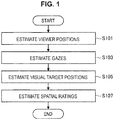
- FIG. 1 is a flowchart schematically illustrating a process of spatial rating estimation according to an embodiment of the present disclosure.
- viewer positions are estimated (S101) according to the embodiment.
- the term "viewer” means a subject whose viewpoint is in a space, such as the audience or the camera.
- the viewer positions are estimated by performing self-location estimation on the basis of viewpoint images provided by the viewers, for example. Technologies such as simultaneous localization and mapping (SLAM) may be used for the self-location estimation based on images.
- SLAM simultaneous localization and mapping
- information of a landmark in the space, information of a three-dimensional model of the space, or the like may be used.
- the viewer positions may be estimated on the basis of information provided by the viewers themselves. In this case, for example, positioning using radio waves from a base station such as Global Navigation Satellite System (GNSS) or Wi-Fi, or position indication that is specific for a space (for example, location of audience seat in sports stadium indicated by ticket information) may be used.
- GNSS Global Navigation Satellite
- a central direction of a viewpoint image provided by a viewer may be considered as a gaze direction.
- viewpoint estimation is possible in the case where the viewer is an audience wearing a wearable camera.
- an image of eyes captured with an inward-facing camera that is provided in addition to a viewpoint image captured by the audience with an outward-facing camera is used. More specifically, it is possible to estimate a gaze from central positions of pupils, and it is also possible to estimate a gaze from an attitude of an eyeball model.
- visual target positions of the viewers are estimated (S105) on the basis of the viewer positions estimated in S101 and the gazes estimated in S103.
- the visual target position is specified as a position on a gaze from the viewer position.
- a position at which the gaze intersects with a ground or a floor is estimated as the visual target position by using the three-dimensional model of the space.
- the process until estimating a visual target position in S105 may be performed in a client device corresponding to each viewer, or may be performed in a server that collects data such as images from the client devices, for example.
- spatial ratings are estimated on the basis of the visual target positions estimated in S105.
- the spatial ratings are estimated on the basis of density of the visual target positions in the space.
- a server configured to estimate spatial ratings have collected information indicating a visual target position of each user (in order words, visual target positions from a plurality of viewpoints existing in the space).
- the spatial ratings may be calculated for each grid obtained by dividing the space into a predetermined size, or may be calculated for each cluster including the visual target positions that are close to each other, for example.
- the spatial ratings estimated through the above described process are used for generating point cloud data for providing a free-viewpoint image. More specifically, for example, the point cloud data is generated with regard to a position whose spatial rating (density of visual target positions) exceeds a threshold.
- the data for providing a free-viewpoint image through such a method may be generated on the basis of spatial ratings.
- JP 2007-133660A describes a technology for providing a free-viewpoint image.
- the free-viewpoint image By using the free-viewpoint image, it is possible to observe any position in a space from any angle. However, for example, in the case where the free-viewpoint image is provided without pinpointing a position, a user who views a captured image ex-post facto cannot decide which position to look at. Therefore, the user does not always gain better experience. In addition, vast amounts of data are necessary when providing a free-viewpoint image by using all the available images. Therefore, according to the embodiment, a target position to which a free-viewpoint image is provided is limited on the basis of spatial ratings. Thereby, it is possible to provide a user-friendly free-viewpoint image and prevent data for providing the free-viewpoint image from becoming unnecessarily too much.
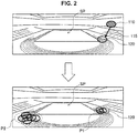
- FIG. 2 is a diagram schematically illustrating spatial rating estimation according to an embodiment of the present disclosure.
- a viewer position 110 in a space SP sports stadium in the illustrated example
- the viewer position 110 may be a position of a camera or an audience to whom a viewpoint image is provided.
- a gaze 115 is estimated.
- the gaze 115 may be considered as going along a central direction of a viewpoint image, or may be detected by using a gaze detection technology in the case where the viewer is an audience.
- a visual target position 120 in the space SP is estimated.
- the visual target position 120 may be estimated as a position at which the gaze 115 intersects with a ground (or floor).
- the spatial ratings are estimated in accordance with density of the visual target positions 120. In the illustrated example, relatively high spatial ratings are estimated at a position P1 and a position P2 in which visual target positions 120 are concentrated.
- FIG. 3 is a diagram illustrating another example of visual target position estimation according to an embodiment of the present disclosure.
- the visual target position is estimated on the basis of the viewpoint image provided by the viewer.
- the viewer position 110 and the gaze 115 are estimated on the basis of an image 132 captured by an environmental camera 130.
- the image 132 is different from the viewpoint image.
- the image 132 includes viewers (audience) as subjects.
- the gaze 115 may be estimated by analyzing the image 132 and specifying viewer positions and face directions or eyes direction of the viewers in the image. For detecting viewers and specifying the face directions or eyes directions, a result of machine learning with regard to the image may be used.
- FIG. 4 is a diagram schematically illustrating an example of collecting images according to an embodiment of the present disclosure.
- images including a position 220 selected on the basis of the spatial ratings are collected to generate the free-viewpoint image, among images captured at respective viewpoints 210 in the space SP (sports stadium in the illustrated example).
- the viewpoints 210 may be positions of an audience (the audience may be professional photographers) who are wearing wearable cameras or capturing images with mobile cameras (such as usual digital cameras or cameras embedded in smartphones), for example.
- the viewpoints 210 may include a position of a fixed camera installed for broadcasting, for example.
- the images captured at the viewpoints 210 may be used for estimating spatial ratings, for example.
- the images may be used for generating a free-viewpoint image without any change. Since images from more viewpoints 210 can be obtained at the position 220 with high spatial ratings, it is easy to obtain sufficient amount of images for generating the free-viewpoint image at the position 220 with high spatial ratings.
- all the available images may be collected regardless of whether the images have been used for estimating the spatial ratings, and then images including the position 220 with high spatial ratings may be selected. For example, as illustrated in FIG. 3 , in the case where the visual target position is estimated by using an image other than a viewpoint image, images including the position 220 with high spatial ratings estimated on the basis of density of the visual target positions may be selected ex-post facto from viewpoint images that have been separately collected.
- FIG. 5 is a diagram schematically illustrating another example of collecting images according to an embodiment of the present disclosure.
- the environmental cameras 230 collect images including the position 220 with high spatial ratings.
- the environmental cameras 230 may be controlled in real time on the basis of a result of estimating the spatial ratings.
- the environmental cameras 230 are installed in a manner that the environmental cameras 230 can change their orientation in a predetermined range. Image capturing regions of the respective environmental cameras 230 are partly overlapping with each other in the space SP.
- the plurality of environmental cameras 230a and 230b capture an image of a region R1 with high resolution (by zooming in).
- the region R1 has been estimated as a region with high spatial ratings in which many visual target positions 120 are concentrated.
- the single environmental camera 230c captures an image of a region R2 with high resolution (by zooming in).
- the region R2 has been estimated as a region with medium spatial ratings in which some visual target positions 120 are spread.
- the single environmental camera 230d captures an image of a region R3 with low resolution (by zooming out).
- the region R3 has been estimated as a region with low spatial ratings which includes no visual target position 120.
- the environmental cameras 230 although cost is necessary for installing the environmental cameras 230, it is possible to stably obtain images with desired quality for generating a free-viewpoint image.
- the relation between the spatial ratings and operation of the environmental cameras 230 is not limited to the above described example.
- at least two environmental cameras 230 may capture images of a region that has been estimated as a region with low spatial ratings, in the case where a notable event may suddenly occur in the region.
- images of the region that has been estimated as the region with low spatial ratings do not have to be captured.
- FIG. 6 and FIG. 7 are each a diagram schematically illustrating still another example of collecting images according to an embodiment of the present disclosure.
- unmanned aerial vehicles UAVs
- UAVs unmanned aerial vehicles
- the UAVs 240 flies above the space SP (or in the space SP), and captures images of the space SP.
- the UAVs 240a and 240b captures images of the region R1
- the UAV 240c captures an image of the region R2
- the UAV 240d captures an image of the region R3.
- the UAVs 240 can change image capturing directions, and perform zooming in/out, for example.
- the UAVs 240 can freely move in or above the space SP. Therefore, it is possible to cause more UAV 240 to gather at a position or in a region estimated as a position or a region with high spatial ratings, and to capture images of the position or the region.
- FIG. 8 is a diagram illustrating a configuration example of a system according to an embodiment of the present disclosure.
- a system 10 includes a camera 300, a viewer terminal 400, a server 500, and a user terminal 600.
- viewer means a subject whose viewpoint is in a space
- user means a subject viewing a free-viewpoint image provided on the basis of spatial ratings that have been estimated in accordance with density of visual target positions of viewers.
- the camera 300 is embedded in a terminal configured to be worn or carried by a viewer (the terminal may be the viewer terminal 400), for example.
- the camera 300 may be something that automatically captures images, in other words, the viewer himself/herself in this specification.
- the camera 300 includes at least one imaging unit including an image sensor, and the camera 300 acquires an outward-facing camera image 310.
- an inward-facing camera image 320 may be acquired by another imaging unit including an image sensor.
- the viewer terminal 400 is a terminal device configured to be used by a viewer in addition to the camera 300, or is the viewer himself/herself.
- the viewer terminal 400 is implemented by a hardware configuration of an information processing device (to be described later), for example.
- the viewer terminal 400 may include a viewer position estimation unit 410, a gaze estimation unit 420, and a visual target position estimation unit 430 that are implemented by a processor such as a central processing unit (CPU) operating in accordance with a program stored in memory or a storage.
- the viewer terminal 400 may be implemented by a smartphone, a digital camera, a tablet, a personal computer, or the like.
- the viewer position estimation unit 410 estimates a viewer position by using technologies such as the SLAM on the basis of the outward-facing camera image 310 acquired by the camera 300.
- the viewer position estimation unit 410 may use information provided by the server 500, such as a landmark 550 or a three-dimensional model 570.
- the viewer position estimation unit 410 may estimate a viewer position on the basis of positioning information such as GNSS data 560 or ticket information. In this case, the outward-facing camera image 310 does not always have to be used for estimating the viewer position.
- the gaze estimation unit 420 estimates a gaze of a viewer on the basis of the inward-facing camera image 320 acquired by the camera 300.
- a central direction of the outward-facing camera image 310 that is, viewpoint image
- the gaze estimation unit 420 is not necessary.
- the gaze estimation unit 420 it is possible for the gaze estimation unit 420 to estimate a gaze from central positions of pupils, and it is also possible for the gaze estimation unit 420 to estimate a gaze from an attitude of an eyeball model, on the basis of an image of eyes included in the inward-facing camera image 320.
- the visual target position estimation unit 430 estimates a visual target position of a viewer on the basis of the viewer position estimated by the viewer position estimation unit 410 and the gaze estimated by the gaze estimation unit 420. For example, the visual target position estimation unit 430 estimates the visual target position on the basis of the three-dimensional model 570 of the space provided by the server 500. The visual target position estimation unit 430 uploads, to the server 500, information indicating the estimated visual target position, such as coordinates in the space defined in the three-dimensional model 570.
- the server 500 includes one or a plurality of server devices connected with the camera 300 and/or the viewer terminal 400 via a network.
- the server device is implemented by a hardware configuration of an information processing device (to be described later).
- the server 500 may include a spatial rating estimation unit 520 and a point cloud generation unit 540 that are implemented by a processor such as a CPU of the server device operating in accordance with a program stored in memory or a storage.
- Visual target position data 510, image data 530, and data of the landmark 550 and the three-dimensional model 570 are stored in the memory or the storage in the server device constituting the server 500.
- the server 500 collects information of the visual target position provided by the viewer terminal 400, as the visual target position data 510. As described later, it is also possible for the server to estimate the viewer position, the gaze, and/or the visual target position. In any case, the processor of the server device collects information indicating visual target positions from a plurality of viewpoints in the space. The information may be information indicating the estimated visual target position itself as illustrated in the example, may be information indicating the estimated viewer position or the gaze, or may be the outward-facing camera image 310 and/or the inward-facing camera image 320.
- the spatial rating estimation unit 520 estimates spatial ratings on the basis of the visual target position data 510.
- the spatial ratings are an example of an index that is calculated in accordance with density of the visual target positions and that is used for evaluating (rating) positions in the space. Therefore, it can be said that the spatial rating estimation unit 520 evaluates positions in the space in accordance with density of the visual target positions.
- the server 500 acquires the outward-facing camera image 310 uploaded by the camera 300 and accumulates it as the image data 530.
- the point cloud generation unit 540 generates, from the image data 530, point cloud data for providing a free-viewpoint image.
- the point cloud data is delivered to the user terminal 600.
- the point cloud generation unit 540 implemented by the server 500 is an example of a function of editing the image data obtained by capturing image of the space, on the basis of a result of evaluating the points in the space in accordance with the density of the visual target positions.
- the point cloud generation unit 540 selectively generates the point cloud data for providing the free-viewpoint image in accordance with the spatial ratings that is the index corresponding to the density of the visual target positions.
- the term "selectively generates" means that the point cloud data is generated with regard to a position or a region with high spatial ratings, and point cloud data is not generated with regard to a position or a region with low spatial ratings, for example.
- the processor of the serer device that implements the server 500 may achieves a function of controlling acquisition of the image data obtained by capturing images of the space on the basis of the spatial ratings.
- the processor of the server device may achieve the function of controlling image capturing performed by the environmental cameras 230 and the UAVs 240.
- an image capturing target position in the space may be controlled by changing directions of the environmental cameras 230 or by moving the UAVs 240.
- the image capturing target range may be controlled by zooming in/zooming out of the environmental cameras 230 or cameras embedded in the UAVs 240.
- the user terminal 600 is a terminal device that is used by a user who views the free-viewpoint image.
- the user terminal 600 is implemented by a hardware configuration of an information processing device (to be described later), for example.
- the user terminal 600 may include a free-viewpoint-image generation unit 610 implemented by a processor such as a CPU operating in accordance with a program stored in memory or a storage.
- the user terminal 600 may be implemented by a television, a recorder, a personal computer, a tablet, a smartphone, or the like.
- the free-viewpoint-image generation unit 610 generates a free-viewpoint image on the basis of the point cloud data provided by the server 500.
- the free-viewpoint image may be generated in accordance with a viewpoint designation 620 that is operation input from a user.
- the user viewing the free-viewpoint image also can designate zooming in/zooming out by operation input in addition to the viewpoint designation 620.
- the generated free-viewpoint image may be displayed on a display in the user terminal 600, or may be output to an externally connected display.
- the configuration example of the system according to the present embodiment has been described above.
- the described configuration is a mere example, and various modifications are possible.
- the functions that have been described as the functions of the viewer terminal 400 and the user terminal 600 may be achieved by the server 500.
- the system 10 does not have to include the viewer terminal 400 in the case where the camera 300 is configured to upload the outward-facing camera image 310 and the inward-facing camera image 320 to the server 500 and the viewer position estimation unit 410, the gaze estimation unit 420, and the visual target position estimation unit 430 are implemented by the server 500.
- the server 500 may function as the free-viewpoint-image generation unit 610, and may deliver the free-viewpoint image generated in accordance with the viewpoint designation 620 to a display device near a user.
- FIG. 9 is a flowchart illustrating an example of a process according to an embodiment of the present disclosure.
- FIG. 9 illustrates an example of a process performed by the system 10 described with reference to FIG. 8 .
- a landmark is detected from the outward-facing camera images 310 acquired by the cameras 300 (S201).
- the landmark is an object in a space that can be a sign in an image.
- the landmark does not have to be something dedicated to viewer position estimation, and may be a line drawn on a field of a sports stadium, a pole for some sports, a stage in a theater, a signpost, or the like.
- the landmark may be dedicated to viewer position estimation.
- the landmark has a texture that is uniquely recognized, and is installed at a position at which images of the landmark can be easily captured from various viewpoints, for example.
- viewer positions are estimated by using the landmark (S205).
- the viewer positions are estimated by using the SLAM technology on the basis of coordinates of the landmark that has been preset in the three-dimensional model of the space.
- the viewer positions are estimated by using GNSS data (S207). Instead of the GNSS data, the viewer positions may be estimated on the basis of other positioning information or the like. In the case where the viewer positions can be estimated with sufficient accuracy by using the positioning information or the like, the viewer positions may be estimated preferentially by using the positioning information or the like.
- gazes are estimated by using the inward-facing camera images 320 (S209).
- central directions of the outward-facing camera images 310 can be considered as gaze directions as described above.
- visual target positions are estimated on the basis of the viewer positions and the gazes that have been estimated (S211).
- information about the visual target positions estimated by the viewer terminals 400 and the outward-facing camera images 310 acquired by the cameras 300 are uploaded to the server 500 (S213).
- the process in S201 to S211 may be performed in the server 500. In this case, only the upload of the outward-facing camera images 310 (inward-facing camera images 320, in addition) from the cameras 300 to the server 500 may be performed.
- the spatial rating estimation unit 520 calculates density of the visual target positions in a grid or a cluster in the space on the basis of the uploaded information (S215).
- the density of the visual target positions corresponds to the spatial ratings in the grid or the cluster.
- the point cloud generation unit 540 in the server 500 determines whether the density exceeds a threshold (S219) in a loop process for each grid or cluster in which the density of the visual target positions has been calculated (S217). In the case where the density exceeds the threshold, point cloud data of the grid or the cluster is generated (S221).
- the point cloud data generated through the above described process is delivered to a user (S223), and a free-viewpoint image is generated (S227) in accordance with a viewpoint selected by the user (S225).
- FIG. 10 is a block diagram illustrating a hardware configuration example of an information processing device according to the embodiment of the present disclosure.
- the illustrated information processing device 900 may implement the viewer terminal, the server terminal, and/or the user terminal in the above described embodiment.
- the information processing device 900 includes a central processing unit (CPU) 901, read only memory (ROM) 903, and random access memory (RAM) 905.
- the information processing device 900 may include a host bus 907, a bridge 909, an external bus 911, an interface 913, an input device 915, an output device 917, a storage device 919, a drive 921, a connection port 923, and a communication device 925.
- the information processing device 900 may include an imaging device 933, and a sensor 935, as necessary.
- the information processing device 900 may include a processing circuit such as a digital signal processor (DSP), an application-specific integrated circuit (ASIC), or a field-programmable gate array (FPGA), alternatively or in addition to the CPU 901.
- DSP digital signal processor
- ASIC application-specific integrated circuit
- FPGA field-programmable gate array
- the CPU 901 serves as an arithmetic processing device and a control device, and controls the overall operation or a part of the operation of the information processing device 900 according to various programs recorded in the ROM 903, the RAM 905, the storage device 919, or a removable recording medium 927.
- the ROM 903 stores programs, operation parameters, and the like used by the CPU 901.
- the RAM 905 transiently stores programs used when the CPU 901 is executed, and various parameters that change as appropriate when executing such programs.
- the CPU 901, the ROM 903, and the RAM 905 are connected with each other via the host bus 907 constituted by an internal bus such as a CPU bus or the like.
- the host bus 907 is connected with the external bus 911 such as a Peripheral Component Interconnect/Interface (PCI) bus via the bridge 909.
- PCI Peripheral Component Interconnect/Interface
- the input device 915 is a device operated by a user such as a mouse, a keyboard, a touch screen, a button, a switch, and a lever.
- the input device 915 may be a remote control device that uses, for example, infrared radiation and another type of radio waves.
- the input device 915 may be an external connection device 929 such as a mobile phone that corresponds to an operation of the information processing device 900.
- the input device 915 includes an input control circuit that generates input signals on the basis of information which is input by a user to output the generated input signals to the CPU 901.
- a user inputs various types of data and indicates a processing operation to the information processing device 900 by operating the input device 915.
- the output device 917 includes a device that can report acquired information to a user visually, audibly, or haptically.
- the output device 917 may be, for example, a display device such as a liquid crystal display (LCD) or an organic electro-luminescence (EL) display, an audio output device such as a speaker or a headphone, or a vibrator.
- the output device 917 outputs a result obtained through a process performed by the information processing device 900, in the form of text, video such as an image, sounds such as voice and audio sounds, or vibration.
- the storage device 919 is a device for data storage that is an example of a storage unit of the information processing device 900.
- the storage device 919 includes, for example, a magnetic storage device such as a hard disk drive (HDD), a semiconductor storage device, an optical storage device, or a magneto-optical storage device.
- the storage device 919 stores therein the programs and various data to be executed by the CPU 901, various data acquired from an outside, and the like.
- the drive 921 is a reader/writer for the removable recording medium 927 such as a magnetic disk, an optical disc, a magneto-optical disk, and a semiconductor memory, and built in or externally attached to the information processing device 900.
- the drive 921 reads out information recorded on the mounted removable recording medium 927, and outputs the information to the RAM 905.
- the drive 921 writes the record into the mounted removable recording medium 927.
- the connection port 923 is a port used to connect devices with the information processing device 900.
- the connection port 923 may be a Universal Serial Bus (USB) port, an IEEE1394 port, and a Small Computer System Interface (SCSI) port.
- the connection port 923 may be an RS-232C port, an optical audio terminal, a High-Definition Multimedia Interface (HDMI) (registered trademark) port, or the like.
- HDMI High-Definition Multimedia Interface
- the communication device 925 is a communication interface including, for example, a communication device for connection with a communication network 931.
- the communication device 925 may be, for example, a communication card for a local area network (LAN), Bluetooth (registered trademark), Wi-Fi, or a wireless USB (WUSB).
- the communication device 925 may also be, for example, a router for optical communication, a router for asymmetric digital subscriber line (ADSL), or a modem for various types of communication.
- the communication device 925 transmits and receives signals in the Internet or transmits and receives signals to and from another communication device by using a predetermined protocol such as TCP/IP.
- the communication network 931 to which the communication device 925 connects is a network established through wired or wireless connection.
- the communication network 931 may include, for example, the Internet, a home LAN, infrared communication, radio communication, or satellite communication.
- the imaging device 933 is a device that captures images of a real space by using an image sensor such as a charge coupled device (CCD) and a complementary metal oxide semiconductor (CMOS), and various members such as a lens for controlling image formation of a subject image onto the image sensor, and generates the captured images.
- the imaging device 933 may capture a still image or a moving image.
- the sensor 935 is various sensors such as an acceleration sensor, an angular velocity sensor, a geomagnetic sensor, an illuminance sensor, a temperature sensor, a barometric sensor, and a sound sensor (microphone).
- the sensor 935 acquires information regarding a state of the information processing device 900 such as an attitude of a housing of the information processing device 900, and information regarding an environment surrounding the information processing device 900 such as luminous intensity and noise around the information processing device 900.
- the sensor 935 may include a Global Navigation Satellite System (GNSS) receiver that receives signals from an artificial satellite to measure latitude, longitude, and altitude of the device.
- GNSS Global Navigation Satellite System
- the example of the hardware configuration of the information processing device 900 has been described above.
- Each of the structural elements described above may be configured by using a general purpose component or may be configured by hardware specialized for the function of each of the structural elements.
- the configuration may be changed as necessary in accordance with the state of the art at the time of working of the present disclosure.
- the embodiments of the present disclosure may include, for example, the above-described information processing device, the above-described system, an information processing method executed by the information processing device or the system, a program for causing the information processing device to exhibits its function, and a non-transitory physical medium having the program stored therein.
- the evaluation result (spatial ratings) of positions in the space according to the density of the visual target positions is used for generating the point cloud data for providing the free-viewpoint image.
- the embodiment of the present disclosure is not limited thereto.
- a position with high spatial ratings is estimated as a position that a user viewing captured images is interested in very mush. Therefore, various processes for recording images in accordance with the user's interest may be performed in accordance with the spatial ratings.
- an image capturing a position with high spatial ratings is recorded at high quality (large image size and/or high bit rate), and an image capturing a position without high spatial ratings is recorded at low quality (small image size and/or low bit rate).
- high quality large image size and/or high bit rate
- low quality small image size and/or low bit rate
- a free-viewpoint image such as point cloud data
- present technology may also be configured as below.
Landscapes
- Engineering & Computer Science (AREA)
- Multimedia (AREA)
- Signal Processing (AREA)
- Physics & Mathematics (AREA)
- General Physics & Mathematics (AREA)
- Theoretical Computer Science (AREA)
- Image Analysis (AREA)
- Studio Devices (AREA)
- Image Processing (AREA)
- Processing Or Creating Images (AREA)
Applications Claiming Priority (2)
| Application Number | Priority Date | Filing Date | Title |
|---|---|---|---|
| JP2014245901 | 2014-12-04 | ||
| PCT/JP2015/077216 WO2016088437A1 (ja) | 2014-12-04 | 2015-09-25 | 情報処理装置、情報処理方法およびプログラム |
Publications (3)
| Publication Number | Publication Date |
|---|---|
| EP3229459A1 true EP3229459A1 (de) | 2017-10-11 |
| EP3229459A4 EP3229459A4 (de) | 2018-08-15 |
| EP3229459B1 EP3229459B1 (de) | 2022-08-24 |
Family
ID=56091394
Family Applications (1)
| Application Number | Title | Priority Date | Filing Date |
|---|---|---|---|
| EP15865510.0A Active EP3229459B1 (de) | 2014-12-04 | 2015-09-25 | Informationsverarbeitungsvorrichtung, informationsverarbeitungsverfahren und programm |
Country Status (4)
| Country | Link |
|---|---|
| US (1) | US10190869B2 (de) |
| EP (1) | EP3229459B1 (de) |
| JP (1) | JP6702196B2 (de) |
| WO (1) | WO2016088437A1 (de) |
Cited By (3)
| Publication number | Priority date | Publication date | Assignee | Title |
|---|---|---|---|---|
| US10924691B2 (en) | 2016-11-14 | 2021-02-16 | Sony Corporation | Control device of movable type imaging device and control method of movable type imaging device |
| US11012679B2 (en) | 2017-12-04 | 2021-05-18 | Canon Kabushiki Kaisha | Generating apparatus, generating method, and storage medium |
| US11587344B2 (en) | 2016-11-04 | 2023-02-21 | Deepmind Technologies Limited | Scene understanding and generation using neural networks |
Families Citing this family (16)
| Publication number | Priority date | Publication date | Assignee | Title |
|---|---|---|---|---|
| CN106454069B (zh) * | 2016-08-31 | 2019-11-08 | 歌尔股份有限公司 | 一种控制无人机拍摄的方法、装置和可穿戴设备 |
| JP6434947B2 (ja) * | 2016-09-30 | 2018-12-05 | キヤノン株式会社 | 撮像システム、画像処理装置、画像処理方法、及びプログラム |
| US12314827B2 (en) * | 2017-02-14 | 2025-05-27 | The Board Of Trustees Of The Leland Stanford Junior University | Systems and methods for transmitting and receiving data using machine learning classification |
| JP7104504B2 (ja) * | 2017-10-18 | 2022-07-21 | キヤノン株式会社 | 画像処理システム、画像処理装置、画像伝送方法、及び、プログラム |
| JP6433559B1 (ja) * | 2017-09-19 | 2018-12-05 | キヤノン株式会社 | 提供装置および提供方法、プログラム |
| US11575825B2 (en) * | 2017-10-17 | 2023-02-07 | Nikon Corporation | Control apparatus, control system, and control program |
| WO2019092790A1 (ja) * | 2017-11-07 | 2019-05-16 | ヤマハ株式会社 | 撮像システム、制御装置、撮像装置、撮像装置の制御方法およびプログラム |
| JP6921031B2 (ja) * | 2018-04-27 | 2021-08-18 | エスゼット ディージェイアイ テクノロジー カンパニー リミテッドSz Dji Technology Co.,Ltd | 制御装置及び撮影方法 |
| JP7193938B2 (ja) * | 2018-07-04 | 2022-12-21 | キヤノン株式会社 | 情報処理装置及びその制御方法、プログラム |
| JP2020136776A (ja) * | 2019-02-14 | 2020-08-31 | キヤノン株式会社 | 画像生成システムおよび画像生成方法、制御装置および制御方法 |
| JP7504634B2 (ja) * | 2019-06-21 | 2024-06-24 | キヤノン株式会社 | 画像提供システム、その制御方法、プログラムおよび記憶媒体 |
| CN114026842B (zh) * | 2019-06-21 | 2025-01-17 | 佳能株式会社 | 图像提供系统及其控制方法 |
| JP7305461B2 (ja) * | 2019-06-28 | 2023-07-10 | キヤノン株式会社 | 画像提供システム、画像提供装置、その制御方法、及びプログラム |
| JP7661893B2 (ja) | 2019-12-23 | 2025-04-15 | ソニーグループ株式会社 | 映像生成装置、映像生成方法および映像生成プログラム |
| WO2022018836A1 (ja) * | 2020-07-21 | 2022-01-27 | ソニーグループ株式会社 | 情報処理装置、情報処理方法及びプログラム |
| WO2022024593A1 (ja) * | 2020-07-31 | 2022-02-03 | 富士フイルム株式会社 | 情報処理装置、情報処理方法、プログラム、及び情報処理システム |
Family Cites Families (5)
| Publication number | Priority date | Publication date | Assignee | Title |
|---|---|---|---|---|
| JP2003179800A (ja) | 2001-12-13 | 2003-06-27 | Sony Corp | 多視点画像生成装置、画像処理装置、および方法、並びにコンピュータ・プログラム |
| JP2005100367A (ja) * | 2003-09-02 | 2005-04-14 | Fuji Photo Film Co Ltd | 画像生成装置、画像生成方法、及び画像生成プログラム |
| JP2005109757A (ja) * | 2003-09-29 | 2005-04-21 | Fuji Photo Film Co Ltd | 画像撮像装置、画像処理装置、画像撮像方法、及びプログラム |
| JP2007235399A (ja) | 2006-02-28 | 2007-09-13 | Matsushita Electric Ind Co Ltd | 自動撮影装置 |
| JP5200821B2 (ja) * | 2008-09-25 | 2013-06-05 | カシオ計算機株式会社 | 撮像装置及びそのプログラム |
-
2015
- 2015-09-25 WO PCT/JP2015/077216 patent/WO2016088437A1/ja not_active Ceased
- 2015-09-25 US US15/520,073 patent/US10190869B2/en active Active
- 2015-09-25 EP EP15865510.0A patent/EP3229459B1/de active Active
- 2015-09-25 JP JP2016562332A patent/JP6702196B2/ja not_active Expired - Fee Related
Cited By (4)
| Publication number | Priority date | Publication date | Assignee | Title |
|---|---|---|---|---|
| US11587344B2 (en) | 2016-11-04 | 2023-02-21 | Deepmind Technologies Limited | Scene understanding and generation using neural networks |
| US12481893B2 (en) | 2016-11-04 | 2025-11-25 | Gdm Holding Llc | Scene understanding and generation using neural networks |
| US10924691B2 (en) | 2016-11-14 | 2021-02-16 | Sony Corporation | Control device of movable type imaging device and control method of movable type imaging device |
| US11012679B2 (en) | 2017-12-04 | 2021-05-18 | Canon Kabushiki Kaisha | Generating apparatus, generating method, and storage medium |
Also Published As
| Publication number | Publication date |
|---|---|
| EP3229459A4 (de) | 2018-08-15 |
| WO2016088437A1 (ja) | 2016-06-09 |
| JP6702196B2 (ja) | 2020-05-27 |
| JPWO2016088437A1 (ja) | 2017-09-14 |
| US20170322017A1 (en) | 2017-11-09 |
| EP3229459B1 (de) | 2022-08-24 |
| US10190869B2 (en) | 2019-01-29 |
Similar Documents
| Publication | Publication Date | Title |
|---|---|---|
| EP3229459B1 (de) | Informationsverarbeitungsvorrichtung, informationsverarbeitungsverfahren und programm | |
| Engel et al. | Project aria: A new tool for egocentric multi-modal ai research | |
| US10679676B2 (en) | Automatic generation of video and directional audio from spherical content | |
| US20160225410A1 (en) | Action camera content management system | |
| US9729788B2 (en) | Image generation apparatus and image generation method | |
| CN103581550B (zh) | 数据存储装置和存储介质 | |
| EP3803604B1 (de) | Informationsverarbeitungsvorrichtung, informationsverarbeitungsverfahren und programm | |
| EP3734555A1 (de) | Anzeigesteuerungsvorrichtung, anzeigesteuerungsverfahren und programm | |
| JP6897728B2 (ja) | 画像処理装置、画像処理方法およびプログラム | |
| WO2013139100A1 (zh) | 基于云服务的智能摄影方法、装置及移动终端 | |
| EP2998935B1 (de) | Bildverarbeitungsvorrichtung, bildverarbeitungsverfahren und programm | |
| CN112954220A (zh) | 图像预览方法及装置、电子设备、存储介质 | |
| JPWO2014103731A1 (ja) | 画像処理装置および方法、並びにプログラム | |
| US20230071355A1 (en) | Image processing apparatus, image processing method, and program | |
| CN108628439A (zh) | 信息处理设备、信息处理方法及程序 | |
| JP7235098B2 (ja) | 情報配信装置、情報配信方法、情報配信プログラム | |
| JP6359704B2 (ja) | イベントに関連付けられる情報を人に供給するための方法 | |
| US11195295B2 (en) | Control system, method of performing analysis and storage medium | |
| US11354897B2 (en) | Output control apparatus for estimating recognition level for a plurality of taget objects, display control system, and output control method for operating output control apparatus | |
| JP2015111371A (ja) | 情報処理装置、情報処理方法およびプログラム | |
| CN118097552A (zh) | 图像分析方法、电子设备、装置及存储介质 | |
| JP2020107196A (ja) | 画像処理装置または画像処理サーバー | |
| CN118805221A (zh) | 用于替换图像中的侵入对象的设备 | |
| US20160328474A1 (en) | Data recording and data recording apparatus | |
| WO2020255408A1 (ja) | 撮影データ生成装置、撮影データ生成方法及びプログラム |
Legal Events
| Date | Code | Title | Description |
|---|---|---|---|
| STAA | Information on the status of an ep patent application or granted ep patent |
Free format text: STATUS: THE INTERNATIONAL PUBLICATION HAS BEEN MADE |
|
| PUAI | Public reference made under article 153(3) epc to a published international application that has entered the european phase |
Free format text: ORIGINAL CODE: 0009012 |
|
| STAA | Information on the status of an ep patent application or granted ep patent |
Free format text: STATUS: REQUEST FOR EXAMINATION WAS MADE |
|
| 17P | Request for examination filed |
Effective date: 20170522 |
|
| AK | Designated contracting states |
Kind code of ref document: A1 Designated state(s): AL AT BE BG CH CY CZ DE DK EE ES FI FR GB GR HR HU IE IS IT LI LT LU LV MC MK MT NL NO PL PT RO RS SE SI SK SM TR |
|
| AX | Request for extension of the european patent |
Extension state: BA ME |
|
| DAV | Request for validation of the european patent (deleted) | ||
| DAX | Request for extension of the european patent (deleted) | ||
| A4 | Supplementary search report drawn up and despatched |
Effective date: 20180712 |
|
| RIC1 | Information provided on ipc code assigned before grant |
Ipc: G06T 11/60 20060101ALI20180706BHEP Ipc: H04N 13/117 20180101ALI20180706BHEP Ipc: G01B 11/03 20060101ALI20180706BHEP Ipc: H04N 5/232 20060101AFI20180706BHEP Ipc: G01B 11/00 20060101ALI20180706BHEP Ipc: H04N 13/111 20180101ALI20180706BHEP |
|
| STAA | Information on the status of an ep patent application or granted ep patent |
Free format text: STATUS: EXAMINATION IS IN PROGRESS |
|
| 17Q | First examination report despatched |
Effective date: 20190814 |
|
| RAP3 | Party data changed (applicant data changed or rights of an application transferred) |
Owner name: SONY GROUP CORPORATION |
|
| GRAP | Despatch of communication of intention to grant a patent |
Free format text: ORIGINAL CODE: EPIDOSNIGR1 |
|
| STAA | Information on the status of an ep patent application or granted ep patent |
Free format text: STATUS: GRANT OF PATENT IS INTENDED |
|
| INTG | Intention to grant announced |
Effective date: 20220316 |
|
| GRAS | Grant fee paid |
Free format text: ORIGINAL CODE: EPIDOSNIGR3 |
|
| GRAA | (expected) grant |
Free format text: ORIGINAL CODE: 0009210 |
|
| STAA | Information on the status of an ep patent application or granted ep patent |
Free format text: STATUS: THE PATENT HAS BEEN GRANTED |
|
| AK | Designated contracting states |
Kind code of ref document: B1 Designated state(s): AL AT BE BG CH CY CZ DE DK EE ES FI FR GB GR HR HU IE IS IT LI LT LU LV MC MK MT NL NO PL PT RO RS SE SI SK SM TR |
|
| REG | Reference to a national code |
Ref country code: CH Ref legal event code: EP |
|
| REG | Reference to a national code |
Ref country code: IE Ref legal event code: FG4D |
|
| REG | Reference to a national code |
Ref country code: AT Ref legal event code: REF Ref document number: 1514497 Country of ref document: AT Kind code of ref document: T Effective date: 20220915 Ref country code: DE Ref legal event code: R096 Ref document number: 602015080511 Country of ref document: DE |
|
| REG | Reference to a national code |
Ref country code: DE Ref legal event code: R079 Ref document number: 602015080511 Country of ref document: DE Free format text: PREVIOUS MAIN CLASS: H04N0005232000 Ipc: H04N0023600000 |
|
| REG | Reference to a national code |
Ref country code: LT Ref legal event code: MG9D |
|
| REG | Reference to a national code |
Ref country code: NL Ref legal event code: MP Effective date: 20220824 |
|
| PG25 | Lapsed in a contracting state [announced via postgrant information from national office to epo] |
Ref country code: SE Free format text: LAPSE BECAUSE OF FAILURE TO SUBMIT A TRANSLATION OF THE DESCRIPTION OR TO PAY THE FEE WITHIN THE PRESCRIBED TIME-LIMIT Effective date: 20220824 Ref country code: RS Free format text: LAPSE BECAUSE OF FAILURE TO SUBMIT A TRANSLATION OF THE DESCRIPTION OR TO PAY THE FEE WITHIN THE PRESCRIBED TIME-LIMIT Effective date: 20220824 Ref country code: PT Free format text: LAPSE BECAUSE OF FAILURE TO SUBMIT A TRANSLATION OF THE DESCRIPTION OR TO PAY THE FEE WITHIN THE PRESCRIBED TIME-LIMIT Effective date: 20221226 Ref country code: NO Free format text: LAPSE BECAUSE OF FAILURE TO SUBMIT A TRANSLATION OF THE DESCRIPTION OR TO PAY THE FEE WITHIN THE PRESCRIBED TIME-LIMIT Effective date: 20221124 Ref country code: NL Free format text: LAPSE BECAUSE OF FAILURE TO SUBMIT A TRANSLATION OF THE DESCRIPTION OR TO PAY THE FEE WITHIN THE PRESCRIBED TIME-LIMIT Effective date: 20220824 Ref country code: LV Free format text: LAPSE BECAUSE OF FAILURE TO SUBMIT A TRANSLATION OF THE DESCRIPTION OR TO PAY THE FEE WITHIN THE PRESCRIBED TIME-LIMIT Effective date: 20220824 Ref country code: LT Free format text: LAPSE BECAUSE OF FAILURE TO SUBMIT A TRANSLATION OF THE DESCRIPTION OR TO PAY THE FEE WITHIN THE PRESCRIBED TIME-LIMIT Effective date: 20220824 Ref country code: FI Free format text: LAPSE BECAUSE OF FAILURE TO SUBMIT A TRANSLATION OF THE DESCRIPTION OR TO PAY THE FEE WITHIN THE PRESCRIBED TIME-LIMIT Effective date: 20220824 Ref country code: ES Free format text: LAPSE BECAUSE OF FAILURE TO SUBMIT A TRANSLATION OF THE DESCRIPTION OR TO PAY THE FEE WITHIN THE PRESCRIBED TIME-LIMIT Effective date: 20220824 |
|
| REG | Reference to a national code |
Ref country code: AT Ref legal event code: MK05 Ref document number: 1514497 Country of ref document: AT Kind code of ref document: T Effective date: 20220824 |
|
| PG25 | Lapsed in a contracting state [announced via postgrant information from national office to epo] |
Ref country code: PL Free format text: LAPSE BECAUSE OF FAILURE TO SUBMIT A TRANSLATION OF THE DESCRIPTION OR TO PAY THE FEE WITHIN THE PRESCRIBED TIME-LIMIT Effective date: 20220824 Ref country code: IS Free format text: LAPSE BECAUSE OF FAILURE TO SUBMIT A TRANSLATION OF THE DESCRIPTION OR TO PAY THE FEE WITHIN THE PRESCRIBED TIME-LIMIT Effective date: 20221224 Ref country code: HR Free format text: LAPSE BECAUSE OF FAILURE TO SUBMIT A TRANSLATION OF THE DESCRIPTION OR TO PAY THE FEE WITHIN THE PRESCRIBED TIME-LIMIT Effective date: 20220824 Ref country code: GR Free format text: LAPSE BECAUSE OF FAILURE TO SUBMIT A TRANSLATION OF THE DESCRIPTION OR TO PAY THE FEE WITHIN THE PRESCRIBED TIME-LIMIT Effective date: 20221125 |
|
| PG25 | Lapsed in a contracting state [announced via postgrant information from national office to epo] |
Ref country code: SM Free format text: LAPSE BECAUSE OF FAILURE TO SUBMIT A TRANSLATION OF THE DESCRIPTION OR TO PAY THE FEE WITHIN THE PRESCRIBED TIME-LIMIT Effective date: 20220824 Ref country code: RO Free format text: LAPSE BECAUSE OF FAILURE TO SUBMIT A TRANSLATION OF THE DESCRIPTION OR TO PAY THE FEE WITHIN THE PRESCRIBED TIME-LIMIT Effective date: 20220824 Ref country code: DK Free format text: LAPSE BECAUSE OF FAILURE TO SUBMIT A TRANSLATION OF THE DESCRIPTION OR TO PAY THE FEE WITHIN THE PRESCRIBED TIME-LIMIT Effective date: 20220824 Ref country code: CZ Free format text: LAPSE BECAUSE OF FAILURE TO SUBMIT A TRANSLATION OF THE DESCRIPTION OR TO PAY THE FEE WITHIN THE PRESCRIBED TIME-LIMIT Effective date: 20220824 Ref country code: AT Free format text: LAPSE BECAUSE OF FAILURE TO SUBMIT A TRANSLATION OF THE DESCRIPTION OR TO PAY THE FEE WITHIN THE PRESCRIBED TIME-LIMIT Effective date: 20220824 |
|
| REG | Reference to a national code |
Ref country code: CH Ref legal event code: PL |
|
| REG | Reference to a national code |
Ref country code: DE Ref legal event code: R097 Ref document number: 602015080511 Country of ref document: DE Ref country code: BE Ref legal event code: MM Effective date: 20220930 |
|
| PG25 | Lapsed in a contracting state [announced via postgrant information from national office to epo] |
Ref country code: SK Free format text: LAPSE BECAUSE OF FAILURE TO SUBMIT A TRANSLATION OF THE DESCRIPTION OR TO PAY THE FEE WITHIN THE PRESCRIBED TIME-LIMIT Effective date: 20220824 Ref country code: MC Free format text: LAPSE BECAUSE OF FAILURE TO SUBMIT A TRANSLATION OF THE DESCRIPTION OR TO PAY THE FEE WITHIN THE PRESCRIBED TIME-LIMIT Effective date: 20220824 Ref country code: EE Free format text: LAPSE BECAUSE OF FAILURE TO SUBMIT A TRANSLATION OF THE DESCRIPTION OR TO PAY THE FEE WITHIN THE PRESCRIBED TIME-LIMIT Effective date: 20220824 |
|
| PG25 | Lapsed in a contracting state [announced via postgrant information from national office to epo] |
Ref country code: LU Free format text: LAPSE BECAUSE OF NON-PAYMENT OF DUE FEES Effective date: 20220925 Ref country code: AL Free format text: LAPSE BECAUSE OF FAILURE TO SUBMIT A TRANSLATION OF THE DESCRIPTION OR TO PAY THE FEE WITHIN THE PRESCRIBED TIME-LIMIT Effective date: 20220824 |
|
| PLBE | No opposition filed within time limit |
Free format text: ORIGINAL CODE: 0009261 |
|
| STAA | Information on the status of an ep patent application or granted ep patent |
Free format text: STATUS: NO OPPOSITION FILED WITHIN TIME LIMIT |
|
| P01 | Opt-out of the competence of the unified patent court (upc) registered |
Effective date: 20230527 |
|
| GBPC | Gb: european patent ceased through non-payment of renewal fee |
Effective date: 20221124 |
|
| PG25 | Lapsed in a contracting state [announced via postgrant information from national office to epo] |
Ref country code: LI Free format text: LAPSE BECAUSE OF NON-PAYMENT OF DUE FEES Effective date: 20220930 Ref country code: IE Free format text: LAPSE BECAUSE OF NON-PAYMENT OF DUE FEES Effective date: 20220925 Ref country code: FR Free format text: LAPSE BECAUSE OF NON-PAYMENT OF DUE FEES Effective date: 20221024 Ref country code: CH Free format text: LAPSE BECAUSE OF NON-PAYMENT OF DUE FEES Effective date: 20220930 |
|
| 26N | No opposition filed |
Effective date: 20230525 |
|
| PG25 | Lapsed in a contracting state [announced via postgrant information from national office to epo] |
Ref country code: SI Free format text: LAPSE BECAUSE OF FAILURE TO SUBMIT A TRANSLATION OF THE DESCRIPTION OR TO PAY THE FEE WITHIN THE PRESCRIBED TIME-LIMIT Effective date: 20220824 |
|
| PG25 | Lapsed in a contracting state [announced via postgrant information from national office to epo] |
Ref country code: BE Free format text: LAPSE BECAUSE OF NON-PAYMENT OF DUE FEES Effective date: 20220930 |
|
| PG25 | Lapsed in a contracting state [announced via postgrant information from national office to epo] |
Ref country code: GB Free format text: LAPSE BECAUSE OF NON-PAYMENT OF DUE FEES Effective date: 20221124 |
|
| PG25 | Lapsed in a contracting state [announced via postgrant information from national office to epo] |
Ref country code: HU Free format text: LAPSE BECAUSE OF FAILURE TO SUBMIT A TRANSLATION OF THE DESCRIPTION OR TO PAY THE FEE WITHIN THE PRESCRIBED TIME-LIMIT; INVALID AB INITIO Effective date: 20150925 |
|
| PG25 | Lapsed in a contracting state [announced via postgrant information from national office to epo] |
Ref country code: CY Free format text: LAPSE BECAUSE OF FAILURE TO SUBMIT A TRANSLATION OF THE DESCRIPTION OR TO PAY THE FEE WITHIN THE PRESCRIBED TIME-LIMIT Effective date: 20220824 |
|
| PG25 | Lapsed in a contracting state [announced via postgrant information from national office to epo] |
Ref country code: MK Free format text: LAPSE BECAUSE OF FAILURE TO SUBMIT A TRANSLATION OF THE DESCRIPTION OR TO PAY THE FEE WITHIN THE PRESCRIBED TIME-LIMIT Effective date: 20220824 Ref country code: IT Free format text: LAPSE BECAUSE OF FAILURE TO SUBMIT A TRANSLATION OF THE DESCRIPTION OR TO PAY THE FEE WITHIN THE PRESCRIBED TIME-LIMIT Effective date: 20220824 |
|
| PG25 | Lapsed in a contracting state [announced via postgrant information from national office to epo] |
Ref country code: TR Free format text: LAPSE BECAUSE OF FAILURE TO SUBMIT A TRANSLATION OF THE DESCRIPTION OR TO PAY THE FEE WITHIN THE PRESCRIBED TIME-LIMIT Effective date: 20220824 |
|
| PG25 | Lapsed in a contracting state [announced via postgrant information from national office to epo] |
Ref country code: BG Free format text: LAPSE BECAUSE OF FAILURE TO SUBMIT A TRANSLATION OF THE DESCRIPTION OR TO PAY THE FEE WITHIN THE PRESCRIBED TIME-LIMIT Effective date: 20220824 |
|
| PG25 | Lapsed in a contracting state [announced via postgrant information from national office to epo] |
Ref country code: MT Free format text: LAPSE BECAUSE OF FAILURE TO SUBMIT A TRANSLATION OF THE DESCRIPTION OR TO PAY THE FEE WITHIN THE PRESCRIBED TIME-LIMIT Effective date: 20220824 |
|
| PGFP | Annual fee paid to national office [announced via postgrant information from national office to epo] |
Ref country code: DE Payment date: 20240820 Year of fee payment: 10 |