EP3229882B1 - Système d'interface positive et hybride des voies respiratoires à utiliser avec des systèmes de ventilation et des systèmes à pression d'air positive - Google Patents
Système d'interface positive et hybride des voies respiratoires à utiliser avec des systèmes de ventilation et des systèmes à pression d'air positive Download PDFInfo
- Publication number
- EP3229882B1 EP3229882B1 EP15825881.4A EP15825881A EP3229882B1 EP 3229882 B1 EP3229882 B1 EP 3229882B1 EP 15825881 A EP15825881 A EP 15825881A EP 3229882 B1 EP3229882 B1 EP 3229882B1
- Authority
- EP
- European Patent Office
- Prior art keywords
- interface
- mouth
- nasal
- positive airway
- interface system
- Prior art date
- Legal status (The legal status is an assumption and is not a legal conclusion. Google has not performed a legal analysis and makes no representation as to the accuracy of the status listed.)
- Active
Links
Images


Classifications
-
- A—HUMAN NECESSITIES
- A61—MEDICAL OR VETERINARY SCIENCE; HYGIENE
- A61M—DEVICES FOR INTRODUCING MEDIA INTO, OR ONTO, THE BODY; DEVICES FOR TRANSDUCING BODY MEDIA OR FOR TAKING MEDIA FROM THE BODY; DEVICES FOR PRODUCING OR ENDING SLEEP OR STUPOR
- A61M16/00—Devices for influencing the respiratory system of patients by gas treatment, e.g. ventilators; Tracheal tubes
- A61M16/0057—Pumps therefor
-
- A—HUMAN NECESSITIES
- A61—MEDICAL OR VETERINARY SCIENCE; HYGIENE
- A61M—DEVICES FOR INTRODUCING MEDIA INTO, OR ONTO, THE BODY; DEVICES FOR TRANSDUCING BODY MEDIA OR FOR TAKING MEDIA FROM THE BODY; DEVICES FOR PRODUCING OR ENDING SLEEP OR STUPOR
- A61M16/00—Devices for influencing the respiratory system of patients by gas treatment, e.g. ventilators; Tracheal tubes
- A61M16/06—Respiratory or anaesthetic masks
- A61M16/0605—Means for improving the adaptation of the mask to the patient
- A61M16/0616—Means for improving the adaptation of the mask to the patient with face sealing means comprising a flap or membrane projecting inwards, such that sealing increases with increasing inhalation gas pressure
- A61M16/0622—Means for improving the adaptation of the mask to the patient with face sealing means comprising a flap or membrane projecting inwards, such that sealing increases with increasing inhalation gas pressure having an underlying cushion
-
- A—HUMAN NECESSITIES
- A61—MEDICAL OR VETERINARY SCIENCE; HYGIENE
- A61M—DEVICES FOR INTRODUCING MEDIA INTO, OR ONTO, THE BODY; DEVICES FOR TRANSDUCING BODY MEDIA OR FOR TAKING MEDIA FROM THE BODY; DEVICES FOR PRODUCING OR ENDING SLEEP OR STUPOR
- A61M16/00—Devices for influencing the respiratory system of patients by gas treatment, e.g. ventilators; Tracheal tubes
- A61M16/06—Respiratory or anaesthetic masks
- A61M16/0666—Nasal cannulas or tubing
-
- A—HUMAN NECESSITIES
- A61—MEDICAL OR VETERINARY SCIENCE; HYGIENE
- A61M—DEVICES FOR INTRODUCING MEDIA INTO, OR ONTO, THE BODY; DEVICES FOR TRANSDUCING BODY MEDIA OR FOR TAKING MEDIA FROM THE BODY; DEVICES FOR PRODUCING OR ENDING SLEEP OR STUPOR
- A61M16/00—Devices for influencing the respiratory system of patients by gas treatment, e.g. ventilators; Tracheal tubes
- A61M16/06—Respiratory or anaesthetic masks
- A61M16/0683—Holding devices therefor
-
- A—HUMAN NECESSITIES
- A61—MEDICAL OR VETERINARY SCIENCE; HYGIENE
- A61M—DEVICES FOR INTRODUCING MEDIA INTO, OR ONTO, THE BODY; DEVICES FOR TRANSDUCING BODY MEDIA OR FOR TAKING MEDIA FROM THE BODY; DEVICES FOR PRODUCING OR ENDING SLEEP OR STUPOR
- A61M16/00—Devices for influencing the respiratory system of patients by gas treatment, e.g. ventilators; Tracheal tubes
- A61M16/08—Bellows; Connecting tubes ; Water traps; Patient circuits
- A61M16/0816—Joints or connectors
-
- A—HUMAN NECESSITIES
- A61—MEDICAL OR VETERINARY SCIENCE; HYGIENE
- A61M—DEVICES FOR INTRODUCING MEDIA INTO, OR ONTO, THE BODY; DEVICES FOR TRANSDUCING BODY MEDIA OR FOR TAKING MEDIA FROM THE BODY; DEVICES FOR PRODUCING OR ENDING SLEEP OR STUPOR
- A61M16/00—Devices for influencing the respiratory system of patients by gas treatment, e.g. ventilators; Tracheal tubes
- A61M16/10—Preparation of respiratory gases or vapours
- A61M16/1045—Devices for humidifying or heating the inspired gas by using recovered moisture or heat from the expired gas
-
- A—HUMAN NECESSITIES
- A61—MEDICAL OR VETERINARY SCIENCE; HYGIENE
- A61M—DEVICES FOR INTRODUCING MEDIA INTO, OR ONTO, THE BODY; DEVICES FOR TRANSDUCING BODY MEDIA OR FOR TAKING MEDIA FROM THE BODY; DEVICES FOR PRODUCING OR ENDING SLEEP OR STUPOR
- A61M16/00—Devices for influencing the respiratory system of patients by gas treatment, e.g. ventilators; Tracheal tubes
- A61M16/10—Preparation of respiratory gases or vapours
- A61M16/105—Filters
-
- A—HUMAN NECESSITIES
- A61—MEDICAL OR VETERINARY SCIENCE; HYGIENE
- A61M—DEVICES FOR INTRODUCING MEDIA INTO, OR ONTO, THE BODY; DEVICES FOR TRANSDUCING BODY MEDIA OR FOR TAKING MEDIA FROM THE BODY; DEVICES FOR PRODUCING OR ENDING SLEEP OR STUPOR
- A61M16/00—Devices for influencing the respiratory system of patients by gas treatment, e.g. ventilators; Tracheal tubes
- A61M16/20—Valves specially adapted to medical respiratory devices
- A61M16/208—Non-controlled one-way valves, e.g. exhalation, check, pop-off non-rebreathing valves
-
- A—HUMAN NECESSITIES
- A61—MEDICAL OR VETERINARY SCIENCE; HYGIENE
- A61M—DEVICES FOR INTRODUCING MEDIA INTO, OR ONTO, THE BODY; DEVICES FOR TRANSDUCING BODY MEDIA OR FOR TAKING MEDIA FROM THE BODY; DEVICES FOR PRODUCING OR ENDING SLEEP OR STUPOR
- A61M16/00—Devices for influencing the respiratory system of patients by gas treatment, e.g. ventilators; Tracheal tubes
- A61M16/0057—Pumps therefor
- A61M16/0066—Blowers or centrifugal pumps
-
- A—HUMAN NECESSITIES
- A61—MEDICAL OR VETERINARY SCIENCE; HYGIENE
- A61M—DEVICES FOR INTRODUCING MEDIA INTO, OR ONTO, THE BODY; DEVICES FOR TRANSDUCING BODY MEDIA OR FOR TAKING MEDIA FROM THE BODY; DEVICES FOR PRODUCING OR ENDING SLEEP OR STUPOR
- A61M2210/00—Anatomical parts of the body
- A61M2210/06—Head
- A61M2210/0618—Nose
-
- A—HUMAN NECESSITIES
- A61—MEDICAL OR VETERINARY SCIENCE; HYGIENE
- A61M—DEVICES FOR INTRODUCING MEDIA INTO, OR ONTO, THE BODY; DEVICES FOR TRANSDUCING BODY MEDIA OR FOR TAKING MEDIA FROM THE BODY; DEVICES FOR PRODUCING OR ENDING SLEEP OR STUPOR
- A61M2210/00—Anatomical parts of the body
- A61M2210/06—Head
- A61M2210/0625—Mouth
Definitions
- the present invention relates to medical devices, and, more particularly to masks and headgear portions of air delivery devices that assist with the delivery of gas to the breathing airways of users.
- PAP positive airway pressure
- CPAP continuous positive airway pressure devices
- APAP automatic positive airway pressure devices
- VPAP variable positive airway pressure devices
- BPAP bi-level positive airway pressure devices
- Previous masks have been bulky, heavy, and/or difficult to secure over a user's breathing airways. Additionally, the pressure on and around the face required to maintain a bulky nasal mask system in place can be uncomfortable. Additionally, numerous prior art systems seek to cover only the mouth or only the nose which can often be problematic for users who regularly switch between mouth and nasal breathing during sleep. Previous systems which cover both nose and mouth, often being overly bulky or otherwise cumbersome to wear.
- US 2014/283842 A1 is background art and discloses an interface comprising a nasal sealing portion.
- US 2007/125385 A1 is background art and discloses a full face respiratory mask with integrated nasal interface.
- WO 2013/142909 A1 is background art and discloses a patient interface for treatment of a user having a respiratory disorder.
- EP 2 327 442 A2 is background art and discloses a sealing nasal cannula.
- WO 2014/183167 A1 is background art and discloses an oro-nasal patient interface to provide breathable gas to a patient.
- the present invention seeks to address these concerns by providing a lighter weight mask system that is secured around the breathing airways of the user using a lower retention force while maintaining a good seal for use with PAP devices.
- the mask system can include a mask assembly system that has interchangeable components, is light-weight, and provides a uniform sealing around an area surrounding a user's nares and mouth that is enabled by a unique internal support structure and nasal pillow extension assembly.
- the sealing membrane can be affixed to the support structure of the mouth interface by interferingly engaging a channel provided about a circumference of a facial aperture of the mouth interface.
- a removable heat moisture exchange can be provided and disposed within the positive air pressure adapter.
- system can further include one or more CO2 washout vents being provided through the positive air pressure adapter, wherein the CO2 washout vent(s) are provided in a removable insert which covers a front aperture of the positive air pressure adapter.
- the positive airway interface system can further include an anti-asphyxia valve provided through the positive air pressure adapter.
- the positive airway interface system can further include a plurality of mouth interface attachment mechanisms mechanically coupled to the support structure of the mouth interface. These attachment mechanisms can be formed of a plurality of circular grommets being configured to affix to corresponding loops of a headgear assembly.
- the positive airway interface system can further include a first extension disposed on a first end of the nasal interface; and a second extension disposed on a second end of the nasal interface as well as a plurality of strap assemblies, including a first strap assembly configured to couple to the mouth attachment mechanisms and a second strap assembly configured to couple to the first and second nasal attachment mechanisms, the plurality of strap assemblies configured to provide a multidimensional sealing force between the positive airway interface system and the user's face.
- the one or more strap assemblies can be configured to couple to the mouth attachment mechanisms and the first and second nasal attachment mechanisms, wherein the one or more strap assemblies are configured to position the positive airway interface system about the user's face.
- the positive airway interface system can further include a first malleable sealing membrane which extends inwardly into an internal cavity of the facial mask from an external edge of the internal support structure, as well as a second malleable sealing membrane extending inwardly into the internal cavity of the facial mask from an internal edge of the internal support structure.
- the positive airway interface system can further include a support membrane extending from a first point of an outer circumference of the facial mask to a second point of the outer circumference of the facial mask, the support membrane configured to rest on a maxilla portion of the user's face between the user's nose and mouth.
- the present application seeks to provide a solution to the aforementioned problems by creating an adjustable, comfortable, mask assembly system that has interchangeable components, is light-weight, and provides a uniform sealing around an area surrounding a user's nasal passages and mouth which is enabled by a unique internal support structure and nasal extensions.
- Figs. 1-2 illustrate a hybrid mask assembly 10, the hybrid mask assembly 10 having a mouth interface 100 and a nasal interface 200 fluidly connected to a positive pressure air supply source (not shown).
- the positive pressure air supply can be provided via various methods including a CPAP pump, blower, etc. (not shown), the method depicted here includes a supply hose 6 and an associated adapter 300, which can be fluidly connected to the positive pressure air supply.
- positive air pressure can be supplied into the hybrid mask assembly 10 through the adapter 300, and diverted into the mouth interface 100, as well as into the nasal interface 200 through a nasal adapter tube 204 and thus provide positive air pressure/flow into the airways of the user 4.
- the mouth interface 100 can be configured to extend around the user's mouth and the nasal interface 200 can include a pair of nasal pillows 270 which interface with each of the user's nares/nostrils.
- the adapter 300 can be configured to provide positive air pressure from the positive air pressure source into both the mouth interface 100 and the nasal interface 200 simultaneously.
- the hybrid mask assembly can be positioned about the user's face and the placement can be maintained using a strap assembly 50, wherein the strap assembly 50 can include a lower mouth strap 54 and an upper nasal strap 58.
- the mouth strap 54 and the nasal strap 58 can be adjusted independently so as to provide sufficient placement retention and sealing forces between the mouth and nasal interfaces and the face of the user.
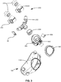
- Fig. 3 illustrates an exploded view of the hybrid mask assembly 10 so as to better illustrate the various components and how they relate with one another.
- the adapter 300 can have an inlet which receives a pressurized supply of air.
- the adapter 300 can attach to the mouth interface 100 wherein the mouth interface includes a rigid coupler 190 which facilitates attachment of the adapter 300 to a semi-flexible mask portion 110.
- the adapter 300 can also couple to nasal interface 200 by means of a flexible adapter hose 204 which attaches to an upper portion of the adapter 300 and thus provides fluid communication to a nasal extension portion 250.
- the nasal extension portion 250 can include a pair of apertures over which can be provided a pair of corresponding nasal pillow interfaces 230 which can then interface with corresponding nasal pillows 270 so as to provide a positive air pressure supply to the user's nostrils.
- the adapter 300 can include an aperture 350 and closure flap 354 which operate together to form an anti-asphyxia valve, wherein the anti-asphyxia valve is responsive to air flow, and can open in response to a zero pressurized air flow condition and then allow the user to breath air directly from the environment through the then opened anti-asphyxia valve.
- an aperture 350 and closure flap 354 which operate together to form an anti-asphyxia valve, wherein the anti-asphyxia valve is responsive to air flow, and can open in response to a zero pressurized air flow condition and then allow the user to breath air directly from the environment through the then opened anti-asphyxia valve.
- the mouth interface 100 can include a semi-flexible mask portion 110 which is configured to provide a seal around the user's mouth by transmitting a tensile sealing force applied the strap assembly 54, as shown in FIG. 1 .
- the semi flexible mask portion 110 can include a plurality of attachment mechanisms 170 which extend through an outer shell and connect to an internal support structure 130. In this manner the tensile sealing force can be applied through the semi-flexible mask portion 110 and ultimately onto a sealing membrane 150.
- the sealing membrane 150 can extend from the outer shell 112 or the internal support structure 130 from an outer perimeter of the user interface aperture 118 toward a central portion of the user interface aperture 118.
- the sealing membrane can be formed of a thin and malleable substance so as to conform to the contours of the user's face.
- the semi-flexible mask portion 110 can be formed such that the mask is semi flexible, so as to provide a comfortable fit about the user's face, wherein the internal support structure 130 provides sufficient rigidity so as to not collapse under the sealing force applied by the strap assembly, but is not so rigid so as to cause uncomfortable pressure points about the user's face.
- the internal support structure 130 operates to suspend and provide support to the relatively flexible and thin outer shell 112 which would otherwise have insufficient structural support so as to not collapse under the sealing force. This combination allows for a thinner outer shell 112 to be suspended between the interconnected truss or web structure of the internal support 130 and thus allows for a thinner exterior wall and ultimately a lighter and thus more comfortable mask.
- the attachment mechanisms can be formed as a plurality of circular grommets 170 being configured to affix to corresponding loops of a mouth strap assembly as shown in FIG. 1 .
- the connection between the circular grommets and the corresponding loops can have a rotational degree of freedom so as to increase the potential adjustability of the fit.
- the mask 110 can be provided with a plurality of malleable sealing membranes 150 and 154 being disposed about the user interface aperture of the nasal mask.
- the first malleable sealing membrane 150 can be provided so as to extend inwardly into an internal cavity of the mask from an external edge of the internal support structure 130 and the second malleable sealing membrane 154 can be provided so as to extend inwardly into the internal cavity of the mask from an internal edge of the internal support structure 130.
- the semi-flexible mask portion 110 is deformable to a certain extent it can thus be difficult to securely couple to, or in other words it will then be easy to pull away from, the otherwise relatively rigid input adapter 300.
- a rigid coupler 190 can be provided between the input adapter 300 and the semi-flexible mask portion 110 so as to facilitate a more secure connection between the two.
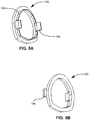
- FIGs. 5A-B illustrate a rigid coupler 190 which provides a more secure coupling to the semi-flexible mask portion as shown in FIG. 3 .
- FIGs. 6A-B illustrate how the rigid coupler 190 provides a secure interface with the rigid input adapter 300.
- the rigid coupler 190 is intended to serve as a more secure attachment means between the inlet adapter 300 and the semi-flexible mask 110.
- the rigid coupler 190 can be permanently attached to, i.e. bonded to or unitarily formed with, the semi-flexible mask 110, or alternatively the rigid coupler 190 can be removably provided to the semi-flexible mask 110 and a reliable seal provided therebetween.
- the rigid coupler 190 can be provided with a raised protrusion 198 which can interface with a corresponding channel on either the mask or the input adapter so as to provide an air tight seal therewith.
- the rigid coupler 190 can further be provided with clip 194 for interfacing with corresponding clip receivers of the inlet adapter 300, or alternatively the rigid coupler can be provided with clip slots (not shown) which can merely be pass through slots allowing the clip protrusions of the inlet adapter to interface directly with the corresponding clip interfaces of the mask itself.
- the mask 110 can be provided with a flat or otherwise consistent bonding surface for bonding to the rigid coupler 190 using adhesives or other suitable bonding agents.
- the mask 110 can be overmolded over the rigid coupler 190 so as to integrate the coupler 190 into the inlet aperture 114. If the rigid coupler 190 is formed unitarily or overmolded by the mask 110 it will then be unnecessary for both the mask and the rigid coupler to have corresponding clip interfaces.
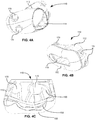
- FIGs. 6A-B illustrate a rigid input adapter 300 for use in the hybrid mask assembly discussed above.
- the rigid input adapter 300 can include an input 310 configured to receive a supply of pressurized air from a pressurized source. The flow of pressurized air enters an internal cavity and then exits the input adapter 300 from various outlets 314 and 318.
- the outlet 314 being configured to couple to the mouth interface (not shown) and the outlet 318 configured to couple to the nasal interface (not shown).
- the input adapter 300 can include a plurality of micro apertures 330 being covered by or provided as a carbon dioxide permeable membrane, such as a silicon knife coating, which allows carbon dioxide to pass therethrough, such that carbon dioxide can escape as from the mouth interface into the surrounding environment as the user exhales.
- a carbon dioxide permeable membrane such as a silicon knife coating
- FIGs. 6A-B also illustrate how the flap 354 and aperture 350 operate as an anti-asphyxia valve to prevent asphyxiation of the user if the blower stops operating.
- the inlet adapter 300 can be provided with an aperture 350 having a flat interior surface corresponding in shape to the flap 354.
- the valve flap 350 can be attached to the input adapter 300 and be configured to selectively close the aperture 350 in response to air flow through the inlet adapter 300.
- a heat moisture exchange can be provided in the form of a porous member or membrane 400.
- the HME 400 can be formed of varying materials, porous, wicking, or otherwise so as to retain exhaled moisture within the mask 110 or within the input adapter 300.
- This HME 4000 can be shaped so as to correspond in shape to the interior of the mask or input adapter and cover or force the air supply to pass therethrough such that the trapped moisture can then be partially evaporated or entrained into the inlet air supply and thus increase the moisture content of the air supply and reduce the harshness of the supplied air.
- This HME 400 can be formed in varying shapes and thicknesses so as to be adaptable for use in the input adapter disclosed herein, or alternatively, within the nasal interface.
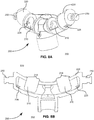
- FIGs. 8A-B illustrate isometric and cross-sectional front views of the nasal interface 200.
- the nasal interface 200 can be configured to receive positive air pressure directly from the positive air pressure adapter 300, and can be provided with trunk having an input 202 configured to connect to the flexible extension 20, as shown in FIG. 1 , so as to allow for a flexible interface between the positive air pressure adapter (not shown) and the nasal interface 200.
- the flexible connector 204 allows for easy and independent adjustment of the nasal interface 200 with respect to the varying positioning or differences in relative placement possible between a user's nares and respective mouths which can vary greatly between users. It will be appreciated that various users will have different shaped noses with varying widths and lengths, and varying distances with respect to each individual's mouth. Having a flexible interface 204 which can be provided at varying lengths allows for a consistently comfortable fit between the nasal interface 200 and the mouth interface 100.
- the nasal interface 200 can also be provided with a pair of extensions 220 that extend outwardly from a central trunk 202.
- the extensions 220 can be provided with a pair of apertures 210 over which respective right and left nasal pillow interfaces (not shown) can be provided which allow for the attachment of a pair of custom nasal pillows (not shown).
- the apertures can thus provide fluid communication from the flexible connector 204 and the input adapter (not shown) so as to provide positive air pressure through the apertures, to the nasal pillows, and into the nares of the user.
- extensions 220 can also be provided with CO2 vent holes or micro apertures 228 or other exhaust ports or holes as deemed necessary. These micro apertures can also be configured to allow carbon dioxide to pass therethrough, such that carbon dioxide can escape as from the nasal interface into the surrounding environment as the user exhales.
- the extensions can further be provided with a strap interface about distal ends of each extension configured to attach to the nasal strap assembly.
- the strap interface can be provided as tabs, as shown which can allow for a radial adjustment between the strap and the respective distal end of each extension so as to facilitate greater adjustability and therefore comfort.
- the apertures 210 can be provided with a pair of raised flanges 218 on either side about the distal edges of the apertures 210.
- the raised flanges 218 interface with corresponding internal flanges of the nasal pillow interface (not shown) which fits over the apertures 210 and provides a seal and thus transmits the pressurized air from the apertures to the nasal pillows.
- FIG. 9 illustrates an exemplary nasal pillow interface 230, which fits over the apertures as shown in FIGs. 8A-B .
- the nasal pillow interface 230 includes an inlet aperture 232 which fits over and around the extension arms 220 of FIGs. 8A-B having an interior flange 236 which interfaces against and seals with the flange 218 as shown in FIGs. 8 A-B .
- This interface allows the pillow interface 230 to rotate axially about its respective extension arm so as to increase adjustability while maintaining an air-tight seal therebetween.
- the nasal pillow interface 230 also includes an outlet aperture 234 with an interior flange 235 configured to interface with corresponding flanges on the nasal pillow (not shown here).
- the nasal pillow interface 230 can further include a rest 238 which can be provided with a pad or other soft material wherein the rest 238 can be configured to rest on the user's face between the nose and the upper lip of the user.
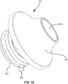
- FIG. 10 illustrates an exemplary nasal pillow 270 which can be formed having a round base portion, the base portion being provided with a plurality of flanges 274 about an inlet end 272.
- the nasal pillow 270 can be formed having an elliptical nasal cone 278 with an outlet aperture 276 which delivers the pressurized air flow to the interior of the user's nares/nostrils.
- the round base and elliptical cone allows the nasal pillow to be rotatable with respect to the nasal pillow interface 230 because the flanges 274 can interface with the interior flanges of the nasal interface outlet (not here shown) in a coaxially free manner. In this manner the user can rotate the ellipse to a comfortable position without breaking the seal.
- a plurality of such flanges 274 can be provided along their axial length so as to allow for incremental height adjustment of the individual nasal pillows with respect to their corresponding nasal pillow interfaces.
- the sealing membranes 150 and 154 can be formed separately from the mask support structure 130 allowing for different membrane stiffness and size for between various membranes. It will be further appreciated that while the present embodiments show only a sealing membrane having a plurality of interior flaps 150 and 154 respectively, however, the hybrid mask assembly 10 can be provided with numerous flaps or sheets of sealing membrane material being appropriately shaped or sized for various portions of the face wherein the separate sections are separated into circumferential portions. Alternatively, numerous flaps can be arranged in echelon having various or similar stiffnesses so as to provide a more comfortable seal.
- each of the various masks and corresponding support systems having various contours, sizes, durometer, resilience, and shapes. Additionally, each such variation to the nasal or mouth interfaces can each be formed so as to accept a uniform input adapter 300.
- the above embodiments can be formed of various materials include silicone materials, plastics, and the like. Furthermore, the durometer of each of the materials can be varied. For example, the durometer of the outer shell can be more pliable compared to the internal support structure. Alternatively, the thicknesses of the internal support structure can vary to provide the necessary mechanical coupling of a force being applied to the attachment means.
Landscapes
- Health & Medical Sciences (AREA)
- Pulmonology (AREA)
- Life Sciences & Earth Sciences (AREA)
- Animal Behavior & Ethology (AREA)
- Anesthesiology (AREA)
- Biomedical Technology (AREA)
- Heart & Thoracic Surgery (AREA)
- Hematology (AREA)
- Emergency Medicine (AREA)
- Engineering & Computer Science (AREA)
- General Health & Medical Sciences (AREA)
- Public Health (AREA)
- Veterinary Medicine (AREA)
- Otolaryngology (AREA)
- Respiratory Apparatuses And Protective Means (AREA)
- Orthopedics, Nursing, And Contraception (AREA)
Claims (14)
- Système d'interface positive avec les voies respiratoires comprenant :un adaptateur de pression d'air positive (300) qui peut se raccorder à une source de pression d'air positive ;une interface buccale (100) raccordée à l'adaptateur de pression d'air positive (300), l'interface buccale comprenant :une structure de support interne (130) ;une coque externe (112) disposée par-dessus et suspendue par la structure de support interne (130) et qui est conçue pour s'adapter par-dessus et autour de la bouche de l'utilisateur ;etune ou plusieurs membranes d'étanchéité malléables (150) disposées autour d'une ouverture d'interface avec l'utilisateur (118) ;une interface nasale (200) raccordée de manière fluidique à la source de pression d'air positive, l'interface nasale (200) comprenant :une paire d'extensions (250) s'étendant vers le haut depuis l'adaptateur de pression d'air positive (300) ; etune paire de coussinets narinaires (270), au moins un coussinet narinaire étant fixé, et correspondant, à chacune des extensions (250) ;une pluralité de moyens de fixation sur chacune de l'interface nasale (200) et de l'interface buccale (100)les moyens de fixation comprenant un mécanisme de fixation (170) s'étendant à travers la coque externe (112) et se raccordant à la structure de support interne (130), et, lors de l'utilisation, une force sur les moyens de fixation provoquant l'application de l'interface nasale (200) aux narines de l'utilisateur, et la force provoquant l'application étanche de l'interface buccale (100) autour de la bouche de l'utilisateur.
- Système d'interface positive avec les voies respiratoires selon la revendication 1, dans lequel la membrane d'étanchéité (150) est fixée à la structure de support interne (130) de l'interface buccale par application avec interférence d'un conduit formé autour d'une circonférence d'une ouverture faciale de l'interface buccale (100).
- Système d'interface positive avec les voies respiratoires selon la revendication 1, comprenant un échange de chaleur et d'humidité amovible (400) placé à l'intérieur de l'adaptateur de pression d'air positive (300).
- Système d'interface positive avec les voies respiratoires selon la revendication 2, comprenant un ou plusieurs évents d'expiration de CO2 (330) formés à travers l'adaptateur de pression d'air positive (300).
- Système d'interface positive avec les voies respiratoires selon la revendication 4, dans lequel le ou les évents d'expiration de CO2 (330) sont formés dans un insert amovible qui recouvre une ouverture avant de l'adaptateur de pression d'air positive (300).
- Système d'interface positive avec les voies respiratoires selon la revendication 2, comprenant une valve antiasphyxie (350) formée à travers l'adaptateur de pression d'air positive (300).
- Système d'interface positive avec les voies respiratoires selon la revendication 1, dans lequel le mécanisme de fixation (170) est mécaniquement couplé à la structure de support interne (130) de l'interface buccale (100).
- Système d'interface positive avec les voies respiratoires selon la revendication 1, dans lequel les mécanismes de fixation (170) sont formés d'une pluralité d'oeillets circulaires (170) qui sont conçus pour se fixer à des boucles correspondantes d'un ensemble couvre-chef.
- Système d'interface positive avec les voies respiratoires selon la revendication 7, comprenant :une première extension (250) disposée sur une première extrémité de l'interface nasale ; etune seconde extension (250) disposée sur une seconde extrémité de l'interface nasale.
- Système d'interface positive avec les voies respiratoires selon la revendication 9, comprenant un ou plusieurs ensembles sangles (50), chaque ensemble sangle (50) comprenant un premier ensemble sangle (54) conçu pour se coupler aux mécanismes de fixation buccaux (100) et un second ensemble sangle (58) conçu pour se coupler au premier et au second mécanisme de fixation nasaux (200), le ou les ensembles sangles étant conçus pour se positionner et exercer une force d'étanchéification multidimensionnelle autour du système d'interface positive avec les voies respiratoires et du visage de l'utilisateur.
- Système d'interface positive avec les voies respiratoires selon la revendication 1, comprenant :une première membrane d'étanchéité malléable (150) s'étendant vers l'intérieur dans une cavité interne du masque facial depuis un bord externe de la structure de support interne (130) ; etune seconde membrane d'étanchéité malléable (154) s'étendant vers l'intérieur dans la cavité interne du masque facial depuis un bord interne de la structure de support interne (130).
- Système d'interface positive avec les voies respiratoires selon la revendication 1, comprenant une membrane de support s'étendant d'un premier point d'une circonférence externe du masque facial à un second point de la circonférence externe du masque facial, la membrane de support étant conçue pour reposer sur une partie du maxillaire du visage de l'utilisateur entre le nez et la bouche de l'utilisateur.
- Système d'interface positive avec les voies respiratoires selon la revendication 1, dans lequel la structure de support interne (130) est formée d'éléments de treillis ou de toile interconnectés.
- Système d'interface positive avec les voies respiratoires selon la revendication 13, dans lequel la pluralité de moyens de fixation de la structure de support interne d'interface buccale (130) se fixe directement sur les éléments de treillis ou de toile interconnectés de la structure de support interne (130).
Applications Claiming Priority (2)
| Application Number | Priority Date | Filing Date | Title |
|---|---|---|---|
| US201462088825P | 2014-12-08 | 2014-12-08 | |
| PCT/US2015/064536 WO2016094429A1 (fr) | 2014-12-08 | 2015-12-08 | Système d'interface positive et hybride des voies respiratoires à utiliser avec des systèmes de ventilation et des systèmes à pression d'air positive |
Publications (2)
| Publication Number | Publication Date |
|---|---|
| EP3229882A1 EP3229882A1 (fr) | 2017-10-18 |
| EP3229882B1 true EP3229882B1 (fr) | 2019-08-07 |
Family
ID=55173942
Family Applications (1)
| Application Number | Title | Priority Date | Filing Date |
|---|---|---|---|
| EP15825881.4A Active EP3229882B1 (fr) | 2014-12-08 | 2015-12-08 | Système d'interface positive et hybride des voies respiratoires à utiliser avec des systèmes de ventilation et des systèmes à pression d'air positive |
Country Status (6)
| Country | Link |
|---|---|
| US (1) | US20160158475A1 (fr) |
| EP (1) | EP3229882B1 (fr) |
| CN (1) | CN106999686B (fr) |
| CA (1) | CA2970299A1 (fr) |
| ES (1) | ES2753575T3 (fr) |
| WO (1) | WO2016094429A1 (fr) |
Families Citing this family (10)
| Publication number | Priority date | Publication date | Assignee | Title |
|---|---|---|---|---|
| US10518057B2 (en) * | 2014-07-16 | 2019-12-31 | Human Design Medical, Llc | Facial interface and headgear system for use with ventilation and positive air pressure systems |
| CN109906098B (zh) | 2016-09-21 | 2021-12-07 | 瑞思迈私人有限公司 | 用于患者接口的换气口和换气口适配器 |
| EP3902570A2 (fr) * | 2018-12-28 | 2021-11-03 | Ethera | Masque dynamique de diffusion d'air purifie |
| WO2020188495A1 (fr) * | 2019-03-18 | 2020-09-24 | ResMed Pty Ltd | Insert de chambre de tranquillisation pour interface patient |
| WO2020240495A1 (fr) * | 2019-05-31 | 2020-12-03 | ResMed Pty Ltd | Échangeur de chaleur et d'humidité pour interface patient |
| CN215024268U (zh) * | 2019-09-10 | 2021-12-07 | 瑞思迈私人有限公司 | 患者接口,定位和稳定结构以及将患者接口连接到定位和稳定结构的保持组件 |
| WO2021081596A1 (fr) | 2019-10-30 | 2021-05-06 | ResMed Pty Ltd | Interface de patient modulaire comprenant une jonction reliant des coussins buccal et nasal |
| US12427279B2 (en) | 2020-01-14 | 2025-09-30 | ResMed Pty Ltd | Single flow and pressure activated AAV |
| US12453834B2 (en) * | 2020-05-04 | 2025-10-28 | Aeon Research And Technology, Inc. | Modular pulmonary treatment system |
| US12023445B2 (en) * | 2020-07-24 | 2024-07-02 | ResMed Pty Ltd | Standalone patient heat and moisture exchanger |
Family Cites Families (31)
| Publication number | Priority date | Publication date | Assignee | Title |
|---|---|---|---|---|
| US4782832A (en) * | 1987-07-30 | 1988-11-08 | Puritan-Bennett Corporation | Nasal puff with adjustable sealing means |
| US6644315B2 (en) * | 1999-06-18 | 2003-11-11 | Saeed Ziaee | Nasal mask |
| NZ588137A (en) * | 2003-05-02 | 2012-02-24 | Resmed Ltd | A mask system with interconnected flexible shell/cushion, rigid frame, ring member and rotatable elbow |
| US7353826B2 (en) * | 2003-08-08 | 2008-04-08 | Cardinal Health 205, Inc. | Sealing nasal cannula |
| CN101214402B (zh) * | 2003-12-31 | 2013-08-21 | 雷斯梅德有限公司 | 一种呼吸装置 |
| US8261745B2 (en) * | 2004-12-10 | 2012-09-11 | Respcare, Inc. | Ventilation interface |
| US8042539B2 (en) * | 2004-12-10 | 2011-10-25 | Respcare, Inc. | Hybrid ventilation mask with nasal interface and method for configuring such a mask |
| CN101237902B (zh) * | 2005-06-06 | 2012-02-29 | 雷斯梅德有限公司 | 面罩系统 |
| WO2007041786A1 (fr) * | 2005-10-14 | 2007-04-19 | Resmed Ltd | Ensemble nasal |
| WO2007045023A1 (fr) * | 2005-10-19 | 2007-04-26 | Resmed Ltd | Ensemble de masque nasal |
| US7448386B2 (en) * | 2005-12-07 | 2008-11-11 | Ric Investments, Llc | Full face respiratory mask with integrated nasal interface |
| GB2448644A (en) * | 2006-01-19 | 2008-10-22 | John C Jeppesen Dmd Inc | Method and device for treating sleep apnea |
| WO2008040050A1 (fr) * | 2006-10-02 | 2008-04-10 | Resmed Ltd | Coussin pour système de masque |
| WO2009052631A1 (fr) * | 2007-10-26 | 2009-04-30 | Uti Limited Partnership | Système de stabilisation de ventilation |
| CN101977656A (zh) * | 2008-01-18 | 2011-02-16 | 呼吸科技公司 | 提高无创通气效率的方法和装置 |
| US9399105B2 (en) * | 2009-04-03 | 2016-07-26 | Resmed Limited | Mask system |
| CN102049080A (zh) * | 2009-11-10 | 2011-05-11 | 崇仁(厦门)医疗器械有限公司 | 呼吸面罩 |
| US8042547B2 (en) * | 2009-11-16 | 2011-10-25 | Joseph Goldstein | Respiratory shield |
| AU2011308095B2 (en) * | 2010-09-30 | 2014-10-09 | Resmed Limited | Mask system |
| US10603456B2 (en) * | 2011-04-15 | 2020-03-31 | Fisher & Paykel Healthcare Limited | Interface comprising a nasal sealing portion |
| FR2977499B1 (fr) * | 2011-07-05 | 2013-07-12 | Georges Boussignac | Masque d'assistance respiratoire |
| US9149595B2 (en) * | 2011-11-21 | 2015-10-06 | Stuart Heatherington | Respiratory mask assembly |
| CN103974738B (zh) * | 2011-12-06 | 2017-03-15 | 皇家飞利浦有限公司 | 具有可调整稳定构件的衬垫 |
| NZ716698A (en) * | 2012-03-30 | 2017-09-29 | Resmed Ltd | Patient interface |
| CN105102049B (zh) * | 2013-03-27 | 2017-11-28 | 皇家飞利浦有限公司 | 鼻腔插管和包括该鼻腔插管的患者接口设备 |
| TWI650146B (zh) * | 2013-05-14 | 2019-02-11 | 瑞思邁有限公司 | 口鼻患者介面 |
| EP3689183A1 (fr) * | 2014-06-04 | 2020-08-05 | Revolutionary Medical Devices, Inc. | Masque de ventilation nasal et buccal combiné |
| ES2748329T3 (es) * | 2014-07-16 | 2020-03-16 | Breas Medical Inc | Sistema de interfase facial y dispositivo de cabeza para su uso con sistemas de ventilación y presión positiva de aire |
| ES2833375T3 (es) * | 2014-10-27 | 2021-06-15 | Breas Medical Inc | Mascarilla nasal para su uso en diversos sistemas de suministro de presión positiva en las vías respiratorias |
| US20160158474A1 (en) * | 2014-12-08 | 2016-06-09 | Human Design Medical, Llc | Facial mask with internal support structure for use with ventilation and positive air pressure systems |
| US10639444B2 (en) * | 2015-03-31 | 2020-05-05 | Breas Medical, Inc. | Facial mask with internal intermediate maxilla support for use with ventilation and positive air pressure systems |
-
2015
- 2015-12-08 EP EP15825881.4A patent/EP3229882B1/fr active Active
- 2015-12-08 US US14/963,005 patent/US20160158475A1/en not_active Abandoned
- 2015-12-08 ES ES15825881T patent/ES2753575T3/es active Active
- 2015-12-08 WO PCT/US2015/064536 patent/WO2016094429A1/fr not_active Ceased
- 2015-12-08 CA CA2970299A patent/CA2970299A1/fr not_active Abandoned
- 2015-12-08 CN CN201580066419.XA patent/CN106999686B/zh active Active
Non-Patent Citations (1)
| Title |
|---|
| None * |
Also Published As
| Publication number | Publication date |
|---|---|
| CA2970299A1 (fr) | 2016-06-16 |
| EP3229882A1 (fr) | 2017-10-18 |
| CN106999686A (zh) | 2017-08-01 |
| CN106999686B (zh) | 2021-12-21 |
| WO2016094429A1 (fr) | 2016-06-16 |
| ES2753575T3 (es) | 2020-04-13 |
| US20160158475A1 (en) | 2016-06-09 |
Similar Documents
| Publication | Publication Date | Title |
|---|---|---|
| EP3229882B1 (fr) | Système d'interface positive et hybride des voies respiratoires à utiliser avec des systèmes de ventilation et des systèmes à pression d'air positive | |
| US11484676B2 (en) | Unobtrusive interface system | |
| CN103153379B (zh) | 患者接口系统 | |
| US9038635B2 (en) | Ventilation mask with integrated piloted exhalation valve | |
| US9327092B2 (en) | Ventilation mask with integrated piloted exhalation valve | |
| EP1778365B1 (fr) | Masque cpap flexible | |
| EP4279109B1 (fr) | Système d'assistence respiratoire | |
| US6019101A (en) | Nasal air mask | |
| US20200206446A1 (en) | Oro-Nasal Ventilation Face Mask | |
| JP2019521821A (ja) | Cpapデバイスのための鼻用インターフェース | |
| EP3229881B1 (fr) | Masque facial ayant une structure de support interne destiné à être utilisé avec des systèmes de ventilation et de pression d'air positive | |
| US20230025941A1 (en) | Nasal respiratory mask | |
| EP3212266B1 (fr) | Masque nasal applicable dans divers systèmes de ventilation en pression positive des voies aériennes | |
| WO2015063676A1 (fr) | Dispositif d'interface patient convertible | |
| US10639444B2 (en) | Facial mask with internal intermediate maxilla support for use with ventilation and positive air pressure systems | |
| US20230030244A1 (en) | Unobtrusive interface system | |
| CN108697870B (zh) | 用于与通风和正空气压力系统一起使用的具有内部中间上颌支撑件的面罩 | |
| US20230149652A1 (en) | Nasal respiratory mask |
Legal Events
| Date | Code | Title | Description |
|---|---|---|---|
| STAA | Information on the status of an ep patent application or granted ep patent |
Free format text: STATUS: THE INTERNATIONAL PUBLICATION HAS BEEN MADE |
|
| PUAI | Public reference made under article 153(3) epc to a published international application that has entered the european phase |
Free format text: ORIGINAL CODE: 0009012 |
|
| STAA | Information on the status of an ep patent application or granted ep patent |
Free format text: STATUS: REQUEST FOR EXAMINATION WAS MADE |
|
| 17P | Request for examination filed |
Effective date: 20170608 |
|
| AK | Designated contracting states |
Kind code of ref document: A1 Designated state(s): AL AT BE BG CH CY CZ DE DK EE ES FI FR GB GR HR HU IE IS IT LI LT LU LV MC MK MT NL NO PL PT RO RS SE SI SK SM TR |
|
| AX | Request for extension of the european patent |
Extension state: BA ME |
|
| DAV | Request for validation of the european patent (deleted) | ||
| DAX | Request for extension of the european patent (deleted) | ||
| STAA | Information on the status of an ep patent application or granted ep patent |
Free format text: STATUS: EXAMINATION IS IN PROGRESS |
|
| 17Q | First examination report despatched |
Effective date: 20180702 |
|
| GRAP | Despatch of communication of intention to grant a patent |
Free format text: ORIGINAL CODE: EPIDOSNIGR1 |
|
| STAA | Information on the status of an ep patent application or granted ep patent |
Free format text: STATUS: GRANT OF PATENT IS INTENDED |
|
| INTG | Intention to grant announced |
Effective date: 20190408 |
|
| GRAS | Grant fee paid |
Free format text: ORIGINAL CODE: EPIDOSNIGR3 |
|
| GRAA | (expected) grant |
Free format text: ORIGINAL CODE: 0009210 |
|
| STAA | Information on the status of an ep patent application or granted ep patent |
Free format text: STATUS: THE PATENT HAS BEEN GRANTED |
|
| AK | Designated contracting states |
Kind code of ref document: B1 Designated state(s): AL AT BE BG CH CY CZ DE DK EE ES FI FR GB GR HR HU IE IS IT LI LT LU LV MC MK MT NL NO PL PT RO RS SE SI SK SM TR |
|
| REG | Reference to a national code |
Ref country code: GB Ref legal event code: FG4D |
|
| REG | Reference to a national code |
Ref country code: CH Ref legal event code: EP Ref country code: AT Ref legal event code: REF Ref document number: 1162860 Country of ref document: AT Kind code of ref document: T Effective date: 20190815 |
|
| REG | Reference to a national code |
Ref country code: DE Ref legal event code: R096 Ref document number: 602015035510 Country of ref document: DE |
|
| REG | Reference to a national code |
Ref country code: IE Ref legal event code: FG4D |
|
| RAP2 | Party data changed (patent owner data changed or rights of a patent transferred) |
Owner name: BREAS MEDICAL, INC. |
|
| RAP2 | Party data changed (patent owner data changed or rights of a patent transferred) |
Owner name: BREAS MEDICAL, INC. |
|
| REG | Reference to a national code |
Ref country code: SE Ref legal event code: TRGR |
|
| REG | Reference to a national code |
Ref country code: DE Ref legal event code: R081 Ref document number: 602015035510 Country of ref document: DE Owner name: BREAS MEDICAL, INC., NORTH BILLERICA, US Free format text: FORMER OWNER: HUMAN DESIGN MEDICAL, LLC, ALLSTON, US |
|
| REG | Reference to a national code |
Ref country code: NL Ref legal event code: MP Effective date: 20190807 |
|
| REG | Reference to a national code |
Ref country code: LT Ref legal event code: MG4D |
|
| PG25 | Lapsed in a contracting state [announced via postgrant information from national office to epo] |
Ref country code: FI Free format text: LAPSE BECAUSE OF FAILURE TO SUBMIT A TRANSLATION OF THE DESCRIPTION OR TO PAY THE FEE WITHIN THE PRESCRIBED TIME-LIMIT Effective date: 20190807 Ref country code: NO Free format text: LAPSE BECAUSE OF FAILURE TO SUBMIT A TRANSLATION OF THE DESCRIPTION OR TO PAY THE FEE WITHIN THE PRESCRIBED TIME-LIMIT Effective date: 20191107 Ref country code: BG Free format text: LAPSE BECAUSE OF FAILURE TO SUBMIT A TRANSLATION OF THE DESCRIPTION OR TO PAY THE FEE WITHIN THE PRESCRIBED TIME-LIMIT Effective date: 20191107 Ref country code: NL Free format text: LAPSE BECAUSE OF FAILURE TO SUBMIT A TRANSLATION OF THE DESCRIPTION OR TO PAY THE FEE WITHIN THE PRESCRIBED TIME-LIMIT Effective date: 20190807 Ref country code: PT Free format text: LAPSE BECAUSE OF FAILURE TO SUBMIT A TRANSLATION OF THE DESCRIPTION OR TO PAY THE FEE WITHIN THE PRESCRIBED TIME-LIMIT Effective date: 20191209 Ref country code: LT Free format text: LAPSE BECAUSE OF FAILURE TO SUBMIT A TRANSLATION OF THE DESCRIPTION OR TO PAY THE FEE WITHIN THE PRESCRIBED TIME-LIMIT Effective date: 20190807 Ref country code: HR Free format text: LAPSE BECAUSE OF FAILURE TO SUBMIT A TRANSLATION OF THE DESCRIPTION OR TO PAY THE FEE WITHIN THE PRESCRIBED TIME-LIMIT Effective date: 20190807 |
|
| REG | Reference to a national code |
Ref country code: AT Ref legal event code: MK05 Ref document number: 1162860 Country of ref document: AT Kind code of ref document: T Effective date: 20190807 |
|
| PG25 | Lapsed in a contracting state [announced via postgrant information from national office to epo] |
Ref country code: RS Free format text: LAPSE BECAUSE OF FAILURE TO SUBMIT A TRANSLATION OF THE DESCRIPTION OR TO PAY THE FEE WITHIN THE PRESCRIBED TIME-LIMIT Effective date: 20190807 Ref country code: AL Free format text: LAPSE BECAUSE OF FAILURE TO SUBMIT A TRANSLATION OF THE DESCRIPTION OR TO PAY THE FEE WITHIN THE PRESCRIBED TIME-LIMIT Effective date: 20190807 Ref country code: LV Free format text: LAPSE BECAUSE OF FAILURE TO SUBMIT A TRANSLATION OF THE DESCRIPTION OR TO PAY THE FEE WITHIN THE PRESCRIBED TIME-LIMIT Effective date: 20190807 Ref country code: GR Free format text: LAPSE BECAUSE OF FAILURE TO SUBMIT A TRANSLATION OF THE DESCRIPTION OR TO PAY THE FEE WITHIN THE PRESCRIBED TIME-LIMIT Effective date: 20191108 Ref country code: IS Free format text: LAPSE BECAUSE OF FAILURE TO SUBMIT A TRANSLATION OF THE DESCRIPTION OR TO PAY THE FEE WITHIN THE PRESCRIBED TIME-LIMIT Effective date: 20191207 |
|
| PG25 | Lapsed in a contracting state [announced via postgrant information from national office to epo] |
Ref country code: TR Free format text: LAPSE BECAUSE OF FAILURE TO SUBMIT A TRANSLATION OF THE DESCRIPTION OR TO PAY THE FEE WITHIN THE PRESCRIBED TIME-LIMIT Effective date: 20190807 |
|
| REG | Reference to a national code |
Ref country code: ES Ref legal event code: FG2A Ref document number: 2753575 Country of ref document: ES Kind code of ref document: T3 Effective date: 20200413 |
|
| PG25 | Lapsed in a contracting state [announced via postgrant information from national office to epo] |
Ref country code: IT Free format text: LAPSE BECAUSE OF FAILURE TO SUBMIT A TRANSLATION OF THE DESCRIPTION OR TO PAY THE FEE WITHIN THE PRESCRIBED TIME-LIMIT Effective date: 20190807 Ref country code: PL Free format text: LAPSE BECAUSE OF FAILURE TO SUBMIT A TRANSLATION OF THE DESCRIPTION OR TO PAY THE FEE WITHIN THE PRESCRIBED TIME-LIMIT Effective date: 20190807 Ref country code: DK Free format text: LAPSE BECAUSE OF FAILURE TO SUBMIT A TRANSLATION OF THE DESCRIPTION OR TO PAY THE FEE WITHIN THE PRESCRIBED TIME-LIMIT Effective date: 20190807 Ref country code: EE Free format text: LAPSE BECAUSE OF FAILURE TO SUBMIT A TRANSLATION OF THE DESCRIPTION OR TO PAY THE FEE WITHIN THE PRESCRIBED TIME-LIMIT Effective date: 20190807 Ref country code: AT Free format text: LAPSE BECAUSE OF FAILURE TO SUBMIT A TRANSLATION OF THE DESCRIPTION OR TO PAY THE FEE WITHIN THE PRESCRIBED TIME-LIMIT Effective date: 20190807 Ref country code: RO Free format text: LAPSE BECAUSE OF FAILURE TO SUBMIT A TRANSLATION OF THE DESCRIPTION OR TO PAY THE FEE WITHIN THE PRESCRIBED TIME-LIMIT Effective date: 20190807 |
|
| PG25 | Lapsed in a contracting state [announced via postgrant information from national office to epo] |
Ref country code: SK Free format text: LAPSE BECAUSE OF FAILURE TO SUBMIT A TRANSLATION OF THE DESCRIPTION OR TO PAY THE FEE WITHIN THE PRESCRIBED TIME-LIMIT Effective date: 20190807 Ref country code: IS Free format text: LAPSE BECAUSE OF FAILURE TO SUBMIT A TRANSLATION OF THE DESCRIPTION OR TO PAY THE FEE WITHIN THE PRESCRIBED TIME-LIMIT Effective date: 20200224 Ref country code: CZ Free format text: LAPSE BECAUSE OF FAILURE TO SUBMIT A TRANSLATION OF THE DESCRIPTION OR TO PAY THE FEE WITHIN THE PRESCRIBED TIME-LIMIT Effective date: 20190807 Ref country code: SM Free format text: LAPSE BECAUSE OF FAILURE TO SUBMIT A TRANSLATION OF THE DESCRIPTION OR TO PAY THE FEE WITHIN THE PRESCRIBED TIME-LIMIT Effective date: 20190807 |
|
| REG | Reference to a national code |
Ref country code: DE Ref legal event code: R097 Ref document number: 602015035510 Country of ref document: DE |
|
| PLBE | No opposition filed within time limit |
Free format text: ORIGINAL CODE: 0009261 |
|
| STAA | Information on the status of an ep patent application or granted ep patent |
Free format text: STATUS: NO OPPOSITION FILED WITHIN TIME LIMIT |
|
| PG2D | Information on lapse in contracting state deleted |
Ref country code: IS |
|
| REG | Reference to a national code |
Ref country code: CH Ref legal event code: PL |
|
| 26N | No opposition filed |
Effective date: 20200603 |
|
| REG | Reference to a national code |
Ref country code: BE Ref legal event code: MM Effective date: 20191231 |
|
| PG25 | Lapsed in a contracting state [announced via postgrant information from national office to epo] |
Ref country code: MC Free format text: LAPSE BECAUSE OF FAILURE TO SUBMIT A TRANSLATION OF THE DESCRIPTION OR TO PAY THE FEE WITHIN THE PRESCRIBED TIME-LIMIT Effective date: 20190807 Ref country code: SI Free format text: LAPSE BECAUSE OF FAILURE TO SUBMIT A TRANSLATION OF THE DESCRIPTION OR TO PAY THE FEE WITHIN THE PRESCRIBED TIME-LIMIT Effective date: 20190807 |
|
| PG25 | Lapsed in a contracting state [announced via postgrant information from national office to epo] |
Ref country code: LU Free format text: LAPSE BECAUSE OF NON-PAYMENT OF DUE FEES Effective date: 20191208 |
|
| PG25 | Lapsed in a contracting state [announced via postgrant information from national office to epo] |
Ref country code: LI Free format text: LAPSE BECAUSE OF NON-PAYMENT OF DUE FEES Effective date: 20191231 Ref country code: CH Free format text: LAPSE BECAUSE OF NON-PAYMENT OF DUE FEES Effective date: 20191231 Ref country code: BE Free format text: LAPSE BECAUSE OF NON-PAYMENT OF DUE FEES Effective date: 20191231 |
|
| PG25 | Lapsed in a contracting state [announced via postgrant information from national office to epo] |
Ref country code: CY Free format text: LAPSE BECAUSE OF FAILURE TO SUBMIT A TRANSLATION OF THE DESCRIPTION OR TO PAY THE FEE WITHIN THE PRESCRIBED TIME-LIMIT Effective date: 20190807 |
|
| PG25 | Lapsed in a contracting state [announced via postgrant information from national office to epo] |
Ref country code: HU Free format text: LAPSE BECAUSE OF FAILURE TO SUBMIT A TRANSLATION OF THE DESCRIPTION OR TO PAY THE FEE WITHIN THE PRESCRIBED TIME-LIMIT; INVALID AB INITIO Effective date: 20151208 Ref country code: MT Free format text: LAPSE BECAUSE OF FAILURE TO SUBMIT A TRANSLATION OF THE DESCRIPTION OR TO PAY THE FEE WITHIN THE PRESCRIBED TIME-LIMIT Effective date: 20190807 |
|
| PG25 | Lapsed in a contracting state [announced via postgrant information from national office to epo] |
Ref country code: MK Free format text: LAPSE BECAUSE OF FAILURE TO SUBMIT A TRANSLATION OF THE DESCRIPTION OR TO PAY THE FEE WITHIN THE PRESCRIBED TIME-LIMIT Effective date: 20190807 |
|
| P01 | Opt-out of the competence of the unified patent court (upc) registered |
Effective date: 20230528 |
|
| PGFP | Annual fee paid to national office [announced via postgrant information from national office to epo] |
Ref country code: FR Payment date: 20250930 Year of fee payment: 11 |
|
| PGFP | Annual fee paid to national office [announced via postgrant information from national office to epo] |
Ref country code: DE Payment date: 20250930 Year of fee payment: 11 |
|
| PGFP | Annual fee paid to national office [announced via postgrant information from national office to epo] |
Ref country code: GB Payment date: 20251001 Year of fee payment: 11 |
|
| PGFP | Annual fee paid to national office [announced via postgrant information from national office to epo] |
Ref country code: SE Payment date: 20251001 Year of fee payment: 11 |
|
| PGFP | Annual fee paid to national office [announced via postgrant information from national office to epo] |
Ref country code: IE Payment date: 20251001 Year of fee payment: 11 |
|
| PGFP | Annual fee paid to national office [announced via postgrant information from national office to epo] |
Ref country code: ES Payment date: 20260113 Year of fee payment: 11 |