EP3230145B1 - Verformungselement - Google Patents
Verformungselement Download PDFInfo
- Publication number
- EP3230145B1 EP3230145B1 EP15802029.7A EP15802029A EP3230145B1 EP 3230145 B1 EP3230145 B1 EP 3230145B1 EP 15802029 A EP15802029 A EP 15802029A EP 3230145 B1 EP3230145 B1 EP 3230145B1
- Authority
- EP
- European Patent Office
- Prior art keywords
- bracket
- deformation
- deformation element
- deformable element
- plate
- Prior art date
- Legal status (The legal status is an assumption and is not a legal conclusion. Google has not performed a legal analysis and makes no representation as to the accuracy of the status listed.)
- Active
Links
Images


Classifications
-
- B—PERFORMING OPERATIONS; TRANSPORTING
- B60—VEHICLES IN GENERAL
- B60R—VEHICLES, VEHICLE FITTINGS, OR VEHICLE PARTS, NOT OTHERWISE PROVIDED FOR
- B60R19/00—Wheel guards; Radiator guards, e.g. grilles; Obstruction removers; Fittings damping bouncing force in collisions
- B60R19/02—Bumpers, i.e. impact receiving or absorbing members for protecting vehicles or fending off blows from other vehicles or objects
- B60R19/24—Arrangements for mounting bumpers on vehicles
- B60R19/26—Arrangements for mounting bumpers on vehicles comprising yieldable mounting means
- B60R19/34—Arrangements for mounting bumpers on vehicles comprising yieldable mounting means destroyed upon impact, e.g. one-shot type
-
- B—PERFORMING OPERATIONS; TRANSPORTING
- B61—RAILWAYS
- B61D—BODY DETAILS OR KINDS OF RAILWAY VEHICLES
- B61D15/00—Other railway vehicles, e.g. scaffold cars; Adaptations of vehicles for use on railways
- B61D15/06—Buffer cars; Arrangements or construction of railway vehicles for protecting them in case of collisions
-
- B—PERFORMING OPERATIONS; TRANSPORTING
- B60—VEHICLES IN GENERAL
- B60R—VEHICLES, VEHICLE FITTINGS, OR VEHICLE PARTS, NOT OTHERWISE PROVIDED FOR
- B60R19/00—Wheel guards; Radiator guards, e.g. grilles; Obstruction removers; Fittings damping bouncing force in collisions
- B60R19/02—Bumpers, i.e. impact receiving or absorbing members for protecting vehicles or fending off blows from other vehicles or objects
- B60R19/03—Bumpers, i.e. impact receiving or absorbing members for protecting vehicles or fending off blows from other vehicles or objects characterised by material, e.g. composite
-
- B—PERFORMING OPERATIONS; TRANSPORTING
- B61—RAILWAYS
- B61D—BODY DETAILS OR KINDS OF RAILWAY VEHICLES
- B61D15/00—Other railway vehicles, e.g. scaffold cars; Adaptations of vehicles for use on railways
- B61D15/04—Other railway vehicles, e.g. scaffold cars; Adaptations of vehicles for use on railways convertible into other non-vehicular apparatus, e.g. exhibition stands
-
- B—PERFORMING OPERATIONS; TRANSPORTING
- B61—RAILWAYS
- B61D—BODY DETAILS OR KINDS OF RAILWAY VEHICLES
- B61D17/00—Construction details of vehicle bodies
- B61D17/04—Construction details of vehicle bodies with bodies of metal; with composite, e.g. metal and wood body structures
- B61D17/06—End walls
-
- B—PERFORMING OPERATIONS; TRANSPORTING
- B61—RAILWAYS
- B61G—COUPLINGS; DRAUGHT AND BUFFING APPLIANCES
- B61G11/00—Buffers
- B61G11/16—Buffers absorbing shocks by permanent deformation of buffer element
-
- B—PERFORMING OPERATIONS; TRANSPORTING
- B62—LAND VEHICLES FOR TRAVELLING OTHERWISE THAN ON RAILS
- B62D—MOTOR VEHICLES; TRAILERS
- B62D21/00—Understructures, i.e. chassis frame on which a vehicle body may be mounted
- B62D21/15—Understructures, i.e. chassis frame on which a vehicle body may be mounted having impact absorbing means, e.g. a frame designed to permanently or temporarily change shape or dimension upon impact with another body
-
- F—MECHANICAL ENGINEERING; LIGHTING; HEATING; WEAPONS; BLASTING
- F16—ENGINEERING ELEMENTS AND UNITS; GENERAL MEASURES FOR PRODUCING AND MAINTAINING EFFECTIVE FUNCTIONING OF MACHINES OR INSTALLATIONS; THERMAL INSULATION IN GENERAL
- F16F—SPRINGS; SHOCK-ABSORBERS; MEANS FOR DAMPING VIBRATION
- F16F7/00—Vibration-dampers; Shock-absorbers
- F16F7/12—Vibration-dampers; Shock-absorbers using plastic deformation of members
-
- F—MECHANICAL ENGINEERING; LIGHTING; HEATING; WEAPONS; BLASTING
- F16—ENGINEERING ELEMENTS AND UNITS; GENERAL MEASURES FOR PRODUCING AND MAINTAINING EFFECTIVE FUNCTIONING OF MACHINES OR INSTALLATIONS; THERMAL INSULATION IN GENERAL
- F16F—SPRINGS; SHOCK-ABSORBERS; MEANS FOR DAMPING VIBRATION
- F16F7/00—Vibration-dampers; Shock-absorbers
- F16F7/12—Vibration-dampers; Shock-absorbers using plastic deformation of members
- F16F7/123—Deformation involving a bending action, e.g. strap moving through multiple rollers, folding of members
Definitions
- the invention relates to a deformation element.
- Deformation elements are used to absorb kinetic energy in the event of collisions of vehicles, in particular passenger vehicles, which irreversibly convert the kinetic energy of the impact into deformation and thermal energy in the course of the deformation process. As a result, impulses that occur in pulses on the vehicle and subsequently on the passengers can be reduced, and the survival space of the passengers can be maintained through local and controlled energy reduction.
- these deformation elements are usually designed as part of the supporting structure, and in the case of rail vehicles, a discrete structure is also customary as a deformation element which can be produced separately.
- These deformation elements also known as crash modules, deformation modules, crumple elements or energy absorption elements, can be produced on the basis of various technologies.
- deformation elements made of metal foams or tubular deformation elements that are expanded to absorb energy are common.
- a very common operating principle is based on the progressive folding of rectangular tubes.
- Such deformation elements can be produced very easily and inexpensively and have both a well predictable energy absorption capacity and a easily calculable force level for the deformation.
- a significantly higher force is required for the start of the deformation process than for the further deformation process, which can be prevented according to the prior art by deliberately weakening the tubular energy absorber.
- the tubular energy absorber can be provided with slots, bores, ie targeted weakenings, which favor the formation of a first fold.
- US 2005/0211520 A1 is a deformation element which works according to the principle of progressive buckling, wherein a plurality of pre-deformations and recesses are provided to reduce the force for the beginning of the deformation process. These recesses prevent the occurrence of force peaks in the course of the deformation.
- this deformation element is very complex to manufacture and cannot be made watertight.
- the invention is therefore based on the object of specifying a deformation element which has a very low force peak at the beginning of the deformation process, very much is inexpensive to manufacture and can be made watertight.
- a deformation element comprising a profile tube with a rectangular cross section and a plate which closes the profile tube at one end is described, a bracket being fastened between opposite sides of the profile tube at the end of the profile tube which is closed by the plate.
- This provides the advantage of being able to ensure an initial deformation of the profiled tube when a collision opponent hits it axially, as a result of which the further deformation of the profiled tube takes place with the force level determined from the respective geometry and the material properties.
- the force peak that otherwise occurs in the deformation of profile tubes due to compressive forces in the longitudinal direction is largely eliminated, since the shape of the bracket first hits the plate and deforms it during the course of the deformation process, thereby initiating an initial deformation of the walls of the profile tube.
- the special shape of the bracket creates a tube deformation that corresponds to the natural dent pattern of a profile tube with a rectangular cross-section, ie two opposite tube surfaces bulge outwards, the other two inwards, with this dent pattern continuing alternately.
- the bracket is preferably made of sheet metal and, according to one embodiment, is shaped such that it first has a convex section, followed by a concave section, followed by a convex section, from one attachment point to the next. It can be seen convex and concave from the perspective of the profile tube in the direction of an axial collision opponent.
- the bracket must be shaped so that when a collision occurs, the concave section first touches the plate and presses it in.
- the further forced deformation of the bracket causes a deformation of the side walls of the profile tube, so that the otherwise inevitable force peak is eliminated for the further deformation.
- the bracket acts as a trigger for a progressive folding of the profile tube. This further folding of the profile tube takes place after complete deformation and flattening the bracket in accordance with the natural buckling pattern.
- the bracket has an essentially U-shaped course.
- the bracket represents an extension of the opposite side walls of the hollow tube on both sides in a first section, which are connected by means of a curved section.
- This embodiment which is simplified compared to a double S-shaped bracket, is deformed in the course of the deformation process in the first phases in such a way that an S-shaped course of the bracket also arises.
- a deformation element with a U-shaped bracket behaves practically identical to a deformation element with a double S-shaped bracket, however, due to the increased free travel in a U-shaped bracket, a slightly delayed response of the deformation element is to be expected until the hollow tube is deformed .
- a deformation element with a double S-shaped bracket offers more parameters for coordinating the Deformation behavior, however, a higher effort for the production of the double S-shaped bracket is expected.
- the profile tube is designed as a closed, rectangular hollow tube, whereby a square cross section can also be used.
- the specific shape of a deformation element according to the invention takes into account the anticipated energy to be absorbed and the available installation space.
- the wall thicknesses, the shape and the material are typically determined in the context of a computer simulation.
- the deformation element is fastened to a support structure, typically a car body of a vehicle, in accordance with the requirements of the application. Welding is also advantageous if watertightness must be ensured.
- the deformation element can be releasably attached, for example by means of a base plate and a screw connection.
- Fig. 1 shows an exemplary and schematic of a deformation element.
- a deformation element 1 is shown, which comprises a profile tube 2 and which is closed on one side by means of a plate 3. This plate 3 is arranged at that end of the profile tube 2 at which the collision opponent hits in a collision.
- the profile tube 2 is designed with a square cross section.
- the side of the profile tube 2 closed with the plate 3 is further equipped with a bracket 4.
- the bracket 4 is formed from sheet metal and extends between opposite sides of the profile tube 2.
- the bracket 4 is firmly connected at the connection points to the profile tube 2, typically welded.
- the bracket 4 follows a multiple curved shape, which is double S-shaped.
- Fig. 1 The course between the fastening points on the profile tube is given as a sequence of a convex section, followed by a concave section, followed by a further convex section. In Fig. 2 this sequence is clearly visible.
- the profile tube 2 is formed at its end facing away from the bracket 4 for attachment to a support component 5. Such a mounting option is in Fig. 1 not shown in detail.
- Fig. 2 shows an exemplary and schematic of a deformation element in a side view.
- the deformation element 1 is made of Fig. 2 shown in a side view, in which the shape of the bracket 4 is particularly clearly visible.
- the S-shaped course of the shape of the bracket 4 begins on both sides at each fastening point with the profile tube 2 with a convex section that is curved forward. Between the two convex sections there is a concave section which is curved backwards.
- the tip (the maximum) of the concave section facing the plate 3 does not touch the plate 3 but forms a certain distance from the plate 3.
- a carrier component 5 is shown, to which the deformation element 1 is attached.
- the deformation element 1 is oriented in such a way that a collision occurs in the direction of the bracket 4, to which the terms front and rear refer.
- Fig. 3 to 8 show the deformation of a deformation element in a computer simulation.
- Fig. 3 shows an exemplary and schematic of a deformation element in a simulation, stage 1. It is a Deformation element 1 shown in a grid line representation of a computer simulation.
- the deformation element 1 is similar to that in the 1 and 2 Deformation element 1 shown formed and has a substantially square profile tube 2, a plate 3 and a bracket 4.
- the opponent of the collision is not shown to illustrate the deformation process, such an opponent is in the 3 to 8 assumed to be undeformable and has a flat structure, that is to say it strikes in a planar and axial manner in the direction of the longitudinal axis of the deformation element.
- Fig. 1 shows the undeformed state before impact.
- Fig. 4 shows an example and schematically a deformation element in a simulation, stage 2. The beginning of the deformation is shown immediately after the collision opponent hits. The tip of the concave portion of the bracket 4 touches the plate 3 and begins to press it in.
- Fig. 5 shows an example and schematically a deformation element in a simulation, stage 3.
- the bracket 4 has already pressed the plate 3 deeper and the two sides of the profile tube 2 to which the bracket 4 is attached are dented by the deformation of the bracket 4 to the outside.
- the two other, opposite sides of the profile tube 2 are bent inwards by the deformed plate 3.
- Fig. 6 shows an example and schematically a deformation element in a simulation, stage 4.
- the bracket 4th is already flattened, the only progressive folding of the profile tube 2 follows.
- Fig. 7 shows an example and schematically a deformation element in a simulation, stage 5.
- the course of deformation takes place exclusively in the profile tube 2.
- the bracket 4 no longer takes part in any further deformation.
- Fig. 8 shows an example and schematically a deformation element in a simulation, stage 6. Another course of deformation, the side walls of the profile tube 2 already have two folds.
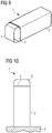
- Fig. 9 shows an example and schematically a deformation element with a U-shaped bracket.
- a deformation element 1 with a U-shaped bracket 4 is shown.
- the other components, such as the hollow tube 2 and the plate 3 correspond to that in Fig. 1 shown embodiment.
- Fig. 10 shows an exemplary and schematic of a deformation element with a U-shaped bracket in a side view.
- the deformation element 1 is made of Fig. 9 shown in a side view, in which the U-shape of the bracket 4 is particularly clearly visible.
- a carrier component 5 is shown, to which the deformation element 1 is attached.
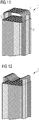
- Fig. 11 shows an example and schematically a deformation element in a simulation, stage 1.
- a deformation element 1 is shown in a grid line representation of a computer simulation.
- the deformation element 1 is similar to that in the 9 and 10 shown
- Deformation element 1 is formed and has a substantially square profile tube 2, a plate 3 and a U-shaped bracket 4.
- the opponent of the collision is not shown to illustrate the deformation process, such an opponent is in the 9 and 10 assumed to be undeformable and has a flat structure, that is to say it strikes in a planar and axial manner in the direction of the longitudinal axis of the deformation element.
- Fig. 1 shows the undeformed state before impact.
- Fig. 12 shows an example and schematically a deformation element in a simulation, stage 2. It is the deformation element from Fig. 11 shown in the next stage of the deformation process.
- the U-shaped bracket 4 is deformed by the collision opponent so that it has a double S-shaped course.
- the further deformation process follows that in the Fig. 4 to 8 shown course with a double S-shaped bracket. It is therefore not necessary to show an equivalent curve.
Landscapes
- Engineering & Computer Science (AREA)
- Mechanical Engineering (AREA)
- Transportation (AREA)
- General Engineering & Computer Science (AREA)
- Chemical & Material Sciences (AREA)
- Combustion & Propulsion (AREA)
- Life Sciences & Earth Sciences (AREA)
- Wood Science & Technology (AREA)
- Vibration Dampers (AREA)
- Body Structure For Vehicles (AREA)
Priority Applications (1)
| Application Number | Priority Date | Filing Date | Title |
|---|---|---|---|
| PL15802029T PL3230145T3 (pl) | 2014-12-11 | 2015-11-25 | Element odkształcalny |
Applications Claiming Priority (2)
| Application Number | Priority Date | Filing Date | Title |
|---|---|---|---|
| ATA50898/2014A AT515804B1 (de) | 2014-12-11 | 2014-12-11 | Verformungselement |
| PCT/EP2015/077597 WO2016091586A1 (de) | 2014-12-11 | 2015-11-25 | Verformungselement |
Publications (2)
| Publication Number | Publication Date |
|---|---|
| EP3230145A1 EP3230145A1 (de) | 2017-10-18 |
| EP3230145B1 true EP3230145B1 (de) | 2020-07-15 |
Family
ID=54754615
Family Applications (1)
| Application Number | Title | Priority Date | Filing Date |
|---|---|---|---|
| EP15802029.7A Active EP3230145B1 (de) | 2014-12-11 | 2015-11-25 | Verformungselement |
Country Status (7)
| Country | Link |
|---|---|
| US (1) | US11021121B2 (pl) |
| EP (1) | EP3230145B1 (pl) |
| AT (1) | AT515804B1 (pl) |
| CA (1) | CA2967915C (pl) |
| ES (1) | ES2824454T3 (pl) |
| PL (1) | PL3230145T3 (pl) |
| WO (1) | WO2016091586A1 (pl) |
Families Citing this family (2)
| Publication number | Priority date | Publication date | Assignee | Title |
|---|---|---|---|---|
| DE102016125554A1 (de) * | 2016-12-23 | 2018-06-28 | Voith Patent Gmbh | Zug-/Stoßeinrichtung und Kraftübertragungseinheit mit einer derartigen Zug-/Stoßeinrichtung |
| CN117108668B (zh) * | 2023-08-30 | 2026-01-06 | 东南大学 | 一种具有负刚度和负泊松比性能的三维力学超材料结构 |
Family Cites Families (17)
| Publication number | Priority date | Publication date | Assignee | Title |
|---|---|---|---|---|
| US1424359A (en) * | 1919-09-15 | 1922-08-01 | Badger Mfg Corp | Bumper bar |
| US3307868A (en) * | 1965-10-22 | 1967-03-07 | Stewart M Blank | Energy absorbing vehicle bumper assembly |
| US3782769A (en) * | 1971-06-01 | 1974-01-01 | Monroe Auto Equipment Co | Energy absorber for vehicle bumpers and the like |
| US4190276A (en) * | 1976-12-22 | 1980-02-26 | Mitsubishi Jidosha Kogyo Kabushiki Kaisha | Deformable impact absorbing device for vehicles |
| US4272114A (en) * | 1976-12-22 | 1981-06-09 | Mitsubishi Jidosha Kogyo Kabushiki Kaisha | Impact absorbing device |
| DE4302878C2 (de) * | 1992-02-15 | 2001-05-17 | Volkswagen Ag | Nach dem Stülpprinzip arbeitendes Deformationselement |
| DE29722844U1 (de) * | 1997-12-24 | 1999-04-22 | ALSTOM LHB GmbH, 38239 Salzgitter | Stoßverzehrvorrichtung mit Verformungsrohr |
| US7389860B2 (en) | 2004-03-29 | 2008-06-24 | The Texas A&M University System | Energy absorbing device having notches and pre-bent sections |
| SE0401460L (sv) * | 2004-06-09 | 2005-07-26 | Gestamp Hardtech Ab | Krockbox för fordon |
| DE102005051621B4 (de) * | 2005-10-27 | 2014-08-14 | Siemens Aktiengesellschaft | Crashelement, insbesondere für Schienenfahrzeuge |
| JP4852624B2 (ja) * | 2009-03-31 | 2012-01-11 | 株式会社日立製作所 | 衝突緩和装置を備えた軌条車輌 |
| DE102011004197A1 (de) * | 2011-02-16 | 2012-08-16 | Bayerische Motoren Werke Aktiengesellschaft | Stoßfänger für Kraftfahrzeuge mit integriertem Fußgängerschutzsystem |
| CN103717938B (zh) * | 2011-08-09 | 2017-05-17 | 新日铁住金株式会社 | 冲击吸收构件 |
| WO2013022001A1 (ja) * | 2011-08-09 | 2013-02-14 | 新日鐵住金株式会社 | 衝撃吸収部材 |
| EP2786903B1 (en) * | 2011-11-29 | 2018-03-14 | Toyota Shatai Kabushiki Kaisha | Shock-absorbing member for vehicle |
| JP5659185B2 (ja) * | 2012-04-05 | 2015-01-28 | 豊田鉄工株式会社 | 車両用衝撃吸収部材 |
| DE102013217990A1 (de) * | 2013-09-09 | 2015-03-12 | hollomet GmbH | Dämpfungskörper |
-
2014
- 2014-12-11 AT ATA50898/2014A patent/AT515804B1/de not_active IP Right Cessation
-
2015
- 2015-11-25 ES ES15802029T patent/ES2824454T3/es active Active
- 2015-11-25 PL PL15802029T patent/PL3230145T3/pl unknown
- 2015-11-25 CA CA2967915A patent/CA2967915C/en active Active
- 2015-11-25 WO PCT/EP2015/077597 patent/WO2016091586A1/de not_active Ceased
- 2015-11-25 EP EP15802029.7A patent/EP3230145B1/de active Active
- 2015-11-25 US US15/533,590 patent/US11021121B2/en active Active
Non-Patent Citations (1)
| Title |
|---|
| None * |
Also Published As
| Publication number | Publication date |
|---|---|
| ES2824454T3 (es) | 2021-05-12 |
| AT515804B1 (de) | 2015-12-15 |
| WO2016091586A1 (de) | 2016-06-16 |
| PL3230145T3 (pl) | 2020-11-30 |
| CA2967915C (en) | 2020-08-11 |
| CA2967915A1 (en) | 2016-06-16 |
| EP3230145A1 (de) | 2017-10-18 |
| AT515804A4 (de) | 2015-12-15 |
| US20180162304A1 (en) | 2018-06-14 |
| US11021121B2 (en) | 2021-06-01 |
Similar Documents
| Publication | Publication Date | Title |
|---|---|---|
| DE102015209060B4 (de) | Lenksäule für ein Kraftfahrzeug und Energieabsorptionseinrichtung | |
| WO1992001588A2 (de) | Pralldämpfer | |
| DE102013007594A1 (de) | Vorrichtung zum Absorbieren von Bewegungsenergie, insbesondere zum Einbau in ein Kraftfahrzeug | |
| DE102011011816A1 (de) | Energieabsorptionselement für einen Kraftwagen | |
| DE2460598A1 (de) | Stossdaempfungsvorrichtung | |
| EP1541424B1 (de) | Crashelement in Form eines Hohlprofils | |
| DE19712662A1 (de) | Deformationselement in einem Kraftfahrzeug, insbesondere für eine Instrumententafel | |
| WO2019020268A1 (de) | FUßGÄNGERSCHUTZVORRICHTUNG FÜR EIN FAHRZEUG | |
| AT515804B1 (de) | Verformungselement | |
| DE69400606T2 (de) | Türverstärkung für Kraftfahrzeug | |
| DE102017206277A1 (de) | Lenksäule mit Energieabsorptionsvorrichtung für ein Kraftfahrzeug | |
| DE102007057724A1 (de) | Tragkonstruktion und ein Verfahren zu deren Herstellung | |
| DE102011102630A1 (de) | Strukturelement für einen Kraftwagenaufbau | |
| DE102005051621B4 (de) | Crashelement, insbesondere für Schienenfahrzeuge | |
| DE102015200359B4 (de) | Stoßfängersystem für ein Fahrzeug und Fahrzeug | |
| DE8010342U1 (de) | Stoßfänger für Kraftfahrzeuge | |
| DE102014001232B4 (de) | Trägerprofil für eine Fahrzeugkarosserie mit unterschiedlichen Versagensmodi | |
| EP2313293B1 (de) | Absorberelement für aufprallenergie | |
| DE10031370A1 (de) | Crashenergieabsorbierende Anordnung | |
| DE10062802B4 (de) | Deformationselement für ein Kraftfahrzeug | |
| DE10340955A1 (de) | Verbindungsanordnung zwischen zwei Teilen einer Fahrzeug-Tragstruktur | |
| EP2902270B1 (de) | Stoßfänger für ein Kraftfahrzeug | |
| DE102011109425A1 (de) | Energieabsorptionselement für einen Kraftwagen | |
| DE2106963C3 (de) | Konsole zum Tragen eines Mantelrohres für eine Sicherheitslenkung eines Kraftwagens | |
| DE102012025334B4 (de) | Strukturbauteil für ein Fahrzeug zur Aufnahme von in einer Energieeinleitungsrichtung eingeleiteter kinetischer Energie |
Legal Events
| Date | Code | Title | Description |
|---|---|---|---|
| STAA | Information on the status of an ep patent application or granted ep patent |
Free format text: STATUS: THE INTERNATIONAL PUBLICATION HAS BEEN MADE |
|
| PUAI | Public reference made under article 153(3) epc to a published international application that has entered the european phase |
Free format text: ORIGINAL CODE: 0009012 |
|
| STAA | Information on the status of an ep patent application or granted ep patent |
Free format text: STATUS: REQUEST FOR EXAMINATION WAS MADE |
|
| 17P | Request for examination filed |
Effective date: 20170413 |
|
| AK | Designated contracting states |
Kind code of ref document: A1 Designated state(s): AL AT BE BG CH CY CZ DE DK EE ES FI FR GB GR HR HU IE IS IT LI LT LU LV MC MK MT NL NO PL PT RO RS SE SI SK SM TR |
|
| AX | Request for extension of the european patent |
Extension state: BA ME |
|
| DAV | Request for validation of the european patent (deleted) | ||
| DAX | Request for extension of the european patent (deleted) | ||
| RAP1 | Party data changed (applicant data changed or rights of an application transferred) |
Owner name: SIEMENS MOBILITY GMBH |
|
| RAP1 | Party data changed (applicant data changed or rights of an application transferred) |
Owner name: SIEMENS MOBILITY AUSTRIA GMBH |
|
| GRAP | Despatch of communication of intention to grant a patent |
Free format text: ORIGINAL CODE: EPIDOSNIGR1 |
|
| STAA | Information on the status of an ep patent application or granted ep patent |
Free format text: STATUS: GRANT OF PATENT IS INTENDED |
|
| INTG | Intention to grant announced |
Effective date: 20200313 |
|
| GRAS | Grant fee paid |
Free format text: ORIGINAL CODE: EPIDOSNIGR3 |
|
| GRAA | (expected) grant |
Free format text: ORIGINAL CODE: 0009210 |
|
| STAA | Information on the status of an ep patent application or granted ep patent |
Free format text: STATUS: THE PATENT HAS BEEN GRANTED |
|
| AK | Designated contracting states |
Kind code of ref document: B1 Designated state(s): AL AT BE BG CH CY CZ DE DK EE ES FI FR GB GR HR HU IE IS IT LI LT LU LV MC MK MT NL NO PL PT RO RS SE SI SK SM TR |
|
| REG | Reference to a national code |
Ref country code: CH Ref legal event code: EP Ref country code: GB Ref legal event code: FG4D Free format text: NOT ENGLISH |
|
| REG | Reference to a national code |
Ref country code: DE Ref legal event code: R096 Ref document number: 502015013035 Country of ref document: DE |
|
| REG | Reference to a national code |
Ref country code: IE Ref legal event code: FG4D Free format text: LANGUAGE OF EP DOCUMENT: GERMAN |
|
| REG | Reference to a national code |
Ref country code: AT Ref legal event code: REF Ref document number: 1290712 Country of ref document: AT Kind code of ref document: T Effective date: 20200815 |
|
| REG | Reference to a national code |
Ref country code: CH Ref legal event code: NV Representative=s name: SIEMENS SCHWEIZ AG, CH |
|
| REG | Reference to a national code |
Ref country code: LT Ref legal event code: MG4D |
|
| REG | Reference to a national code |
Ref country code: NL Ref legal event code: MP Effective date: 20200715 |
|
| PG25 | Lapsed in a contracting state [announced via postgrant information from national office to epo] |
Ref country code: BG Free format text: LAPSE BECAUSE OF FAILURE TO SUBMIT A TRANSLATION OF THE DESCRIPTION OR TO PAY THE FEE WITHIN THE PRESCRIBED TIME-LIMIT Effective date: 20201015 Ref country code: SE Free format text: LAPSE BECAUSE OF FAILURE TO SUBMIT A TRANSLATION OF THE DESCRIPTION OR TO PAY THE FEE WITHIN THE PRESCRIBED TIME-LIMIT Effective date: 20200715 Ref country code: NO Free format text: LAPSE BECAUSE OF FAILURE TO SUBMIT A TRANSLATION OF THE DESCRIPTION OR TO PAY THE FEE WITHIN THE PRESCRIBED TIME-LIMIT Effective date: 20201015 Ref country code: GR Free format text: LAPSE BECAUSE OF FAILURE TO SUBMIT A TRANSLATION OF THE DESCRIPTION OR TO PAY THE FEE WITHIN THE PRESCRIBED TIME-LIMIT Effective date: 20201016 Ref country code: FI Free format text: LAPSE BECAUSE OF FAILURE TO SUBMIT A TRANSLATION OF THE DESCRIPTION OR TO PAY THE FEE WITHIN THE PRESCRIBED TIME-LIMIT Effective date: 20200715 Ref country code: HR Free format text: LAPSE BECAUSE OF FAILURE TO SUBMIT A TRANSLATION OF THE DESCRIPTION OR TO PAY THE FEE WITHIN THE PRESCRIBED TIME-LIMIT Effective date: 20200715 Ref country code: PT Free format text: LAPSE BECAUSE OF FAILURE TO SUBMIT A TRANSLATION OF THE DESCRIPTION OR TO PAY THE FEE WITHIN THE PRESCRIBED TIME-LIMIT Effective date: 20201116 Ref country code: LT Free format text: LAPSE BECAUSE OF FAILURE TO SUBMIT A TRANSLATION OF THE DESCRIPTION OR TO PAY THE FEE WITHIN THE PRESCRIBED TIME-LIMIT Effective date: 20200715 |
|
| PG25 | Lapsed in a contracting state [announced via postgrant information from national office to epo] |
Ref country code: LV Free format text: LAPSE BECAUSE OF FAILURE TO SUBMIT A TRANSLATION OF THE DESCRIPTION OR TO PAY THE FEE WITHIN THE PRESCRIBED TIME-LIMIT Effective date: 20200715 Ref country code: RS Free format text: LAPSE BECAUSE OF FAILURE TO SUBMIT A TRANSLATION OF THE DESCRIPTION OR TO PAY THE FEE WITHIN THE PRESCRIBED TIME-LIMIT Effective date: 20200715 Ref country code: IS Free format text: LAPSE BECAUSE OF FAILURE TO SUBMIT A TRANSLATION OF THE DESCRIPTION OR TO PAY THE FEE WITHIN THE PRESCRIBED TIME-LIMIT Effective date: 20201115 |
|
| PG25 | Lapsed in a contracting state [announced via postgrant information from national office to epo] |
Ref country code: NL Free format text: LAPSE BECAUSE OF FAILURE TO SUBMIT A TRANSLATION OF THE DESCRIPTION OR TO PAY THE FEE WITHIN THE PRESCRIBED TIME-LIMIT Effective date: 20200715 |
|
| REG | Reference to a national code |
Ref country code: DE Ref legal event code: R097 Ref document number: 502015013035 Country of ref document: DE |
|
| PG25 | Lapsed in a contracting state [announced via postgrant information from national office to epo] |
Ref country code: DK Free format text: LAPSE BECAUSE OF FAILURE TO SUBMIT A TRANSLATION OF THE DESCRIPTION OR TO PAY THE FEE WITHIN THE PRESCRIBED TIME-LIMIT Effective date: 20200715 Ref country code: EE Free format text: LAPSE BECAUSE OF FAILURE TO SUBMIT A TRANSLATION OF THE DESCRIPTION OR TO PAY THE FEE WITHIN THE PRESCRIBED TIME-LIMIT Effective date: 20200715 Ref country code: SM Free format text: LAPSE BECAUSE OF FAILURE TO SUBMIT A TRANSLATION OF THE DESCRIPTION OR TO PAY THE FEE WITHIN THE PRESCRIBED TIME-LIMIT Effective date: 20200715 Ref country code: RO Free format text: LAPSE BECAUSE OF FAILURE TO SUBMIT A TRANSLATION OF THE DESCRIPTION OR TO PAY THE FEE WITHIN THE PRESCRIBED TIME-LIMIT Effective date: 20200715 |
|
| REG | Reference to a national code |
Ref country code: ES Ref legal event code: FG2A Ref document number: 2824454 Country of ref document: ES Kind code of ref document: T3 Effective date: 20210512 |
|
| PLBE | No opposition filed within time limit |
Free format text: ORIGINAL CODE: 0009261 |
|
| STAA | Information on the status of an ep patent application or granted ep patent |
Free format text: STATUS: NO OPPOSITION FILED WITHIN TIME LIMIT |
|
| PG25 | Lapsed in a contracting state [announced via postgrant information from national office to epo] |
Ref country code: AL Free format text: LAPSE BECAUSE OF FAILURE TO SUBMIT A TRANSLATION OF THE DESCRIPTION OR TO PAY THE FEE WITHIN THE PRESCRIBED TIME-LIMIT Effective date: 20200715 |
|
| 26N | No opposition filed |
Effective date: 20210416 |
|
| PG25 | Lapsed in a contracting state [announced via postgrant information from national office to epo] |
Ref country code: MC Free format text: LAPSE BECAUSE OF FAILURE TO SUBMIT A TRANSLATION OF THE DESCRIPTION OR TO PAY THE FEE WITHIN THE PRESCRIBED TIME-LIMIT Effective date: 20200715 Ref country code: SK Free format text: LAPSE BECAUSE OF FAILURE TO SUBMIT A TRANSLATION OF THE DESCRIPTION OR TO PAY THE FEE WITHIN THE PRESCRIBED TIME-LIMIT Effective date: 20200715 |
|
| PG25 | Lapsed in a contracting state [announced via postgrant information from national office to epo] |
Ref country code: LU Free format text: LAPSE BECAUSE OF NON-PAYMENT OF DUE FEES Effective date: 20201125 |
|
| PG25 | Lapsed in a contracting state [announced via postgrant information from national office to epo] |
Ref country code: SI Free format text: LAPSE BECAUSE OF FAILURE TO SUBMIT A TRANSLATION OF THE DESCRIPTION OR TO PAY THE FEE WITHIN THE PRESCRIBED TIME-LIMIT Effective date: 20200715 |
|
| PG25 | Lapsed in a contracting state [announced via postgrant information from national office to epo] |
Ref country code: IE Free format text: LAPSE BECAUSE OF NON-PAYMENT OF DUE FEES Effective date: 20201125 |
|
| PG25 | Lapsed in a contracting state [announced via postgrant information from national office to epo] |
Ref country code: MT Free format text: LAPSE BECAUSE OF FAILURE TO SUBMIT A TRANSLATION OF THE DESCRIPTION OR TO PAY THE FEE WITHIN THE PRESCRIBED TIME-LIMIT Effective date: 20200715 Ref country code: CY Free format text: LAPSE BECAUSE OF FAILURE TO SUBMIT A TRANSLATION OF THE DESCRIPTION OR TO PAY THE FEE WITHIN THE PRESCRIBED TIME-LIMIT Effective date: 20200715 |
|
| PG25 | Lapsed in a contracting state [announced via postgrant information from national office to epo] |
Ref country code: MK Free format text: LAPSE BECAUSE OF FAILURE TO SUBMIT A TRANSLATION OF THE DESCRIPTION OR TO PAY THE FEE WITHIN THE PRESCRIBED TIME-LIMIT Effective date: 20200715 |
|
| PGFP | Annual fee paid to national office [announced via postgrant information from national office to epo] |
Ref country code: BE Payment date: 20241120 Year of fee payment: 10 |
|
| PGFP | Annual fee paid to national office [announced via postgrant information from national office to epo] |
Ref country code: TR Payment date: 20241119 Year of fee payment: 10 |
|
| PGFP | Annual fee paid to national office [announced via postgrant information from national office to epo] |
Ref country code: GB Payment date: 20251211 Year of fee payment: 11 |
|
| PGFP | Annual fee paid to national office [announced via postgrant information from national office to epo] |
Ref country code: AT Payment date: 20251014 Year of fee payment: 11 |
|
| PGFP | Annual fee paid to national office [announced via postgrant information from national office to epo] |
Ref country code: IT Payment date: 20251125 Year of fee payment: 11 |
|
| PGFP | Annual fee paid to national office [announced via postgrant information from national office to epo] |
Ref country code: FR Payment date: 20251114 Year of fee payment: 11 |
|
| PGFP | Annual fee paid to national office [announced via postgrant information from national office to epo] |
Ref country code: CZ Payment date: 20251119 Year of fee payment: 11 |
|
| PGFP | Annual fee paid to national office [announced via postgrant information from national office to epo] |
Ref country code: PL Payment date: 20251114 Year of fee payment: 11 |
|
| REG | Reference to a national code |
Ref country code: CH Ref legal event code: U11 Free format text: ST27 STATUS EVENT CODE: U-0-0-U10-U11 (AS PROVIDED BY THE NATIONAL OFFICE) Effective date: 20260209 |
|
| PGFP | Annual fee paid to national office [announced via postgrant information from national office to epo] |
Ref country code: ES Payment date: 20260220 Year of fee payment: 11 |
|
| PGFP | Annual fee paid to national office [announced via postgrant information from national office to epo] |
Ref country code: DE Payment date: 20260119 Year of fee payment: 11 |
|
| PGFP | Annual fee paid to national office [announced via postgrant information from national office to epo] |
Ref country code: CH Payment date: 20260209 Year of fee payment: 11 |