EP3230175B1 - Dispositif de verrouillage pour un récipient et procédé de fabrication d'un récipient à déchets - Google Patents
Dispositif de verrouillage pour un récipient et procédé de fabrication d'un récipient à déchets Download PDFInfo
- Publication number
- EP3230175B1 EP3230175B1 EP15819952.1A EP15819952A EP3230175B1 EP 3230175 B1 EP3230175 B1 EP 3230175B1 EP 15819952 A EP15819952 A EP 15819952A EP 3230175 B1 EP3230175 B1 EP 3230175B1
- Authority
- EP
- European Patent Office
- Prior art keywords
- locking device
- mounting block
- container
- lid
- waste container
- Prior art date
- Legal status (The legal status is an assumption and is not a legal conclusion. Google has not performed a legal analysis and makes no representation as to the accuracy of the status listed.)
- Active
Links
- 239000002699 waste material Substances 0.000 title claims description 22
- 238000000034 method Methods 0.000 title claims description 8
- 230000007246 mechanism Effects 0.000 claims description 48
- 238000010168 coupling process Methods 0.000 claims description 15
- 230000008878 coupling Effects 0.000 claims description 14
- 238000005859 coupling reaction Methods 0.000 claims description 14
- 230000005291 magnetic effect Effects 0.000 claims description 4
- 230000000717 retained effect Effects 0.000 claims description 3
- 238000001514 detection method Methods 0.000 description 9
- 241001465754 Metazoa Species 0.000 description 4
- 239000000463 material Substances 0.000 description 4
- -1 recycling items Substances 0.000 description 4
- 239000002184 metal Substances 0.000 description 3
- 239000010813 municipal solid waste Substances 0.000 description 3
- 239000004033 plastic Substances 0.000 description 3
- 239000004743 Polypropylene Substances 0.000 description 2
- 230000001154 acute effect Effects 0.000 description 2
- 230000004888 barrier function Effects 0.000 description 2
- 239000003302 ferromagnetic material Substances 0.000 description 2
- 230000005484 gravity Effects 0.000 description 2
- 230000004048 modification Effects 0.000 description 2
- 238000012986 modification Methods 0.000 description 2
- 229920001155 polypropylene Polymers 0.000 description 2
- 238000004064 recycling Methods 0.000 description 2
- 239000010925 yard waste Substances 0.000 description 2
- 230000009471 action Effects 0.000 description 1
- 230000001419 dependent effect Effects 0.000 description 1
- 230000006866 deterioration Effects 0.000 description 1
- 230000009977 dual effect Effects 0.000 description 1
- 238000004519 manufacturing process Methods 0.000 description 1
- 239000007769 metal material Substances 0.000 description 1
- 230000007704 transition Effects 0.000 description 1
Images


Classifications
-
- B—PERFORMING OPERATIONS; TRANSPORTING
- B65—CONVEYING; PACKING; STORING; HANDLING THIN OR FILAMENTARY MATERIAL
- B65F—GATHERING OR REMOVAL OF DOMESTIC OR LIKE REFUSE
- B65F1/00—Refuse receptacles; Accessories therefor
- B65F1/14—Other constructional features; Accessories
- B65F1/16—Lids or covers
- B65F1/1615—Lids or covers with means for locking, fastening or permanently closing thereof
-
- E—FIXED CONSTRUCTIONS
- E05—LOCKS; KEYS; WINDOW OR DOOR FITTINGS; SAFES
- E05B—LOCKS; ACCESSORIES THEREFOR; HANDCUFFS
- E05B65/00—Locks or fastenings for special use
- E05B65/006—Locks or fastenings for special use for covers or panels
-
- E—FIXED CONSTRUCTIONS
- E05—LOCKS; KEYS; WINDOW OR DOOR FITTINGS; SAFES
- E05B—LOCKS; ACCESSORIES THEREFOR; HANDCUFFS
- E05B65/00—Locks or fastenings for special use
- E05B65/46—Locks or fastenings for special use for drawers
-
- E—FIXED CONSTRUCTIONS
- E05—LOCKS; KEYS; WINDOW OR DOOR FITTINGS; SAFES
- E05C—BOLTS OR FASTENING DEVICES FOR WINGS, SPECIALLY FOR DOORS OR WINDOWS
- E05C1/00—Fastening devices with bolts moving rectilinearly
- E05C1/08—Fastening devices with bolts moving rectilinearly with latching action
- E05C1/12—Fastening devices with bolts moving rectilinearly with latching action with operating handle or equivalent member moving otherwise than rigidly with the latch
- E05C1/14—Fastening devices with bolts moving rectilinearly with latching action with operating handle or equivalent member moving otherwise than rigidly with the latch the handle or member moving essentially towards or away from the plane of the wing or frame
-
- E—FIXED CONSTRUCTIONS
- E05—LOCKS; KEYS; WINDOW OR DOOR FITTINGS; SAFES
- E05C—BOLTS OR FASTENING DEVICES FOR WINGS, SPECIALLY FOR DOORS OR WINDOWS
- E05C19/00—Other devices specially designed for securing wings, e.g. with suction cups
- E05C19/10—Hook fastenings; Fastenings in which a link engages a fixed hook-like member
Definitions
- the present invention generally relates to a locking device for a waste container.
- Household refuse such as trash, recycling items, and/or yard waste can typically be deposited in a container.
- Such containers can include a lid for concealing the household refuse collected therein, as well as to prevent wild animals or people from accessing the household refuse and also protecting the trash from the elements.
- the lid is removably coupled to the container in a friction-fit manner to allow the lid to be easily removed from the container.
- the contents can be undesirably expelled from the container, such as if the container is toppled over such as by wind or animals.
- a strap can be coupled to the lid and the container in a snap lock fashion.
- this locking method requires a plurality of steps to secure the strap, and the strap can easily become separated from the container.
- Another exemplary locking device includes a metal coil coupled between the lid and the container to provide greater tension.
- the coil can deteriorate due to exposure to the elements.
- a locking device in accordance with the preamble of claim 1 is known from DE 10 2007 039 351 A1 .
- the present invention provides a locking device for a waste container that keeps the lid of the container closed when the container is knocked over on its side, with a sudden jerking or jarring motion, such as by impact with the ground, to prevent spillage of its contents.
- the locking device allows the lid to open when the waste container is tipped over, preferably in a forward direction, by a dumping operation.
- a locking device for a waste container according to claim 1 is provided, as well as a method for making a waste container according to claim 13.
- the container 10 is a refuse container such as a household refuse container for various items including trash, recycling, and/or yard waste.
- container 10 may be used to accommodate any type of article and may have any shape.
- container 10 may be annular or polygonal.
- container 10 may be made of various materials, such as plastic, metal, or a combination thereof.
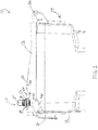
- Container 10 includes a lid 12 and a containment body 14.
- the containment body 14 defines an interior volume for holding, e.g., waste.
- the lid 12 may be separate from the containment body 14 or may be pivotally mounted to the containment body though coupling 16, such as a hinge.
- the containment body 14 may include a plurality of side walls 18.
- the lid 12 and the containment body 14 of container 10 may be made of the same or different materials.
- wheels (not shown) may be coupled to the containment body to aid in transport of the container.
- a locking device 20 is coupled to the lid 12 of the container 10.
- a first opening 22 may be formed in the lid 12 where a knob 24 of the locking device 20 can extend through the first opening 22 and a second opening 26 can be formed in the lid 12 where a fastener 28 (as illustrated in FIG. 4 ) can extend through the second opening 26 to secure the locking device 20 to the lid 12.
- the knob 24 can be secured to the lid 12 using various coupling techniques.
- a first flange 30 may be disposed on a top surface 32 of the lid 12 of the container 10 and a second flange 34 can be disposed on a bottom surface 36 of the lid 12 of the container 10 where the second flange 34 is threaded onto a post 38 coupled to the knob 24.
- the location of the first flange 30 and/or the second flange 34 may be adjustable based on the thickness of the lid 12.
- the fastener 28 includes a flange portion 40 that when mounted is disposed above the top surface 32 of the lid 12.
- the flange portion 40 of the fastener 28 has a greater diameter than the second opening 26 formed in the lid 12.
- the fastener 28 may further include a post 42 coupled to and extending through the housing 44 of the locking device below the bottom surface 36 of the lid 12. Overall, the mounting of the locking device 20 is such that a part of the locking device protrudes above the lid, and thus outside of container 10, as best illustrated in FIGS. 1-3 .
- the locking device 20 is preferably positioned towards the front of the lid 12 for reasons to be apparent below.
- the locking device 20 interacts with a latch 46 coupled to the containment body 14 to secure the lid 12 to the containment body 14.
- the latch 46 is coupled to an inner surface 48 of any one of the side walls 18 of the containment body 14, preferably on the side wall opposing the side wall to which the coupling 16 is attached.
- Latch 46 may be made of various materials such as plastic, metal, high density polypropylene, etc.
- the latch 46 has an elongated body 50 where a first end 52 of the elongated body 50 is coupled to the inner surface 48 of the side wall 18 through opening 54 using, e.g. a mechanical fastener, such as a bolt, screw, or the like (not shown).
- a mechanical fastener such as a bolt, screw, or the like (not shown).
- the elongated body 50 may be angled to extend away from the inner surface 48 of the side wall 18.
- a protrusion 56 may extend from a second end 58 of the elongated body 50 of the latch 46 where the protrusion 56 extends through an opening 60 in the side wall 18.
- One end 62 of the protrusion 56 extends below the opening 60 in the side wall such that the elongated body 50 is elastically deformable when the locking device 20 engages the latch 46.
- the end 62 of the protrusion 56 that extends below the opening 60 in the side wall 18 is positioned to prevent the second end 58 of the elongated body 50 of the latch 46 from separating from the side wall 18 without using a fastener.
- each latch 46 is mounted so as to not to interfere with an adjacent nested containment body 14.
- Latch 46 may be coupled to the containment body 14 during the manufacturing process of the containment body 14, after an end user receives the containment body 14, or any time in-between.
- latch 46 may be integrally formed with a sidewall 18 of the containment body 14.
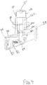
- the locking device 20 may include the knob 24, a slide trigger 64, a weighted mechanism 66, and the housing 44.
- the knob 24 includes an actuation device, e.g. at least one pressure sensitive button 68.
- knob 24 includes two pressure sensitive buttons 68, 70 where each of the buttons 68, 70 is coupled to a protrusion 72 or 74, respectively.
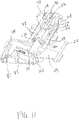
- the first protrusion 72 has a first slit 76; and the second protrusion 74 has a second slit 78 (as best illustrated in FIGS. 5 and 11 ).
- the first slit 76, formed in the first protrusion 72 associated with the first button 68, is angled in a first direction; and the second slit 78, formed in the second protrusion 74 associated with the second button 70, is angled in a second direction, such that a first portion of the first slit 76 overlaps a first portion of the second slit 78.
- the protrusions 72, 74 are displaced and the slits 76, 78 align to allow a pin 81 extending approximately horizontally through both the first slit 76 and the second slit 78 to slide into a second position as illustrated in FIGS. 6 and 12 .
- the slide trigger 64 is configured to slidably engage with latch 46.
- the slide trigger 64 includes at least three projections 80, 82, 84 that extend from a body portion 86.
- a first projection 80 is associated with the latch 46;
- a second projection 82 is associated with a biasing device 88, such as a spring; and
- a third projection 84 is associated with the weighted mechanism 66.
- slide trigger 64 is shown to have a size, shape, and configuration as illustrated in FIGS. 5-12
- slide trigger 64 may have any size, shape, and/or configuration that allows the locking device 20 to engage with latch 46 when the locking device 20 is actuated into a locked position.
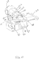
- the first projection 80 of the slide trigger 64 is configured to engage with an opening 90 (see FIG. 4 ) in the latch 46 when the locking device 20 is in the locked position.
- the first projection 80 forms a hook that mates to the opening 90 in the latch 46.
- the first projection 80 includes a first surface 92 and a second surface 94 arranged at an acute angle to each other, such as about 20-80°, preferably about 25-45°.
- the first projection 80 may further include a third surface 96 that is approximately similar to the underlying surface configuration of the housing 44.
- the third surface 96 may be substantially parallel to the underlying surface of the housing 44 such that when the slide trigger 64 is actuated, the third surface 96 does not contact the housing. Overall, the surfaces 92, 94, 96 form a hook for engagement with the opening 90 in the latch 46.
- the second projection 82 of the slide trigger 64 is configured to engage with the biasing device 88.
- the biasing device 88 may be a coil spring.
- the biasing device 88 provides a mechanical biasing force to the slide trigger 64, such that when the locking device is in the locked position, the slide trigger 64 is urged into engagement with the latch 46, and when the locking device is in an unlocked position, the slide trigger 64 is urged into disengagement with the latch 46.
- the third projection 84 of the slide trigger 64 is configured to engage with the weighted mechanism 66.
- the third projection 84 includes a first surface 98 and a second surface 100.
- the first surface 98 contacts a side surface 102 of the weighted mechanism 66 and when the locking device is in the unlocked position, the second surface 100 contacts the bottom surface 104 of the weighted mechanism 66.
- the weighted mechanism 66 is configured to provide counter balance to the locking mechanism.
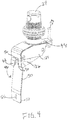
- the weighted mechanism 66 includes a mounting block 106, a slide weight 108 extending from the bottom of the mounting block 106, and one or more impact detection paddles 110 retained on the mounting block 106, as best shown in FIG. 5 .
- the paddles 110 are placed equiangularly around the circumference of the mounting block 106.
- two or more paddles 110 are provided, more preferably two to eight, and most preferably four.
- Paddles 110 preferably resemble rectangular bars.
- the mounting block 106 and the plurality of impact detection paddles 110 may be made of the same material, such as plastic or high density polypropylene, and the slide weight 108 may be made of a metal material, and may resemble a pipe.
- the mounting block 106 includes a projection 112 having a slot 114 where a pin 81 is disposed in the slot 114 of the projection 112 associated with the mounting block 106 and extends through the first and second slits 76, 78 of the knob 24.
- the mounting block 106 may have any shape or arrangement. In an exemplary embodiment, as best illustrated in FIGS. 11 and 12 , the mounting block 106 may have a shape having four sides where an impact detection paddle 110 is coupled to each side of the mounting block 106.
- Each impact detection paddle 110 may be mounted to a side of the mounting block 106 where each paddle 110 is recessed from an outer surface 116 of the mounting block 106 such that the outer surface 118 of each paddle 110 is substantially flush with the outer surface 116 of the mounting block 106.
- Each paddle 110 may be rotatably coupled to the mounting block at a lower portion of the paddle 110 with a rotatable coupling 120, such as a hinge. The upper end of the paddle 110 is detachably retained to the mounting block 106 by a bias force.
- the paddle 110 when the upper end of the paddle 110 is attached to the mounting block 106, it is parallel to a center axis of the mounting block, such that when mounted on a container 10, the paddle 110 is approximately parallel to a center line extend between the center of the top and bottom of the container 10. Conversely, when the upper end of the paddle 110 is detached the mounting block 106, the paddle 110 lays at an angle, preferably an acute angle, to the center line.
- the rotatable coupling 120 provides a bias force to prevent the upper end of the paddle 110 from rotating away and detaching from the mounting block unless a force greater than the bias force is introduced.
- the bias force may be provided at the rotatable coupling 120 by a spring.
- the paddle 110 rotates about the pivot point at the point of coupling with the mounting block 106 such that an upper portion of the paddle 110 is located outside the plane of the outer surface 116 of the mounting block 106, as best shown in FIGS. 8 and 9 .
- the bias force is less than the gravitational force on the paddle 110, when the locking device 20 is on its side, e.g. when the container 10 is knocked over on its side.
- the paddle 110 When a paddle 110 has been actuated to an extended position (rotated away from the mounting block 106), if the mounting block 106 attempts to move in an upward direction, the paddle 110 will abut a barrier structure 122 formed in the locking mechanism housing 44 to prevent the mounting block 106 from triggering disengagement of the locking mechanism 20.
- the paddle 110 may contain a notch at the lower portion of the paddle 110 to provide sufficient flexibility to allow the paddle 110 to be snapped on to the rotatable coupling 120.
- the bias force to keep the paddle from rotating away and detach from the mounting block 106 may be magnetic.
- a magnet may be place at an upper portion of the paddle 110 opposing the rotatable coupling to magnetically hold the paddle 110 and prevent paddle 110 from rotating away from the mounting block 106.
- the upper portion of the paddle 110 pulls away from the mounting block 106 by pivoting on the rotatable coupling 120.
- the magnetic force is not sufficient to prevent the paddle 110 from rotating away from the mounting block 106 when the locking device 20 is on its side, e.g. when the container 10 is knocked over on its side.
- a magnet may be permanently placed on the upper end of each paddle 110 and a ferromagnetic material may be used as part of the mounting block 106.
- the magnet may be placed on the mounting block 106 and a ferromagnetic material placed on the upper end of the paddle 110.
- the weighted mechanism 66 can be actuated using gravity. For example, when the lid 12 is in a closed position and the container 10 is upright, the slide weight 108 extends downwardly from the mounting block 106 as illustrated in FIG. 8 (a locked position of the weighted mechanism). When container 10 is rotated into a dumping position, the weighted mechanism 66 slides upwardly toward the knob as illustrated in FIG. 7 (this is an opened position of the weighted mechanism).
- the weighted mechanism 66 may be coupled to the mounting block 106, such that when the two buttons 68, 70 on the knob 24 are pressed and the weighted mechanism 66 moves upwardly toward the knob 24 (opened position) to allow the slide trigger 64 to be disengaged from the latch 46.
- the housing 44 may be configured to enclose the locking mechanism 20.
- the housing 44 may include at least one cover 124 and a latch opening 126 where the protrusion 56 that extends from a second end 58 of the elongated body 50 of the latch 46 is recessed within the latch opening 126 and the sides of the latch opening 126 surround the second end 58 of the elongated body 50 of the latch 46.
- the latch opening 126 may be a groove formed in the housing 44 such that the second end 58 of the latch 46 engages with the groove formed in the housing 44.
- mounting recesses 128 are formed in the housing 44 wherein a coupling device can engage the mounting recesses 128 to secure the cover 124 to the housing.
- lid 12 of the container 10 is in contact with and encloses the containment body 14.
- the slide trigger 64 is biased to engage with the latch 46, and the slide weight 108 extends downwardly from the mounting block 106 and blocks the slide trigger 64 from sliding away from the latch 46.
- each of the plurality of impact detection paddles 110 is within the corresponding recess formed in the mounting block 106.
- the weighted mechanism 66 hangs downwardly on the pin 81 with the slide weight 108 in position to block the slide trigger 64 from sliding away from the latch 46.
- the jerking or jarring action such as ground impact
- the container 10 when the container 10 is knocked over on its side, e.g. by strong wind or animals, while in the locked position, the jerking or jarring action, such as ground impact, on the container 10, actuates one or more of the impact detection paddles 110 to extend from the outer surface 116 of the mounting block 106 (the paddle 110 pivots away from the mounting block 106), as illustrated in FIGS. 8 and 9 .
- the container 10 may fall to the ground such that one of the side walls 18 impacts the ground with a jerking or jarring motion.
- a paddle 110 corresponding to the side wall 18 that contacts the ground is engaged after the sidewall 18 impacts the ground, i.e.
- the paddle 110 is pulled away from its associated recess and pivots away from the mounting block 106.
- the engaged paddle 110 prevents the lid 12 from opening by preventing the weighted mechanism 66 from sliding toward the knob 24.
- the abutment of the engaged paddle 110 and the barrier structure 122 prevents the slide weigh 108 from sliding upwardly toward the knob 24 to allow the slide trigger 64 to be disengaged from the latch 46.
- the paddle 110 remains attached to the mounting block 106. That way, the lid 12 may be opened manually by pushing on the pressure sensitive buttons 68, 70, or when the waste container is inverted, gravity allows the lid 12 to open by pulling the weighted mechanism 66 toward the knob 24.
- the weighted mechanism 66 and its paddles 110 thus, provide a mechanical sensor that can detect whether the container 10 has been unintendedly tipped over or whether it is being tipped over, such as for dumping.
- the weighed mechanism 66 provides a mechanical sensor that detects unintended tipping of waste container 10 regardless of the direction or distance of tipping.
- four (4) paddles 110 are equiangularly disposed about mounting block 106, such that each paddle 100 may be oriented with one of the side walls 18 where the container 10 is rectangular.
- the slide weight 108 (and the rest of the weighted mechanism 66) slide toward the knob 24 to allow the slide trigger 64 to disengage from the latch 46.
- the two pressure sensitive buttons 68, 70 in the knob 24 are engaged the corresponding protrusions 72, 74 are displaced causing the pin 81 of the weighted mechanism 66 to slide from a first position at the lower portions of the slits 76, 78 to a second position at an upper portions of the slits 76, 78.
- the weighted mechanism 66 is pulled toward the knob 24 to allow the slide trigger 64 to disengage from the latch 46 where the slide weight 108 rests on the top surface 100 of the third projection 84.
- the impact detection paddles 110 prevent the lock from unlocking when the container 10 falls over and impacts the ground in any direction.
- any impact detection paddle 110 that is actuated to extend from the mounting housing 106 during impact will be returned to the unlock position within the recess of the mounting housing 106 when the container 10 is returned to the upright position.
- removal of the contents of the container 10 may be performed in any direction.
- the container 10 may be dumped in any direction when picked up by an automated arm. No additional devices such as keys are needed to actuate the locking mechanism 20, such that the container can be locked and unlocked directly at the container 10 without any additional device.
- Latch 46 may be mounted inside of the container body 14 such that when a plurality of containers are nested, each latch 46 is pressed flat against an associated side wall. Moreover, the locking mechanism 20 is mounted to the lid 12 of the container 10 thereby separating the locking mechanism 20 from the waste stream to prevent undesired deterioration.
Landscapes
- Engineering & Computer Science (AREA)
- Mechanical Engineering (AREA)
- Refuse Receptacles (AREA)
- Closures For Containers (AREA)
Claims (13)
- Dispositif de verrouillage (20) pour un conteneur à déchets (10), le dispositif de verrouillage (20) comprenant un mécanisme à poids (66) pouvant être déplacé entre une position verrouillée et une position ouverte, la position ouverte permet au dispositif de verrouillage (20) d'être déverrouillé et la position verrouillée garde le dispositif de verrouillage (20) verrouillé, où le mécanisme à poids (66) contient une ou plusieurs plaques (110), chaque plaque (110) présentant des première et seconde extrémités opposées, la première extrémité est montée sur un bloc de montage (106) au moyen d'un accouplement rotatif (120) et la seconde extrémité est retenue de manière séparable sur une surface du bloc de montage (106), de sorte que lorsque la seconde extrémité est détachée de la surface, elle peut être positionnée pour empêcher le mécanisme à poids (66) d'être déplacé à la position non verrouillée ; un élément de déclenchement coulissant (64) ; et un loquet (46), où l'élément de déclenchement coulissant (64) est engagé avec le loquet (46) lorsque le mécanisme à poids (66) se trouve à la position verrouillée et est libéré du loquet (46) lorsque le mécanisme à poids se trouve à la position ouverte, caractérisé en ce qu'une force de sollicitation retient de manière séparable la seconde extrémité de la plaque (110) sur la surface du bloc de montage (106).
- Dispositif de verrouillage selon la revendication 1, dans lequel a) chaque plaque (110) est montée dans un évidement sur un côté du bloc de montage (106) ; et b) de deux à huit plaques (110) sont disposées de manière équiangulaire autour d'un périmètre du bloc de montage (106).
- Dispositif de verrouillage selon la revendication 1, dans lequel la force de sollicitation est assurée par un ressort au niveau de l'accouplement rotatif ou par attraction magnétique.
- Dispositif de verrouillage selon l'une quelconque des revendications 1-3, dans lequel le mécanisme à poids (66) comprend en outre un poids coulissant (108), de sorte que lorsque le mécanisme à poids (66) se trouve à la position verrouillée, le poids coulissant (108) empêche l'élément de déclenchement coulissant (64) de se libérer du loquet.
- Dispositif de verrouillage selon l'une quelconque des revendications 1-4, comprenant en outre un bouton (24) au-dessus du mécanisme à poids (66), le bouton (24) contient un dispositif d'actionnement pour positionner manuellement le mécanisme à poids (66) à la position ouverte.
- Dispositif de verrouillage selon l'une quelconque des revendications 1-5, dans lequel le bloc de montage (106) contient en outre une protubérance présentant une fente en son sein, la fente est couplée au dispositif d'actionnement via une broche (81).
- Conteneur à déchets (10) comprenant un corps de contenance (14), un couvercle (12) attaché au corps de contenance (14) par une articulation, le couvercle (12) comprenant le dispositif de verrouillage (20) selon la revendication 1 monté en son sein.
- Conteneur à déchets selon la revendication 7, dans lequel a) le dispositif de verrouillage (20) garde le couvercle (12) fermé lorsque le conteneur à déchets (10) chute au sol et heurte le sol selon une quelconque direction ; et b) le dispositif de verrouillage (20) est monté dans une découpe dans le couvercle (12).
- Conteneur à déchets selon l'une quelconque des revendications 7 et 8, dans lequel a) la plaque (110) est montée dans un évidement sur un côté du bloc de montage (106) ; ou b) de deux à huit plaques (110) sont disposées de manière équiangulaire autour d'un périmètre du bloc de montage (106).
- Conteneur à déchets selon l'une quelconque des revendications 7-9, dans lequel le mécanisme à poids (66) comprend en outre un poids coulissant (108), de sorte que lorsque le mécanisme à poids (66) se trouve à la position verrouillée, le poids coulissant (108) empêche l'élément de déclenchement coulissant (64) de se libérer du loquet.
- Conteneur à déchets selon l'une quelconque des revendications 7-10, comprenant en outre un bouton (24) au-dessus du mécanisme à poids (66), le bouton (24) contient un dispositif d'actionnement pour positionner manuellement le mécanisme à poids (66) à la position ouverte.
- Conteneur à déchets selon l'une quelconque des revendications 7-11, dans lequel le bloc de montage (106) contient en outre une protubérance présentant une fente en son sein, la fente est couplée au dispositif d'actionnement via une broche (81).
- Procédé de fabrication d'un conteneur à déchets (10), comprenant les étapes consistant à :a. fournir le conteneur à déchets (10) contenant un corps de contenance (14), et un couvercle (12) attaché au corps de contenance (14) par une articulation ; etb. monter le dispositif de verrouillage (20) selon la revendication 1 dans une découpe du couvercle (12).
Applications Claiming Priority (2)
| Application Number | Priority Date | Filing Date | Title |
|---|---|---|---|
| US201462089591P | 2014-12-09 | 2014-12-09 | |
| PCT/US2015/064636 WO2016094485A1 (fr) | 2014-12-09 | 2015-12-09 | Dispositif de verrouillage pour un récipient |
Publications (2)
| Publication Number | Publication Date |
|---|---|
| EP3230175A1 EP3230175A1 (fr) | 2017-10-18 |
| EP3230175B1 true EP3230175B1 (fr) | 2020-04-29 |
Family
ID=55069108
Family Applications (1)
| Application Number | Title | Priority Date | Filing Date |
|---|---|---|---|
| EP15819952.1A Active EP3230175B1 (fr) | 2014-12-09 | 2015-12-09 | Dispositif de verrouillage pour un récipient et procédé de fabrication d'un récipient à déchets |
Country Status (5)
| Country | Link |
|---|---|
| US (1) | US10202238B2 (fr) |
| EP (1) | EP3230175B1 (fr) |
| AU (1) | AU2015360671A1 (fr) |
| CA (1) | CA2973337C (fr) |
| WO (1) | WO2016094485A1 (fr) |
Cited By (1)
| Publication number | Priority date | Publication date | Assignee | Title |
|---|---|---|---|---|
| CN112252859A (zh) * | 2020-11-28 | 2021-01-22 | 国网河南省电力公司南阳供电公司 | 一种表箱用锁具和钥匙 |
Families Citing this family (9)
| Publication number | Priority date | Publication date | Assignee | Title |
|---|---|---|---|---|
| US9963276B1 (en) * | 2014-04-25 | 2018-05-08 | The Eastern Company | Latch and release mechanisms for waste containers |
| CA2995352C (fr) | 2015-08-10 | 2024-05-21 | Serio-Us Industries, Inc. | Dispositif de verrouillage pour recipient pour ordures |
| US10597227B2 (en) * | 2016-04-07 | 2020-03-24 | Franzen Canada Corp. | Dustbin lock assembly |
| USD789770S1 (en) | 2016-06-02 | 2017-06-20 | Serio-Us Industries, Inc. | Container lock |
| USD898546S1 (en) * | 2018-03-02 | 2020-10-13 | G.T. Line S.R.L. | Locking and unlocking device |
| CN109809062A (zh) * | 2019-03-26 | 2019-05-28 | 湖北延昌机械设备有限公司 | 勾臂垃圾箱及垃圾清运系统 |
| CN113233049B (zh) * | 2021-06-21 | 2023-08-18 | 湖北延昌机械设备有限公司 | 一种可监控垃圾桶内垃圾满溢程度的智能垃圾分类箱 |
| CN114194665B (zh) * | 2021-11-23 | 2024-03-22 | 中国人民解放军联勤保障部队第九二三医院 | 感应式医疗垃圾回收装置 |
| CN119457018B (zh) * | 2025-01-14 | 2025-04-29 | 贵州大学 | 一种用于建筑爬架链条的金属棒铸造装置 |
Family Cites Families (29)
| Publication number | Priority date | Publication date | Assignee | Title |
|---|---|---|---|---|
| US3530696A (en) * | 1968-03-07 | 1970-09-29 | Christy Concrete Products Inc | Gravity latch for box lid |
| US3674298A (en) | 1970-10-30 | 1972-07-04 | Balazs Vekony | Garbage can lid lock |
| FR2675478A1 (fr) | 1991-04-17 | 1992-10-23 | Plastic Omnium Cie | Dispositif de verrouillage d'un couvercle sur une cuve de conteneur et conteneur comprenant un tel dispositif. |
| US5415314A (en) | 1993-06-21 | 1995-05-16 | Mccollum; Chris A. | Gravity locking mechanism employing first and second pendulums for securing the lid of a refuse container |
| US5419598A (en) * | 1994-04-28 | 1995-05-30 | Kreitzer; Joseph D. | Lock for trash bin |
| US5772061A (en) | 1994-12-15 | 1998-06-30 | Egbert H. Taylor & Company Limited | Refuse containers |
| US5599050A (en) | 1995-09-27 | 1997-02-04 | Tinsley; Harry | Lid-locking device for trash containers |
| US5772264A (en) | 1996-03-25 | 1998-06-30 | Bettenhausen; Shane | Gravity operated latch for a refuse container lid |
| DE19707759C1 (de) * | 1997-02-26 | 1998-08-20 | Fuss Fritz Gmbh & Co | Sperr-/Freigabevorrichtung für eine Schwenkfalle eines Arbeitsstrom-Türöffners |
| FR2798120B1 (fr) | 1999-09-03 | 2001-11-16 | Citec Environnement | Dispositif automatique par gravite de verrouillage/ deverrouillage du couvercle d'un bac et bac equipe d'un tel dispositif |
| US6808080B2 (en) | 2002-03-08 | 2004-10-26 | Delaware Capital Formation, Inc. | Container latching method and apparatus |
| CA2406301A1 (fr) | 2002-10-02 | 2004-04-02 | Warren Thomas Walker | Systeme de fixation de couvercle de poubelle |
| US7086557B2 (en) | 2003-09-22 | 2006-08-08 | Gill Industries, Inc. | Animal resistant trash container lid and trash container system |
| DE102004008348B3 (de) * | 2004-02-22 | 2005-10-20 | Fuss Fritz Gmbh & Co | Sperr-/Freigabevorrichutng für eine Schwenkfalle eines Türöffners |
| CA2533193A1 (fr) * | 2006-01-19 | 2007-07-19 | Bear Necessities Waste & Food Storage Inc. | Mecanisme de caisse et de couvercle a l'epreuve des animaux |
| US7603882B2 (en) * | 2006-09-15 | 2009-10-20 | Anthony, Inc. | Electric door lock system for refrigerated display cases |
| US20080169288A1 (en) | 2007-01-12 | 2008-07-17 | Michael Dawn | Receptacle having a securable lid |
| DE102007039351B4 (de) * | 2007-05-03 | 2026-02-12 | S. Franzen Söhne GmbH | Mülltonnenverschluss |
| US8485382B2 (en) | 2008-03-07 | 2013-07-16 | Orbis Canada Limited | Refuse container |
| US8313126B2 (en) | 2008-10-23 | 2012-11-20 | Hodge Products, Inc. | Gravity release locking apparatus for trash container |
| US9346616B2 (en) * | 2010-09-07 | 2016-05-24 | Rehrig Pacific Company | Waste container with improved latch |
| US20120273495A1 (en) | 2011-04-27 | 2012-11-01 | D Alessandro Lorraine | Animal Deterrent Trash System |
| US8810361B2 (en) | 2011-08-09 | 2014-08-19 | Shervin Moloudi | Electronically augmented smart lock for trash containers |
| US20140069926A1 (en) * | 2012-09-13 | 2014-03-13 | Northland Products, Inc. | Latch system with inertial lock mechanism |
| US9828177B2 (en) * | 2013-02-22 | 2017-11-28 | Orbis Corporation | Waste container with gravity latch and latch deactivation system |
| US9376255B2 (en) | 2013-02-22 | 2016-06-28 | Orbis Corporation | Waste container with gravity latch |
| US9260891B2 (en) * | 2013-12-10 | 2016-02-16 | Myers Industries, Inc. | Container with gravity releasable locking lids |
| US10100554B2 (en) * | 2014-08-26 | 2018-10-16 | Northland Products, Inc. | Gravity-actuated latch mechanism |
| US9738445B2 (en) * | 2015-04-10 | 2017-08-22 | Rehrig Pacific Company | Roll out cart with gravity lock |
-
2015
- 2015-12-09 US US14/963,483 patent/US10202238B2/en active Active
- 2015-12-09 AU AU2015360671A patent/AU2015360671A1/en not_active Abandoned
- 2015-12-09 EP EP15819952.1A patent/EP3230175B1/fr active Active
- 2015-12-09 WO PCT/US2015/064636 patent/WO2016094485A1/fr not_active Ceased
- 2015-12-09 CA CA2973337A patent/CA2973337C/fr active Active
Non-Patent Citations (1)
| Title |
|---|
| None * |
Cited By (2)
| Publication number | Priority date | Publication date | Assignee | Title |
|---|---|---|---|---|
| CN112252859A (zh) * | 2020-11-28 | 2021-01-22 | 国网河南省电力公司南阳供电公司 | 一种表箱用锁具和钥匙 |
| CN112252859B (zh) * | 2020-11-28 | 2022-02-22 | 国网河南省电力公司南阳供电公司 | 一种表箱用锁具和钥匙 |
Also Published As
| Publication number | Publication date |
|---|---|
| EP3230175A1 (fr) | 2017-10-18 |
| CA2973337A1 (fr) | 2016-06-16 |
| US20160159569A1 (en) | 2016-06-09 |
| WO2016094485A1 (fr) | 2016-06-16 |
| CA2973337C (fr) | 2023-01-03 |
| AU2015360671A1 (en) | 2017-07-27 |
| US10202238B2 (en) | 2019-02-12 |
Similar Documents
| Publication | Publication Date | Title |
|---|---|---|
| EP3230175B1 (fr) | Dispositif de verrouillage pour un récipient et procédé de fabrication d'un récipient à déchets | |
| CA2973338C (fr) | Dispositif de verrouillage pour un conteneur | |
| US9376255B2 (en) | Waste container with gravity latch | |
| US9828177B2 (en) | Waste container with gravity latch and latch deactivation system | |
| US8881930B2 (en) | Refuse container | |
| US6666485B1 (en) | Device for locking/unlocking by gravity, the lid of a container and a container equipped therewith | |
| US20170320666A1 (en) | Locking device for container | |
| US9260891B2 (en) | Container with gravity releasable locking lids | |
| CA2995352C (fr) | Dispositif de verrouillage pour recipient pour ordures | |
| US11745942B2 (en) | Locking device for waste container and methods | |
| US20180044941A1 (en) | Tamper resistant gravity latch | |
| CA2521412A1 (fr) | Conteneur a dechets | |
| CA2535274C (fr) | Benne a dechets | |
| CA2931716C (fr) | Mecanisme de verrou de ramasse-poussiere |
Legal Events
| Date | Code | Title | Description |
|---|---|---|---|
| STAA | Information on the status of an ep patent application or granted ep patent |
Free format text: STATUS: THE INTERNATIONAL PUBLICATION HAS BEEN MADE |
|
| PUAI | Public reference made under article 153(3) epc to a published international application that has entered the european phase |
Free format text: ORIGINAL CODE: 0009012 |
|
| STAA | Information on the status of an ep patent application or granted ep patent |
Free format text: STATUS: REQUEST FOR EXAMINATION WAS MADE |
|
| 17P | Request for examination filed |
Effective date: 20170707 |
|
| AK | Designated contracting states |
Kind code of ref document: A1 Designated state(s): AL AT BE BG CH CY CZ DE DK EE ES FI FR GB GR HR HU IE IS IT LI LT LU LV MC MK MT NL NO PL PT RO RS SE SI SK SM TR |
|
| AX | Request for extension of the european patent |
Extension state: BA ME |
|
| REG | Reference to a national code |
Ref country code: DE Ref legal event code: R079 Ref document number: 602015051798 Country of ref document: DE Free format text: PREVIOUS MAIN CLASS: B65F0001140000 Ipc: B65F0001160000 |
|
| GRAP | Despatch of communication of intention to grant a patent |
Free format text: ORIGINAL CODE: EPIDOSNIGR1 |
|
| STAA | Information on the status of an ep patent application or granted ep patent |
Free format text: STATUS: GRANT OF PATENT IS INTENDED |
|
| RIC1 | Information provided on ipc code assigned before grant |
Ipc: E05C 1/14 20060101ALI20190515BHEP Ipc: B65F 1/16 20060101AFI20190515BHEP Ipc: E05B 65/46 20170101ALI20190515BHEP |
|
| INTG | Intention to grant announced |
Effective date: 20190618 |
|
| GRAS | Grant fee paid |
Free format text: ORIGINAL CODE: EPIDOSNIGR3 |
|
| GRAJ | Information related to disapproval of communication of intention to grant by the applicant or resumption of examination proceedings by the epo deleted |
Free format text: ORIGINAL CODE: EPIDOSDIGR1 |
|
| GRAL | Information related to payment of fee for publishing/printing deleted |
Free format text: ORIGINAL CODE: EPIDOSDIGR3 |
|
| STAA | Information on the status of an ep patent application or granted ep patent |
Free format text: STATUS: REQUEST FOR EXAMINATION WAS MADE |
|
| GRAP | Despatch of communication of intention to grant a patent |
Free format text: ORIGINAL CODE: EPIDOSNIGR1 |
|
| STAA | Information on the status of an ep patent application or granted ep patent |
Free format text: STATUS: GRANT OF PATENT IS INTENDED |
|
| INTG | Intention to grant announced |
Effective date: 20191212 |
|
| GRAA | (expected) grant |
Free format text: ORIGINAL CODE: 0009210 |
|
| STAA | Information on the status of an ep patent application or granted ep patent |
Free format text: STATUS: THE PATENT HAS BEEN GRANTED |
|
| AK | Designated contracting states |
Kind code of ref document: B1 Designated state(s): AL AT BE BG CH CY CZ DE DK EE ES FI FR GB GR HR HU IE IS IT LI LT LU LV MC MK MT NL NO PL PT RO RS SE SI SK SM TR |
|
| AX | Request for extension of the european patent |
Extension state: BA ME |
|
| REG | Reference to a national code |
Ref country code: GB Ref legal event code: FG4D |
|
| REG | Reference to a national code |
Ref country code: CH Ref legal event code: EP |
|
| REG | Reference to a national code |
Ref country code: DE Ref legal event code: R096 Ref document number: 602015051798 Country of ref document: DE |
|
| REG | Reference to a national code |
Ref country code: AT Ref legal event code: REF Ref document number: 1262992 Country of ref document: AT Kind code of ref document: T Effective date: 20200515 |
|
| REG | Reference to a national code |
Ref country code: IE Ref legal event code: FG4D |
|
| REG | Reference to a national code |
Ref country code: NL Ref legal event code: MP Effective date: 20200429 |
|
| REG | Reference to a national code |
Ref country code: LT Ref legal event code: MG4D |
|
| PG25 | Lapsed in a contracting state [announced via postgrant information from national office to epo] |
Ref country code: GR Free format text: LAPSE BECAUSE OF FAILURE TO SUBMIT A TRANSLATION OF THE DESCRIPTION OR TO PAY THE FEE WITHIN THE PRESCRIBED TIME-LIMIT Effective date: 20200730 Ref country code: LT Free format text: LAPSE BECAUSE OF FAILURE TO SUBMIT A TRANSLATION OF THE DESCRIPTION OR TO PAY THE FEE WITHIN THE PRESCRIBED TIME-LIMIT Effective date: 20200429 Ref country code: SE Free format text: LAPSE BECAUSE OF FAILURE TO SUBMIT A TRANSLATION OF THE DESCRIPTION OR TO PAY THE FEE WITHIN THE PRESCRIBED TIME-LIMIT Effective date: 20200429 Ref country code: NO Free format text: LAPSE BECAUSE OF FAILURE TO SUBMIT A TRANSLATION OF THE DESCRIPTION OR TO PAY THE FEE WITHIN THE PRESCRIBED TIME-LIMIT Effective date: 20200729 Ref country code: PT Free format text: LAPSE BECAUSE OF FAILURE TO SUBMIT A TRANSLATION OF THE DESCRIPTION OR TO PAY THE FEE WITHIN THE PRESCRIBED TIME-LIMIT Effective date: 20200831 Ref country code: FI Free format text: LAPSE BECAUSE OF FAILURE TO SUBMIT A TRANSLATION OF THE DESCRIPTION OR TO PAY THE FEE WITHIN THE PRESCRIBED TIME-LIMIT Effective date: 20200429 Ref country code: IS Free format text: LAPSE BECAUSE OF FAILURE TO SUBMIT A TRANSLATION OF THE DESCRIPTION OR TO PAY THE FEE WITHIN THE PRESCRIBED TIME-LIMIT Effective date: 20200829 |
|
| REG | Reference to a national code |
Ref country code: AT Ref legal event code: MK05 Ref document number: 1262992 Country of ref document: AT Kind code of ref document: T Effective date: 20200429 |
|
| PG25 | Lapsed in a contracting state [announced via postgrant information from national office to epo] |
Ref country code: RS Free format text: LAPSE BECAUSE OF FAILURE TO SUBMIT A TRANSLATION OF THE DESCRIPTION OR TO PAY THE FEE WITHIN THE PRESCRIBED TIME-LIMIT Effective date: 20200429 Ref country code: LV Free format text: LAPSE BECAUSE OF FAILURE TO SUBMIT A TRANSLATION OF THE DESCRIPTION OR TO PAY THE FEE WITHIN THE PRESCRIBED TIME-LIMIT Effective date: 20200429 Ref country code: HR Free format text: LAPSE BECAUSE OF FAILURE TO SUBMIT A TRANSLATION OF THE DESCRIPTION OR TO PAY THE FEE WITHIN THE PRESCRIBED TIME-LIMIT Effective date: 20200429 Ref country code: BG Free format text: LAPSE BECAUSE OF FAILURE TO SUBMIT A TRANSLATION OF THE DESCRIPTION OR TO PAY THE FEE WITHIN THE PRESCRIBED TIME-LIMIT Effective date: 20200729 |
|
| PG25 | Lapsed in a contracting state [announced via postgrant information from national office to epo] |
Ref country code: NL Free format text: LAPSE BECAUSE OF FAILURE TO SUBMIT A TRANSLATION OF THE DESCRIPTION OR TO PAY THE FEE WITHIN THE PRESCRIBED TIME-LIMIT Effective date: 20200429 Ref country code: AL Free format text: LAPSE BECAUSE OF FAILURE TO SUBMIT A TRANSLATION OF THE DESCRIPTION OR TO PAY THE FEE WITHIN THE PRESCRIBED TIME-LIMIT Effective date: 20200429 |
|
| PG25 | Lapsed in a contracting state [announced via postgrant information from national office to epo] |
Ref country code: RO Free format text: LAPSE BECAUSE OF FAILURE TO SUBMIT A TRANSLATION OF THE DESCRIPTION OR TO PAY THE FEE WITHIN THE PRESCRIBED TIME-LIMIT Effective date: 20200429 Ref country code: ES Free format text: LAPSE BECAUSE OF FAILURE TO SUBMIT A TRANSLATION OF THE DESCRIPTION OR TO PAY THE FEE WITHIN THE PRESCRIBED TIME-LIMIT Effective date: 20200429 Ref country code: IT Free format text: LAPSE BECAUSE OF FAILURE TO SUBMIT A TRANSLATION OF THE DESCRIPTION OR TO PAY THE FEE WITHIN THE PRESCRIBED TIME-LIMIT Effective date: 20200429 Ref country code: CZ Free format text: LAPSE BECAUSE OF FAILURE TO SUBMIT A TRANSLATION OF THE DESCRIPTION OR TO PAY THE FEE WITHIN THE PRESCRIBED TIME-LIMIT Effective date: 20200429 Ref country code: SM Free format text: LAPSE BECAUSE OF FAILURE TO SUBMIT A TRANSLATION OF THE DESCRIPTION OR TO PAY THE FEE WITHIN THE PRESCRIBED TIME-LIMIT Effective date: 20200429 Ref country code: EE Free format text: LAPSE BECAUSE OF FAILURE TO SUBMIT A TRANSLATION OF THE DESCRIPTION OR TO PAY THE FEE WITHIN THE PRESCRIBED TIME-LIMIT Effective date: 20200429 Ref country code: AT Free format text: LAPSE BECAUSE OF FAILURE TO SUBMIT A TRANSLATION OF THE DESCRIPTION OR TO PAY THE FEE WITHIN THE PRESCRIBED TIME-LIMIT Effective date: 20200429 Ref country code: DK Free format text: LAPSE BECAUSE OF FAILURE TO SUBMIT A TRANSLATION OF THE DESCRIPTION OR TO PAY THE FEE WITHIN THE PRESCRIBED TIME-LIMIT Effective date: 20200429 |
|
| REG | Reference to a national code |
Ref country code: DE Ref legal event code: R097 Ref document number: 602015051798 Country of ref document: DE |
|
| PG25 | Lapsed in a contracting state [announced via postgrant information from national office to epo] |
Ref country code: SK Free format text: LAPSE BECAUSE OF FAILURE TO SUBMIT A TRANSLATION OF THE DESCRIPTION OR TO PAY THE FEE WITHIN THE PRESCRIBED TIME-LIMIT Effective date: 20200429 Ref country code: PL Free format text: LAPSE BECAUSE OF FAILURE TO SUBMIT A TRANSLATION OF THE DESCRIPTION OR TO PAY THE FEE WITHIN THE PRESCRIBED TIME-LIMIT Effective date: 20200429 |
|
| VS25 | Lapsed in a validation state [announced via postgrant information from nat. office to epo] |
Ref country code: MD Free format text: LAPSE BECAUSE OF FAILURE TO SUBMIT A TRANSLATION OF THE DESCRIPTION OR TO PAY THE FEE WITHIN THE PRESCRIBED TIME-LIMIT Effective date: 20200429 |
|
| PLBE | No opposition filed within time limit |
Free format text: ORIGINAL CODE: 0009261 |
|
| STAA | Information on the status of an ep patent application or granted ep patent |
Free format text: STATUS: NO OPPOSITION FILED WITHIN TIME LIMIT |
|
| 26N | No opposition filed |
Effective date: 20210201 |
|
| PG25 | Lapsed in a contracting state [announced via postgrant information from national office to epo] |
Ref country code: SI Free format text: LAPSE BECAUSE OF FAILURE TO SUBMIT A TRANSLATION OF THE DESCRIPTION OR TO PAY THE FEE WITHIN THE PRESCRIBED TIME-LIMIT Effective date: 20200429 |
|
| VS25 | Lapsed in a validation state [announced via postgrant information from nat. office to epo] |
Ref country code: MA Free format text: LAPSE BECAUSE OF FAILURE TO SUBMIT A TRANSLATION OF THE DESCRIPTION OR TO PAY THE FEE WITHIN THE PRESCRIBED TIME-LIMIT Effective date: 20200429 |
|
| REG | Reference to a national code |
Ref country code: CH Ref legal event code: PL |
|
| PG25 | Lapsed in a contracting state [announced via postgrant information from national office to epo] |
Ref country code: MC Free format text: LAPSE BECAUSE OF FAILURE TO SUBMIT A TRANSLATION OF THE DESCRIPTION OR TO PAY THE FEE WITHIN THE PRESCRIBED TIME-LIMIT Effective date: 20200429 |
|
| REG | Reference to a national code |
Ref country code: BE Ref legal event code: MM Effective date: 20201231 |
|
| PG25 | Lapsed in a contracting state [announced via postgrant information from national office to epo] |
Ref country code: IE Free format text: LAPSE BECAUSE OF NON-PAYMENT OF DUE FEES Effective date: 20201209 Ref country code: LU Free format text: LAPSE BECAUSE OF NON-PAYMENT OF DUE FEES Effective date: 20201209 |
|
| PG25 | Lapsed in a contracting state [announced via postgrant information from national office to epo] |
Ref country code: LI Free format text: LAPSE BECAUSE OF NON-PAYMENT OF DUE FEES Effective date: 20201231 Ref country code: CH Free format text: LAPSE BECAUSE OF NON-PAYMENT OF DUE FEES Effective date: 20201231 |
|
| PG25 | Lapsed in a contracting state [announced via postgrant information from national office to epo] |
Ref country code: TR Free format text: LAPSE BECAUSE OF FAILURE TO SUBMIT A TRANSLATION OF THE DESCRIPTION OR TO PAY THE FEE WITHIN THE PRESCRIBED TIME-LIMIT Effective date: 20200429 Ref country code: MT Free format text: LAPSE BECAUSE OF FAILURE TO SUBMIT A TRANSLATION OF THE DESCRIPTION OR TO PAY THE FEE WITHIN THE PRESCRIBED TIME-LIMIT Effective date: 20200429 Ref country code: CY Free format text: LAPSE BECAUSE OF FAILURE TO SUBMIT A TRANSLATION OF THE DESCRIPTION OR TO PAY THE FEE WITHIN THE PRESCRIBED TIME-LIMIT Effective date: 20200429 |
|
| PG25 | Lapsed in a contracting state [announced via postgrant information from national office to epo] |
Ref country code: MK Free format text: LAPSE BECAUSE OF FAILURE TO SUBMIT A TRANSLATION OF THE DESCRIPTION OR TO PAY THE FEE WITHIN THE PRESCRIBED TIME-LIMIT Effective date: 20200429 |
|
| PG25 | Lapsed in a contracting state [announced via postgrant information from national office to epo] |
Ref country code: BE Free format text: LAPSE BECAUSE OF NON-PAYMENT OF DUE FEES Effective date: 20201231 |
|
| PGFP | Annual fee paid to national office [announced via postgrant information from national office to epo] |
Ref country code: GB Payment date: 20221229 Year of fee payment: 8 Ref country code: FR Payment date: 20221229 Year of fee payment: 8 |
|
| PGFP | Annual fee paid to national office [announced via postgrant information from national office to epo] |
Ref country code: DE Payment date: 20221222 Year of fee payment: 8 |
|
| P01 | Opt-out of the competence of the unified patent court (upc) registered |
Effective date: 20230606 |
|
| REG | Reference to a national code |
Ref country code: DE Ref legal event code: R082 Ref document number: 602015051798 Country of ref document: DE |
|
| REG | Reference to a national code |
Ref country code: DE Ref legal event code: R119 Ref document number: 602015051798 Country of ref document: DE |
|
| GBPC | Gb: european patent ceased through non-payment of renewal fee |
Effective date: 20231209 |
|
| PG25 | Lapsed in a contracting state [announced via postgrant information from national office to epo] |
Ref country code: DE Free format text: LAPSE BECAUSE OF NON-PAYMENT OF DUE FEES Effective date: 20240702 |
|
| PG25 | Lapsed in a contracting state [announced via postgrant information from national office to epo] |
Ref country code: GB Free format text: LAPSE BECAUSE OF NON-PAYMENT OF DUE FEES Effective date: 20231209 |
|
| PG25 | Lapsed in a contracting state [announced via postgrant information from national office to epo] |
Ref country code: FR Free format text: LAPSE BECAUSE OF NON-PAYMENT OF DUE FEES Effective date: 20231231 |
|
| PG25 | Lapsed in a contracting state [announced via postgrant information from national office to epo] |
Ref country code: GB Free format text: LAPSE BECAUSE OF NON-PAYMENT OF DUE FEES Effective date: 20231209 Ref country code: FR Free format text: LAPSE BECAUSE OF NON-PAYMENT OF DUE FEES Effective date: 20231231 Ref country code: DE Free format text: LAPSE BECAUSE OF NON-PAYMENT OF DUE FEES Effective date: 20240702 |