EP3230200B1 - Anti-dégazeur : microsphères polymères dilatables pour dispositifs mems - Google Patents
Anti-dégazeur : microsphères polymères dilatables pour dispositifs mems Download PDFInfo
- Publication number
- EP3230200B1 EP3230200B1 EP15866598.4A EP15866598A EP3230200B1 EP 3230200 B1 EP3230200 B1 EP 3230200B1 EP 15866598 A EP15866598 A EP 15866598A EP 3230200 B1 EP3230200 B1 EP 3230200B1
- Authority
- EP
- European Patent Office
- Prior art keywords
- mems
- recess
- wafer
- sealed
- volume
- Prior art date
- Legal status (The legal status is an assumption and is not a legal conclusion. Google has not performed a legal analysis and makes no representation as to the accuracy of the status listed.)
- Active
Links
Images


Classifications
-
- B—PERFORMING OPERATIONS; TRANSPORTING
- B81—MICROSTRUCTURAL TECHNOLOGY
- B81B—MICROSTRUCTURAL DEVICES OR SYSTEMS, e.g. MICROMECHANICAL DEVICES
- B81B7/00—Microstructural systems ; Auxiliary parts of microstructural devices or systems
- B81B7/02—Microstructural systems ; Auxiliary parts of microstructural devices or systems containing distinct electrical or optical devices of particular relevance for their function, e.g. microelectro-mechanical systems [MEMS]
-
- B—PERFORMING OPERATIONS; TRANSPORTING
- B81—MICROSTRUCTURAL TECHNOLOGY
- B81B—MICROSTRUCTURAL DEVICES OR SYSTEMS, e.g. MICROMECHANICAL DEVICES
- B81B7/00—Microstructural systems ; Auxiliary parts of microstructural devices or systems
- B81B7/0032—Packages or encapsulation
- B81B7/0035—Packages or encapsulation for maintaining a controlled atmosphere inside of the chamber containing the MEMS
- B81B7/0038—Packages or encapsulation for maintaining a controlled atmosphere inside of the chamber containing the MEMS using materials for controlling the level of pressure, contaminants or moisture inside of the package, e.g. getters
-
- B—PERFORMING OPERATIONS; TRANSPORTING
- B81—MICROSTRUCTURAL TECHNOLOGY
- B81C—PROCESSES OR APPARATUS SPECIALLY ADAPTED FOR THE MANUFACTURE OR TREATMENT OF MICROSTRUCTURAL DEVICES OR SYSTEMS
- B81C1/00—Manufacture or treatment of devices or systems in or on a substrate
- B81C1/00015—Manufacture or treatment of devices or systems in or on a substrate for manufacturing microsystems
- B81C1/00261—Processes for packaging MEMS devices
- B81C1/00277—Processes for packaging MEMS devices for maintaining a controlled atmosphere inside of the cavity containing the MEMS
- B81C1/00285—Processes for packaging MEMS devices for maintaining a controlled atmosphere inside of the cavity containing the MEMS using materials for controlling the level of pressure, contaminants or moisture inside of the package, e.g. getters
-
- B—PERFORMING OPERATIONS; TRANSPORTING
- B81—MICROSTRUCTURAL TECHNOLOGY
- B81B—MICROSTRUCTURAL DEVICES OR SYSTEMS, e.g. MICROMECHANICAL DEVICES
- B81B2201/00—Specific applications of microelectromechanical systems
- B81B2201/02—Sensors
- B81B2201/0228—Inertial sensors
- B81B2201/0235—Accelerometers
-
- B—PERFORMING OPERATIONS; TRANSPORTING
- B81—MICROSTRUCTURAL TECHNOLOGY
- B81B—MICROSTRUCTURAL DEVICES OR SYSTEMS, e.g. MICROMECHANICAL DEVICES
- B81B2201/00—Specific applications of microelectromechanical systems
- B81B2201/02—Sensors
- B81B2201/0228—Inertial sensors
- B81B2201/0242—Gyroscopes
Definitions
- the disclosure relates generally to micromechanical electrical system (MEMS) devices and in particular to processes and methods of fabricating MEMS devices.
- MEMS micromechanical electrical system
- MEMS devices such as pressure sensors, accelerometers, gyroscopes, and the like, typically comprise a sensor structure having a characteristic that can vary and that is altered in a predictable manner through interaction with an external factor, such as heat, humidity, pressure, movement, and the like.
- the sensor structure is configured to act as part of a transduction system for the MEMS device which uses the varying characteristic of the sensor structure to generate an electrical signal having a value is indicative of the external factor.
- MEMS devices are typically encapsulated in some manner to protect and isolate the device from contamination from undesired environmental factors, such as heat, humidity, dust, and the like, which could adversely impact device performance.
- the encapsulation often requires hermetic seals to protect the ambient environment in order to ensure optimal operation.
- Some MEMS devices also require a specific vacuum ambient for optimal operation. For example, MEMS bolometers and gyroscopes require high vacuum, e.g., ⁇ 10 ⁇ bar, while MEMS accelerometers require low vacuum, ⁇ 10 mbar.
- FIG. 1 depicts a device 10 that includes a MEMS wafer 12 on which a MEMS accelerometer 14 and a MEMS gyroscope 16 have been fabricated.
- a cap wafer 18 is bonded onto the MEMS wafer 12 which defines cavities 20, 22 over both the MEMS accelerometer 14 and the MEMS gyroscope 16 which are separated by a dividing wall 24.
- Current MEMS packaging typically happens at a wafer level, which results in all the devices typically sealed at the same vacuum levels. 'Getter' materials are typically used to locally evacuate the sealed cavities 20, 22 to achieve the desired vacuum level for certain devices, such as the gyroscope 16 of FIG.
- a getter material is typically some alloy material capable of absorbing air molecules (N2, O2, H2 etc.,) into its interstitial spaces thereby evacuating the sealed ambient to high vacuum levels. Getter materials may not be capable of achieving the required vacuum ambient for different MEMS devices when starting from the same sealed vacuum level.
- US 2014/0225206 A1 discloses a method of pressure level adjustment in a cavity of a semiconductor die.
- the die includes a substrate with MEMS devices located at a surface of the substrate.
- a cap is coupled with the substrate such that a MEMS device is positioned in a cavity.
- An outgassing material structure is located within the cavity between the cap and the substrate. The outgassing material structure releases trapped gas to increase the pressure within the cavity from an initial pressure level to a second pressure level.
- the cap may define another cavity containing another microelectronic device.
- a getter material may be located within the other cavity. The getter material is activated to absorb residual gas in the other cavity and decrease the pressure within the other cavity from the initial pressure level to a third pressure level.
- MEMS microelectromechanical system
- the present disclosure is directed to methods of fabricating semiconductor devices, such as MEMS sensors, and in particular, MEMS inertial sensors, that enables a wider range of vacuum levels to be achieved in sealed cavities which are incorporated into the same wafer and sealed at the same vacuum level.
- the disclosure is based in part on the idea that instead of absorbing air molecules and evacuating sealed cavities to high vacuum levels (i.e., low pressure levels), the sealed vacuum level may be decreased to a low vacuum level (i.e., high pressure level) by reducing the volume within the cavity after it has been sealed.
- an expandable material is deposited inside the cavities that are to have higher pressure levels which is activated after the cavity has been sealed to reduce the volume of the cavity.
- an expandable material for use in reducing the volume of sealed cavities comprises expandable polymer microspheres. Expandable microspheres are typically about 10 microns in diameter. The outer shells of these microspheres are made of a thermoplastic organic material like an acrylonitrile copolymer. This outer shell of the microsphere seals in a low-boiling point hydrocarbon inside.
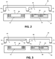
- FIGS. 2-6 A portion of a process of fabricating MEMS devices that utilizes expandable polymer microspheres is depicted in FIGS. 2-6 .
- the MEMS devices 30, 32 are provided on a silicon chip or wafer 34.
- the wafer 34 is depicted after undergoing processes to form semiconductor components, including the MEMS devices 30, 32, thereon, and after being capped with a cap wafer 36, e.g., polysilicon, to encapsulate the components on the wafer 34.
- the semiconductor components comprise a MEMS accelerometer 30 and a MEMS gyroscope 32.
- a plurality of MEMS accelerometers and a plurality of MEMS gyroscopes may be provided on the wafer.
- other types of MEMS devices may be provided on the wafer in addition to or as an alternative to the devices depicted in FIGS. 2-6 .
- the MEMS accelerometer 30 and the MEMS gyroscope 32 each include a thin membrane 38, 40 that is provided over a cavity 42, 44 formed in the wafer 34.
- the cap wafer 36 includes recesses 46, 48 which encapsulate the MEMS devices when the cap wafer 36 is placed on the wafer.
- the cap wafer 36 includes walls 50 which form barriers between and around the MEMS devices 30, 32 on the wafer 34.
- the barrier walls 50 of the cap wafer 36 are bonded to the wafer 34 using a suitable bonding material/process 52.
- an expandable material 54 such as expandable polymer microspheres
- any recesses which are to encapsulate the devices which require a high pressure level within the sealed cavity, which in this case, includes the MEMS accelerometer 30.
- the expandable material 54 is deposited into the recess 46 for the MEMS accelerometer 30.
- the expandable material 54 may be deposited in any suitable manner, such as screen printing, and may undergo further processing, such as patterning, to achieve the desired formation of expandable material within the recess. Note that during wafer-scale bonding, the pressure level may reach as low as 5e-7 bar (or even lower) before bonding commences so the process used to deposit the microspheres will have to be compatible with pressures approaching vacuum.
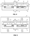
- the wafer bonding is performed by bringing the two wafers 34, 36 into contact within a bonding chamber 58 and applying a bonding force using a clamping device 56, such as a piston or other type of mechanism.
- the bonding force is applied to correct for any wafer stress/warp and bring the wafers uniformly and firmly into contact with each other.
- the temperature is increased, as depicted in FIG. 5 , to a bonding temperature which depends on the type of bonding material/processes used.
- the bonding temperature would be the eutectic temperature in case of a eutectic bonding.
- the bonding temperature is well above the activation temperatures of the expandable microspheres.
- expansion of the microspheres occurs within the sealed cavity of the MEMS accelerometer in parallel with the bonding process.
- Typical polymer microspheres have an activation temperature of 90 °C to 160 °C. Since typical bond temperatures are above 300-400 °C, the bond force should be applied and the wafers should be brought firmly into contact with each other before applying the bond temperature so the expansion of the polymer microspheres (and subsequent reduction of entrapped volume) happens within the recesses of the cap wafer.
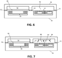
- the volume of the sealed cavity 46 for the accelerometer 30 (in this case) is considerably smaller than the volume of the sealed cavity 48 of the gyroscope 32 due to the expansion of the polymer microspheres 54, as can be seen in FIGS. 5 and 6 .
- the reduction in volume of the sealed cavity 46 enables the sealed in pressure level for the MEMS accelerometer 30 to be orders of magnitude higher than the pressure level in the other recess 48 which, in this case, encapsulates the gyroscope 32.
- the sealed in pressure for the MEMS accelerometer 30 in the recess 46 may be as high as 10 ⁇ 100 mbar while the sealed in pressure in the recess 48 for the MEMS gyroscope 32 may be about 10-100 ⁇ bar.
- the amount of desired volume reduction may be achieved by selecting the microspheres which exhibit the desired level of expansion and have an activation temperature which is lower than the bonding temperature to be utilized.
- partially expanded microspheres can also be used in addition to carefully planning the area of application within the recesses of the cap wafer.
- the bonding chamber 58 By combining the use of expandable microspheres and getters in a fabrication process, less stringent pressure requirements can be utilized within the bonding chamber because the use of both expandable microspheres and getters widens the range of pressure levels that may be achieved from a given vacuum level sealed within a cavity. For example, when only a getter is used, the chamber 58 would need to be pumped down to the pressure that is required to seal-in the accelerometer cavity (e.g., 10-100 mbar) while the rest of lowering of pressure in the gyroscope cavity (e.g., to 10-100 ⁇ bar) has to be effected using the getter.
- the accelerometer cavity e.g., 10-100 mbar
- the rest of lowering of pressure in the gyroscope cavity e.g., to 10-100 ⁇ bar
- the chamber 58 When expandable microspheres are used alone, the chamber 58 would need to be pumped down to a very low vacuum level ( ⁇ 10 ⁇ bar) and although this could seal-in the desired vacuum in the gyroscope cavity, the accelerometer cavity would have to rely purely on the expandable microspheres to bring up the sealed-in pressure by two to three orders of magnitude. If the cavity dimensions were not sufficiently large, such a wide range of pressure variation might not be possible using just the microspheres.
- FIG. 7 depicts an embodiment in which an expandable material is used for volume reduction and increasing pressure in a first recess for a first MEMS device and a getter material is used for decreasing pressure in a second recess for a second MEMS device.
- the first MEMS device 30 comprises a MEMS accelerometer and the second MEMS device 32 comprises a MEMS gyroscope.
- An expandable material 54 such as polymer microspheres, is deposited into the recess 46 for the first MEMS device 30, which has a higher pressure specification than the second MEMS device 32.
- the getter material 60 is deposited into the recess 48 for the second MEMS device.
- the cap wafer 36 is then bonded to the MEMS wafer 34, e.g., through the application of pressure and heat, to seal a first volume within the first recess 46 and a second volume within the second recess 48.
- the expansion of the expandable material occurs which reduces the first volume within the first recess after the first recess has been sealed and causes in increase in pressure within the first recess by one/two orders of magnitude to approximately 10-100 mbar.
- the getter absorbs air molecules which causes a reduction in pressure within the second recess by one/two orders of magnitude to approximately 10-100 ⁇ bar.
- the chamber 58 could be pumped down to a more reasonable value, e.g., 1 mBAR, than would otherwise be possible.
- a post-bonding process may be used to activate the expansion of the microspheres.
- the bonding could therefore be carried out at much lower temperature which allows low temperature bonding processes, such as Silicon direct bond or other low temperature eutectic or intermetallic phase bonds, to be used.
- a post-bond heating process may be used to heat the microspheres to the activation temperature.
- an infrared laser 62 may be used to locally heat the microspheres to expand the microspheres in targeted zones.
Landscapes
- Engineering & Computer Science (AREA)
- Microelectronics & Electronic Packaging (AREA)
- Manufacturing & Machinery (AREA)
- Computer Hardware Design (AREA)
- Micromachines (AREA)
Claims (19)
- Procédé de fabrication d'un dispositif de système microélectromécanique (MEMS) consistant :à déposer un matériau expansible dans un premier évidement d'une tranche de couverture, la tranche de couverture comprenant une pluralité de parois qui entourent et délimitent le premier évidement et un second évidement, le matériau expansible n'étant pas déposé dans le second évidement, la pluralité de parois comprenant au moins une paroi de séparation qui sépare le premier évidement du second évidement, le matériau expansible ayant une température d'activation à laquelle le matériau expansible se dilate ;à lier la tranche de couverture sur une tranche MEMS, la tranche MEMS comprenant un premier dispositif MEMS et un second dispositif MEMS qui sont intégrés dans la même tranche MEMS, la pluralité de parois de la tranche de couverture étant liées à la tranche MEMS de telle sorte que le premier dispositif MEMS soit encapsulé dans le premier évidement et que le second dispositif MEMS soit encapsulé dans le second évidement, la liaison ayant pour résultat un premier volume qui est tenu de façon étanche à l'intérieur du premier évidement et un second volume qui est tenu de façon étanche à l'intérieur du second évidement, le premier volume étant tenu de façon étanche à un premier niveau de pression et le second volume étant tenu de façon étanche à un second niveau de pression ; età chauffer le matériau expansible à la température d'activation de telle sorte que le matériau expansible se dilate à l'intérieur du premier évidement.
- Procédé selon la revendication 1, dans lequel la dilatation du matériau expansible réduit le premier volume à l'intérieur du premier évidement, la réduction du premier volume ayant pour résultat une augmentation du premier niveau de pression.
- Procédé selon la revendication 1, dans lequel le premier dispositif MEMS comprend un accéléromètre MEMS.
- Procédé selon la revendication 3, dans lequel le second dispositif MEMS comprend un gyroscope MEMS.
- Procédé selon la revendication 1, dans lequel le matériau expansible comprend des microsphères de polymère.
- Procédé selon la revendication 1, dans lequel le chauffage local est effectué à l'aide d'un laser infrarouge.
- Procédé selon la revendication 1, dans lequel la liaison consiste
à presser la tranche de couverture sur la tranche MEMS ; dans lequel les premier et second niveaux de pression sont sensiblement égaux lorsque la tranche de couverture est pressée sur la tranche MEMS ; et
dans lequel la tranche de couverture et la tranche MEMS sont chauffées avec la tranche de couverture pressée sur la tranche MRMS à une température de liaison, la température de liaison amenant la pluralité de parois de la tranche de couverture à se lier à une tranche MEMS de telle sorte que le premier volume soit tenu de façon étanche à l'intérieur du premier évidement et que le second volume soit tenu de façon étanche à l'intérieur du second évidement et dans lequel la température de liaison est supérieure à la température d'activation de telle sorte que le matériau expansible se dilate à l'intérieur du premier évidement après que le premier volume est tenu de façon étanche à l'intérieur du premier évidement. - Procédé selon la revendication 7, dans lequel la dilatation du matériau expansible réduit le premier volume à l'intérieur du premier évidement, la réduction du premier volume augmentant le premier niveau de pression de telle sorte que le premier niveau de pression soit supérieur au second niveau de pression.
- Procédé selon la revendication 8, dans lequel, après la dilatation du matériau expansible, le premier niveau de pression tenu de façon étanche à l'intérieur du premier évidement est entre approximativement 10 mbars et approximativement 100 mbars et le second niveau de pression tenu de façon étanche à l'intérieur du second évidement est entre approximativement 10 µbars et approximativement 100 µbars.
- Procédé selon la revendication 7, dans lequel le premier dispositif MEMS comprend un accéléromètre MEMS.
- Procédé selon la revendication 10, dans lequel le second dispositif MEMS comprend un gyroscope MEMS.
- Procédé selon la revendication 7, dans lequel le matériau expansible comprend des microsphères de polymère.
- Procédé selon la revendication 7, dans lequel la température de liaison a pour résultat une liaison eutectique entre les parois de la tranche de couverture et la tranche MEMS.
- Procédé selon la revendication 7, dans lequel la température de liaison est égale ou supérieure à 300 °C.
- Procédé selon la revendication 14, dans lequel la température d'activation est comprise entre approximativement 90 °C et approximativement 160 °C.
- Procédé selon la revendication 7, dans lequel la pression de la tranche de couverture sur la tranche MEMS consiste à serrer la tranche de couverture et la tranche MEMS ensemble avec une force de liaison à l'aide d'un dispositif de serrage, et
dans lequel le chauffage de la tranche de couverture et de la tranche MEMS consiste à chauffer la tranche de couverture et la tranche MEMS pendant que la force de liaison est appliquée à la tranche de couverture et à la tranche MEMS. - Procédé selon la revendication 7, consistant en outre :
à déposer un dégazeur dans le second évidement avant de presser la tranche de couverture sur la tranche MEMS, le dégazeur provoquant une baisse du second niveau de pression dans le second évidement après que le second volume a été tenu de façon étanche à l'intérieur du second évidement. - Dispositif de système microélectromécanique (MEMS) comprenant :une tranche MEMS comprenant un premier dispositif MEMS et un second dispositif MEMS ;une tranche de couverture liée à la tranche MEMS, la tranche de couverture comprenant un premier évidement qui encapsule le premier dispositif MEMS et un second évidement qui encapsule le second dispositif MEMS, un premier volume qui est tenu de façon étanche dans le premier évidement et un second volume qui est tenu de façon étanche dans le second évidement ; et caractérisé pardes microsphères de polymère expansibles tenues de façon étanche à l'intérieur du premier évidement, les microsphères de polymère ayant été chauffées à une température d'activation pour provoquer la dilatation des microsphères de polymère.
- Dispositif MEMS selon la revendication 18, dans lequel le premier dispositif MEMS est un accéléromètre et le second dispositif MEMS est un gyroscope.
Applications Claiming Priority (2)
| Application Number | Priority Date | Filing Date | Title |
|---|---|---|---|
| US201462089898P | 2014-12-10 | 2014-12-10 | |
| PCT/US2015/065061 WO2016094700A1 (fr) | 2014-12-10 | 2015-12-10 | Anti-dégazeur : microsphères polymères dilatables pour dispositifs mems |
Publications (3)
| Publication Number | Publication Date |
|---|---|
| EP3230200A1 EP3230200A1 (fr) | 2017-10-18 |
| EP3230200A4 EP3230200A4 (fr) | 2018-07-04 |
| EP3230200B1 true EP3230200B1 (fr) | 2020-02-12 |
Family
ID=56108206
Family Applications (1)
| Application Number | Title | Priority Date | Filing Date |
|---|---|---|---|
| EP15866598.4A Active EP3230200B1 (fr) | 2014-12-10 | 2015-12-10 | Anti-dégazeur : microsphères polymères dilatables pour dispositifs mems |
Country Status (3)
| Country | Link |
|---|---|
| US (1) | US10035699B2 (fr) |
| EP (1) | EP3230200B1 (fr) |
| WO (1) | WO2016094700A1 (fr) |
Families Citing this family (1)
| Publication number | Priority date | Publication date | Assignee | Title |
|---|---|---|---|---|
| CN115092876A (zh) * | 2022-05-23 | 2022-09-23 | 美新半导体(天津)有限公司 | 带腔体器件的气密封装结构 |
Family Cites Families (8)
| Publication number | Priority date | Publication date | Assignee | Title |
|---|---|---|---|---|
| US4661302A (en) * | 1986-04-07 | 1987-04-28 | The Dow Chemical Company | Expandable polymeric composition and method |
| US5689089A (en) * | 1996-09-20 | 1997-11-18 | Motorola, Inc. | Electronic control module having fluid-tight seals of a polymer material which expands when wet |
| US6099948A (en) * | 1997-05-08 | 2000-08-08 | Henkel Corporation | Encapsulation of pre-expanded elastomeric foam with a thermoplastic |
| US7047633B2 (en) * | 2003-05-23 | 2006-05-23 | National Starch And Chemical Investment Holding, Corporation | Method of using pre-applied underfill encapsulant |
| US7981849B2 (en) | 2007-03-08 | 2011-07-19 | International Business Machines Corporation | Reversible thermal thickening grease |
| JP5298047B2 (ja) | 2010-02-26 | 2013-09-25 | 日立オートモティブシステムズ株式会社 | 複合センサの製造方法 |
| US20140225206A1 (en) * | 2013-02-11 | 2014-08-14 | Yizhen Lin | Pressure level adjustment in a cavity of a semiconductor die |
| US9352956B2 (en) * | 2014-01-16 | 2016-05-31 | Taiwan Semiconductor Manufacturing Company, Ltd. | MEMS devices and methods for forming same |
-
2015
- 2015-12-10 EP EP15866598.4A patent/EP3230200B1/fr active Active
- 2015-12-10 WO PCT/US2015/065061 patent/WO2016094700A1/fr not_active Ceased
- 2015-12-10 US US15/534,477 patent/US10035699B2/en active Active
Non-Patent Citations (1)
| Title |
|---|
| None * |
Also Published As
| Publication number | Publication date |
|---|---|
| WO2016094700A1 (fr) | 2016-06-16 |
| EP3230200A4 (fr) | 2018-07-04 |
| US20170362078A1 (en) | 2017-12-21 |
| EP3230200A1 (fr) | 2017-10-18 |
| US10035699B2 (en) | 2018-07-31 |
Similar Documents
| Publication | Publication Date | Title |
|---|---|---|
| US9718679B2 (en) | Integrated heater for gettering or outgassing activation | |
| US10384932B2 (en) | Device including micromechanical components in cavities having different pressures and method for its manufacture | |
| TWI607959B (zh) | 包括不同受控壓力下的多個空腔之cmos-mems集成裝置及製造方法 | |
| US20140225206A1 (en) | Pressure level adjustment in a cavity of a semiconductor die | |
| JP2008524008A (ja) | Mems慣性センサ用射出成形パッケージ | |
| CN101898746B (zh) | 要求不同气氛压力的mems器件圆片级集成封装方法 | |
| US9650241B2 (en) | Method for providing a MEMS device with a plurality of sealed enclosures having uneven standoff structures and MEMS device thereof | |
| JP2007144617A (ja) | Mems装置パッケージング方法 | |
| CN105129727B (zh) | 具有两个半导体构件的部件和用于制造两个半导体构件之间的键合连接的方法 | |
| CN104163396B (zh) | 通过可透材料注入惰性气体封装微电子装置的方法 | |
| US9511998B2 (en) | MEMS device having a getter | |
| US9416003B2 (en) | Semiconductor die with high pressure cavity | |
| US7288464B2 (en) | MEMS packaging structure and methods | |
| US20060234412A1 (en) | MEMS release methods | |
| US20160137487A1 (en) | Package structure including a cavity coupled to an injection gas channel composed of a permeable material | |
| KR20180090853A (ko) | 레이저 활성화 게터 물질을 포함하는 센서 요소 | |
| US10035699B2 (en) | Anti-getter: expandable polymer microspheres for MEMS devices | |
| US10029911B2 (en) | Micromechanical component including a diffusion stop channel | |
| US9637372B2 (en) | Bonded wafer structure having cavities with low pressure and method for forming | |
| CN102556944A (zh) | Mems装置的制作方法 | |
| CN109311661B (zh) | 用于晶片的共晶键合的方法和晶片复合体 | |
| Cho et al. | An on-chip hermetic packaging technology for micromechanical devices | |
| Merz et al. | Combined MEMS inertial sensors for IMU applications | |
| Antelius et al. | Wafer-level vacuum sealing by coining of wire bonded gold bumps | |
| JP2006500233A (ja) | マイクロマシニング型の構成素子および方法 |
Legal Events
| Date | Code | Title | Description |
|---|---|---|---|
| STAA | Information on the status of an ep patent application or granted ep patent |
Free format text: STATUS: THE INTERNATIONAL PUBLICATION HAS BEEN MADE |
|
| PUAI | Public reference made under article 153(3) epc to a published international application that has entered the european phase |
Free format text: ORIGINAL CODE: 0009012 |
|
| STAA | Information on the status of an ep patent application or granted ep patent |
Free format text: STATUS: REQUEST FOR EXAMINATION WAS MADE |
|
| 17P | Request for examination filed |
Effective date: 20170710 |
|
| AK | Designated contracting states |
Kind code of ref document: A1 Designated state(s): AL AT BE BG CH CY CZ DE DK EE ES FI FR GB GR HR HU IE IS IT LI LT LU LV MC MK MT NL NO PL PT RO RS SE SI SK SM TR |
|
| AX | Request for extension of the european patent |
Extension state: BA ME |
|
| DAV | Request for validation of the european patent (deleted) | ||
| DAX | Request for extension of the european patent (deleted) | ||
| A4 | Supplementary search report drawn up and despatched |
Effective date: 20180606 |
|
| RIC1 | Information provided on ipc code assigned before grant |
Ipc: B81C 3/00 20060101ALI20180530BHEP Ipc: B81B 7/02 20060101AFI20180530BHEP Ipc: B81C 1/00 20060101ALI20180530BHEP |
|
| GRAP | Despatch of communication of intention to grant a patent |
Free format text: ORIGINAL CODE: EPIDOSNIGR1 |
|
| STAA | Information on the status of an ep patent application or granted ep patent |
Free format text: STATUS: GRANT OF PATENT IS INTENDED |
|
| INTG | Intention to grant announced |
Effective date: 20190321 |
|
| GRAJ | Information related to disapproval of communication of intention to grant by the applicant or resumption of examination proceedings by the epo deleted |
Free format text: ORIGINAL CODE: EPIDOSDIGR1 |
|
| STAA | Information on the status of an ep patent application or granted ep patent |
Free format text: STATUS: REQUEST FOR EXAMINATION WAS MADE |
|
| INTC | Intention to grant announced (deleted) | ||
| GRAP | Despatch of communication of intention to grant a patent |
Free format text: ORIGINAL CODE: EPIDOSNIGR1 |
|
| STAA | Information on the status of an ep patent application or granted ep patent |
Free format text: STATUS: GRANT OF PATENT IS INTENDED |
|
| INTG | Intention to grant announced |
Effective date: 20191004 |
|
| GRAS | Grant fee paid |
Free format text: ORIGINAL CODE: EPIDOSNIGR3 |
|
| GRAA | (expected) grant |
Free format text: ORIGINAL CODE: 0009210 |
|
| STAA | Information on the status of an ep patent application or granted ep patent |
Free format text: STATUS: THE PATENT HAS BEEN GRANTED |
|
| AK | Designated contracting states |
Kind code of ref document: B1 Designated state(s): AL AT BE BG CH CY CZ DE DK EE ES FI FR GB GR HR HU IE IS IT LI LT LU LV MC MK MT NL NO PL PT RO RS SE SI SK SM TR |
|
| REG | Reference to a national code |
Ref country code: GB Ref legal event code: FG4D |
|
| REG | Reference to a national code |
Ref country code: CH Ref legal event code: EP |
|
| REG | Reference to a national code |
Ref country code: AT Ref legal event code: REF Ref document number: 1231855 Country of ref document: AT Kind code of ref document: T Effective date: 20200215 |
|
| REG | Reference to a national code |
Ref country code: IE Ref legal event code: FG4D |
|
| REG | Reference to a national code |
Ref country code: DE Ref legal event code: R096 Ref document number: 602015047072 Country of ref document: DE |
|
| RAP2 | Party data changed (patent owner data changed or rights of a patent transferred) |
Owner name: ROBERT BOSCH GMBH |
|
| PG25 | Lapsed in a contracting state [announced via postgrant information from national office to epo] |
Ref country code: RS Free format text: LAPSE BECAUSE OF FAILURE TO SUBMIT A TRANSLATION OF THE DESCRIPTION OR TO PAY THE FEE WITHIN THE PRESCRIBED TIME-LIMIT Effective date: 20200212 Ref country code: NO Free format text: LAPSE BECAUSE OF FAILURE TO SUBMIT A TRANSLATION OF THE DESCRIPTION OR TO PAY THE FEE WITHIN THE PRESCRIBED TIME-LIMIT Effective date: 20200512 Ref country code: FI Free format text: LAPSE BECAUSE OF FAILURE TO SUBMIT A TRANSLATION OF THE DESCRIPTION OR TO PAY THE FEE WITHIN THE PRESCRIBED TIME-LIMIT Effective date: 20200212 |
|
| REG | Reference to a national code |
Ref country code: LT Ref legal event code: MG4D |
|
| REG | Reference to a national code |
Ref country code: NL Ref legal event code: MP Effective date: 20200212 |
|
| PG25 | Lapsed in a contracting state [announced via postgrant information from national office to epo] |
Ref country code: SE Free format text: LAPSE BECAUSE OF FAILURE TO SUBMIT A TRANSLATION OF THE DESCRIPTION OR TO PAY THE FEE WITHIN THE PRESCRIBED TIME-LIMIT Effective date: 20200212 Ref country code: IS Free format text: LAPSE BECAUSE OF FAILURE TO SUBMIT A TRANSLATION OF THE DESCRIPTION OR TO PAY THE FEE WITHIN THE PRESCRIBED TIME-LIMIT Effective date: 20200612 Ref country code: LV Free format text: LAPSE BECAUSE OF FAILURE TO SUBMIT A TRANSLATION OF THE DESCRIPTION OR TO PAY THE FEE WITHIN THE PRESCRIBED TIME-LIMIT Effective date: 20200212 Ref country code: HR Free format text: LAPSE BECAUSE OF FAILURE TO SUBMIT A TRANSLATION OF THE DESCRIPTION OR TO PAY THE FEE WITHIN THE PRESCRIBED TIME-LIMIT Effective date: 20200212 Ref country code: GR Free format text: LAPSE BECAUSE OF FAILURE TO SUBMIT A TRANSLATION OF THE DESCRIPTION OR TO PAY THE FEE WITHIN THE PRESCRIBED TIME-LIMIT Effective date: 20200513 Ref country code: BG Free format text: LAPSE BECAUSE OF FAILURE TO SUBMIT A TRANSLATION OF THE DESCRIPTION OR TO PAY THE FEE WITHIN THE PRESCRIBED TIME-LIMIT Effective date: 20200512 |
|
| PG25 | Lapsed in a contracting state [announced via postgrant information from national office to epo] |
Ref country code: NL Free format text: LAPSE BECAUSE OF FAILURE TO SUBMIT A TRANSLATION OF THE DESCRIPTION OR TO PAY THE FEE WITHIN THE PRESCRIBED TIME-LIMIT Effective date: 20200212 |
|
| PG25 | Lapsed in a contracting state [announced via postgrant information from national office to epo] |
Ref country code: EE Free format text: LAPSE BECAUSE OF FAILURE TO SUBMIT A TRANSLATION OF THE DESCRIPTION OR TO PAY THE FEE WITHIN THE PRESCRIBED TIME-LIMIT Effective date: 20200212 Ref country code: SM Free format text: LAPSE BECAUSE OF FAILURE TO SUBMIT A TRANSLATION OF THE DESCRIPTION OR TO PAY THE FEE WITHIN THE PRESCRIBED TIME-LIMIT Effective date: 20200212 Ref country code: DK Free format text: LAPSE BECAUSE OF FAILURE TO SUBMIT A TRANSLATION OF THE DESCRIPTION OR TO PAY THE FEE WITHIN THE PRESCRIBED TIME-LIMIT Effective date: 20200212 Ref country code: RO Free format text: LAPSE BECAUSE OF FAILURE TO SUBMIT A TRANSLATION OF THE DESCRIPTION OR TO PAY THE FEE WITHIN THE PRESCRIBED TIME-LIMIT Effective date: 20200212 Ref country code: SK Free format text: LAPSE BECAUSE OF FAILURE TO SUBMIT A TRANSLATION OF THE DESCRIPTION OR TO PAY THE FEE WITHIN THE PRESCRIBED TIME-LIMIT Effective date: 20200212 Ref country code: PT Free format text: LAPSE BECAUSE OF FAILURE TO SUBMIT A TRANSLATION OF THE DESCRIPTION OR TO PAY THE FEE WITHIN THE PRESCRIBED TIME-LIMIT Effective date: 20200705 Ref country code: LT Free format text: LAPSE BECAUSE OF FAILURE TO SUBMIT A TRANSLATION OF THE DESCRIPTION OR TO PAY THE FEE WITHIN THE PRESCRIBED TIME-LIMIT Effective date: 20200212 Ref country code: CZ Free format text: LAPSE BECAUSE OF FAILURE TO SUBMIT A TRANSLATION OF THE DESCRIPTION OR TO PAY THE FEE WITHIN THE PRESCRIBED TIME-LIMIT Effective date: 20200212 Ref country code: ES Free format text: LAPSE BECAUSE OF FAILURE TO SUBMIT A TRANSLATION OF THE DESCRIPTION OR TO PAY THE FEE WITHIN THE PRESCRIBED TIME-LIMIT Effective date: 20200212 |
|
| REG | Reference to a national code |
Ref country code: DE Ref legal event code: R097 Ref document number: 602015047072 Country of ref document: DE |
|
| REG | Reference to a national code |
Ref country code: AT Ref legal event code: MK05 Ref document number: 1231855 Country of ref document: AT Kind code of ref document: T Effective date: 20200212 |
|
| PLBE | No opposition filed within time limit |
Free format text: ORIGINAL CODE: 0009261 |
|
| STAA | Information on the status of an ep patent application or granted ep patent |
Free format text: STATUS: NO OPPOSITION FILED WITHIN TIME LIMIT |
|
| 26N | No opposition filed |
Effective date: 20201113 |
|
| PG25 | Lapsed in a contracting state [announced via postgrant information from national office to epo] |
Ref country code: AT Free format text: LAPSE BECAUSE OF FAILURE TO SUBMIT A TRANSLATION OF THE DESCRIPTION OR TO PAY THE FEE WITHIN THE PRESCRIBED TIME-LIMIT Effective date: 20200212 Ref country code: IT Free format text: LAPSE BECAUSE OF FAILURE TO SUBMIT A TRANSLATION OF THE DESCRIPTION OR TO PAY THE FEE WITHIN THE PRESCRIBED TIME-LIMIT Effective date: 20200212 |
|
| PG25 | Lapsed in a contracting state [announced via postgrant information from national office to epo] |
Ref country code: SI Free format text: LAPSE BECAUSE OF FAILURE TO SUBMIT A TRANSLATION OF THE DESCRIPTION OR TO PAY THE FEE WITHIN THE PRESCRIBED TIME-LIMIT Effective date: 20200212 Ref country code: PL Free format text: LAPSE BECAUSE OF FAILURE TO SUBMIT A TRANSLATION OF THE DESCRIPTION OR TO PAY THE FEE WITHIN THE PRESCRIBED TIME-LIMIT Effective date: 20200212 |
|
| REG | Reference to a national code |
Ref country code: CH Ref legal event code: PL |
|
| PG25 | Lapsed in a contracting state [announced via postgrant information from national office to epo] |
Ref country code: MC Free format text: LAPSE BECAUSE OF FAILURE TO SUBMIT A TRANSLATION OF THE DESCRIPTION OR TO PAY THE FEE WITHIN THE PRESCRIBED TIME-LIMIT Effective date: 20200212 |
|
| REG | Reference to a national code |
Ref country code: BE Ref legal event code: MM Effective date: 20201231 |
|
| PG25 | Lapsed in a contracting state [announced via postgrant information from national office to epo] |
Ref country code: IE Free format text: LAPSE BECAUSE OF NON-PAYMENT OF DUE FEES Effective date: 20201210 Ref country code: LU Free format text: LAPSE BECAUSE OF NON-PAYMENT OF DUE FEES Effective date: 20201210 |
|
| PG25 | Lapsed in a contracting state [announced via postgrant information from national office to epo] |
Ref country code: LI Free format text: LAPSE BECAUSE OF NON-PAYMENT OF DUE FEES Effective date: 20201231 Ref country code: CH Free format text: LAPSE BECAUSE OF NON-PAYMENT OF DUE FEES Effective date: 20201231 |
|
| PG25 | Lapsed in a contracting state [announced via postgrant information from national office to epo] |
Ref country code: TR Free format text: LAPSE BECAUSE OF FAILURE TO SUBMIT A TRANSLATION OF THE DESCRIPTION OR TO PAY THE FEE WITHIN THE PRESCRIBED TIME-LIMIT Effective date: 20200212 Ref country code: MT Free format text: LAPSE BECAUSE OF FAILURE TO SUBMIT A TRANSLATION OF THE DESCRIPTION OR TO PAY THE FEE WITHIN THE PRESCRIBED TIME-LIMIT Effective date: 20200212 Ref country code: CY Free format text: LAPSE BECAUSE OF FAILURE TO SUBMIT A TRANSLATION OF THE DESCRIPTION OR TO PAY THE FEE WITHIN THE PRESCRIBED TIME-LIMIT Effective date: 20200212 |
|
| PG25 | Lapsed in a contracting state [announced via postgrant information from national office to epo] |
Ref country code: MK Free format text: LAPSE BECAUSE OF FAILURE TO SUBMIT A TRANSLATION OF THE DESCRIPTION OR TO PAY THE FEE WITHIN THE PRESCRIBED TIME-LIMIT Effective date: 20200212 Ref country code: AL Free format text: LAPSE BECAUSE OF FAILURE TO SUBMIT A TRANSLATION OF THE DESCRIPTION OR TO PAY THE FEE WITHIN THE PRESCRIBED TIME-LIMIT Effective date: 20200212 |
|
| PG25 | Lapsed in a contracting state [announced via postgrant information from national office to epo] |
Ref country code: BE Free format text: LAPSE BECAUSE OF NON-PAYMENT OF DUE FEES Effective date: 20201231 |
|
| PGFP | Annual fee paid to national office [announced via postgrant information from national office to epo] |
Ref country code: GB Payment date: 20231220 Year of fee payment: 9 |
|
| PGFP | Annual fee paid to national office [announced via postgrant information from national office to epo] |
Ref country code: FR Payment date: 20231219 Year of fee payment: 9 |
|
| PGFP | Annual fee paid to national office [announced via postgrant information from national office to epo] |
Ref country code: DE Payment date: 20240227 Year of fee payment: 9 |
|
| REG | Reference to a national code |
Ref country code: DE Ref legal event code: R119 Ref document number: 602015047072 Country of ref document: DE |
|
| GBPC | Gb: european patent ceased through non-payment of renewal fee |
Effective date: 20241210 |
|
| PG25 | Lapsed in a contracting state [announced via postgrant information from national office to epo] |
Ref country code: DE Free format text: LAPSE BECAUSE OF NON-PAYMENT OF DUE FEES Effective date: 20250701 |
|
| PG25 | Lapsed in a contracting state [announced via postgrant information from national office to epo] |
Ref country code: GB Free format text: LAPSE BECAUSE OF NON-PAYMENT OF DUE FEES Effective date: 20241210 |
|
| PG25 | Lapsed in a contracting state [announced via postgrant information from national office to epo] |
Ref country code: FR Free format text: LAPSE BECAUSE OF NON-PAYMENT OF DUE FEES Effective date: 20241231 |