EP3230525B1 - Appareil de formation de bouteilles d'urinoir en fibres moulées - Google Patents
Appareil de formation de bouteilles d'urinoir en fibres moulées Download PDFInfo
- Publication number
- EP3230525B1 EP3230525B1 EP15816831.0A EP15816831A EP3230525B1 EP 3230525 B1 EP3230525 B1 EP 3230525B1 EP 15816831 A EP15816831 A EP 15816831A EP 3230525 B1 EP3230525 B1 EP 3230525B1
- Authority
- EP
- European Patent Office
- Prior art keywords
- mould
- tools
- tool
- vacuum
- bottle
- Prior art date
- Legal status (The legal status is an assumption and is not a legal conclusion. Google has not performed a legal analysis and makes no representation as to the accuracy of the status listed.)
- Active
Links
Images




Classifications
-
- D—TEXTILES; PAPER
- D21—PAPER-MAKING; PRODUCTION OF CELLULOSE
- D21J—FIBREBOARD; MANUFACTURE OF ARTICLES FROM CELLULOSIC FIBROUS SUSPENSIONS OR FROM PAPIER-MACHE
- D21J3/00—Manufacture of articles by pressing wet fibre pulp, or papier-mâché, between moulds
- D21J3/10—Manufacture of articles by pressing wet fibre pulp, or papier-mâché, between moulds of hollow bodies
-
- D—TEXTILES; PAPER
- D21—PAPER-MAKING; PRODUCTION OF CELLULOSE
- D21J—FIBREBOARD; MANUFACTURE OF ARTICLES FROM CELLULOSIC FIBROUS SUSPENSIONS OR FROM PAPIER-MACHE
- D21J7/00—Manufacture of hollow articles from fibre suspensions or papier-mâché by deposition of fibres in or on a wire-net mould
Definitions
- the present invention relates to an apparatus for forming moulded fibre urinal bottles, and to urinal bottles formed using said apparatus.
- Single use urinal bottles formed from moulded paper pulp are a standard means for assisting incontinent and bed ridden patients with their urination needs in the UK.
- the pulp urinal bottles are administered to patients for use while in bed. Following use the pulp material allows the urinal bottles to be disposed of in a macerator.
- Single use urinal bottles are known to reduce the incidence of healthcare associated infections (HCAI).
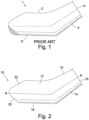
- Figure 1 shows a typical pulp urinal bottle of the prior art.
- the urinal bottle 1 includes a hollow body 2 having a neck 4 extending to a circular opening 6.
- the bottle 1 includes a flat base 8 which supports the urinal bottle 1 when placed on a surface.
- the neck 4 is angled upwardly away from the base 8 to orient the opening 6 at a suitable location for use in bed while the base is supported on the surface of the bed. To ensure the urinal bottle 1 is water tight it is moulded as single piece item.
- European patent number EP1104822 describes a split mould tool with an inner surface and an outer surface.
- a vacuum cavity surrounds the outer surface of the mould tool.
- a pulp article is formed against the inner surface of the mould tool.
- a vacuum is applied to the vacuum cavity via an inlet at the base of the vacuum cavity and liquid from the wet pulp is drawn into the vacuum cavity via drainage channels in the mould tool.
- a standard pulp bottle mould comprises a split mould including a pair of independent mould tools, and liquid extraction and forming of the pulp is achieved by independently supplying a vacuum to both mould tools.
- a pulp moulding apparatus comprising first and second mould tools.
- the mould tools are movable between a closed configuration in which the first and second mould cavities combine to form a moulded pulp item and a release configuration in which the first and second mould tools are separated to enable release of the moulded pulp item.
- a vacuum source is connected to the first mould tool.
- the first and second mould tools include a fluid connection arrangement that fluidly connects the first and second mould tools when they are in the closed configuration such that the vacuum applied to the first mould tool is simultaneously applied to the second mould tool.
- separate vacuum sources are connected to both mould tools.
- the first mould tool preferably includes a mould surface having a porous first mould cavity formed therein for moulding a first portion of a moulded pulp item and the second mould tool includes a mould surface having a porous second mould cavity formed therein for moulding a second portion of the moulded pulp item.
- Each of the mould cavities includes an inner mould surface to which the pulp is formed and an opposing rear surface.
- the vacuum source is connected to the first mould tool such that it applies a vacuum to the rear surface of the first mould cavity
- the fluid connector arrangement is configured to fluidly connect the first and second mould tools such that the vacuum applied to the rear surface of the first mould tool is simultaneously applied to the rear surface of the second mould cavity via the fluid connector.
- the term vacuum chamber or vacuum cavity refers to any void, space or channel located behind the mould surface via which a vacuum may be applied to the rear surface of the mould cavity.
- the vacuum chamber is also a drainage chamber as liquid drawn from the mould surface by the vacuum is drawn into the vacuum chamber.
- the vacuum chamber may be a single continuous volume or a plurality of separate channels or voids.
- the first and second mould tools preferably each include a vacuum cavity located on the rear side of the mould surface, and the fluid connection arrangement fluidly connects the vacuum chambers.
- the first and second mould tools may each include a mould tool body, and the fluid connection arrangement includes first and second channels formed in the mould tool bodies of the first and second mould tools respectively, and a connector arranged to connect the first and second channels in a sealed manner when the mould tools are closed.
- the fluid connector may comprise a female connector element provided on one of the first and second mould tools and a male connector element provided on the other of the first and second mould tools, configured to be receive in the female connector element in a sealed manner to connect the first and second fluid channels.
- the mould surfaces of the first and second mould tools preferably face each other in the closed position and the female connector element extends into the mould surface of one of the first and second mould tools and the male connector element projects from the mould surface of the other of the first and second mould tools, the connector elements being arranged such that the male connector element is received in the female connector element when the mould tools are closed.
- the mould tools are preferably arranged such that in use the first mould tool is the lower mould tool and the second mould tool is the upper mould.
- the first and second mould tools preferably include one or more drainage channels formed therein which align when the mould tools are closed to allow liquid to drain from the upper vacuum chamber to the lower vacuum chamber.
- the rear side of the upper mould surface preferably includes raised regions arranged to channel liquid towards the fluid connector.
- the raised regions may located at the rear end of the mould surface. Alternatively or in addition the raised regions may be provided on the opposing sides of the mould cavities to the fluid connector.
- the raised regions are configured such that substantially all of the rear side of the mould surface is angled downwardly to the fluid connector.
- One or more drainage channels are preferably formed through the upper and lower mould tools to channel liquid from the upper vacuum chamber into the lower vacuum chamber.
- the mould comprising the upper and lower mould tools
- the angle of the drainage channels is such that they are oriented substantially vertically when the mould tools are mounted at the selected angle.
- the moulding apparatus preferably includes upper and lower mould platens including cavities arranged to receive the upper and lower mould tools respectively.
- the cavities of the mould platens are configured to support the mould tools at the selected forward angle.
- the mould platens include angled support surfaces configured to receive and support the base plates of the mould tools, the support surfaces being angled at the selected angle.
- the pulp moulding apparatus may comprises a rotational actuator arranged to rotate the mould tools when in the closed position to the selected angle.
- the mould tools are preferably configured to form a urinal bottle having a body and a neck extending from the body to an opening.
- the location of the bottle opening defines the front of the mould, and the fluid connector is located at the front end of the mould tools.
- a pulp moulding apparatus for moulding a urinal bottle has a main body and a neck extending from a front end of the main body to an opening.
- the apparatus comprises upper and lower mould tools movable between a closed configuration in which the first and second mould cavities combine to form a moulded pulp item and a release configuration in which the first and second mould tools are separated to enable release of the moulded pulp item.
- the lower mould tool includes a base plate and a mould cavity including a base section configured to form the base of the bottle and a rear wall section configured to form a rear wall portion of the bottle.
- the rear wall section is angled upwardly from the base section in a rearward direction at an angle of less than 90 degrees from the horizontal as defined by the plane of the base plate.
- the rear wall is angled upwardly from the base at an angle of 26 degrees.
- the angle of the rear wall section of the lower mould tool relative to the vertical as defined relative to the horizontal plane of the base plate is greater than the selected angle.
- the rear wall section of the lower mould tool is configured such that it is angled at 26 degrees to the base plate of the mould tool.
- the rear wall section of the lower mould tool is preferably configured such that it is angled rearwardly at 3 degrees to the vertical when the mould tool is supported in the mould platen at the 23 degrees forward angle, with the 3 degrees rearward angle forming a 3 degree positive draft allowing vertical removal of the bottle from the tool.
- the selected angle is preferably between 18 and 25 degrees. This is the angle at which the toolset sits on the base plate in degrees from horizontal. More preferably, the selected angle is 23 degrees.
- the selected forward angle allows excess pulp slurry to drain gravitationally from the bottle without overloading the vacuum system and the dewatering cycle of the formation of the pulp bottle. The range of angle effects the efficiency of the system. If the selected angle is too steep then the bottle may form too thinly or require a longer time in the pulp slurry to form completely as the flows out of the bottle under the action of gravity. Conversely if the angle is too shallow then the bottle may retain excess pulp slurry, which may cause softening of the lower neck of the bottle. Furthermore the bottom neck may deform when it is deposited on dryer conveyor.
- a pulp moulding apparatus for moulding a urinal bottle having a main body and a neck extending from a front end of the main body to an opening, the apparatus comprising upper and lower mould tools movable between a closed configuration in which the first and second mould cavities combine to form a moulded pulp item and a release configuration in which the first and second mould tools are separated to enable release of the moulded pulp item.
- An elongate lifting element is arranged to be inserted into the neck of the bottle, wherein the lifting element has an upper surface shaped to conform to the shape of the inner surface of the upper part of the bottle.
- the neck is preferably angled upwardly away from the upper edge of the main body of the bottle
- the lifting element includes a proximal body section having an upper edge shaped to support the upper inner surface of the neck, and a distal tip section that is angled upwardly away from the main body section at the same angle at which the neck of the bottle extends from the main body, such that the tip engages and supports a portion of the roof of the main body of the bottle while the main body section of the lifting element engages and supports the roof of the neck.
- a moulded pulp bottle having a main body and a neck extending from the main body to an opening, the method comprising:
- the mould includes upper and lower mould tools, each having base plates that are arranged parallel to each other.
- the moulding apparatus preferably includes upper and lower mould platens including cavities arranged to receive the upper and lower mould tools respectively. The cavities of the mould platens are angled to support the base plates of the mould tools at the selected forward angle.
- the mould is inserted into and removed from the vat vertically while angled forwardly at the selected angle.
- the upper and lower mould tools and are separated vertically while in the forwardly angled orientation with the upper tool being lifted away from the lower tool.
- the mould is preferably maintained in the forwardly angled arrangement for at least part of the dewatering stage.
- the bottle preferably comprises a base defining a horizontal plane of the bottle and the longitudinal axis of the neck is angled upwardly relative to the base.
- the downwardly angled position at which the mould tool is mounted is selected such that in said position the longitudinal axis of the neck of the bottle is substantially horizontal.
- the mould tool preferably comprises an upper mould tool and a lower mould tool and the method further comprises separating the mould tools after the dewatering phase and then vertically removing the bottle from the lower mould tool while the lower mould tool is maintained in the forwardly angled position.
- An elongate lifting element or 'finger' is preferably inserted into the opening of the bottle and then moved vertically to lift the bottle out of the lower mould tool.
- the lifting element is preferably inserted into the opening of the bottle before the mould tools are separated.
- the bottle is preferably moved to a conveyor by the lifting element, and the lifting element is rotated downwardly to cause the bottle to slide off the lifting element onto the conveyor.
- the lifting element is rotated downwardly an angle substantially equal to the selected forward angle of the mould tool such that the base of the bottle is substantially parallel with the conveyor.
- the lifting finger or spike rotates the bottle through 23 degrees to bring the base of the bottle horizontal to the conveyor. In this position the spike can retract out of the bottle to allow the bottle then to travel on the conveyor through the dryer.
- Movement of the conveyor is stopped while the bottle is deposited onto the conveyor.
- the bottle is placed on the conveyor facing in the forward direction, aligned with the direction of travel of the conveyor.
- the lifting finger is pointing in the opposing direction to the conveyor. Therefore, to allow retraction of the lifting finger the conveyor must be halted.
- the conveyor is synchronized with the spike position to stop at the time of drop off for a variable time as determined and programmed by the system controller.
- the period the conveyor is stopped is controlled to allow the lifting element to be retracted before movement of the conveyor restarts.
- pulp bottles are manufactured using a novel split tool arrangement, whereby two parts of the bottle, the upper half and lower half, are formed in independent moulding tools that come together into a closed position to form a bottle shape and are dipped into a pulp slurry.
- a vacuum is applied causing pulp fibres in the slurry to adhere to the gauze lining the moulding tools.
- the vacuum source is connected to the lower tool only.
- the upper and lower tools include vacuum chamber for applying a vacuum to the mould.
- the upper and lower tools include connectors arranged to fluidly connect the vacuum chamber of the upper and lower tools when the upper and lower tools are brought together such that the vacuum source connected to the lower tool applies a vacuum to the upper and lower tools simultaneously.
- the present invention provides a unique orientation of the bottle during moulding within the mould tool in which the bottle neck is oriented horizontally while the main body, including the base of the bottle is angled upwardly.
- the present invention further provides a bottle having a unique 'drafted tail' shape that allows it to be demoulded from the lower tool without tearing or abrading against the gauze.
- the vacuum for the upper tool originates from the lower tool through a vacuum channel that connects the vacuum chamber of the lower tool to the vacuum chamber of the upper tool.
- a vacuum channel that connects the vacuum chamber of the lower tool to the vacuum chamber of the upper tool.
- the vacuum chamber of the upper tool is provided with a unique formation that channels water to the connecting vacuum channel by allowing it to flow over the top of the convex inner surfaces of the mould recesses.
- the present invention further utilises novel demoulding using fingers that are inserted horizontally, and which are contoured to the shape of the inner neck of the bottles.
- the fingers then lift the bottle vertically and then carry and place the bottle on a conveyor belt to be passed through a tunnel dryer.
- the unique profile of the fingers allows them to support the wet bottles and prevent them from tearing or buckling as they are being demoulded.
- the spike In order to transfer the moulded bottle to the conveyor for drying the spike must remove and rotate the bottle through 23 degrees to bring the base of the bottle horizontal to the conveyor. In this position the spike can retract out of the bottle to allow the bottle then to travel on the conveyor through the dryer. At the point of drop off the conveyor is synchronized with the spike position to stop at the time of drop off for a variable time as determined and programmed in the plc.
- the upper and lower moulding tools preferably have drainage holes which extend from the surface of the inside of the mould where the product is formed through the mould to the vacuum cavity behind the lower mould tool. These holes are drilled vertically to the table not to the mould, such that they are arranged vertically when the mould is angled at 23° to the horizontal. Arranging the draining channels at 90 degrees to the horizontal allows maximum use of gravitational drainage to assist the vacuum system.
- a urinal bottle having a main body having a base and walls defining a liquid container.
- the bottle includes a neck extending upwardly at an angle from the main body, and has an opening to the bottle located at its distal end. The opening defines in use the front end of the bottle.
- the bottle is shaped such that the mouth of bottle is flared outwardly.
- the rear end of the bottle includes a rear wall section that extends upwardly from the base and is angled rearwardly away from base. The angle between the rear wall and the horizontal plane defined by the base is less than 90° and is preferably between 15 and 30 degrees and more preferably 26 degrees.
- the mould tools are multi cavity mould tools, meaning that each mould tool includes multiple mould cavities for forming multiple bottles.
- the bottle forming machine includes upper and lower machine platens configured to receive a plurality of multi cavity mould tools at the selected angle.
- the machine platens include chambers for receiving five multi cavity moulds, each multi cavity mould having three mould cavities, such that the machine is able to simultaneously mould fifteen bottles per cycle.
- the lower platen would have five lower vacuum chambers each one being connected by flexible vacuum pipes sealed at the connection point to the main vacuum supply. Each of the lower vacuum chambers is then open to the upper vacuum chamber of corresponding upper multi cavity mould.
- vacuum seals are provided which seal between corresponding cavities on the upper and lower mould tools to vacuum seal the mould cavities.
- Vacuum tight ferrules are preferably provided between the mould cavities maximising available space between cavities.
- the ferrules preferably have a tapered shape expanding towards the front of the mould tools to maximise the size of the ferrules. It has been found that an optimal number of moulds is five, each having three cavities producing fifteen bottles per cycle. Each mould is designed to maximise the gap between each cavity allowing the ferrules which pass vacuum from upper to lower cavity to be as large as possible. The cycle time is thus kept to a minimum as any impediment to the flow of vacuum is minimised.
- the programmed closure of the upper and lower mould tools while dipping into pulp slurry is controlled by the system controller.
- the cycle time is reduced by controlling the upper and lower mould tools to close and meet whilst they are dipped into the pulp slurry, rather than first closing the tools and then dipping them and commencing the vacuum application. This also assists in allows the earlier flow of pulp slurry onto the mould surfaces.
- the upper mounting platen of the mould may be a machined, flat structure which is used to secure the upper part of each mould.
- five upper moulds, each having three bottle cavities, are secured by air tight seal and fixing bolts to the upper mounting platen.
- the upper platen thereby conforms to the lower platen.
- the platens are arranged to be actuated vertically to actuate the mould tools.
- the movable upper weighted platen may be arranged to ride on four slide rods fitted with brass sleeves in the platen.
- the upper platen In order to achieve uninterrupted cycles the upper platen must ideally be able to move freely by control of an upper closing cylinder and is therefore arranged to slide on four rods in the upwards opening motion and downwards closing motion.
- the upper platen is provided with a chain and sprocket synchronized reciprocating motion to enable it to move parallel to the lower platen and allow flexibility in the speed at which it moves relative the speed of movement of the lower platen.
- Each mould tool preferably comprises a large vacuum chamber substantially corresponding to the tool footprint, the "footprint" of each tool being the total footprint size of the mould as fixed to the platen.
- Each lower mould tool is preferably connected to by multiple vacuum pipes for rapid evacuation of upper and lower tools when closed.
- the bottle moulding machine preferably includes a tool wash programmable feature in which a wash bar is provided that is fed with variable high pressure water.
- the wash bar moves in between the upper and lower moulds when in the open position, after the bottles have been removed.
- This feature allows variability in the frequency with which the bar would move relative to the number of machine cycles being run.
- the wash tool could be controlled to operate every cycle or after "n" cycles where n is the variable.
- the bar is fitted with spray jets or nozzles which are pointed at each of the upper and lower cavities of the moulds so as to offer a wide fan jet of clean water to wash debris from the open discharged mould.
- the wash bar comprises multiple jets facing both upwardly and downwardly.
- the wash bar is mounted on single axis pneumatic piston driven ram which moves the bar in between the open moulds.
- the wash bar may also be rotated to redirect the jets to other areas of the mould tools.
- the lifting fingers are provide with a unique shape arranged to follow the contour of the inner upper side of bottle.
- a plurality of fingers are mounted on a single piston pneumatic lifting arm. All the spikes or “fingers” are fitted to a single horizontal bar which is operated by a pneumatic cylinder programmed to move both horizontally forward and backward and to rotate to tip off horizontal to 23 degrees to be parallel with the neck of the bottle and back again to horizontal.
- the pulp slurry vat is preferably provided with constant head-in-vat control.
- An additional tank is maintained at a predetermined level allowing the pressure of the supply of pulp to the machine to be maintained as constant.
- An overflow feedback function may be provided that causes excess pulp slurry to be captured when the moulds dip in to the slurry and returned to the pulp storage tank.
- a vertical vacuum water separation system may be provided in which a vacuum is applied to remove water which is then returned to the tank where the vacuum was held. On reaching the tank the water falls to the bottom of the tank and stored vacuum remains above the water.
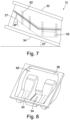
- a urinal bottle 10 includes a hollow body 12 having a neck 14 extending to a circular opening 16.
- the bottle 10 includes a flat base 18 which supports the urinal bottle 10 when placed on a surface.
- the neck 14 is angled upwardly away from the base 8.
- the opening 16 of the neck 14 defines the front end of the urinal bottle 1 in use.
- the neck 14 flares outwardly to the mouth opening 16.
- a split line A-A is defined along the length of the bottle 10.
- the split line A-A corresponds to the boundary between the upper and lower moulds tools when the bottle 10 is held within the mould.
- a lower rear wall section 20 is angled in a rearward direction away from the base 18 towards the split line A-A. Above the split line A-A the upper rear wall section 22 is angled forwardly to the upper surface 24 of the bottle 10.
- a two part split mould 26 is used to mould the bottle 10.
- the mould 26 includes an upper mould tool 28 and a lower mould tool 30.
- the upper mould tool 28 includes an upper mounting plate 32 and the lower tool 30 includes a lower mounting plate 34, the mounting plates being used to mount and support the mould tools within the moulding machine.
- the upper 28 and lower 30 mould tools are independently moveable.
- the upper 28 and lower 30 mould tools are shown in Figure 3 in the closed position with the two parts being held together in abutment.
- the interface 36 between the upper 28 and lower 30 mould tools corresponds to the split line A-A of the bottle 10.
- FIG 4 the upper 28 and lower 30 mould tools are shown in the open configuration.
- the upper 28 and lower 30 mould tools vertically separate relative to each other which may be by the upper tool 28 lifting vertically away from the lower tool 30.
- the upper mould tool 28 has a mould surface 38 including two mould recesses 40 configured to form the upper halves of two bottles
- the lower mould tool 30 has a mould surface 42 with a pair of mould recesses 44 corresponding to the mould recesses 38 of the upper tool 28 and configured to form the lower halves of two bottles, such that upper and lower mould recesses combine to form the entire bottle 10.
- Each mould surface 38, 42 comprises a stainless steel mesh gauze, as commonly used in pulp moulding tools, configured to allow the passage of water while retaining pulp material on its surface.
- a sealing rim 46 extends around the outer edge of each mould cavity or recess, the sealing ridges 46 of the upper 28 and lower 30 mould tools combining to form a seal with the mould tool 26 around each bottle 10 when the mould tool 26 is closed.
- the upper mould tool 28 also includes a vacuum chamber 52, as shown in Figure 6 .
- the vacuum chamber 52 is located above the inner surface of the mould surface 38.
- liquid must be drawn upwardly through the gauze of the mould surface 38 under the action of a vacuum applied to the vacuum chamber 52. The liquid must then be drawn from the vacuum chamber 52 and drained.
- a vacuum source is applied to the upper mould tool independently of the lower mould tool. This adds additional complexity to the mould assembly, and requires additional space for the requisite pipe work and associated fittings.
- that fact that the mould tools must be movable relative to each other adds additional complications in terms of accommodating the movement and ensuring the associated pipework does not interfere with this movement.
- a lower vacuum port 54 is provided that extends through the mould surface 42 of the lower mould tool 30.
- the vacuum port 54 comprises an aperture 56 formed in the mould surface 38 between the mould recesses 46.
- a wall 58 is arranged around the periphery of the aperture 56 and extends downwardly into the vacuum chamber 48.
- the lower vacuum port 54 has substantially elongate tear drop shape tapering in the rearward direction to conform to the narrowing space between the two mould recesses 46.
- the wall 58 is open at both its upper and lower end, with the wall 58 forming a socket for receiving a corresponding upper vacuum connector element 60 of the upper mould tool 28.
- the upper vacuum connector 60 comprises a wall 62 extending downwardly from the mould surface 38 of the upper mould tool 28.
- the wall 62 extends around an aperture 64 extending through the mould surface 38.
- the wall 62 has a shape corresponding to the shape of the wall 58 of the lower vacuum connector 54, and sized to fit within the lower wall 58 in a closely toleranced, sealed manner.
- the lower vacuum connector 54 and the upper vacuum connector 60 thereby cooperate in a plug and socket arrangement, with the plug arrangement defined by the upper vacuum connector 60 fitting and sealing within the socket arrangement of the lower vacuum connector 54.
- the vacuum connectors 54,60 are arranged to align and connect when the upper and lower mould tools 28,30 close. When connected, with the mould tools 28,30 closed, the vacuum connectors 54,60 form a sealed air conduit between the lower vacuum chamber 48 and the upper vacuum chamber 52. As such, when the mould tools 28,30 are closed and a vacuum is applied to the lower vacuum chamber 48, this same vacuum extends through the conduit airflow channel formed by the vacuum connectors 58,60 into the upper vacuum chamber 52. The vacuum is applied simultaneously to the upper mould surface 38 and the lower mould surface 42 by the single vacuum source connected to the lower mould tool 30.
- Liquid drawn through the gauze of the upper mould surface 38 is able to travel to the drain in the lower mould tool 30 through the vacuum channel 54.
- the liquid flows downwards under the action of gravity, thereby minimising the required vacuum.
- the mould tool 10 is angled forwardly at an angle of 23° defined as the angle between the base mounting plate and the horizontal. The angle further assists removal of the bottle 10 as discussed further below.
- a series of drainage channels are formed through the upper and lower mould tools 28,30.
- the drainage channels 62 are formed through the mould surfaces 38,42 in the regions surrounding the mould recesses 40,44.
- the drainage channels 62 align to define fluid pathways from the upper vacuum chamber 52 to the lower vacuum chamber 48.
- the channels 62 are angled such that when the mould tool 10 is angled forwardly at 23° the drainage channels extend vertically downwards.
- the mould 26 is retained at the 23° angle for both the moulding and extraction stages.
- the upper and lower mould tools 28, 30 are separated and, with the lower mould tool at an angle of 23° to the horizontal the bottle 10 is removed vertically from the lower mould tool 30.
- this vertical extraction with the mould tool angled forwardly would not be possible as the rear lower corner of the bottle would represent a negative draft in this orientation, preventing vertical extraction.
- This negative draft portion is indicated by eth hatched portion of Figure 1 . Therefore, with reference again to Figure 7 , the rear end surface 27 of the lower mould recess 44 is angled rearward such that it is at 26° to the vertical when the base 34 of the lower mould tool 30 is horizontal. As such, when the base 34 is angled upwardly at an angle of 23°, the rear end surface 27 remains rearwardly inclined by an angle of 3°, thereby avoiding a negative draft and permitting vertical removal of the bottle 10.
- the inner side of the upper mould surface 38 is raised to avoid troughs and traps where evacuated water may resist the vacuum suction applied to the upper vacuum chamber 52 through the vacuum channel 54.
- the vacuum channel 54 is located between the mould recesses 40 towards the front edge 50 of the upper mould tool 28.
- the recesses 38 are raised, convex elements.
- the regions of the mould surface 38 on the opposing sides of the recesses 40 are raised.
- the raised region 66 raises the inner surface to the upper edges of the recesses 40 to allow liquid to flow directly over the recesses 40 to the vacuum channel 54, rather than having to flow up and around the walls of the mould recesses 40. By providing a more direct flow path or reduced resistance, any pooling or trapping of the liquid is significantly reduced or avoided entirely.
- the raised region 66 may be formed during machining of the mould tool, or may be achieved by an insert provided into the mould tool after forming.
- the moulding machine includes a series of bottle removal spikes 68 for removing the formed bottles 10 from the moulds 26.
- the spike 68 is aligned with the opening 16 of the bottle 10.
- the spike 68 is elongate in form and its length is aligned with the length of the bottle 10.
- the spike 68 is then inserted into the neck 14 of the bottle 10 through the opening 16, as shown in Figure 9b .
- the mould 26 is angled forwardly at an angle of 23° the neck of the bottle 10 is oriented substantially horizontally, allowing the spike 68 to be inserted into the bottle 10 without interference.
- the spike 68 is inserted horizontally to the full insertion position of Figure 9b .
- the spike 68 is then lifted vertically, at which point the upper surface of the spike 68 engages the inner surface of the roof 12 of the bottle 10 and begins to lift the bottle 10 out of the mould 26.
- the bottle 10 may then be transported by moving the spike 68 to the desired location. As the bottle 10 is being lifted it is still in a wet condition and pliable, and as such prone to damage when being transported.
- the spike 68 is provided with a profile designed to conform to the shape of the bottle 10, to enable the spike 68 to cradle the bottle 10 during lifting with constant contact that prevents damage to the bottle 10.
- the spike 68 includes an elongate main body section 70.
- a proximal base 72 is located at one end of the body section 70 which secures to an actuator arm of the moulding machine.
- a tip 74 is formed at the opposing distal end.
- the tip 74 is angled upwardly away from the main body section 70 long the upper surface 76 of the spike 68.
- the change in angle between the upper surface of the main body section 70 and the tip 74 corresponds to the change in angle between the roof 12 of the bottle and the upper surface 15 of the neck 14.
- the upper surface 76 of the spike 68 confirms to the inner profile of the bottle 10 enabling it to function as a support finger supporting the bottle 10 along the entire length of contact with the bottle 10, as shown in Figure 11 .
- the upper and lower mould tools 28,30 are closed, with the sealing rim sealing the mould recesses within the mould 26.
- the mould 26 is then inserted into a vat of pulp slurry with pulp flowing into the mould recesses through the opening representing the opening of the bottle 10.
- the mould 26 is inserted into the pulp slurry vat while the mould tools 28,30 are closing.
- a vacuum is applied the mould tools 28,30 when they are closed and fully submerged in the pulp slurry.
- the vacuum is applied via the lower mould tool 30.
- the upper and lower mould tools 28,30 are mounted in upper and lower mould platens in such a manner that the mould tools 28,30 are angled forwardly at 23 degrees to the horizontal.
- the mould 26 is submerged vertically into the vat with the mould tools 28,30 oriented in this forwardly angled arrangement.
- a selected period is allowed for the pulp fibres to form against the mould 26.
- the mould 26 is then removed vertically from the slurry.
- a vacuum is applied to the vacuum chamber 48 of the lower mould tool 30, which may be a continuation of the forming vacuum applied while the mould 26 was submerged.
- the dewatering vacuum is simultaneously applied to the upper vacuum chamber through the vacuum connection channel 54. The vacuum draws water through the gauze surfaces of the mould tools 28,30 to dewater the pulp resting against the gauze.
- the bottle removal fingers 68 are inserted into the bottles 10.
- the embodiments described above as shown in the Figures include only two mould recesses for forming two bottles, this is for illustrative simplicity. In practice the mould tools may be formed to include mould recesses for forming multiple bottles and more than two.
- the fingers once fully inserted, may be lifted vertically a small distance to bring them into positive engagement with the roof of the bottles 10. This is done while the mould tools 28,30 remain closed. This supports the bottle 10 from above during initial engagement by the fingers 68. The mould tools 28,30 are then vertically separated revealing the fully formed bottles 10 held on the fingers 68. At this stage the bottles 10 are still very wet, and will typically comprise approximately 25% solids and 75% water.
- the fingers 68 are lifted vertically by the actuating arms to which they are connected to remove them from the lower tool 30 upon which they are resting. The arms are then retracted horizontally or otherwise moved to position them over a conveyor.
- the arms are then lowered towards the conveyor and then titled forwardly until the upper surface of the tips 74 of the finger 68 are sloped downwardly, which enables the bottles 10 to slide off the fingers 68 and onto the conveyor.
- the fingers are rotated through 23° to orientate the base surface 18 horizontally.
- the bottles 10 sit upon the conveyor on the flat base surface 18. The conveyor then transports the bottles 10 to the drying stage.
Landscapes
- Engineering & Computer Science (AREA)
- Manufacturing & Machinery (AREA)
- Paper (AREA)
- Moulds For Moulding Plastics Or The Like (AREA)
- Sanitary Device For Flush Toilet (AREA)
- Containers Having Bodies Formed In One Piece (AREA)
- Casting Or Compression Moulding Of Plastics Or The Like (AREA)
Claims (11)
- Un appareil de moulage de pâte comprenant :des premier et deuxième outils de moule (30, 28) ayant des première et deuxième cavités de moule, les outils de moule étant mobiles entre une configuration fermée dans laquelle les première et deuxième cavités de moule (40, 44) se combinent pour former un article en pâte moulée et une configuration de démoulage dans laquelle les premier et deuxième outils de moule (30, 28) sont séparés pour permettre le démoulage de l'article en pâte moulée ; etune source de vide raccordée au premier outil de moule (30) ;dans lequel les premier et deuxième outils de moule (30, 28) incluent chacun une surface de moule (38, 42), une cavité à vide (48, 52) située sur le côté arrière de la surface de moule, un canal de raccordement de fluide (56, 64), et un raccord (54, 60), les raccords (54, 60) des premier et deuxième outils de moule étant conçus pour raccorder fluidiquement les canaux de raccordement de fluide (56, 64) des premier et deuxième outils de moule (30, 28) lorsque les premier et deuxième outils de moule (30, 28) sont dans la configuration fermée de telle sorte qu'un vide appliqué à la cavité à vide (48) du premier outil de moule (30) par la source de vide soit simultanément appliqué à la cavité à vide (52) du deuxième outil de moule (28) par l'intermédiaire des canaux de raccordement de fluide (56, 64).
- Un appareil de moulage de pâte selon la revendication 1 dans lequel le premier outil de moule (30) inclut une surface de moule ayant une première cavité de moule poreuse formée en son sein pour le moulage d'une première portion d'un article en pâte moulée et le deuxième outil de moule (28) inclut une surface de moule ayant une deuxième cavité de moule poreuse formée en son sein pour le moulage d'une deuxième portion de l'article en pâte moulée, dans lequel chacune des cavités de moule (40, 44) inclut une surface de moule interne contre laquelle la pâte est formée et une surface arrière opposée, la source de vide étant raccordée au premier outil de moule (30) de telle sorte qu'elle applique un vide à la surface arrière de la cavité de moule (40), et les premier et deuxième raccords (54, 60) étant configurés pour raccorder fluidiquement les premier et deuxième outils de moule (30, 28) de telle sorte que le vide appliqué à la surface arrière du premier outil de moule (30) soit simultanément appliqué à la surface arrière du deuxième outil de moule (28) par l'intermédiaire des premier et deuxième raccords de fluide (54, 60).
- Un appareil de moulage de pâte selon la revendication 1 ou la revendication 2 dans lequel les premier et deuxième outils de moule incluent chacun un corps d'outil de moule et les canaux de raccordement de fluide sont formés dans les corps d'outil de moule des premier et deuxième outils de moule respectivement, et les raccords sont conçus pour raccorder les premier et deuxième canaux d'une manière hermétique lorsque les outils de moule sont fermés.
- Un appareil de moulage de pâte selon la revendication 3 dans lequel le raccord comprend un élément de raccord femelle disposé sur l'un des premier et deuxième outils de moule (30, 28) et un élément de raccord mâle disposé sur l'autre des premier et deuxième outils de moule (30, 28) configuré pour être reçu dans l'élément de raccord femelle d'une manière hermétique afin de raccorder les premier et deuxième canaux de fluide.
- Un appareil de moulage de pâte selon la revendication 4 dans lequel les surfaces de moule des premier et deuxième outils de moule (30, 28) se font face dans la position fermée et l'élément de raccord femelle rentre dans la surface de moule dudit un des premier et deuxième outils de moule (30, 28) et l'élément de raccord mâle fait saillie de la surface de moule dudit autre des premier et deuxième outils de moule (30, 28), les éléments de raccord étant conçus de telle sorte que l'élément de raccord mâle soit reçu dans l'élément de raccord femelle lorsque les outils de moule sont fermés.
- Un appareil de moulage de pâte selon la revendication 5 dans lequel les premier et deuxième outils de moule (30, 28) sont conçus de telle sorte que, lors de l'utilisation, le premier outil de moule (30) soit l'outil de moule inférieur et le deuxième outil de moule (28) soit l'outil de moule supérieur.
- Un appareil de moulage de pâte selon la revendication 6 dans lequel les premier et deuxième outils de moule incluent un ou plusieurs canaux de drainage formés en leur sein qui s'alignent lorsque les premier et deuxième outils de moule (30, 28) sont fermés pour permettre à du liquide d'être drainé depuis la cavité à vide supérieure jusqu'à la cavité à vide inférieure.
- Un appareil de moulage de pâte selon la revendication 6 ou la revendication 7 dans lequel le côté arrière de la surface de moule supérieure inclut des régions surélevées conçues pour canaliser du liquide vers le raccord de fluide.
- Un appareil de moulage de pâte selon n'importe lesquelles des revendications précédentes 6 à 8 dans lequel un ou plusieurs canaux de drainage sont formés à travers les outils de moule supérieur et inférieur (30, 28) pour canaliser du liquide depuis la cavité à vide supérieure jusque dans la cavité à vide inférieure.
- Un appareil de moulage de pâte selon la revendication 9 dans lequel les outils de moule supérieur et inférieur (30, 28) sont inclinés vers l'avant, lors de l'utilisation, d'entre 15 et 35 degrés par rapport à l'horizontale, et dans lequel l'angle des canaux de drainage est sélectionné de telle sorte qu'ils soient orientés de façon substantiellement verticale lorsque les outils de moule sont inclinés vers l'avant.
- Un appareil de moulage de pâte selon n'importe quelle revendication précédente dans lequel les premier et deuxième outils de moule (30, 28) sont configurés pour former un urinal ayant un corps et un col s'étendant depuis le corps jusqu'à un orifice, dans lequel l'emplacement de l'orifice d'urinal définit l'avant du moule, et le raccord de fluide est situé à l'extrémité avant des premier et deuxième outils de moule (30, 28).
Applications Claiming Priority (2)
| Application Number | Priority Date | Filing Date | Title |
|---|---|---|---|
| GBGB1421798.8A GB201421798D0 (en) | 2014-12-08 | 2014-12-08 | An apparatus for forming moulded fibre urinal bottles |
| PCT/GB2015/053763 WO2016092296A1 (fr) | 2014-12-08 | 2015-12-08 | Appareil de formation de bouteilles d'urinoir en fibres moulées |
Publications (2)
| Publication Number | Publication Date |
|---|---|
| EP3230525A1 EP3230525A1 (fr) | 2017-10-18 |
| EP3230525B1 true EP3230525B1 (fr) | 2024-10-23 |
Family
ID=52425622
Family Applications (1)
| Application Number | Title | Priority Date | Filing Date |
|---|---|---|---|
| EP15816831.0A Active EP3230525B1 (fr) | 2014-12-08 | 2015-12-08 | Appareil de formation de bouteilles d'urinoir en fibres moulées |
Country Status (8)
| Country | Link |
|---|---|
| EP (1) | EP3230525B1 (fr) |
| CN (1) | CN107548422B (fr) |
| AU (1) | AU2015359137B2 (fr) |
| CA (1) | CA3007766C (fr) |
| ES (1) | ES3005384T3 (fr) |
| GB (2) | GB201421798D0 (fr) |
| PL (1) | PL3230525T3 (fr) |
| WO (1) | WO2016092296A1 (fr) |
Families Citing this family (3)
| Publication number | Priority date | Publication date | Assignee | Title |
|---|---|---|---|---|
| CN108316057A (zh) * | 2018-02-07 | 2018-07-24 | 永发(河南)模塑科技发展有限公司 | 一种纸浆模塑模具标准化高度调节块 |
| CN111206458B (zh) * | 2020-01-09 | 2022-06-07 | 广西福斯派环保科技有限公司 | 用于生产纸吸管的设备及其生产方法 |
| GB2631429A (en) * | 2023-06-29 | 2025-01-08 | Pulpex Ltd | Mould part and moulding station |
Family Cites Families (7)
| Publication number | Priority date | Publication date | Assignee | Title |
|---|---|---|---|---|
| US3585107A (en) * | 1967-05-15 | 1971-06-15 | American Mach & Foundry | Accretion apparatus |
| CA861385A (en) * | 1969-04-11 | 1971-01-19 | R. Emery John | Moulding machine |
| EP0745727A3 (fr) * | 1995-06-02 | 1997-06-25 | Broadway Holdings Pte Ltd | Procédé et dispositif pour le moulage de corps fibreux avec séchage forcé |
| CN2230773Y (zh) * | 1995-10-19 | 1996-07-10 | 中日合资大连绿洲食品包装有限公司 | 植物纤维包装制品自动成型机 |
| CN2394949Y (zh) * | 1999-10-29 | 2000-09-06 | 江阴市飞龙电化设备有限公司 | 纸浆模塑成型机 |
| DE60033358T2 (de) * | 1999-11-17 | 2007-10-31 | Kao Corp. | Verfahren zur Herstellung von faserigen Formteilen |
| WO2012033449A1 (fr) * | 2010-09-07 | 2012-03-15 | Pakit International Trading Company Inc. | Agencement de moule pour pâte |
-
2014
- 2014-12-08 GB GBGB1421798.8A patent/GB201421798D0/en not_active Ceased
-
2015
- 2015-12-08 AU AU2015359137A patent/AU2015359137B2/en active Active
- 2015-12-08 WO PCT/GB2015/053763 patent/WO2016092296A1/fr not_active Ceased
- 2015-12-08 ES ES15816831T patent/ES3005384T3/es active Active
- 2015-12-08 EP EP15816831.0A patent/EP3230525B1/fr active Active
- 2015-12-08 CA CA3007766A patent/CA3007766C/fr active Active
- 2015-12-08 GB GB1618211.5A patent/GB2540090B/en active Active
- 2015-12-08 CN CN201580075722.6A patent/CN107548422B/zh active Active
- 2015-12-08 PL PL15816831.0T patent/PL3230525T3/pl unknown
Also Published As
| Publication number | Publication date |
|---|---|
| ES3005384T3 (en) | 2025-03-14 |
| AU2015359137B2 (en) | 2020-11-12 |
| WO2016092296A1 (fr) | 2016-06-16 |
| GB2540090A (en) | 2017-01-04 |
| AU2015359137A1 (en) | 2017-07-27 |
| GB2540090B (en) | 2017-08-02 |
| CN107548422A (zh) | 2018-01-05 |
| CA3007766C (fr) | 2021-02-09 |
| GB201618211D0 (en) | 2016-12-14 |
| CA3007766A1 (fr) | 2016-06-16 |
| EP3230525A1 (fr) | 2017-10-18 |
| PL3230525T3 (pl) | 2025-04-14 |
| CN107548422B (zh) | 2019-09-06 |
| GB201421798D0 (en) | 2015-01-21 |
Similar Documents
| Publication | Publication Date | Title |
|---|---|---|
| CN103015273B (zh) | 植物纤维模塑制品全自动制造方法及模塑成型切边一体机 | |
| CN203080367U (zh) | 全自动植物纤维模塑成型定型切边一体机 | |
| EP3230525B1 (fr) | Appareil de formation de bouteilles d'urinoir en fibres moulées | |
| CN109318466B (zh) | 一种箱壳自动吸塑成型机及自动吸塑成型方法 | |
| GB2571454A (en) | An apparatus for forming moulded fibre urinal bottles | |
| US20090315221A1 (en) | Method for demolding ceramic products and apparatus for implementing the method | |
| KR200454431Y1 (ko) | 김 제조장치 | |
| CN211306691U (zh) | 一种传送式自动注浆成型机 | |
| CN109689316B (zh) | 铸模、浇铸装置、对铸件脱水的方法以及生产铸件的方法 | |
| CN110385768A (zh) | 一种传送式自动注浆成型机 | |
| IT201700008148A1 (it) | Impianto di produzione di articoli sanitari | |
| CN104652178A (zh) | 大型厚体纸浆模压工艺及设备 | |
| CN207952125U (zh) | 一种高效的模具清理装置 | |
| CN120306579B (zh) | 一种液压阀组件铸造成型处理设备 | |
| CN118808585B (zh) | 一种压铸机用清理设备 | |
| CN205029874U (zh) | 高效率去毛刺的全自动纸盆成型机 | |
| KR101645014B1 (ko) | 해태 초제기 | |
| TWI751018B (zh) | 漿料模塑成型系統及其漿料補給裝置 | |
| CN215413008U (zh) | 一种日用陶瓷的一次干燥系统 | |
| CN108716169A (zh) | 餐盘初品成型机 | |
| CN113545383B (zh) | 一种食品加工生产线及加工生产方法 | |
| CN203977235U (zh) | 一种植物纤维模塑杯盖制品全自动制造设备 | |
| CN114351509A (zh) | 一种纸模餐具成型机及全自动纸模餐具生产设备 | |
| CN104527097A (zh) | 一种开泡装置 | |
| CN108453870A (zh) | 一种改进型高性能陶瓷结构件制备技术设备 |
Legal Events
| Date | Code | Title | Description |
|---|---|---|---|
| STAA | Information on the status of an ep patent application or granted ep patent |
Free format text: STATUS: THE INTERNATIONAL PUBLICATION HAS BEEN MADE |
|
| PUAI | Public reference made under article 153(3) epc to a published international application that has entered the european phase |
Free format text: ORIGINAL CODE: 0009012 |
|
| STAA | Information on the status of an ep patent application or granted ep patent |
Free format text: STATUS: REQUEST FOR EXAMINATION WAS MADE |
|
| 17P | Request for examination filed |
Effective date: 20170707 |
|
| AK | Designated contracting states |
Kind code of ref document: A1 Designated state(s): AL AT BE BG CH CY CZ DE DK EE ES FI FR GB GR HR HU IE IS IT LI LT LU LV MC MK MT NL NO PL PT RO RS SE SI SK SM TR |
|
| AX | Request for extension of the european patent |
Extension state: BA ME |
|
| DAV | Request for validation of the european patent (deleted) | ||
| DAX | Request for extension of the european patent (deleted) | ||
| RAP1 | Party data changed (applicant data changed or rights of an application transferred) |
Owner name: PULP TECH CO., LIMITED |
|
| RIN1 | Information on inventor provided before grant (corrected) |
Inventor name: KHAN, JALALUDDIN |
|
| STAA | Information on the status of an ep patent application or granted ep patent |
Free format text: STATUS: EXAMINATION IS IN PROGRESS |
|
| 17Q | First examination report despatched |
Effective date: 20210401 |
|
| GRAP | Despatch of communication of intention to grant a patent |
Free format text: ORIGINAL CODE: EPIDOSNIGR1 |
|
| STAA | Information on the status of an ep patent application or granted ep patent |
Free format text: STATUS: GRANT OF PATENT IS INTENDED |
|
| INTG | Intention to grant announced |
Effective date: 20240507 |
|
| GRAJ | Information related to disapproval of communication of intention to grant by the applicant or resumption of examination proceedings by the epo deleted |
Free format text: ORIGINAL CODE: EPIDOSDIGR1 |
|
| STAA | Information on the status of an ep patent application or granted ep patent |
Free format text: STATUS: EXAMINATION IS IN PROGRESS |
|
| GRAS | Grant fee paid |
Free format text: ORIGINAL CODE: EPIDOSNIGR3 |
|
| STAA | Information on the status of an ep patent application or granted ep patent |
Free format text: STATUS: GRANT OF PATENT IS INTENDED |
|
| GRAP | Despatch of communication of intention to grant a patent |
Free format text: ORIGINAL CODE: EPIDOSNIGR1 |
|
| GRAA | (expected) grant |
Free format text: ORIGINAL CODE: 0009210 |
|
| STAA | Information on the status of an ep patent application or granted ep patent |
Free format text: STATUS: THE PATENT HAS BEEN GRANTED |
|
| INTG | Intention to grant announced |
Effective date: 20240917 |
|
| AK | Designated contracting states |
Kind code of ref document: B1 Designated state(s): AL AT BE BG CH CY CZ DE DK EE ES FI FR GB GR HR HU IE IS IT LI LT LU LV MC MK MT NL NO PL PT RO RS SE SI SK SM TR |
|
| REG | Reference to a national code |
Ref country code: GB Ref legal event code: FG4D |
|
| REG | Reference to a national code |
Ref country code: CH Ref legal event code: EP |
|
| REG | Reference to a national code |
Ref country code: DE Ref legal event code: R096 Ref document number: 602015090215 Country of ref document: DE |
|
| REG | Reference to a national code |
Ref country code: IE Ref legal event code: FG4D |
|
| REG | Reference to a national code |
Ref country code: LT Ref legal event code: MG9D |
|
| REG | Reference to a national code |
Ref country code: NL Ref legal event code: MP Effective date: 20241023 |
|
| REG | Reference to a national code |
Ref country code: ES Ref legal event code: FG2A Ref document number: 3005384 Country of ref document: ES Kind code of ref document: T3 Effective date: 20250314 |
|
| REG | Reference to a national code |
Ref country code: AT Ref legal event code: MK05 Ref document number: 1734936 Country of ref document: AT Kind code of ref document: T Effective date: 20241023 |
|
| PG25 | Lapsed in a contracting state [announced via postgrant information from national office to epo] |
Ref country code: NL Free format text: LAPSE BECAUSE OF FAILURE TO SUBMIT A TRANSLATION OF THE DESCRIPTION OR TO PAY THE FEE WITHIN THE PRESCRIBED TIME-LIMIT Effective date: 20241023 |
|
| PG25 | Lapsed in a contracting state [announced via postgrant information from national office to epo] |
Ref country code: NL Free format text: LAPSE BECAUSE OF FAILURE TO SUBMIT A TRANSLATION OF THE DESCRIPTION OR TO PAY THE FEE WITHIN THE PRESCRIBED TIME-LIMIT Effective date: 20241023 |
|
| PG25 | Lapsed in a contracting state [announced via postgrant information from national office to epo] |
Ref country code: PT Free format text: LAPSE BECAUSE OF FAILURE TO SUBMIT A TRANSLATION OF THE DESCRIPTION OR TO PAY THE FEE WITHIN THE PRESCRIBED TIME-LIMIT Effective date: 20250224 Ref country code: IS Free format text: LAPSE BECAUSE OF FAILURE TO SUBMIT A TRANSLATION OF THE DESCRIPTION OR TO PAY THE FEE WITHIN THE PRESCRIBED TIME-LIMIT Effective date: 20250223 Ref country code: HR Free format text: LAPSE BECAUSE OF FAILURE TO SUBMIT A TRANSLATION OF THE DESCRIPTION OR TO PAY THE FEE WITHIN THE PRESCRIBED TIME-LIMIT Effective date: 20241023 |
|
| PG25 | Lapsed in a contracting state [announced via postgrant information from national office to epo] |
Ref country code: FI Free format text: LAPSE BECAUSE OF FAILURE TO SUBMIT A TRANSLATION OF THE DESCRIPTION OR TO PAY THE FEE WITHIN THE PRESCRIBED TIME-LIMIT Effective date: 20241023 |
|
| PG25 | Lapsed in a contracting state [announced via postgrant information from national office to epo] |
Ref country code: BG Free format text: LAPSE BECAUSE OF FAILURE TO SUBMIT A TRANSLATION OF THE DESCRIPTION OR TO PAY THE FEE WITHIN THE PRESCRIBED TIME-LIMIT Effective date: 20241023 |
|
| PG25 | Lapsed in a contracting state [announced via postgrant information from national office to epo] |
Ref country code: NO Free format text: LAPSE BECAUSE OF FAILURE TO SUBMIT A TRANSLATION OF THE DESCRIPTION OR TO PAY THE FEE WITHIN THE PRESCRIBED TIME-LIMIT Effective date: 20250123 |
|
| PG25 | Lapsed in a contracting state [announced via postgrant information from national office to epo] |
Ref country code: AT Free format text: LAPSE BECAUSE OF FAILURE TO SUBMIT A TRANSLATION OF THE DESCRIPTION OR TO PAY THE FEE WITHIN THE PRESCRIBED TIME-LIMIT Effective date: 20241023 Ref country code: GR Free format text: LAPSE BECAUSE OF FAILURE TO SUBMIT A TRANSLATION OF THE DESCRIPTION OR TO PAY THE FEE WITHIN THE PRESCRIBED TIME-LIMIT Effective date: 20250124 Ref country code: LV Free format text: LAPSE BECAUSE OF FAILURE TO SUBMIT A TRANSLATION OF THE DESCRIPTION OR TO PAY THE FEE WITHIN THE PRESCRIBED TIME-LIMIT Effective date: 20241023 |
|
| PG25 | Lapsed in a contracting state [announced via postgrant information from national office to epo] |
Ref country code: RS Free format text: LAPSE BECAUSE OF FAILURE TO SUBMIT A TRANSLATION OF THE DESCRIPTION OR TO PAY THE FEE WITHIN THE PRESCRIBED TIME-LIMIT Effective date: 20250123 |
|
| PG25 | Lapsed in a contracting state [announced via postgrant information from national office to epo] |
Ref country code: SM Free format text: LAPSE BECAUSE OF FAILURE TO SUBMIT A TRANSLATION OF THE DESCRIPTION OR TO PAY THE FEE WITHIN THE PRESCRIBED TIME-LIMIT Effective date: 20241023 |
|
| PG25 | Lapsed in a contracting state [announced via postgrant information from national office to epo] |
Ref country code: MC Free format text: LAPSE BECAUSE OF FAILURE TO SUBMIT A TRANSLATION OF THE DESCRIPTION OR TO PAY THE FEE WITHIN THE PRESCRIBED TIME-LIMIT Effective date: 20241023 |
|
| PG25 | Lapsed in a contracting state [announced via postgrant information from national office to epo] |
Ref country code: DK Free format text: LAPSE BECAUSE OF FAILURE TO SUBMIT A TRANSLATION OF THE DESCRIPTION OR TO PAY THE FEE WITHIN THE PRESCRIBED TIME-LIMIT Effective date: 20241023 |
|
| PG25 | Lapsed in a contracting state [announced via postgrant information from national office to epo] |
Ref country code: EE Free format text: LAPSE BECAUSE OF FAILURE TO SUBMIT A TRANSLATION OF THE DESCRIPTION OR TO PAY THE FEE WITHIN THE PRESCRIBED TIME-LIMIT Effective date: 20241023 |
|
| PG25 | Lapsed in a contracting state [announced via postgrant information from national office to epo] |
Ref country code: RO Free format text: LAPSE BECAUSE OF FAILURE TO SUBMIT A TRANSLATION OF THE DESCRIPTION OR TO PAY THE FEE WITHIN THE PRESCRIBED TIME-LIMIT Effective date: 20241023 |
|
| REG | Reference to a national code |
Ref country code: DE Ref legal event code: R097 Ref document number: 602015090215 Country of ref document: DE |
|
| PG25 | Lapsed in a contracting state [announced via postgrant information from national office to epo] |
Ref country code: SK Free format text: LAPSE BECAUSE OF FAILURE TO SUBMIT A TRANSLATION OF THE DESCRIPTION OR TO PAY THE FEE WITHIN THE PRESCRIBED TIME-LIMIT Effective date: 20241023 |
|
| PG25 | Lapsed in a contracting state [announced via postgrant information from national office to epo] |
Ref country code: CZ Free format text: LAPSE BECAUSE OF FAILURE TO SUBMIT A TRANSLATION OF THE DESCRIPTION OR TO PAY THE FEE WITHIN THE PRESCRIBED TIME-LIMIT Effective date: 20241023 |
|
| REG | Reference to a national code |
Ref country code: CH Ref legal event code: PL |
|
| PG25 | Lapsed in a contracting state [announced via postgrant information from national office to epo] |
Ref country code: LU Free format text: LAPSE BECAUSE OF NON-PAYMENT OF DUE FEES Effective date: 20241208 |
|
| PLBE | No opposition filed within time limit |
Free format text: ORIGINAL CODE: 0009261 |
|
| STAA | Information on the status of an ep patent application or granted ep patent |
Free format text: STATUS: NO OPPOSITION FILED WITHIN TIME LIMIT |
|
| PG25 | Lapsed in a contracting state [announced via postgrant information from national office to epo] |
Ref country code: SE Free format text: LAPSE BECAUSE OF FAILURE TO SUBMIT A TRANSLATION OF THE DESCRIPTION OR TO PAY THE FEE WITHIN THE PRESCRIBED TIME-LIMIT Effective date: 20241023 |
|
| GBPC | Gb: european patent ceased through non-payment of renewal fee |
Effective date: 20250123 |
|
| 26N | No opposition filed |
Effective date: 20250724 |
|
| REG | Reference to a national code |
Ref country code: BE Ref legal event code: MM Effective date: 20241231 |
|
| PG25 | Lapsed in a contracting state [announced via postgrant information from national office to epo] |
Ref country code: GB Free format text: LAPSE BECAUSE OF NON-PAYMENT OF DUE FEES Effective date: 20250123 Ref country code: BE Free format text: LAPSE BECAUSE OF NON-PAYMENT OF DUE FEES Effective date: 20241231 |
|
| PG25 | Lapsed in a contracting state [announced via postgrant information from national office to epo] |
Ref country code: CH Free format text: LAPSE BECAUSE OF NON-PAYMENT OF DUE FEES Effective date: 20241231 |
|
| PG25 | Lapsed in a contracting state [announced via postgrant information from national office to epo] |
Ref country code: IE Free format text: LAPSE BECAUSE OF NON-PAYMENT OF DUE FEES Effective date: 20241208 |
|
| PGFP | Annual fee paid to national office [announced via postgrant information from national office to epo] |
Ref country code: FR Payment date: 20251229 Year of fee payment: 11 |
|
| PGFP | Annual fee paid to national office [announced via postgrant information from national office to epo] |
Ref country code: PL Payment date: 20251126 Year of fee payment: 11 |
|
| PGFP | Annual fee paid to national office [announced via postgrant information from national office to epo] |
Ref country code: ES Payment date: 20260114 Year of fee payment: 11 |
|
| PGFP | Annual fee paid to national office [announced via postgrant information from national office to epo] |
Ref country code: DE Payment date: 20251230 Year of fee payment: 11 |
|
| PGFP | Annual fee paid to national office [announced via postgrant information from national office to epo] |
Ref country code: IT Payment date: 20251229 Year of fee payment: 11 |