EP3230558B1 - Betrieb eines mehrstrahligen phasengesteuerten akustischen wandlers für bohrlochanwendungen - Google Patents
Betrieb eines mehrstrahligen phasengesteuerten akustischen wandlers für bohrlochanwendungen Download PDFInfo
- Publication number
- EP3230558B1 EP3230558B1 EP15866748.5A EP15866748A EP3230558B1 EP 3230558 B1 EP3230558 B1 EP 3230558B1 EP 15866748 A EP15866748 A EP 15866748A EP 3230558 B1 EP3230558 B1 EP 3230558B1
- Authority
- EP
- European Patent Office
- Prior art keywords
- acoustic
- borehole wall
- borehole
- array
- transducers
- Prior art date
- Legal status (The legal status is an assumption and is not a legal conclusion. Google has not performed a legal analysis and makes no representation as to the accuracy of the status listed.)
- Active
Links
Images






Classifications
-
- G—PHYSICS
- G01—MEASURING; TESTING
- G01V—GEOPHYSICS; GRAVITATIONAL MEASUREMENTS; DETECTING MASSES OR OBJECTS; TAGS
- G01V1/00—Seismology; Seismic or acoustic prospecting or detecting
- G01V1/40—Seismology; Seismic or acoustic prospecting or detecting specially adapted for well-logging
- G01V1/44—Seismology; Seismic or acoustic prospecting or detecting specially adapted for well-logging using generators and receivers in the same well
-
- G—PHYSICS
- G01—MEASURING; TESTING
- G01S—RADIO DIRECTION-FINDING; RADIO NAVIGATION; DETERMINING DISTANCE OR VELOCITY BY USE OF RADIO WAVES; LOCATING OR PRESENCE-DETECTING BY USE OF THE REFLECTION OR RERADIATION OF RADIO WAVES; ANALOGOUS ARRANGEMENTS USING OTHER WAVES
- G01S15/00—Systems using the reflection or reradiation of acoustic waves, e.g. sonar systems
- G01S15/88—Sonar systems specially adapted for specific applications
- G01S15/89—Sonar systems specially adapted for specific applications for mapping or imaging
-
- E—FIXED CONSTRUCTIONS
- E21—EARTH OR ROCK DRILLING; MINING
- E21B—EARTH OR ROCK DRILLING; OBTAINING OIL, GAS, WATER, SOLUBLE OR MELTABLE MATERIALS OR A SLURRY OF MINERALS FROM WELLS
- E21B47/00—Survey of boreholes or wells
- E21B47/002—Survey of boreholes or wells by visual inspection
-
- E—FIXED CONSTRUCTIONS
- E21—EARTH OR ROCK DRILLING; MINING
- E21B—EARTH OR ROCK DRILLING; OBTAINING OIL, GAS, WATER, SOLUBLE OR MELTABLE MATERIALS OR A SLURRY OF MINERALS FROM WELLS
- E21B47/00—Survey of boreholes or wells
- E21B47/002—Survey of boreholes or wells by visual inspection
- E21B47/0025—Survey of boreholes or wells by visual inspection generating an image of the borehole wall using down-hole measurements, e.g. acoustic or electric
-
- G—PHYSICS
- G01—MEASURING; TESTING
- G01S—RADIO DIRECTION-FINDING; RADIO NAVIGATION; DETERMINING DISTANCE OR VELOCITY BY USE OF RADIO WAVES; LOCATING OR PRESENCE-DETECTING BY USE OF THE REFLECTION OR RERADIATION OF RADIO WAVES; ANALOGOUS ARRANGEMENTS USING OTHER WAVES
- G01S15/00—Systems using the reflection or reradiation of acoustic waves, e.g. sonar systems
- G01S15/88—Sonar systems specially adapted for specific applications
-
- G—PHYSICS
- G01—MEASURING; TESTING
- G01S—RADIO DIRECTION-FINDING; RADIO NAVIGATION; DETERMINING DISTANCE OR VELOCITY BY USE OF RADIO WAVES; LOCATING OR PRESENCE-DETECTING BY USE OF THE REFLECTION OR RERADIATION OF RADIO WAVES; ANALOGOUS ARRANGEMENTS USING OTHER WAVES
- G01S7/00—Details of systems according to groups G01S13/00, G01S15/00, G01S17/00
- G01S7/52—Details of systems according to groups G01S13/00, G01S15/00, G01S17/00 of systems according to group G01S15/00
- G01S7/52003—Techniques for enhancing spatial resolution of targets
-
- G—PHYSICS
- G01—MEASURING; TESTING
- G01S—RADIO DIRECTION-FINDING; RADIO NAVIGATION; DETERMINING DISTANCE OR VELOCITY BY USE OF RADIO WAVES; LOCATING OR PRESENCE-DETECTING BY USE OF THE REFLECTION OR RERADIATION OF RADIO WAVES; ANALOGOUS ARRANGEMENTS USING OTHER WAVES
- G01S7/00—Details of systems according to groups G01S13/00, G01S15/00, G01S17/00
- G01S7/52—Details of systems according to groups G01S13/00, G01S15/00, G01S17/00 of systems according to group G01S15/00
- G01S7/523—Details of pulse systems
- G01S7/524—Transmitters
-
- G—PHYSICS
- G01—MEASURING; TESTING
- G01S—RADIO DIRECTION-FINDING; RADIO NAVIGATION; DETERMINING DISTANCE OR VELOCITY BY USE OF RADIO WAVES; LOCATING OR PRESENCE-DETECTING BY USE OF THE REFLECTION OR RERADIATION OF RADIO WAVES; ANALOGOUS ARRANGEMENTS USING OTHER WAVES
- G01S7/00—Details of systems according to groups G01S13/00, G01S15/00, G01S17/00
- G01S7/52—Details of systems according to groups G01S13/00, G01S15/00, G01S17/00 of systems according to group G01S15/00
- G01S7/523—Details of pulse systems
- G01S7/526—Receivers
-
- G—PHYSICS
- G10—MUSICAL INSTRUMENTS; ACOUSTICS
- G10K—SOUND-PRODUCING DEVICES; METHODS OR DEVICES FOR PROTECTING AGAINST, OR FOR DAMPING, NOISE OR OTHER ACOUSTIC WAVES IN GENERAL; ACOUSTICS NOT OTHERWISE PROVIDED FOR
- G10K11/00—Methods or devices for transmitting, conducting or directing sound in general; Methods or devices for protecting against, or for damping, noise or other acoustic waves in general
- G10K11/18—Methods or devices for transmitting, conducting or directing sound
- G10K11/26—Sound-focusing or directing, e.g. scanning
- G10K11/34—Sound-focusing or directing, e.g. scanning using electrical steering of transducer arrays, e.g. beam steering
-
- G—PHYSICS
- G10—MUSICAL INSTRUMENTS; ACOUSTICS
- G10K—SOUND-PRODUCING DEVICES; METHODS OR DEVICES FOR PROTECTING AGAINST, OR FOR DAMPING, NOISE OR OTHER ACOUSTIC WAVES IN GENERAL; ACOUSTICS NOT OTHERWISE PROVIDED FOR
- G10K11/00—Methods or devices for transmitting, conducting or directing sound in general; Methods or devices for protecting against, or for damping, noise or other acoustic waves in general
- G10K11/18—Methods or devices for transmitting, conducting or directing sound
- G10K11/26—Sound-focusing or directing, e.g. scanning
- G10K11/34—Sound-focusing or directing, e.g. scanning using electrical steering of transducer arrays, e.g. beam steering
- G10K11/341—Circuits therefor
- G10K11/346—Circuits therefor using phase variation
Definitions
- Earth formations may be used for various purposes such as hydrocarbon production, geothermal production, and carbon dioxide sequestration.
- the formation is characterized by performing measurements of many different properties using one or more tools conveyed through a borehole penetrating the formation.
- One category of tools is acoustic tools that use sound waves to perform various measurements such as imaging a wall of the borehole to determine borehole rugosity as one example.
- conveying a tool through the borehole for logging purposes may require that other borehole activities be suspended while the logging is taking place. This, unfortunately, can lead to increased production or exploration costs.
- acoustic downhole tools were developed that reduce the amount of time required to perform downhole acoustic measurements.
- a tool for investigating a borehole comprising at least one matrix of acoustical transducer elements organized on respective cylindrical surfaces as phased arrays. Each transducer element of the respective at least one matrix may be individually excited or measured.
- the tool allows for generation of a number of type of beams, for instance focused or unfocused, on the inner wall of the borehole.
- the unfocused beam may be rotated all around the cylindrical array by displacing an aperture of active elements and applying a similar signal pattern as before to the elements of the new aperture.
- EP 1 906 207 A1 a technique for forming an ultrasound image is known.
- the technique involves a plurality of transducers, each being operable to transmit and receive an ultrasound signal along a scan line determined based on a virtual common point.
- an ultrasonic diagnostic system is known using a technique where a side lobe of a first beam pattern of an ultrasonic diagnostic system is reduced by generating a second beam pattern.
- the azimuth of the main beam of the second beam pattern is made coincident with the side lobe of the first beam pattern.
- the apparatus includes: a carrier configured to be conveyed through the borehole; an array of acoustic transducers disposed on the carrier and configured to transmit an acoustic signal toward the borehole wall and receive an acoustic return signal from the borehole wall; a controller configured to (i) scan a section of the borehole wall with first acoustic beams that are transmitted by a series of sets of acoustic transducers in the array to produce adjacent first acoustic measurements that are spaced a first distance D1 apart along the borehole wall, each set having at least one transducer that is different from an adjacent set, (ii) steer a second acoustic beam along the section of the borehole wall using one set of acoustic transducers in the array to produce adjacent second acoustic measurements that are a second distance D2 apart along the borehole wall, and (iii) image the borehole wall using the
- the method includes: conveying a carrier through the borehole, the carrier having disposed thereon an array of acoustic transducers, the array of acoustic transducers being configured to transmit an acoustic signal toward the borehole wall and receive an acoustic return signal from the borehole wall; scanning a section of the borehole wall with first acoustic beams that are transmitted by a series of sets of acoustic transducers in the array to produce adjacent first acoustic measurements that are spaced a first distance D1 apart along the borehole wall, each set having at least one transducer that is different from an adjacent set; steering a second acoustic beam along the section of the borehole wall using one set of acoustic transducers in the array to produce adjacent second acoustic measurements that are a second distance D2 apart from each other along the borehole wall, wherein the second acoustic measurements form an
- Acoustic measurements are performed at points along a perimeter of the borehole at a certain depth.
- the measurements are performed using an array of acoustic transducers that can transmit acoustic energy toward the borehole wall and receive return acoustic energy from the borehole wall.
- An acoustic beam is generated by a set of acoustic transducers in the array that can image a point or area on the borehole wall.
- another acoustic beam can be generated by one set of acoustic transducers and this beam can be moved or steered along the perimeter by applying a time delay related to each of the acoustic transducers for coordinating emission and/or reception of acoustic energy in the set.
- the steered acoustic beams are used to image points of the borehole wall between scanned image points. In this manner, a precise high resolution image of the borehole wall may be obtained.
- FIG. 1 a side view is illustrated of an exemplary embodiment of a downhole acoustic tool 10 disposed in a borehole 2 penetrating the earth 3, which includes a formation 4 having formation layers 4A-4D.
- the formation layers are only illustrated on the right side of the borehole, but are also intended to be illustrative of surrounding the borehole.
- Each of the formation layers may have different measureable characteristics such as a lithology different from a lithology of adjacent layers.
- the borehole 2 or portions of the borehole 2 may be lined with a casing 7.
- the acoustic tool 10 is conveyed through the borehole 2 by a carrier 5.
- the carrier 5 is an armored wireline 6.
- the wireline 6 can provide communications (i.e., telemetry) between the downhole tool 10 and a computer processing system 9 disposed at the surface of the earth 3. Communications can include sending measurements uphole to the computer processing system 9 or commands downhole to the downhole tool 10.
- the wireline 6 can supply electrical power to the acoustic tool 10.
- the downhole tool 10 includes downhole electronics 8.
- the operating, control, processing, and display functions of the disclosure may be performed by the downhole electronics 8, the computer processing system 9, or a combination thereof.
- the downhole electronics 8 and/or the computer processing system 9 may be referred to as a controller.
- the carrier 5 can be a drill string or drill tubular. Telemetry for LWD or MWD may include pulsed-mud or wired drill pipe. In wireline, LWD, or MWD embodiments, measurement data may be downloaded in real time or after the downhole NMR tool 10 is retrieved from the borehole 2.
- the acoustic tool 10 includes an array 11 of acoustic transducers 12.
- Each of the acoustic transducers 12 is configured to (i) convert an electrical signal into a corresponding acoustic signal (i.e., sound wave) that is transmitted toward a wall of the borehole 2 or (ii) receive an acoustic return signal from the borehole wall due to the transmitted acoustic signal being reflected and convert the received return acoustic signal into a corresponding electrical signal.
- acoustic transducers may be configured to both transmit and receive acoustic signals, that is, to function as transceiver transducers. Any or all of the acoustic transducers may be driven by piezoelectric operation, electromagnetic operation, or magnetostrictive operation as non-limiting embodiments.
- downhole electronics 8 are coupled to the acoustic transducers 12 and configured to operate these transducers and/or process transducer measurement data obtained downhole. Downhole transducer operation and data processing operations may be performed by the downhole electronics 8, the computer processing system 9, or a combination thereof.
- the array 11 may be operated continuously as the acoustic tool 10 is conveyed through the borehole 2 or at discrete selected depths in the borehole 2.
- the array 11 of acoustic transducers 12 is operated to perform acoustic measurements that are then used to form an image of a wall of the borehole 2.
- the acoustic measurements may include time-of-flight (TOF) measurements in which the time it takes for a transmitted acoustic signal to traverse the annulus, reflect off of the borehole wall and return to be received is measured.
- TOF measurements may be used to measure a distance from the array 11 to the borehole wall and, thus, may be used to determine the rugosity of the borehole 2. If the borehole is cased, then the TOF measurements may be used to determine the casing caliper.
- Another type of acoustic measurement may include measuring a change in amplitude of the acoustic signal from when the acoustic signal is transmitted to when it is received.
- this measurement may be represented as a ratio of amplitude of the received acoustic return signal to the amplitude of the transmitted acoustic signal (Amplitude Received /Amplitude Transmitted ).
- Amplitude measurements may be used to determine the hardness of the borehole wall where the wall is imaged. A harder borehole wall surface will reflect more energy than a softer borehole wall surface and, thus, the return acoustic signal reflecting from the harder surface will have a higher amplitude than the return acoustic signal reflecting off the softer surface.
- the hardness measurements may be correlated to a lithology of a formation layer being imaged.
- a location (i.e., depth) of a boundary of formation layers can be determined from the amplitude measurements.
- the boundary location is identified where the amplitude of the return acoustic signal changes abruptly.
- the array 11 is a circular linear array (i.e., the transducers are disposed along a circular line, generally along a circumference of the tool).
- the drilling fluid filling the borehole 2 in FIG. 2 has a density of ⁇ 1 and an acoustic velocity of V 1 to give an acoustic impedance of ⁇ 1 V 1 while the formation has a density of ⁇ 2 and an acoustic velocity of V 2 to give an acoustic impedance of ⁇ 2 V 2 .
- FIG. 3 depicts aspects of the acoustic tool 10 producing an image of a borehole wall.
- 256 samples or measurement points along the borehole wall are taken to image one 360 degree line of the borehole wall at one depth or one small depth interval due to the spiral nature of the image line if the line is imaged as the tool 10 is moving in the borehole.
- Multiple image lines at multiple depths are combined to produce a borehole wall image for a certain depth interval.
- FIG. 4 depicts aspects of scanning the wall of the borehole with an acoustic beam.
- scanning relates to moving an imaging point or focal point of the acoustic beam on the borehole wall using different sets of transducers.
- imaging point or “focal point” relate to an area on the borehole wall on which the acoustic beam impinges to perform an acoustic measurement.
- the acoustic beam is formed from the acoustic energy emitted from multiple transducers using various time delays. The same various time delays may then be used to receive the acoustic beam reflected off the borehole wall using the same transducers in order to construct the return acoustic signal.
- the acoustic beam is moved along the borehole wall by using different sets of transducers.
- the sets are shifted in one direction by adding one transducer and deleting another as illustrated in FIGS. 4A-4C .
- the transducers in a set are shifted such that at least one transducer in a set is different from a transducer in an adjacent set.
- the distance between adjacent scanned focal points is D1.
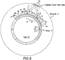
- FIG. 5 depicts aspects of the acoustic tool 10 steering an acoustic beam along the borehole wall.
- the term "steering” relates to moving the focal point of the acoustic beam using only one set of acoustic transducers (e.g., transducers T1-8) as illustrated in FIG. 5 .
- the acoustic beam is formed from the acoustic energy emitted from multiple transducers using various time delays. By changing the various time delays, the focal point can be moved to perform an acoustic measurement. The same various corresponding time delays may then be used to construct the return acoustic beam reflected off the borehole wall using the same transducers.
- the distance between adjacent steered focal due to acoustic steering is D2.
- both acoustic beam scanning and acoustic beam steering are used together to increase the resolution of the acoustic measurements as illustrated in FIG. 6 .
- an acoustic beam is moved a distance D1 for each acoustic measurement by scanning. This may be described as a plurality of acoustic beams with each beam performing an acoustic measurement.
- the distance D1 may depend on the size of each transducer, the number of transducers, and the spacing between transducers.
- the resolution of the measurements may then be increased by performing acoustic measurements by acoustic beam steering between the measurements performed by acoustic beam scanning.
- the distance between the acoustic measurements performed by acoustic beam steering is D2.
- a focal point area of the steered acoustic beam measurements may overlap (e.g., by 50%) the area of the scanned acoustic beam measurement.
- the distance D2 is less than the distance D1 so that the steered acoustic measurements are performed between the scanned acoustic measurements and may include overlapping.
- FIG. 7 depicts aspects of acoustic beamforming using one set of transducers in the array 11.
- FIG. 7A illustrates aspects of forming one acoustic beam using six acoustic transducers. The dotted line represents the time delay function for transmitting acoustic energy from each transducer.
- FIG. 7B illustrates aspects of forming three simultaneous acoustic beams from the same six acoustic transducers. Here, the dotted lines represent the time delay function for each acoustic beam.
- the excitation signal to trigger the transmission of acoustic energy for each transducer is the sum of the three excitation signals of the three individual acoustic beams. It can be appreciated that the three simultaneous acoustic beams depicted in FIG. 7B may have propagation directions that are parallel (or close to parallel) to each other and may thus be referred to as parallel beams.
- One advantage to using parallel or simultaneous beams is that they may be used to correct for side-lobes of the main or center beam.
- Side lobe beams are generated from the edges of the transducer element and project in a different direction from the main beam.
- the echoes of the side-lobes are much weaker than those of the main beam but if a very strong reflector is encountered they may be strong enough on returning to the transducer to be displayed prominently on the image. Because any returning echoes may be assumed by the machine to have been generated from the main beam, their position on the display can be incorrect (although at the right depth as time taken to and from transducer is the same).
- Correction for side-lobe beams can be implemented by transmitting only the main center beam, but receiving simultaneously three or more separate beams (i.e., main beam plus at least two side-lobe beams) using a phased array of acoustic transducers.
- One beam is reflected back from the direction of the main beam.
- the other beams due to the side-lobes which might be symmetric with respect to each other about the main beam, are reflected back along a direction having an angle with respect to the main beam.
- the angle of a side-lobe may be determined by testing or calibration of the tool.
- the correction is thus implemented by subtracting the energy or signals of the reflected side-lobe beams from that of the main beam.
- the simultaneous synthesis of several receive beams requires an independent delay and sum structure for each beam.
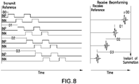
- FIG. 8 depicts aspects of time delays used to transmit and receive an acoustic beam using one set of acoustic transducers in the array.
- INN and INP relate to different transducer elements in a multi-element ultrasonic transducer.
- Transmit beamforming defines a focal point of the transmitted beam and may include for example transmit trigger timing to phase emitted pressure waves from the multi-element ultrasound transducer.
- Receiveive beamforming defines the focal point of the received echo and may include for example phase alignment and summation of signals that are received at different times by the multi-element ultrasound transducer.
- FIG. 9 is a simplified schematic diagram depicting aspects of one embodiment for transmitting and receiving acoustic energy using the array of acoustic transducers.
- the T/R switch is a switch for transmitting or receiving acoustic energy using the array of acoustic transducers.
- the receiver includes an amplifier for amplifying the analog signal to the ADC (analog to digital converter) for providing a digital signal having measurement data that may be transmitted uphole such as to the surface.
- ADC analog to digital converter
- FIG. 10 is one embodiment of a timing diagram depicting aspects of timing related to transmit beamforming and receive beamforming.
- FPGA is a field programmable gate array and DSP is a digital signal processor.
- Data transfer from the acquisition FPGA to the DSP is approximately 68.26 ⁇ s @ 30 MHz.
- the DSP processes acquired data #1 from the first transducer in about 52 ⁇ s after data transfer from the FPGA.
- FIG. 11 is a signal flow diagram depicting aspects of receiving acoustic echoes from the borehole wall, processing the received echoes, and transmitting processed data to the surface of the earth.
- LVDS relates to low voltage differential signaling.
- FIR filter is a finite impulse response filter.
- FIG. 12 depicts aspects of beam scanning the borehole wall using three separate acoustic beams formed by three separate groups of acoustic transducers where each group acts as a set of transducers as described above.
- three separate acoustic beams simultaneously scan and perform acoustic measurements of the borehole wall.
- beam steering is used to perform more acoustic measurements between the adjacent scanned acoustic beam measurement points to increase resolution before each of the three groups of transducers are shifted in the same direction. Spacing between the transducer sets is selected to minimize interference between the acoustic beams. It can be appreciated that two sets of transducers or more than three sets of transducers may be used to perform simultaneous acoustic measurements as long as the acoustic beams do not significantly interfere with each other.
- the downhole acoustic tool 10 may be calibrated by analysis or by testing in a laboratory or in the field.
- the testing may include disposing the tool in a borehole or simulated borehole of known geometry and performing acoustic measurements on one or more formation materials having known properties and with the borehole filled with a borehole fluid having known properties.
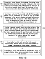
- FIG. 13 is a flow chart for a method 130 for imaging a wall of a borehole penetrating the earth.
- Block 131 calls for conveying a carrier through the borehole, the carrier having disposed thereon an array of acoustic transducers, the array of acoustic transducers being configured to at least one of transmit an acoustic signal toward the borehole wall and receive an acoustic return signal from the borehole wall.
- the array may be a circular linear array.
- Block 132 calls for scanning a section of the borehole wall with first acoustic beams that are transmitted by a series of sets of acoustic transducers in the array to produce adjacent first acoustic measurements that are spaced a first distance D1 apart along the borehole wall, each set having at least one transducer that is different from an adjacent set.
- each set in the series forms an acoustic beam that impinges on the borehole wall at a focal point area.
- the focal point areas are separated by a distance D1.
- Block 133 calls for steering a second acoustic beam along the section of the borehole wall using one set of acoustic transducers in the array to produce adjacent second acoustic measurements that are a second distance D2 apart from each other along the borehole wall, wherein the second acoustic measurements are between adjacent first acoustic measurements. Steering moves the focal point area using the same set of acoustic transducers. The second distance D2 is less than the first distance D1 in order to increase resolution.
- Block 134 calls for imaging the borehole wall using the first acoustic measurements and the second acoustic measurements to produce a borehole wall image using a processor.
- Block 135 calls for transmitting a signal that includes the borehole wall image to a signal receiving device using an output interface coupled to the processor.
- the method may include displaying the image on a display, printing the image, or recording the image using a digital or analog format.
- the image may be created by plotting the values of each measurement versus azimuth to create an image line and then stacking the image lines to image a depth interval.
- the measurement values may be represented by a shade in grayscale or some other color scale or by a range of colors and shades.
- the method 130 may also include correcting for an acoustic side-lobe of a transmitted acoustic beam of interest such as by measuring a reflected signal in the direction of the acoustic side-lobe and subtracting the reflected signal from a measured reflected signal in the direction of the acoustic beam of interest.
- the method 130 may also include generating a compound spatial image as the borehole image by averaging measurement values used to generate an image that are obtained from the same focal point from N different steered angles.
- the method 130 may also include imaging the borehole wall for 360 degrees by scanning a plurality of sections of the borehole wall with the first acoustic beams and steering the second acoustic beam along the plurality of sections.
- the method 130 may also include operating the array by dividing the array into a plurality of groups of transducers and operating the groups simultaneously, wherein the array of acoustic transducers is disposed circumferentially around the carrier. Additionally, the method 130 may include rotationally shifting the groups in a same direction to image the borehole for 360 degrees. The groups may be shifted simultaneously in order to increase logging speed.
- the method 130 may also include measuring time-of-flight of the first acoustic beams for the first acoustic measurements and measuring time-of-flight of the second acoustic beam for the second acoustic measurements. Alternatively or in addition, the method 130 may also include measuring amplitude of reflected or return first acoustic beams for the first acoustic measurements and measuring amplitude of reflected or return second acoustic beams for the second acoustic measurements.
- the method 130 may also include generating multiple acoustic beams with a circular linear phased of transducers by transmitting and receiving parallel beams from the same aperture and within the same transmit-receive time frame.
- multiple simultaneous beams may be transmitted and received using multiple apertures during the same transmit-receive time frame.
- the method 130 may also include simplified beam steering by alternating between an odd and even number of transducer elements within a transmit-receive aperture.
- the method 130 may also include generating a compound spatial image by averaging the images (i.e., measurement values used to generate the image) obtained from the same focal point from N different steered angles.
- one or more active array apertures can be activated simultaneously, each with two or more parallel transmit and/or receive beam patterns.
- a single transmit aperture can be divided into three receive apertures to receive from three different scan positions.
- Each receive aperture may be formed with a receive channel having the time delays adjusted to focus on three desired scan positions, therefore three scan positions can be acquired within the time of a single transmit/receive frame.
- Each element in the transmit aperture can be excited at the same time to create a single naturally focused beam field, with all of the focusing done on receive, or each element of the transmit aperture can be excited with a pulse train to create a focused transmit beam at each of the desired scan positions.
- Another advantage is that the resolution and therefore accuracy of borehole characterization can be increased due to the combination of acoustic beam scanning and acoustic beam steering.
- Yet another advantage is that the influence of side-lobes on transmitted acoustic beams can be reduced or eliminated such as by subtracting a measured reflected signal in the direction of a side-lobe from a measured reflected signal in the direction of a main beam or beam of interest.
- various analysis components may be used, including a digital and/or an analog system.
- the downhole electronics 8 or the computer processing system 9 may include digital and/or analog systems.
- the system may have components such as a processor, storage media, memory, input, output, communications link (wired, wireless, pulsed mud, optical or other), user interfaces, software programs, signal processors (digital or analog) and other such components (such as resistors, capacitors, inductors and others) to provide for operation and analyses of the apparatus and methods disclosed herein in any of several manners well-appreciated in the art.
- the signal receiving device may be memory or a storage medium. It can be appreciated that storing the result in memory or the storage medium will transform the memory or storage medium into a new state (containing the result) from a prior state (not containing the result). Further, an alert signal may be transmitted from the processor to a user interface if the result exceeds a threshold value.
- a power supply e.g., at least one of a generator, a remote supply and a battery
- cooling component heating component
- controller optical unit, electrical unit or electromechanical unit
- carrier means any device, device component, combination of devices, media and/or member that may be used to convey, house, support or otherwise facilitate the use of another device, device component, combination of devices, media and/or member.
- Other exemplary non-limiting carriers include drill strings of the coiled tube type, of the jointed pipe type and any combination or portion thereof.
- Other carrier examples include casing pipes, wirelines, wireline sondes, slickline sondes, drop shots, bottom-hole-assemblies, drill string inserts, modules, internal housings and substrate portions thereof.
Landscapes
- Engineering & Computer Science (AREA)
- Physics & Mathematics (AREA)
- Remote Sensing (AREA)
- Radar, Positioning & Navigation (AREA)
- General Physics & Mathematics (AREA)
- Computer Networks & Wireless Communication (AREA)
- Life Sciences & Earth Sciences (AREA)
- Geology (AREA)
- Acoustics & Sound (AREA)
- Mining & Mineral Resources (AREA)
- Geophysics (AREA)
- General Life Sciences & Earth Sciences (AREA)
- Environmental & Geological Engineering (AREA)
- Fluid Mechanics (AREA)
- Geochemistry & Mineralogy (AREA)
- Multimedia (AREA)
- Investigating Or Analyzing Materials By The Use Of Ultrasonic Waves (AREA)
- Measurement Of Velocity Or Position Using Acoustic Or Ultrasonic Waves (AREA)
- Length Measuring Devices Characterised By Use Of Acoustic Means (AREA)
Claims (12)
- Vorrichtung zum Abbilden einer Wand eines Bohrlochs (2), das in die Erde (3) eindringt, wobei die Vorrichtung Folgendes umfasst:einen Träger (5), der dazu eingerichtet ist, durch das Bohrloch (2) befördert zu werden;eine Anordnung (11) von akustischen Wandlern (12), die auf dem Träger (5) angeordnet und dazu eingerichtet sind, ein akustisches Signal in Richtung der Bohrlochwand zu übertragen und ein akustisches Rücksignal von der Bohrlochwand zu empfangen;eine Steuerung, die dazu eingerichtet ist, (i) einen Abschnitt der Bohrlochwand mit ersten akustischen Strahlen, die von einer Reihe von Sätzen von akustischen Wandlern (12) in der Anordnung (11) übertragen werden, abzutasten, um zueinander benachbarte erste akustische Messungen zu erzeugen, die entlang der Bohrlochwand voneinander um einen ersten Abstand D1 beabstandet sind, wobei jeder Satz mindestens einen Wandler aufweist, der sich von einem benachbarten Satz unterscheidet, (ii) einen zweiten akustischen Strahl unter Verwendung eines Satzes von akustischen Wandlern (12) in der Anordnung entlang des Abschnitts der Bohrlochwand (11) zu lenken, um zueinander benachbarte zweite akustische Messungen zu erzeugen, die entlang der Bohrlochwand voneinander um einen zweiten Abstand D2 beabstandet sind, und (iii) die Bohrlochwand unter Verwendung der ersten akustischen Messungen und der zweiten akustischen Messungen zum Erzeugen eines Bohrlochwandbildes abzubilden, wobei die zweiten akustischen Messungen ein Bild von Punkten der Bohrlochwand bilden, die zwischen zueinander benachbarten Punkten der Bohrlochwand, die von den ersten akustischen Messungen abgebildet wurden, liegen; undeine Ausgabeschnittstelle, die mit der Steuerung gekoppelt und dazu eingerichtet ist, ein das Bohrlochwandbild umfassendes Signal an eine Signalempfangsvorrichtung zu übertragen.
- Vorrichtung nach Anspruch 1, wobei die Steuerung ferner dazu eingerichtet ist, eine akustische Nebenkeule eines übertragenen akustischen Strahls von Interesse durch Messen eines reflektierten Signals in Richtung der akustischen Nebenkeule und Subtrahieren des reflektierten Signals von einem gemessenen reflektierten Signal in Richtung des akustischen Strahls von Interesse zu korrigieren.
- Vorrichtung nach Anspruch 1, wobei die Steuerung dazu eingerichtet ist, ein zusammengesetztes räumliches Bild durch Mitteln von zum Erzeugen eines Bildes verwendeten Messwerten, die vom gleichen Brennpunkt aus N verschiedenen gelenkten Winkeln erhalten wurden, zu erzeugen.
- Vorrichtung nach Anspruch 1, wobei die Steuerung ferner dazu eingerichtet ist, die Bohrlochwand über 360 Grad abzubilden, indem eine Vielzahl von Abschnitten der Bohrlochwand mit den ersten akustischen Strahlen abgetastet werden und der zweite akustische Strahl entlang der Vielzahl von Abschnitten gelenkt wird.
- Vorrichtung nach Anspruch 1, wobei die Anordnung (11) von akustischen Wandlern (12) umlaufend um den Träger (5) angeordnet ist und die Steuerung ferner dazu eingerichtet ist, die Anordnung (11) durch Teilen der Anordnung (11) in eine Vielzahl von Gruppen von Wandlern und gleichzeitiges Betreiben der Gruppen zu betreiben.
- Vorrichtung nach Anspruch 5, wobei die Steuerung ferner dazu eingerichtet ist, die Gruppen zum Abbilden des Bohrlochs (2) über 360 Grad gleichzeitig in eine gleiche Richtung drehend zu versetzen.
- Vorrichtung nach Anspruch 1, wobei die Anordnung (11) mehrere Anordnungen umfasst und die Steuerung ferner dazu eingerichtet ist, die mehreren Anordnungen gleichzeitig zu betreiben.
- Vorrichtung nach Anspruch 1, wobei
ein Brennpunkt der zweiten akustischen Messungen einen Brennpunkt der ersten akustischen Messungen überlappt. - Verfahren (130) zum Abbilden einer Wand eines Bohrlochs (2), das in die Erde (3) eindringt, wobei das Verfahren (130) Folgendes umfasst:Befördern eines Trägers (5) durch das Bohrloch (2), wobei auf dem Träger (5) eine Anordnung (11) von akustischen Wandlern (12) angeordnet ist, wobei die Anordnung (11) von akustischen Wandlern (12) dazu eingerichtet ist, ein akustisches Signal in Richtung der Bohrlochwand zu übertragen und ein akustisches Rücksignal von der Bohrlochwand zu empfangen;Abtasten eines Abschnitts der Bohrlochwand mit ersten akustischen Strahlen, die von einer Reihe von Sätzen von akustischen Wandlern (12) in der Anordnung (11) übertragen werden, um zueinander benachbarte erste akustische Messungen zu erzeugen, die entlang der Bohrlochwand voneinander um einen ersten Abstand D1 beabstandet sind, wobei jeder Satz mindestens einen Wandler aufweist, der sich von einem benachbarten Satz unterscheidet; unter Verwendung eines Satzes von akustischen Wandlern (12) in der Anordnung Lenken eines zweiten akustischen Strahls entlang des Abschnitts der Bohrlochwand (11), um zueinander benachbarte zweite akustische Messungen zu erzeugen, die entlang der Bohrlochwand voneinander um einen zweiten Abstand D2 beabstandet sind, wobei die zweiten akustischen Messungen ein Bild von Punkten der Bohrlochwand bilden, die zwischen zueinander benachbarten Punkten der Bohrlochwand, die von den ersten akustischen Messungen abgebildet wurden, liegen;Abbilden der Bohrlochwand unter Verwendung der ersten akustischen Messungen und der zweiten akustischen Messungen, um ein Bohrlochwandbild unter Verwendung eines Prozessors zu erzeugen; undÜbertragen eines das Bohrlochwandbild umfassenden Signals an eine Signalempfangsvorrichtung unter Verwendung einer mit dem Prozessor gekoppelten Ausgabeschnittstelle.
- Verfahren (130) nach Anspruch 9, ferner umfassend das Korrigieren einer akustischen Nebenkeule eines übertragenen akustischen Strahls von Interesse durch Messen eines reflektierten Signals in Richtung der akustischen Nebenkeule
und Subtrahieren des reflektierten Signals von einem gemessenen reflektierten Signal in Richtung des akustischen Strahls von Interesse. - Verfahren (130) nach Anspruch 9, ferner umfassend das Betreiben der Anordnung (11) durch Teilen der Anordnung (11) in eine Vielzahl von Gruppen von Wandlern und gleichzeitiges Betreiben der Gruppen, wobei die Anordnung (11) von akustischen Wandlern (12) umlaufend um den Träger (5) angeordnet ist.
- Verfahren (130) nach Anspruch 11, ferner umfassend das gleichzeitige drehende Versetzen der Gruppen in eine gleiche Richtung, um das Bohrloch (2) über 360 Grad abzubilden.
Applications Claiming Priority (2)
| Application Number | Priority Date | Filing Date | Title |
|---|---|---|---|
| US14/567,912 US9784874B2 (en) | 2014-12-11 | 2014-12-11 | Multi-beam phased array acoustic transducer operation for downhole applications |
| PCT/US2015/063227 WO2016094132A1 (en) | 2014-12-11 | 2015-12-01 | Multi-beam phased array acoustic transducer operation for downhole applications |
Publications (3)
| Publication Number | Publication Date |
|---|---|
| EP3230558A1 EP3230558A1 (de) | 2017-10-18 |
| EP3230558A4 EP3230558A4 (de) | 2018-08-29 |
| EP3230558B1 true EP3230558B1 (de) | 2022-08-24 |
Family
ID=56107957
Family Applications (1)
| Application Number | Title | Priority Date | Filing Date |
|---|---|---|---|
| EP15866748.5A Active EP3230558B1 (de) | 2014-12-11 | 2015-12-01 | Betrieb eines mehrstrahligen phasengesteuerten akustischen wandlers für bohrlochanwendungen |
Country Status (5)
| Country | Link |
|---|---|
| US (1) | US9784874B2 (de) |
| EP (1) | EP3230558B1 (de) |
| BR (1) | BR112017012055B1 (de) |
| SA (1) | SA517381690B1 (de) |
| WO (1) | WO2016094132A1 (de) |
Families Citing this family (13)
| Publication number | Priority date | Publication date | Assignee | Title |
|---|---|---|---|---|
| EP2540957A1 (de) * | 2011-06-30 | 2013-01-02 | Welltec A/S | Bohrlochwerkzeug zur Bestimmung von Seitenkanälen |
| GB2601942B (en) * | 2015-06-17 | 2022-09-14 | Darkvision Tech Inc | Ultrasonic imaging device and method for wells |
| WO2017127041A1 (en) * | 2016-01-20 | 2017-07-27 | Halliburton Energy Services, Inc. | Systems and methods for correcting off-center acoustic sondes |
| US10392919B2 (en) * | 2016-03-23 | 2019-08-27 | Baker Hughes, A Ge Company, Llc | Simulated core sample estimated from composite borehole measurement |
| US10061050B2 (en) * | 2016-08-08 | 2018-08-28 | Gowell International, Llc | Fractal magnetic sensor array using mega matrix decomposition method for downhole application |
| BR112019007120A2 (pt) * | 2016-11-09 | 2019-07-02 | Halliburton Energy Services Inc | método implementado por processador e sistema |
| EP3385725A1 (de) | 2017-04-04 | 2018-10-10 | Nederlandse Organisatie voor toegepast- natuurwetenschappelijk onderzoek TNO | Verfahren und atomkraftmikroskopiesystem zur durchführung von unteroberflächenabbildung |
| US10739318B2 (en) * | 2017-04-19 | 2020-08-11 | Baker Hughes, A Ge Company, Llc | Detection system including sensors and method of operating such |
| US10605944B2 (en) | 2017-06-23 | 2020-03-31 | Baker Hughes, A Ge Company, Llc | Formation acoustic property measurement with beam-angled transducer array |
| US20190346334A1 (en) * | 2018-05-10 | 2019-11-14 | Rhediant, Inc. | Pipeline pig for generation of acoustic waveforms |
| GB2578123B8 (en) * | 2018-10-16 | 2021-08-11 | Darkvision Tech Inc | Overlapped scheduling and sorting for acoustic transducer pulses |
| US11726224B2 (en) * | 2019-01-24 | 2023-08-15 | Baker Hughes, A Ge Company, Llc | B annulus acoustic pressure sensing |
| US20240084695A1 (en) * | 2022-09-09 | 2024-03-14 | Saudi Arabian Oil Company | Casing deformation monitoring |
Family Cites Families (9)
| Publication number | Priority date | Publication date | Assignee | Title |
|---|---|---|---|---|
| US4867264A (en) | 1986-09-17 | 1989-09-19 | Atlantic Richfield Company | Apparatus and method for investigating wellbores and the like |
| JPH10127634A (ja) * | 1996-11-06 | 1998-05-19 | Aloka Co Ltd | 超音波診断装置 |
| EP1348954A1 (de) * | 2002-03-28 | 2003-10-01 | Services Petroliers Schlumberger | Vorrichtung und Verfahren zur akustischen Untersuchung eines Bohrlochs mit Hilfe eines phasengesteuerten Ultraschall-Gruppenwandlers |
| WO2005024462A1 (en) | 2003-09-10 | 2005-03-17 | Koninklijke Philips Electronics, N.V. | Ultrasonic spatial compounding with multiple simultaneous beam transmission |
| KR100954988B1 (ko) * | 2006-09-26 | 2010-04-29 | 주식회사 메디슨 | 초음파 영상을 형성하는 초음파 시스템 및 방법 |
| US9110179B2 (en) | 2010-11-12 | 2015-08-18 | Chevron U.S.A. Inc. | Integrated system for investigating sub-surface features of a rock formation |
| US8627715B2 (en) * | 2011-01-24 | 2014-01-14 | Intelligent Sciences, Ltd. | Imaging subsurface formations while wellbore drilling using beam steering for improved image resolution |
| US8894580B2 (en) * | 2012-04-27 | 2014-11-25 | Ut-Battelle, Llc | Reflective echo tomographic imaging using acoustic beams |
| US9260958B2 (en) | 2012-12-20 | 2016-02-16 | Schlumberger Technology Corporation | System and method for acoustic imaging using a transducer array |
-
2014
- 2014-12-11 US US14/567,912 patent/US9784874B2/en active Active
-
2015
- 2015-12-01 WO PCT/US2015/063227 patent/WO2016094132A1/en not_active Ceased
- 2015-12-01 BR BR112017012055-0A patent/BR112017012055B1/pt active IP Right Grant
- 2015-12-01 EP EP15866748.5A patent/EP3230558B1/de active Active
-
2017
- 2017-06-08 SA SA517381690A patent/SA517381690B1/ar unknown
Also Published As
| Publication number | Publication date |
|---|---|
| US9784874B2 (en) | 2017-10-10 |
| BR112017012055B1 (pt) | 2022-07-05 |
| US20160170063A1 (en) | 2016-06-16 |
| EP3230558A1 (de) | 2017-10-18 |
| WO2016094132A1 (en) | 2016-06-16 |
| BR112017012055A2 (pt) | 2018-01-16 |
| SA517381690B1 (ar) | 2022-07-19 |
| EP3230558A4 (de) | 2018-08-29 |
Similar Documents
| Publication | Publication Date | Title |
|---|---|---|
| EP3230558B1 (de) | Betrieb eines mehrstrahligen phasengesteuerten akustischen wandlers für bohrlochanwendungen | |
| EP3862796B1 (de) | Echtzeitrekonfiguration phasengesteuerter array-operationen | |
| EP3250784B1 (de) | Vorrichtungen und verfahren zur akustischen bohrlochbilderzeugung | |
| US11899153B2 (en) | Guided mode beamforming for probing open-hole and cased-hole well environments | |
| US20200033494A1 (en) | Through tubing cement evaluation using seismic methods | |
| US9103196B2 (en) | Pipelined pulse-echo scheme for an acoustic image tool for use downhole | |
| US7350568B2 (en) | Logging a well | |
| EP2577358B1 (de) | Vorrichtung und verfahren zur erzeugung eines kollimierten schallenergiestrahls in einem bohrloch | |
| US20100095757A1 (en) | Measurements of rock parameters | |
| EP2577357B1 (de) | Vorrichtung und verfahren zur erzeugung eines kollimierten schallenergiestrahls in einem bohrloch | |
| NO324764B1 (no) | Akustisk system for maling under boring, med anvendelse av flere segmenterte sendere og mottakere | |
| NO348332B1 (en) | Correcting for Eccentricity of Acoustic Sensors in Wells and Pipes | |
| SG186152A1 (en) | Device and method for generating a collimated beam of acoustic energy in a borehole | |
| US9534492B2 (en) | Pressure compensated capacitive micromachined ultrasound transducer for downhole applications | |
| GB2578697A (en) | Formation acoustic property measurement with beam-angled transducer array | |
| EP1592988B1 (de) | Signalverarbeitung von array-daten einer akustischen bohrlochapparatur | |
| CN101122228A (zh) | 一种井下前视相控声波成像方法及成像装置 | |
| CN100349016C (zh) | 向井外地层中扫描辐射二维声场的方法 | |
| US20070070811A1 (en) | Multiple tracks scanning tool | |
| CA2185412A1 (en) | Method and apparatus for borehole acoustic reflection logging | |
| CN102921623A (zh) | 一种相控圆弧阵声波辐射器 |
Legal Events
| Date | Code | Title | Description |
|---|---|---|---|
| STAA | Information on the status of an ep patent application or granted ep patent |
Free format text: STATUS: THE INTERNATIONAL PUBLICATION HAS BEEN MADE |
|
| PUAI | Public reference made under article 153(3) epc to a published international application that has entered the european phase |
Free format text: ORIGINAL CODE: 0009012 |
|
| STAA | Information on the status of an ep patent application or granted ep patent |
Free format text: STATUS: REQUEST FOR EXAMINATION WAS MADE |
|
| 17P | Request for examination filed |
Effective date: 20170707 |
|
| AK | Designated contracting states |
Kind code of ref document: A1 Designated state(s): AL AT BE BG CH CY CZ DE DK EE ES FI FR GB GR HR HU IE IS IT LI LT LU LV MC MK MT NL NO PL PT RO RS SE SI SK SM TR |
|
| AX | Request for extension of the european patent |
Extension state: BA ME |
|
| RIN1 | Information on inventor provided before grant (corrected) |
Inventor name: SULE, VAIBHAV Inventor name: CHATTERJEE, KAMALESH Inventor name: STEINSIEK, ROGER, R. Inventor name: ZHAO, JINSONG Inventor name: LEGGETT, JAMES, V. |
|
| DAV | Request for validation of the european patent (deleted) | ||
| DAX | Request for extension of the european patent (deleted) | ||
| RIC1 | Information provided on ipc code assigned before grant |
Ipc: G01V 1/50 20060101ALI20180718BHEP Ipc: G01S 7/524 20060101ALI20180718BHEP Ipc: G01S 15/88 20060101ALI20180718BHEP Ipc: G01V 1/40 20060101ALI20180718BHEP Ipc: G01S 7/52 20060101AFI20180718BHEP Ipc: G10K 11/34 20060101ALI20180718BHEP Ipc: G01S 7/526 20060101ALI20180718BHEP Ipc: E21B 47/00 20120101ALI20180718BHEP Ipc: G01S 15/89 20060101ALI20180718BHEP |
|
| A4 | Supplementary search report drawn up and despatched |
Effective date: 20180726 |
|
| STAA | Information on the status of an ep patent application or granted ep patent |
Free format text: STATUS: EXAMINATION IS IN PROGRESS |
|
| 17Q | First examination report despatched |
Effective date: 20210319 |
|
| REG | Reference to a national code |
Ref country code: DE Ref legal event code: R079 Ref document number: 602015080513 Country of ref document: DE Free format text: PREVIOUS MAIN CLASS: E21B0047000000 Ipc: G01S0007520000 |
|
| RIC1 | Information provided on ipc code assigned before grant |
Ipc: G01V 1/50 20060101ALI20211119BHEP Ipc: G01V 1/40 20060101ALI20211119BHEP Ipc: G10K 11/34 20060101ALI20211119BHEP Ipc: G01S 15/89 20060101ALI20211119BHEP Ipc: G01S 15/88 20060101ALI20211119BHEP Ipc: G01S 7/526 20060101ALI20211119BHEP Ipc: G01S 7/524 20060101ALI20211119BHEP Ipc: G01S 7/52 20060101AFI20211119BHEP |
|
| GRAP | Despatch of communication of intention to grant a patent |
Free format text: ORIGINAL CODE: EPIDOSNIGR1 |
|
| STAA | Information on the status of an ep patent application or granted ep patent |
Free format text: STATUS: GRANT OF PATENT IS INTENDED |
|
| INTG | Intention to grant announced |
Effective date: 20220602 |
|
| GRAS | Grant fee paid |
Free format text: ORIGINAL CODE: EPIDOSNIGR3 |
|
| GRAA | (expected) grant |
Free format text: ORIGINAL CODE: 0009210 |
|
| STAA | Information on the status of an ep patent application or granted ep patent |
Free format text: STATUS: THE PATENT HAS BEEN GRANTED |
|
| AK | Designated contracting states |
Kind code of ref document: B1 Designated state(s): AL AT BE BG CH CY CZ DE DK EE ES FI FR GB GR HR HU IE IS IT LI LT LU LV MC MK MT NL NO PL PT RO RS SE SI SK SM TR |
|
| RAP3 | Party data changed (applicant data changed or rights of an application transferred) |
Owner name: BAKER HUGHES HOLDINGS LLC |
|
| REG | Reference to a national code |
Ref country code: CH Ref legal event code: EP |
|
| REG | Reference to a national code |
Ref country code: IE Ref legal event code: FG4D |
|
| REG | Reference to a national code |
Ref country code: AT Ref legal event code: REF Ref document number: 1514025 Country of ref document: AT Kind code of ref document: T Effective date: 20220915 Ref country code: DE Ref legal event code: R096 Ref document number: 602015080513 Country of ref document: DE |
|
| REG | Reference to a national code |
Ref country code: NO Ref legal event code: T2 Effective date: 20220824 |
|
| REG | Reference to a national code |
Ref country code: LT Ref legal event code: MG9D |
|
| REG | Reference to a national code |
Ref country code: NL Ref legal event code: MP Effective date: 20220824 |
|
| PG25 | Lapsed in a contracting state [announced via postgrant information from national office to epo] |
Ref country code: SE Free format text: LAPSE BECAUSE OF FAILURE TO SUBMIT A TRANSLATION OF THE DESCRIPTION OR TO PAY THE FEE WITHIN THE PRESCRIBED TIME-LIMIT Effective date: 20220824 Ref country code: RS Free format text: LAPSE BECAUSE OF FAILURE TO SUBMIT A TRANSLATION OF THE DESCRIPTION OR TO PAY THE FEE WITHIN THE PRESCRIBED TIME-LIMIT Effective date: 20220824 Ref country code: PT Free format text: LAPSE BECAUSE OF FAILURE TO SUBMIT A TRANSLATION OF THE DESCRIPTION OR TO PAY THE FEE WITHIN THE PRESCRIBED TIME-LIMIT Effective date: 20221226 Ref country code: NL Free format text: LAPSE BECAUSE OF FAILURE TO SUBMIT A TRANSLATION OF THE DESCRIPTION OR TO PAY THE FEE WITHIN THE PRESCRIBED TIME-LIMIT Effective date: 20220824 Ref country code: LV Free format text: LAPSE BECAUSE OF FAILURE TO SUBMIT A TRANSLATION OF THE DESCRIPTION OR TO PAY THE FEE WITHIN THE PRESCRIBED TIME-LIMIT Effective date: 20220824 Ref country code: LT Free format text: LAPSE BECAUSE OF FAILURE TO SUBMIT A TRANSLATION OF THE DESCRIPTION OR TO PAY THE FEE WITHIN THE PRESCRIBED TIME-LIMIT Effective date: 20220824 Ref country code: FI Free format text: LAPSE BECAUSE OF FAILURE TO SUBMIT A TRANSLATION OF THE DESCRIPTION OR TO PAY THE FEE WITHIN THE PRESCRIBED TIME-LIMIT Effective date: 20220824 Ref country code: ES Free format text: LAPSE BECAUSE OF FAILURE TO SUBMIT A TRANSLATION OF THE DESCRIPTION OR TO PAY THE FEE WITHIN THE PRESCRIBED TIME-LIMIT Effective date: 20220824 |
|
| REG | Reference to a national code |
Ref country code: AT Ref legal event code: MK05 Ref document number: 1514025 Country of ref document: AT Kind code of ref document: T Effective date: 20220824 |
|
| PG25 | Lapsed in a contracting state [announced via postgrant information from national office to epo] |
Ref country code: PL Free format text: LAPSE BECAUSE OF FAILURE TO SUBMIT A TRANSLATION OF THE DESCRIPTION OR TO PAY THE FEE WITHIN THE PRESCRIBED TIME-LIMIT Effective date: 20220824 Ref country code: IS Free format text: LAPSE BECAUSE OF FAILURE TO SUBMIT A TRANSLATION OF THE DESCRIPTION OR TO PAY THE FEE WITHIN THE PRESCRIBED TIME-LIMIT Effective date: 20221224 Ref country code: HR Free format text: LAPSE BECAUSE OF FAILURE TO SUBMIT A TRANSLATION OF THE DESCRIPTION OR TO PAY THE FEE WITHIN THE PRESCRIBED TIME-LIMIT Effective date: 20220824 Ref country code: GR Free format text: LAPSE BECAUSE OF FAILURE TO SUBMIT A TRANSLATION OF THE DESCRIPTION OR TO PAY THE FEE WITHIN THE PRESCRIBED TIME-LIMIT Effective date: 20221125 |
|
| PG25 | Lapsed in a contracting state [announced via postgrant information from national office to epo] |
Ref country code: SM Free format text: LAPSE BECAUSE OF FAILURE TO SUBMIT A TRANSLATION OF THE DESCRIPTION OR TO PAY THE FEE WITHIN THE PRESCRIBED TIME-LIMIT Effective date: 20220824 Ref country code: RO Free format text: LAPSE BECAUSE OF FAILURE TO SUBMIT A TRANSLATION OF THE DESCRIPTION OR TO PAY THE FEE WITHIN THE PRESCRIBED TIME-LIMIT Effective date: 20220824 Ref country code: DK Free format text: LAPSE BECAUSE OF FAILURE TO SUBMIT A TRANSLATION OF THE DESCRIPTION OR TO PAY THE FEE WITHIN THE PRESCRIBED TIME-LIMIT Effective date: 20220824 Ref country code: CZ Free format text: LAPSE BECAUSE OF FAILURE TO SUBMIT A TRANSLATION OF THE DESCRIPTION OR TO PAY THE FEE WITHIN THE PRESCRIBED TIME-LIMIT Effective date: 20220824 Ref country code: AT Free format text: LAPSE BECAUSE OF FAILURE TO SUBMIT A TRANSLATION OF THE DESCRIPTION OR TO PAY THE FEE WITHIN THE PRESCRIBED TIME-LIMIT Effective date: 20220824 |
|
| REG | Reference to a national code |
Ref country code: DE Ref legal event code: R097 Ref document number: 602015080513 Country of ref document: DE |
|
| PG25 | Lapsed in a contracting state [announced via postgrant information from national office to epo] |
Ref country code: SK Free format text: LAPSE BECAUSE OF FAILURE TO SUBMIT A TRANSLATION OF THE DESCRIPTION OR TO PAY THE FEE WITHIN THE PRESCRIBED TIME-LIMIT Effective date: 20220824 Ref country code: EE Free format text: LAPSE BECAUSE OF FAILURE TO SUBMIT A TRANSLATION OF THE DESCRIPTION OR TO PAY THE FEE WITHIN THE PRESCRIBED TIME-LIMIT Effective date: 20220824 |
|
| PG25 | Lapsed in a contracting state [announced via postgrant information from national office to epo] |
Ref country code: AL Free format text: LAPSE BECAUSE OF FAILURE TO SUBMIT A TRANSLATION OF THE DESCRIPTION OR TO PAY THE FEE WITHIN THE PRESCRIBED TIME-LIMIT Effective date: 20220824 |
|
| PLBE | No opposition filed within time limit |
Free format text: ORIGINAL CODE: 0009261 |
|
| STAA | Information on the status of an ep patent application or granted ep patent |
Free format text: STATUS: NO OPPOSITION FILED WITHIN TIME LIMIT |
|
| REG | Reference to a national code |
Ref country code: DE Ref legal event code: R119 Ref document number: 602015080513 Country of ref document: DE |
|
| P01 | Opt-out of the competence of the unified patent court (upc) registered |
Effective date: 20230526 |
|
| REG | Reference to a national code |
Ref country code: CH Ref legal event code: PL |
|
| 26N | No opposition filed |
Effective date: 20230525 |
|
| REG | Reference to a national code |
Ref country code: BE Ref legal event code: MM Effective date: 20221231 |
|
| PG25 | Lapsed in a contracting state [announced via postgrant information from national office to epo] |
Ref country code: SI Free format text: LAPSE BECAUSE OF FAILURE TO SUBMIT A TRANSLATION OF THE DESCRIPTION OR TO PAY THE FEE WITHIN THE PRESCRIBED TIME-LIMIT Effective date: 20220824 Ref country code: LU Free format text: LAPSE BECAUSE OF NON-PAYMENT OF DUE FEES Effective date: 20221201 |
|
| PG25 | Lapsed in a contracting state [announced via postgrant information from national office to epo] |
Ref country code: LI Free format text: LAPSE BECAUSE OF NON-PAYMENT OF DUE FEES Effective date: 20221231 Ref country code: IE Free format text: LAPSE BECAUSE OF NON-PAYMENT OF DUE FEES Effective date: 20221201 Ref country code: DE Free format text: LAPSE BECAUSE OF NON-PAYMENT OF DUE FEES Effective date: 20230701 Ref country code: CH Free format text: LAPSE BECAUSE OF NON-PAYMENT OF DUE FEES Effective date: 20221231 |
|
| PG25 | Lapsed in a contracting state [announced via postgrant information from national office to epo] |
Ref country code: FR Free format text: LAPSE BECAUSE OF NON-PAYMENT OF DUE FEES Effective date: 20221231 Ref country code: BE Free format text: LAPSE BECAUSE OF NON-PAYMENT OF DUE FEES Effective date: 20221231 |
|
| PG25 | Lapsed in a contracting state [announced via postgrant information from national office to epo] |
Ref country code: HU Free format text: LAPSE BECAUSE OF FAILURE TO SUBMIT A TRANSLATION OF THE DESCRIPTION OR TO PAY THE FEE WITHIN THE PRESCRIBED TIME-LIMIT; INVALID AB INITIO Effective date: 20151201 |
|
| PG25 | Lapsed in a contracting state [announced via postgrant information from national office to epo] |
Ref country code: CY Free format text: LAPSE BECAUSE OF FAILURE TO SUBMIT A TRANSLATION OF THE DESCRIPTION OR TO PAY THE FEE WITHIN THE PRESCRIBED TIME-LIMIT Effective date: 20220824 |
|
| PG25 | Lapsed in a contracting state [announced via postgrant information from national office to epo] |
Ref country code: MK Free format text: LAPSE BECAUSE OF FAILURE TO SUBMIT A TRANSLATION OF THE DESCRIPTION OR TO PAY THE FEE WITHIN THE PRESCRIBED TIME-LIMIT Effective date: 20220824 Ref country code: IT Free format text: LAPSE BECAUSE OF FAILURE TO SUBMIT A TRANSLATION OF THE DESCRIPTION OR TO PAY THE FEE WITHIN THE PRESCRIBED TIME-LIMIT Effective date: 20220824 |
|
| PG25 | Lapsed in a contracting state [announced via postgrant information from national office to epo] |
Ref country code: MC Free format text: LAPSE BECAUSE OF FAILURE TO SUBMIT A TRANSLATION OF THE DESCRIPTION OR TO PAY THE FEE WITHIN THE PRESCRIBED TIME-LIMIT Effective date: 20220824 |
|
| PG25 | Lapsed in a contracting state [announced via postgrant information from national office to epo] |
Ref country code: MC Free format text: LAPSE BECAUSE OF FAILURE TO SUBMIT A TRANSLATION OF THE DESCRIPTION OR TO PAY THE FEE WITHIN THE PRESCRIBED TIME-LIMIT Effective date: 20220824 |
|
| PG25 | Lapsed in a contracting state [announced via postgrant information from national office to epo] |
Ref country code: BG Free format text: LAPSE BECAUSE OF FAILURE TO SUBMIT A TRANSLATION OF THE DESCRIPTION OR TO PAY THE FEE WITHIN THE PRESCRIBED TIME-LIMIT Effective date: 20220824 |
|
| PG25 | Lapsed in a contracting state [announced via postgrant information from national office to epo] |
Ref country code: MT Free format text: LAPSE BECAUSE OF FAILURE TO SUBMIT A TRANSLATION OF THE DESCRIPTION OR TO PAY THE FEE WITHIN THE PRESCRIBED TIME-LIMIT Effective date: 20220824 |
|
| PG25 | Lapsed in a contracting state [announced via postgrant information from national office to epo] |
Ref country code: TR Free format text: LAPSE BECAUSE OF FAILURE TO SUBMIT A TRANSLATION OF THE DESCRIPTION OR TO PAY THE FEE WITHIN THE PRESCRIBED TIME-LIMIT Effective date: 20220824 |
|
| PGFP | Annual fee paid to national office [announced via postgrant information from national office to epo] |
Ref country code: GB Payment date: 20251119 Year of fee payment: 11 |
|
| PGFP | Annual fee paid to national office [announced via postgrant information from national office to epo] |
Ref country code: NO Payment date: 20251121 Year of fee payment: 11 |