EP3230578B1 - Magnetventil für einen kraftstoffinjektor - Google Patents
Magnetventil für einen kraftstoffinjektor Download PDFInfo
- Publication number
- EP3230578B1 EP3230578B1 EP15798010.3A EP15798010A EP3230578B1 EP 3230578 B1 EP3230578 B1 EP 3230578B1 EP 15798010 A EP15798010 A EP 15798010A EP 3230578 B1 EP3230578 B1 EP 3230578B1
- Authority
- EP
- European Patent Office
- Prior art keywords
- spring
- control valve
- solenoid control
- flexible element
- valve
- Prior art date
- Legal status (The legal status is an assumption and is not a legal conclusion. Google has not performed a legal analysis and makes no representation as to the accuracy of the status listed.)
- Active
Links
Images



Classifications
-
- F—MECHANICAL ENGINEERING; LIGHTING; HEATING; WEAPONS; BLASTING
- F02—COMBUSTION ENGINES; HOT-GAS OR COMBUSTION-PRODUCT ENGINE PLANTS
- F02M—SUPPLYING COMBUSTION ENGINES IN GENERAL WITH COMBUSTIBLE MIXTURES OR CONSTITUENTS THEREOF
- F02M47/00—Fuel-injection apparatus operated cyclically with fuel-injection valves actuated by fluid pressure
- F02M47/02—Fuel-injection apparatus operated cyclically with fuel-injection valves actuated by fluid pressure of accumulator-injector type, i.e. having fuel pressure of accumulator tending to open, and fuel pressure in other chamber tending to close, injection valves and having means for periodically releasing that closing pressure
- F02M47/027—Electrically actuated valves draining the chamber to release the closing pressure
-
- F—MECHANICAL ENGINEERING; LIGHTING; HEATING; WEAPONS; BLASTING
- F02—COMBUSTION ENGINES; HOT-GAS OR COMBUSTION-PRODUCT ENGINE PLANTS
- F02M—SUPPLYING COMBUSTION ENGINES IN GENERAL WITH COMBUSTIBLE MIXTURES OR CONSTITUENTS THEREOF
- F02M63/00—Other fuel-injection apparatus having pertinent characteristics not provided for in groups F02M39/00 - F02M57/00 or F02M67/00; Details, component parts, or accessories of fuel-injection apparatus, not provided for in, or of interest apart from, the apparatus of groups F02M39/00 - F02M61/00 or F02M67/00; Combination of fuel pump with other devices, e.g. lubricating oil pump
- F02M63/0012—Valves
- F02M63/0014—Valves characterised by the valve actuating means
- F02M63/0015—Valves characterised by the valve actuating means electrical, e.g. using solenoid
- F02M63/0017—Valves characterised by the valve actuating means electrical, e.g. using solenoid using electromagnetic operating means
-
- F—MECHANICAL ENGINEERING; LIGHTING; HEATING; WEAPONS; BLASTING
- F16—ENGINEERING ELEMENTS AND UNITS; GENERAL MEASURES FOR PRODUCING AND MAINTAINING EFFECTIVE FUNCTIONING OF MACHINES OR INSTALLATIONS; THERMAL INSULATION IN GENERAL
- F16K—VALVES; TAPS; COCKS; ACTUATING-FLOATS; DEVICES FOR VENTING OR AERATING
- F16K31/00—Actuating devices; Operating means; Releasing devices
- F16K31/02—Actuating devices; Operating means; Releasing devices electric; magnetic
- F16K31/06—Actuating devices; Operating means; Releasing devices electric; magnetic using a magnet, e.g. diaphragm valves, cutting off by means of a liquid
- F16K31/0686—Braking, pressure equilibration, shock absorbing
-
- F—MECHANICAL ENGINEERING; LIGHTING; HEATING; WEAPONS; BLASTING
- F02—COMBUSTION ENGINES; HOT-GAS OR COMBUSTION-PRODUCT ENGINE PLANTS
- F02M—SUPPLYING COMBUSTION ENGINES IN GENERAL WITH COMBUSTIBLE MIXTURES OR CONSTITUENTS THEREOF
- F02M2200/00—Details of fuel-injection apparatus, not otherwise provided for
- F02M2200/30—Fuel-injection apparatus having mechanical parts, the movement of which is damped
- F02M2200/306—Fuel-injection apparatus having mechanical parts, the movement of which is damped using mechanical means
-
- F—MECHANICAL ENGINEERING; LIGHTING; HEATING; WEAPONS; BLASTING
- F02—COMBUSTION ENGINES; HOT-GAS OR COMBUSTION-PRODUCT ENGINE PLANTS
- F02M—SUPPLYING COMBUSTION ENGINES IN GENERAL WITH COMBUSTIBLE MIXTURES OR CONSTITUENTS THEREOF
- F02M2200/00—Details of fuel-injection apparatus, not otherwise provided for
- F02M2200/50—Arrangements of springs for valves used in fuel injectors or fuel injection pumps
Definitions
- the invention relates to a solenoid valve for controlling a fuel injector and more particularly to the spring of said solenoid valve.
- a fuel injector conventionally comprises a needle controlled opening and closing depending on the pressure differential between a control chamber and the injection nozzle.
- the pressure is a function of the position of a two-way control solenoid valve, or an on-off valve, switching between an open position when energized and a closed position when not in use. 'is not.
- the solenoid valve When the solenoid valve is in the closed position, the high-pressure fuel enters the control chamber and urges the needle to the closed position prohibiting the injection of fuel and, when the solenoid valve switches to the open position the fuel previously held prisoner.
- the control chamber can exit via a discharge channel allowing the pressure in the control chamber to decrease and then the needle to move to the open position for fuel injection.
- the solenoid valve comprises a coil, a magnetic armature and a spring.
- the armature moves by compressing the spring and, when the coil is no longer energized, the spring pushes the armature back to its original position.
- the armature is secured to a valve stem sliding in a hydraulic bore, the movements of the rod in the bore allowing or not the flow of fuel to flow.
- the spring is typically a compression spring with non-contiguous helical turns arranged in the center of the coil and protruding from it so as to come to urge the armature.
- a known spring length 10 mm, outer diameter 2 mm, wire diameter of about 0.5 mm and about 15 turns has a stiffness in compression of about 40 N / mm and in operation it is installed with a pre-charge of the order 35 N and is biased several hundred Hertz, its relative compression in operation not exceeding 40 microns.
- Such a solenoid valve is shown for example in the document EP 0 957 262 A .
- this solenoid valve for controlling a fuel injector.
- this solenoid valve comprises a coil adapted to be driven by a central control unit, the coil generating a magnetic field when it is energized, and a frame-rod assembly comprising a magnetic armature adapted to be attracted by the magnetic field, and a valve stem adapted to slide in a hydraulic distributor bore, the armature and the rod being fixed to each other.
- the solenoid valve further comprises an elastic device designed to move the armature-rod assembly when the coil is not energized.
- this elastic device is a spring arranged in a housing provided in the center of the coil, the spring protruding slightly from said coil to press against one end of the valve stem and away from the coil when the latter is not powered.
- the present invention is distinguished by the fact that the elastic device comprises the complementary arrangement of a compression spring with helical turns and another flexible element integral with the spring. Said other flexible element being capable of interrupting the propagation of compressions and detents waves in the spring. This advantageous characteristic makes it possible to avoid the disturbances of the movements of the armature-rod assembly, disturbances related to compression and relaxation of the spring.
- said other flexible element is an overmoulding of at least a portion of the spring.
- Said overmolding can occupy several inter-turns spaces of the spring or even, it can coat all the spring.
- the overmoulding occupies a tubular cylindrical space enveloping the spring and retaining a free central space.
- only the spring wire is embedded by said other flexible member. This specific coating can be achieved even before the wire is wound to form the spring.
- said other flexible element is an independent piece inserted in the center of the spring.
- said independent piece is a resilient cylinder radially compressed against the turns of the spring so as to be secured.
- the elastic cylinder can be stretched to reduce the section and thus insert it into the heart of the spring. By releasing it the cylinder tries to recover its form at rest but remains compressed against the inside of the turns.
- said other flexible element is an elastic tube in the center of which is inserted a rod radially deforming said tube so as to apply it integrally against the turns of the spring.
- said other flexible element is a cylinder threaded at the same pitch as the pitch of the turns of the spring, said other flexible element can be screwed to the center of the spring (66) so as to become integral.
- said other flexible element may be of elastomer based on rubber, for example fluoroelastomer.
- the invention also extends to a fuel injector provided with a solenoid valve made according to any of the aforementioned modes.
- the figure 1 is a longitudinal section of an injector 10 extending along a main axis A1, shown vertically in the conventional and nonlimiting sense of the figure.
- a main axis A1 shown vertically in the conventional and nonlimiting sense of the figure.
- the arbitrary orientation of the figure 1 will be used and so terms such as "up, down, above or below, vertical " may be used without limiting the description or scope of the invention.
- the injector 10 comprises a tubular body 12 substantially cylindrical and made of several sections rigidly fixed to each other and extending axially from an injector head 14, at the top of the figure, to a nozzle 16 of which end is provided with injection holes 18.
- the injector head 14 comprises an inlet mouth 20, an outlet mouth 22 and an electrical connector 24 adapted to receive another connector, not shown, for connecting the injector 10 to a control unit.
- the injector is provided with a solenoid valve 26, more detailed by the figure 2 , extending along a valve axis A2 parallel to the main axis A1.
- the solenoid valve 26 comprises an electric coil 28 whose winding is molded and provided at its center with a blind bore 30 in which is housed a valve spring 32 compressed between the bottom of the bore 30 and a frame-rod assembly 34 arranged just opposite the coil 28.
- the armature-rod assembly 34 is composed of the rigid assembly of a magnetic armature 36, having the shape of a transverse thick disk in the center of which is encased and crimped a valve stem 38 extending downward from an upper end 40 flush slightly above the upper face 42 of the armature 36, said upper face 42 facing the coil 28, to a lower end 44 remote from the face 36 of the frame 36.
- the valve stem 38 is arranged in a right-sliding fit in a hydraulic distributor bore 48.
- the injector represented on the figure 1 and on which this description is based is only a non-limiting example and, many alternatives of constructions exist and may be mentioned however, the alternatives that would be omitted can not be excluded from the scope conferred by the claims.
- the main axis A1 and the valve axis A2 are distinct and parallel. This misalignment introduced in the patent EP1693563 has many advantages but is not imperative and injectors in which the two axes are confused exist and can benefit from the teachings of the present invention.
- connection means 50 such as rigid or flexible cables extending vertically in a specific conduit provided in the injector body 12.
- the nozzle 16, arranged under the solenoid valve 26, mainly comprises a needle 52 arranged sliding in a bore and hydraulically controlled as a function of the pressure difference between the two ends of the needle 52.
- the needle 52 so called by the Professionals with reference to its general shape, is an elongate cylindrical shaft extending from a needle head 54 to a conical tip 56 defining a needle seat 58.
- the needle head 54 opens into a control chamber 60 while the conical tip 56 cooperates with a face of the body 12 so as to allow or prohibit the injection of fuel via the injection holes 18.
- the injector 10 is also provided with a high pressure circuit 62 extending into the body 12 between the inlet mouth 20 and the injection holes 18, the high pressure circuit 62 also supplying the control chamber 60 and, a low pressure return circuit 64 extending from the control chamber 60 to the outlet mouth 22 through which fuel can return to a low pressure tank.
- the coil 28 is not powered. It does not generate a magnetic field.
- the armature-rod assembly 34 is pushed down into a closed position PFV by the valve spring 32. High pressure fuel is trapped in the control chamber 60 and the high pressure in said control chamber 60 generates on the needle head 54 a closing force which keeps the needle 52 in the closed position PFA, or low position in which the fuel injection is prohibited.
- the coil 28 is energized and generates a magnetic field which attracts the armature 36 so that the armature-rod assembly 34 approaches the coil 28 in an open position POV and compresses the spring 32.
- fuel previously trapped in the control chamber 60 can escape to the return circuit 64.
- the displacements of the armature rod assembly 34 can reach a frequency of several hundreds of Hertz, for an amplitude of the order of 30 ⁇ m while the fuel pressure in the high pressure circuit 62 may be several thousand bars.
- the latter comprises a metal core forming a helical spring 66 proper and a other flexible element 68.
- the coil spring 66 is a compression spring with non-contiguous turns whose wire has a diameter of the order of 0.5 mm.
- Said other flexible element 68 is an overmolding of the coil spring 66 made of a rubber-based elastomer.
- a preferred material will for example be selected from the family of fluoroelastomers for the known qualities of temperature resistance and chemical resistance, as well as for their strong adhesion to metal son.
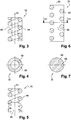
- the figure 3 is a longitudinal section of the spring assembly 32 and the overmolding 68 is made so that the elastomer forms a tube in the wall of which is included the spring 66.
- the molding operation has allowed the elastomer to fit between the turns of the spring 66 and occupy the space.
- the figure 4 is a transverse section for observing the tubular section of the overmolding preserving an empty central part. A small section of the spring wire 66 that emerges in the section plane is shown.
- the overmolding is performed so as to extend axially from one end to the other of the spring 66.
- the spring 66 being entirely included in the thickness of the tubular wall of the overmolding 68 elastomer.
- overmoulding may extend only over part of the turns of the spring 66, leaving the other turns free of elastomer.
- This partial overmolding of the spring 66 can find very varied shapes such as the overmoulding of several neighboring turns or, the overmolding of several non-neighboring turns thus forming two distinct overmolded zones.
- Overmolding 68 may also be performed around a small area only of the spring 66 comprising only one or two turns.
- Overmoulding Figures 3 and 4 leave an empty part in the center of the spring, here taking the form of a cylinder.
- the size of this empty part can easily be chosen so that the overmolding envelops only the spring 66, or this part can be reduced, the overmoulding 68 forming a thicker wall tube, the central cylinder having smaller diameter.
- FIG 8 is shown a spring 66 in the heart of which has been made overmolding 68 which is perceived that the material has partially inserted between the turns of the spring 66.
- FIG 9 there is shown a second embodiment in which the wire has been coated with rubber-based elastomer before being wound and shaped into a spring.
- the coating is made so that a turn is in contact with neighboring turns. A thinner coating leaving a gap between each adjacent turn is also possible.
- This third mode differs from the previous in that the rubber-based elastomer is added without being overmoulded on the spring wire.
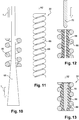
- the figure 10 illustrates the placement of an elastomer cylinder in the center of the spring.
- the elastic cylinder 68 At rest, the elastic cylinder 68 has a cross section greater than that available in the center of the spring 66.
- the cylinder 68 is then stretched, according to the opposite arrows T, so as to reduce the section and thus be able to insert it in the heart turns of the spring 66.
- the traction force T is then released and the cylinder naturally tries to resume its rest form but, due to a lack of space in the heart of the spring, it remains radially compressed against the turns of the spring such as according to the figure 11 .
- the assembly comprising the spring 66 and the elastic cylinder 68 forms an integral assembly deforming in use in compressions and relaxes.
- FIG. 12 and 13 there is shown a fourth embodiment in which, like the third embodiment, the elastomer is added without being overmolded.
- the elastomer 68 forms a tubular piece which is freely inserted in the center of the spring 66.
- a rod 70 is inserted in force in the center of the elastic tube 68.
- This forced insertion radially deforms the elastic tube 68, according to the figure 13 , by increasing its section so that the outer face of the tube is pressed against the wire of the spring 66 and locally matches the shape of the wire and is inserted slightly between each turn.
- the assembly comprising the spring 66, the elastomeric tube 68 and the rod 70 form an integral assembly deforming in use in compressions and relaxes.
- the elastomer insert 68 is made, independently of the metal spring 66, as a threaded piece that can be inserted by screwing complementary to the heart of the spring.
- the figure shows the two parts before assembly. According to what will be desired during the development of the injector, the insert can be screwed over the entire length of the spring 66 or, a shorter insert will be screwed on only part of the length of the spring for example half or three quarters.
Landscapes
- Engineering & Computer Science (AREA)
- General Engineering & Computer Science (AREA)
- Mechanical Engineering (AREA)
- Physics & Mathematics (AREA)
- Chemical & Material Sciences (AREA)
- Combustion & Propulsion (AREA)
- Electromagnetism (AREA)
- Fluid Mechanics (AREA)
- Fuel-Injection Apparatus (AREA)
Claims (11)
- Steuermagnetventil (26) eines Kraftstoffinjektors (10), wobei das Magnetventil (26) enthält:- eine Spule (28), die dazu ausgelegt ist, unter Stromversorgung von einer zentralen Steuereinheit angesteuert zu werden, wobei die Spule (28) ein Magnetfeld erzeugt, wenn sie mit Strom versorgt wird,- eine Anker-Schaft-Anordnung (34) mit einem Magnetanker (36), der dazu ausgelegt ist, von dem Magnetfeld angezogen zu werden, und mit einem Ventilschaft (38), der dazu ausgelegt ist, in einer hydraulischen Verteilerbohrung (48) zu gleiten, wobei der Anker (36) und der Schaft (38) aneinander befestigt sind, und- eine elastische Vorrichtung (32), die dazu vorgesehen ist, die Anker-Schaft-Anordnung (34) dann zu verlagern, wenn die Spule (28) nicht mit Strom versorgt wird,dadurch gekennzeichnet, dass
die elastische Vorrichtung (32) die komplementäre, fest verbundene Anordnung von einer Druckfeder (66) mit Spiralwindungen und von einem weiteren nachgiebigen Element (68) enthält, das fest mit der Feder (66) verbunden ist, wobei das weitere nachgiebige Element (68) so beschaffen ist, dass es die Ausbreitung von Kompressions- und Entspannungswellen in der Feder (66) unterbricht. - Steuermagnetventil (26) nach dem vorangehenden Anspruch, wobei das weitere nachgiebige Element (68) eine Anformung zumindest eines Teils der Feder (66) ist.
- Steuermagnetventil (26) nach Anspruch 2, wobei die Anformung die gesamte Feder (66) ummantelt.
- Steuermagnetventil (26) nach Anspruch 2, wobei die Anformung einen zylinderrohrförmigen Raum einnimmt, der die Feder (66) umhüllt und einen mittigen Freiraum beibehält.
- Steuermagnetventil (26) nach einem der Ansprüche 2 bis 4, wobei die Anformung einen voll ausgeführten zylindrischen Raum ohne mittigen Freiraum einnimmt.
- Steuermagnetventil (26) nach Anspruch 2, wobei die Anformung nur den Metalldraht der Feder (66) ummantelt.
- Steuermagnetventil (26) nach Anspruch 1, wobei das weitere nachgiebige Element (68) ein elastischer Zylinder ist, der in die Mitte der Feder eingeführt ist und radial an die Windungen der Feder (66) so gedrückt wird, dass er fest damit verbunden ist.
- Steuermagnetventil (26) nach Anspruch 1, wobei das weitere nachgiebige Element (68) ein elastisches Rohr ist, das in die Mitte der Feder eingeführt ist und in dessen Mitte ein Schaft (70) eingeführt ist, der das Rohr (68) radial so verformt, dass es radial so zusammengedrückt wird, dass es fest an die Windungen der Feder (66) angebunden ist.
- Steuermagnetventil (26) nach Anspruch 1, wobei das weitere nachgiebige Element (68) ein Gewindezylinder ist, der in die Mitte der Feder (66) eingeschraubt werden kann, so dass er fest damit verbunden wird.
- Steuermagnetventil (26) nach einem der vorangehenden Ansprüche, wobei das weitere nachgiebige Element (68) aus Elastomer auf Basis von Kautschuk besteht, das ein Fluorelastomer sein kann.
- Kraftstoffinjektor (10) mit einem Magnetventil (26), das nach einem der vorangehenden Ansprüche hergestellt ist.
Applications Claiming Priority (2)
| Application Number | Priority Date | Filing Date | Title |
|---|---|---|---|
| FR1462176A FR3030009B1 (fr) | 2014-12-10 | 2014-12-10 | Electrovanne d'injecteur de carburant |
| PCT/EP2015/076872 WO2016091544A1 (fr) | 2014-12-10 | 2015-11-17 | Electrovanne d'injecteur de carburant |
Publications (2)
| Publication Number | Publication Date |
|---|---|
| EP3230578A1 EP3230578A1 (de) | 2017-10-18 |
| EP3230578B1 true EP3230578B1 (de) | 2018-10-24 |
Family
ID=53269544
Family Applications (1)
| Application Number | Title | Priority Date | Filing Date |
|---|---|---|---|
| EP15798010.3A Active EP3230578B1 (de) | 2014-12-10 | 2015-11-17 | Magnetventil für einen kraftstoffinjektor |
Country Status (3)
| Country | Link |
|---|---|
| EP (1) | EP3230578B1 (de) |
| FR (1) | FR3030009B1 (de) |
| WO (1) | WO2016091544A1 (de) |
Families Citing this family (1)
| Publication number | Priority date | Publication date | Assignee | Title |
|---|---|---|---|---|
| GB2567002A (en) * | 2017-09-30 | 2019-04-03 | Delphi Int Operations Luxembourg Sarl | Spring assembly operating in liquid |
Family Cites Families (4)
| Publication number | Priority date | Publication date | Assignee | Title |
|---|---|---|---|---|
| SE513766C2 (sv) * | 1998-03-13 | 2000-10-30 | Alfa Laval Ab | Stödanordning för en king en rotationsaxel roterbar spindel som uppbär en centrifugrotor |
| GB9810208D0 (en) * | 1998-05-13 | 1998-07-08 | Lucas Ind Plc | Fuel injector |
| US7422193B2 (en) * | 2005-08-31 | 2008-09-09 | Emerson Electric Co. | Solenoid valve |
| DE102010064105A1 (de) * | 2010-12-23 | 2012-01-19 | Robert Bosch Gmbh | Ventil zum Einspritzen von Kraftstoff |
-
2014
- 2014-12-10 FR FR1462176A patent/FR3030009B1/fr not_active Expired - Fee Related
-
2015
- 2015-11-17 EP EP15798010.3A patent/EP3230578B1/de active Active
- 2015-11-17 WO PCT/EP2015/076872 patent/WO2016091544A1/fr not_active Ceased
Non-Patent Citations (1)
| Title |
|---|
| None * |
Also Published As
| Publication number | Publication date |
|---|---|
| WO2016091544A1 (fr) | 2016-06-16 |
| EP3230578A1 (de) | 2017-10-18 |
| FR3030009B1 (fr) | 2017-07-14 |
| FR3030009A1 (fr) | 2016-06-17 |
Similar Documents
| Publication | Publication Date | Title |
|---|---|---|
| FR2781529A1 (fr) | Injecteur de carburant equipe d'une soupape de commande amont et procede de realisation | |
| CH684033A5 (fr) | Vanne à écoulement proportionnel. | |
| WO2003089364A1 (fr) | Bec de remplissage a commande electromagnetique | |
| FR2466630A1 (fr) | Injecteur a actionnement electromagnetique, pour moteurs a combustion interne | |
| FR2954449A1 (fr) | Soupape electromagnetique et procede de fabrication de l'induit d'une telle soupape | |
| EP3230578B1 (de) | Magnetventil für einen kraftstoffinjektor | |
| FR2933748A1 (fr) | Dispositif injecteur de carburant | |
| FR2982327A1 (fr) | Ensemble de bouchon pour vanne haute pression | |
| EP2910767B1 (de) | Kraftstoffeinspritzventil | |
| EP1126962A1 (de) | Verfahren zur herstellung eines verschlusses, stössel und einen derartigen verschluss enthaltender ausgabekopf | |
| EP3449114B1 (de) | Kraftstoffinjektor | |
| FR2955170A1 (fr) | Robinet de gaz et bouteille de gaz sous pression comportant un tel robinet | |
| EP0467823B1 (de) | Elektromagnetisches Ventil zur Durchflussregelung | |
| EP3344867B1 (de) | Kraftstoffinjektor mit externer einstellung der schraubenfeder | |
| FR3024499A1 (fr) | Actionneur a double ressort | |
| CH665264A5 (fr) | Electrovalve a plusieurs debits. | |
| FR2989460A1 (fr) | Capteur de temperature | |
| EP3507482B1 (de) | Spulenanordnung | |
| FR3017685A1 (fr) | Systeme d'electroaimants poly-entrefers pour soupape electromagnetique, notamment pour injecteur de carburant dans un moteur a propulsion thermique | |
| EP2640959A1 (de) | Druckregler und kraftstoffversorgungsvorrichtung mit einem derartigen regler | |
| WO2017157730A1 (fr) | Injecteur de carburant | |
| BE527395A (de) | ||
| FR2878985A1 (fr) | Reducteur de pression equilibre | |
| WO2023031572A1 (fr) | Actionneur électromagnétique à entrainement direct et amortissement amélioré | |
| EP3489505B1 (de) | Ventilnadel eines injektors |
Legal Events
| Date | Code | Title | Description |
|---|---|---|---|
| PUAI | Public reference made under article 153(3) epc to a published international application that has entered the european phase |
Free format text: ORIGINAL CODE: 0009012 |
|
| 17P | Request for examination filed |
Effective date: 20170710 |
|
| AK | Designated contracting states |
Kind code of ref document: A1 Designated state(s): AL AT BE BG CH CY CZ DE DK EE ES FI FR GB GR HR HU IE IS IT LI LT LU LV MC MK MT NL NO PL PT RO RS SE SI SK SM TR |
|
| AX | Request for extension of the european patent |
Extension state: BA ME |
|
| DAV | Request for validation of the european patent (deleted) | ||
| DAX | Request for extension of the european patent (deleted) | ||
| GRAP | Despatch of communication of intention to grant a patent |
Free format text: ORIGINAL CODE: EPIDOSNIGR1 |
|
| INTG | Intention to grant announced |
Effective date: 20180508 |
|
| GRAS | Grant fee paid |
Free format text: ORIGINAL CODE: EPIDOSNIGR3 |
|
| GRAA | (expected) grant |
Free format text: ORIGINAL CODE: 0009210 |
|
| AK | Designated contracting states |
Kind code of ref document: B1 Designated state(s): AL AT BE BG CH CY CZ DE DK EE ES FI FR GB GR HR HU IE IS IT LI LT LU LV MC MK MT NL NO PL PT RO RS SE SI SK SM TR |
|
| REG | Reference to a national code |
Ref country code: CH Ref legal event code: EP |
|
| REG | Reference to a national code |
Ref country code: IE Ref legal event code: FG4D Free format text: LANGUAGE OF EP DOCUMENT: FRENCH |
|
| REG | Reference to a national code |
Ref country code: AT Ref legal event code: REF Ref document number: 1056947 Country of ref document: AT Kind code of ref document: T Effective date: 20181115 |
|
| REG | Reference to a national code |
Ref country code: DE Ref legal event code: R096 Ref document number: 602015018818 Country of ref document: DE |
|
| REG | Reference to a national code |
Ref country code: NL Ref legal event code: MP Effective date: 20181024 |
|
| REG | Reference to a national code |
Ref country code: LT Ref legal event code: MG4D |
|
| REG | Reference to a national code |
Ref country code: AT Ref legal event code: MK05 Ref document number: 1056947 Country of ref document: AT Kind code of ref document: T Effective date: 20181024 |
|
| PG25 | Lapsed in a contracting state [announced via postgrant information from national office to epo] |
Ref country code: NL Free format text: LAPSE BECAUSE OF FAILURE TO SUBMIT A TRANSLATION OF THE DESCRIPTION OR TO PAY THE FEE WITHIN THE PRESCRIBED TIME-LIMIT Effective date: 20181024 |
|
| PG25 | Lapsed in a contracting state [announced via postgrant information from national office to epo] |
Ref country code: BG Free format text: LAPSE BECAUSE OF FAILURE TO SUBMIT A TRANSLATION OF THE DESCRIPTION OR TO PAY THE FEE WITHIN THE PRESCRIBED TIME-LIMIT Effective date: 20190124 Ref country code: NO Free format text: LAPSE BECAUSE OF FAILURE TO SUBMIT A TRANSLATION OF THE DESCRIPTION OR TO PAY THE FEE WITHIN THE PRESCRIBED TIME-LIMIT Effective date: 20190124 Ref country code: PL Free format text: LAPSE BECAUSE OF FAILURE TO SUBMIT A TRANSLATION OF THE DESCRIPTION OR TO PAY THE FEE WITHIN THE PRESCRIBED TIME-LIMIT Effective date: 20181024 Ref country code: HR Free format text: LAPSE BECAUSE OF FAILURE TO SUBMIT A TRANSLATION OF THE DESCRIPTION OR TO PAY THE FEE WITHIN THE PRESCRIBED TIME-LIMIT Effective date: 20181024 Ref country code: AT Free format text: LAPSE BECAUSE OF FAILURE TO SUBMIT A TRANSLATION OF THE DESCRIPTION OR TO PAY THE FEE WITHIN THE PRESCRIBED TIME-LIMIT Effective date: 20181024 Ref country code: IS Free format text: LAPSE BECAUSE OF FAILURE TO SUBMIT A TRANSLATION OF THE DESCRIPTION OR TO PAY THE FEE WITHIN THE PRESCRIBED TIME-LIMIT Effective date: 20190224 Ref country code: ES Free format text: LAPSE BECAUSE OF FAILURE TO SUBMIT A TRANSLATION OF THE DESCRIPTION OR TO PAY THE FEE WITHIN THE PRESCRIBED TIME-LIMIT Effective date: 20181024 Ref country code: LT Free format text: LAPSE BECAUSE OF FAILURE TO SUBMIT A TRANSLATION OF THE DESCRIPTION OR TO PAY THE FEE WITHIN THE PRESCRIBED TIME-LIMIT Effective date: 20181024 Ref country code: LV Free format text: LAPSE BECAUSE OF FAILURE TO SUBMIT A TRANSLATION OF THE DESCRIPTION OR TO PAY THE FEE WITHIN THE PRESCRIBED TIME-LIMIT Effective date: 20181024 Ref country code: FI Free format text: LAPSE BECAUSE OF FAILURE TO SUBMIT A TRANSLATION OF THE DESCRIPTION OR TO PAY THE FEE WITHIN THE PRESCRIBED TIME-LIMIT Effective date: 20181024 |
|
| PG25 | Lapsed in a contracting state [announced via postgrant information from national office to epo] |
Ref country code: AL Free format text: LAPSE BECAUSE OF FAILURE TO SUBMIT A TRANSLATION OF THE DESCRIPTION OR TO PAY THE FEE WITHIN THE PRESCRIBED TIME-LIMIT Effective date: 20181024 Ref country code: RS Free format text: LAPSE BECAUSE OF FAILURE TO SUBMIT A TRANSLATION OF THE DESCRIPTION OR TO PAY THE FEE WITHIN THE PRESCRIBED TIME-LIMIT Effective date: 20181024 Ref country code: SE Free format text: LAPSE BECAUSE OF FAILURE TO SUBMIT A TRANSLATION OF THE DESCRIPTION OR TO PAY THE FEE WITHIN THE PRESCRIBED TIME-LIMIT Effective date: 20181024 Ref country code: PT Free format text: LAPSE BECAUSE OF FAILURE TO SUBMIT A TRANSLATION OF THE DESCRIPTION OR TO PAY THE FEE WITHIN THE PRESCRIBED TIME-LIMIT Effective date: 20190224 Ref country code: GR Free format text: LAPSE BECAUSE OF FAILURE TO SUBMIT A TRANSLATION OF THE DESCRIPTION OR TO PAY THE FEE WITHIN THE PRESCRIBED TIME-LIMIT Effective date: 20190125 |
|
| REG | Reference to a national code |
Ref country code: DE Ref legal event code: R119 Ref document number: 602015018818 Country of ref document: DE |
|
| REG | Reference to a national code |
Ref country code: CH Ref legal event code: PL |
|
| PG25 | Lapsed in a contracting state [announced via postgrant information from national office to epo] |
Ref country code: IT Free format text: LAPSE BECAUSE OF FAILURE TO SUBMIT A TRANSLATION OF THE DESCRIPTION OR TO PAY THE FEE WITHIN THE PRESCRIBED TIME-LIMIT Effective date: 20181024 Ref country code: DK Free format text: LAPSE BECAUSE OF FAILURE TO SUBMIT A TRANSLATION OF THE DESCRIPTION OR TO PAY THE FEE WITHIN THE PRESCRIBED TIME-LIMIT Effective date: 20181024 Ref country code: LU Free format text: LAPSE BECAUSE OF NON-PAYMENT OF DUE FEES Effective date: 20181117 Ref country code: CZ Free format text: LAPSE BECAUSE OF FAILURE TO SUBMIT A TRANSLATION OF THE DESCRIPTION OR TO PAY THE FEE WITHIN THE PRESCRIBED TIME-LIMIT Effective date: 20181024 |
|
| REG | Reference to a national code |
Ref country code: BE Ref legal event code: MM Effective date: 20181130 |
|
| REG | Reference to a national code |
Ref country code: IE Ref legal event code: MM4A |
|
| PG25 | Lapsed in a contracting state [announced via postgrant information from national office to epo] |
Ref country code: MC Free format text: LAPSE BECAUSE OF FAILURE TO SUBMIT A TRANSLATION OF THE DESCRIPTION OR TO PAY THE FEE WITHIN THE PRESCRIBED TIME-LIMIT Effective date: 20181024 Ref country code: CH Free format text: LAPSE BECAUSE OF NON-PAYMENT OF DUE FEES Effective date: 20181130 Ref country code: LI Free format text: LAPSE BECAUSE OF NON-PAYMENT OF DUE FEES Effective date: 20181130 Ref country code: RO Free format text: LAPSE BECAUSE OF FAILURE TO SUBMIT A TRANSLATION OF THE DESCRIPTION OR TO PAY THE FEE WITHIN THE PRESCRIBED TIME-LIMIT Effective date: 20181024 Ref country code: SK Free format text: LAPSE BECAUSE OF FAILURE TO SUBMIT A TRANSLATION OF THE DESCRIPTION OR TO PAY THE FEE WITHIN THE PRESCRIBED TIME-LIMIT Effective date: 20181024 Ref country code: SM Free format text: LAPSE BECAUSE OF FAILURE TO SUBMIT A TRANSLATION OF THE DESCRIPTION OR TO PAY THE FEE WITHIN THE PRESCRIBED TIME-LIMIT Effective date: 20181024 Ref country code: EE Free format text: LAPSE BECAUSE OF FAILURE TO SUBMIT A TRANSLATION OF THE DESCRIPTION OR TO PAY THE FEE WITHIN THE PRESCRIBED TIME-LIMIT Effective date: 20181024 |
|
| PLBE | No opposition filed within time limit |
Free format text: ORIGINAL CODE: 0009261 |
|
| STAA | Information on the status of an ep patent application or granted ep patent |
Free format text: STATUS: NO OPPOSITION FILED WITHIN TIME LIMIT |
|
| 26N | No opposition filed |
Effective date: 20190725 |
|
| PG25 | Lapsed in a contracting state [announced via postgrant information from national office to epo] |
Ref country code: IE Free format text: LAPSE BECAUSE OF NON-PAYMENT OF DUE FEES Effective date: 20181117 Ref country code: SI Free format text: LAPSE BECAUSE OF FAILURE TO SUBMIT A TRANSLATION OF THE DESCRIPTION OR TO PAY THE FEE WITHIN THE PRESCRIBED TIME-LIMIT Effective date: 20181024 Ref country code: DE Free format text: LAPSE BECAUSE OF NON-PAYMENT OF DUE FEES Effective date: 20190601 |
|
| PG25 | Lapsed in a contracting state [announced via postgrant information from national office to epo] |
Ref country code: BE Free format text: LAPSE BECAUSE OF NON-PAYMENT OF DUE FEES Effective date: 20181130 |
|
| PG25 | Lapsed in a contracting state [announced via postgrant information from national office to epo] |
Ref country code: MT Free format text: LAPSE BECAUSE OF FAILURE TO SUBMIT A TRANSLATION OF THE DESCRIPTION OR TO PAY THE FEE WITHIN THE PRESCRIBED TIME-LIMIT Effective date: 20181024 |
|
| PG25 | Lapsed in a contracting state [announced via postgrant information from national office to epo] |
Ref country code: TR Free format text: LAPSE BECAUSE OF FAILURE TO SUBMIT A TRANSLATION OF THE DESCRIPTION OR TO PAY THE FEE WITHIN THE PRESCRIBED TIME-LIMIT Effective date: 20181024 |
|
| PG25 | Lapsed in a contracting state [announced via postgrant information from national office to epo] |
Ref country code: CY Free format text: LAPSE BECAUSE OF FAILURE TO SUBMIT A TRANSLATION OF THE DESCRIPTION OR TO PAY THE FEE WITHIN THE PRESCRIBED TIME-LIMIT Effective date: 20181024 Ref country code: HU Free format text: LAPSE BECAUSE OF FAILURE TO SUBMIT A TRANSLATION OF THE DESCRIPTION OR TO PAY THE FEE WITHIN THE PRESCRIBED TIME-LIMIT; INVALID AB INITIO Effective date: 20151117 Ref country code: MK Free format text: LAPSE BECAUSE OF NON-PAYMENT OF DUE FEES Effective date: 20181024 |
|
| GBPC | Gb: european patent ceased through non-payment of renewal fee |
Effective date: 20191117 |
|
| PG25 | Lapsed in a contracting state [announced via postgrant information from national office to epo] |
Ref country code: GB Free format text: LAPSE BECAUSE OF NON-PAYMENT OF DUE FEES Effective date: 20191117 |
|
| P01 | Opt-out of the competence of the unified patent court (upc) registered |
Effective date: 20230327 |
|
| PGFP | Annual fee paid to national office [announced via postgrant information from national office to epo] |
Ref country code: FR Payment date: 20251013 Year of fee payment: 11 |