EP3230607B1 - Joint sphérique - Google Patents
Joint sphérique Download PDFInfo
- Publication number
- EP3230607B1 EP3230607B1 EP15791302.1A EP15791302A EP3230607B1 EP 3230607 B1 EP3230607 B1 EP 3230607B1 EP 15791302 A EP15791302 A EP 15791302A EP 3230607 B1 EP3230607 B1 EP 3230607B1
- Authority
- EP
- European Patent Office
- Prior art keywords
- joint
- ball
- lubricant
- region
- profile ring
- Prior art date
- Legal status (The legal status is an assumption and is not a legal conclusion. Google has not performed a legal analysis and makes no representation as to the accuracy of the status listed.)
- Active
Links
Images

Classifications
-
- F—MECHANICAL ENGINEERING; LIGHTING; HEATING; WEAPONS; BLASTING
- F16—ENGINEERING ELEMENTS AND UNITS; GENERAL MEASURES FOR PRODUCING AND MAINTAINING EFFECTIVE FUNCTIONING OF MACHINES OR INSTALLATIONS; THERMAL INSULATION IN GENERAL
- F16C—SHAFTS; FLEXIBLE SHAFTS; ELEMENTS OR CRANKSHAFT MECHANISMS; ROTARY BODIES OTHER THAN GEARING ELEMENTS; BEARINGS
- F16C11/00—Pivots; Pivotal connections
- F16C11/04—Pivotal connections
- F16C11/06—Ball-joints; Other joints having more than one degree of angular freedom, i.e. universal joints
- F16C11/068—Special features relating to lubrication
-
- F—MECHANICAL ENGINEERING; LIGHTING; HEATING; WEAPONS; BLASTING
- F16—ENGINEERING ELEMENTS AND UNITS; GENERAL MEASURES FOR PRODUCING AND MAINTAINING EFFECTIVE FUNCTIONING OF MACHINES OR INSTALLATIONS; THERMAL INSULATION IN GENERAL
- F16C—SHAFTS; FLEXIBLE SHAFTS; ELEMENTS OR CRANKSHAFT MECHANISMS; ROTARY BODIES OTHER THAN GEARING ELEMENTS; BEARINGS
- F16C11/00—Pivots; Pivotal connections
- F16C11/04—Pivotal connections
- F16C11/06—Ball-joints; Other joints having more than one degree of angular freedom, i.e. universal joints
- F16C11/0619—Ball-joints; Other joints having more than one degree of angular freedom, i.e. universal joints the female part comprising a blind socket receiving the male part
- F16C11/0623—Construction or details of the socket member
- F16C11/0628—Construction or details of the socket member with linings
-
- F—MECHANICAL ENGINEERING; LIGHTING; HEATING; WEAPONS; BLASTING
- F16—ENGINEERING ELEMENTS AND UNITS; GENERAL MEASURES FOR PRODUCING AND MAINTAINING EFFECTIVE FUNCTIONING OF MACHINES OR INSTALLATIONS; THERMAL INSULATION IN GENERAL
- F16C—SHAFTS; FLEXIBLE SHAFTS; ELEMENTS OR CRANKSHAFT MECHANISMS; ROTARY BODIES OTHER THAN GEARING ELEMENTS; BEARINGS
- F16C11/00—Pivots; Pivotal connections
- F16C11/04—Pivotal connections
- F16C11/06—Ball-joints; Other joints having more than one degree of angular freedom, i.e. universal joints
- F16C11/08—Ball-joints; Other joints having more than one degree of angular freedom, i.e. universal joints with resilient bearings
- F16C11/083—Ball-joints; Other joints having more than one degree of angular freedom, i.e. universal joints with resilient bearings by means of parts of rubber or like materials
- F16C11/086—Ball-joints; Other joints having more than one degree of angular freedom, i.e. universal joints with resilient bearings by means of parts of rubber or like materials with an elastomeric member in the blind end of a socket
-
- F—MECHANICAL ENGINEERING; LIGHTING; HEATING; WEAPONS; BLASTING
- F16—ENGINEERING ELEMENTS AND UNITS; GENERAL MEASURES FOR PRODUCING AND MAINTAINING EFFECTIVE FUNCTIONING OF MACHINES OR INSTALLATIONS; THERMAL INSULATION IN GENERAL
- F16C—SHAFTS; FLEXIBLE SHAFTS; ELEMENTS OR CRANKSHAFT MECHANISMS; ROTARY BODIES OTHER THAN GEARING ELEMENTS; BEARINGS
- F16C11/00—Pivots; Pivotal connections
- F16C11/04—Pivotal connections
- F16C11/06—Ball-joints; Other joints having more than one degree of angular freedom, i.e. universal joints
- F16C11/0619—Ball-joints; Other joints having more than one degree of angular freedom, i.e. universal joints the female part comprising a blind socket receiving the male part
- F16C11/0623—Construction or details of the socket member
- F16C11/0652—Construction or details of the socket member combined with a damper other than elastic linings
Definitions
- the invention relates to a ball joint with a housing housing comprising a joint housing, a joint ball comprehensive inner joint part, which is arranged with its joint ball in the joint housing and extending out of this, an elastic and arranged in the joint housing between the joint ball and the housing bottom profile ring which comprises on its inside a contact region and is supported therewith on the joint ball, provided in the joint housing between the joint ball and the housing bottom lubricant chamber, provided in the joint housing on a side facing away from the housing bottom of the profile ring bearing area on which the joint ball is articulated a space provided in the joint housing between the profile ring and the bearing area and at least one provided in the surface of the profile ring and the lubricant chamber with the gap connecting lubricant groove, d he along a joint housing facing the outside of the profile ring runs.
- a ball joint is known with a housing in which the ball joint of a ball stud equipped with the ball pivot is rotatably and pivotally mounted, wherein between the housing and a pin-shaped portion of the ball stud arranged sealing bellows is filled with a lubricant and thus at least forms a lubricant reservoir and the Ball pin has at least one flow channel for transporting the lubricant within the ball joint, and wherein the lubricant with positive pressure by a ball joint on the existing one-way valve is set in motion.
- the joint ball is received in a bearing shell inserted into the housing, which in turn has at least one flow channel.
- the bearing shell in addition to a flow channel on its side of the housing on the side of their storage area on a flow channel.
- the present invention seeks to be able to exchange lubricant in a ball joint of the type mentioned between the lubricant chamber and the gap without having to change the state of stress of the profile ring.
- the ball joint has a housing base comprising a joint housing, a joint ball comprehensive inner joint part, which is arranged with its joint ball in the joint housing and extending out of this, an elastic and arranged in the joint housing between the joint ball and the housing bottom profile ring, on its inside a bearing region and with this, in particular at least partially, is supported on the joint ball, provided in the joint housing between the joint ball and the housing bottom lubricant chamber, provided in the joint housing on a side facing away from the housing bottom of the profile ring storage area, at or in which the Joint ball is articulated, a provided in the joint housing between the profile ring and the storage area gap and at least one provided in the surface of the profile ring and the lubricant chamber with the gap connecting Sc Lubricating on, which extends along an outer side of the profile ring facing the joint housing, wherein the lubricant groove extends both in the region of the lubricant chamber and in the region of the intermediate space to the inside of the profile ring and / or up to the contact area.
- the lubricant groove extends both in the region of the lubricant chamber and in the region of the intermediate space to the inside of the profile ring and / or up to the contact area, an exchange of lubricant between the lubricant chamber and the gap is made possible, in particular even if the profile ring under Compressive stress is and is deformed from its original shape.
- the lubricant groove extends, preferably in total, in a plane encompassing the axis of rotation of the profiled ring (grooving plane).
- a running on the outside of the profile ring outer portion of the lubricant groove on the inside of the profile ring extending inner portions of the lubricant groove is made possible even if the profile ring is under higher compressive stress.
- the lubricant groove is, for example, encircling and / or formed as an annular groove.
- the lubricant groove is formed circumferentially except for a course of the lubricant groove interrupting support region which is provided in particular on the inside of the profile ring.
- the lubricant groove extends both in the region of the lubricant chamber and in the region of the interspace up to the support region.
- the lubricant groove ends both in the region of the lubricant chamber and in the region of the intermediate space at the support region.
- the profile ring is supported with the support region or at least with the support region on the joint ball.
- the support region increases in particular the dimensional stability of the profile ring in the region of the lubricant groove. This also allows an exchange of lubricant between the lubricant chamber and the gap, when the profile ring is under higher compressive stress.
- the support region seals the intermediate space with respect to the lubricant chamber in the region of the joint ball. In this way, in particular, it can be achieved that an exchange of lubricant between the lubricant chamber and the intermediate space through the lubricant groove takes place exclusively via the outside of the profile ring.
- the support region is preferably provided in the groove plane and / or lies in the groove plane and / or runs through the groove level.
- the support region in particular with respect to the axis of rotation of the profile ring, circumferentially formed.
- the profile ring is supported with respect to its axis of rotation with the support area circumferentially on the ball joint.
- the attachment area comprises or forms the support area.
- the support region lies within the contact region, wherein the lubricant groove preferably extends into the contact region in the region of the lubricant chamber and / or in the region of the intermediate space.
- the contact area in particular with respect to the axis of rotation of the profile ring, circumferentially formed.
- the profile ring in particular with respect to its axis of rotation, with the contact area circumferentially supported on the ball joint. If the lubricant groove runs through the contact area to the support area, the profile ring is not supported on the joint ball in the areas of the contact area in which the lubricant groove runs.
- a bearing element is arranged between the profile ring and the joint ball, so that the profile ring is supported with its contact area with the interposition of the bearing element on the joint ball.
- the bearing element is e.g. a bearing shell.
- the bearing element made of plastic or metal.
- the profile ring is supported directly on the joint ball with the contact area.
- the lubricant chamber is preferably, in particular peripherally limited by the profile ring. Furthermore, the lubricant chamber is preferably limited by the housing bottom. Advantageously, the lubricant chamber is also limited by the joint ball and / or the bearing element. Preferably, the profile ring sits between the lubricant chamber and the intermediate space and / or the profile ring is arranged between the lubricant chamber and the intermediate space and / or the lubricant chamber is separated from the intermediate space by the profile ring. In particular, the lubricant chamber is further separated from the gap by the joint ball and / or the bearing area.
- lubricant is introduced into the lubricant chamber and / or into the intermediate space.
- lubricant is introduced into the lubricant chamber and / or into the intermediate space.
- the ball joint lubricant can be supplied.
- the storage area can be formed by an inner surface of the joint housing, on which the joint ball preferably bears slidably.
- the bearing housing comprehensive bearing shell is used in the joint housing, which consists in particular of plastic or metal.
- the bearing area is preferably formed by an inner surface of the bearing shell, wherein this inner surface preferably bears slidably on the joint ball.
- the inner joint part preferably comprises a connection part, in particular rigidly connected to the joint ball, which may be e.g. is formed in the form of a sleeve, a bolt or a pin.
- the inner joint part extends with its connection part out of the joint housing and / or the connection part is arranged at least partially outside the joint housing.
- the connecting part serves in particular to be able to connect the inner joint part with another component. If the bearing shell encompassing the bearing area is present, it preferably has a passage opening through which the inner joint part, in particular with its connecting part, extends.
- the storage area surrounds the passage opening and / or the passage opening.
- the profile ring is made of an elastomer or rubber.
- the profile ring preferably in the direction of its axis of rotation, under compressive stress, so that he with his investment area against the Joint ball, for example, directly or with the interposition of the bearing element is pressed.
- the profile ring is deformed due to the compressive stress against its original shape.
- the profile ring in particular in its undeformed state, is designed to be mirror-symmetrical with respect to a plane of symmetry running transversely to the axis of rotation of the profile ring.
- the lubricant groove in particular in the undeformed state of the profile ring, formed circumferentially.
- the lubricant groove, in particular in the undeformed state of the profiled ring is designed to run circumferentially, except for the support region interrupting the course of the lubricant groove, which is provided in particular on the inside of the profiled ring.
- the support region in particular in the undeformed state of the profile ring, formed circumferentially with respect to the axis of rotation of the profile ring.
- the support region in particular in the undeformed state of the profile ring, lies in the plane of symmetry of the profile ring.
- the lubricant groove in particular in the undeformed state of the profile ring, a C-shaped course.
- the outer surface and / or outer peripheral surface of the profile ring, in particular in its undeformed state extends in or at least partially in the direction of the axis of rotation of the profile ring.
- the profile ring, in particular in its undeformed state, in the region of the lubricant groove preferably has an approximately triangular cross-section, wherein one of the triangular sides of this cross-section is radially outward and extends in the direction of the axis of rotation of the profile ring.
- radial is meant in particular a direction or any direction which is transverse to the axis of rotation of the profile ring.
- the profile ring in particular in its undeformed state, on the support area on its smallest inner diameter.
- the inner diameter of the profile ring, in particular in its undeformed state increases from the support area in the direction of the axis of rotation of the profile ring with increasing distance to the support area on both sides.
- the joint housing preferably comprises a passage opening through which the inner joint part extends out of the housing.
- the passage opening is preferably opposite the housing bottom, in particular in a longitudinal direction.
- the axis of rotation of the profile ring extends in the longitudinal direction.
- the housing is preferably made of metal, in particular of steel.
- the passage opening is covered by a seal surrounding the inner joint part, which sealingly bears against both the joint housing and the inner joint part.
- the seal is attached to the joint housing.
- the seal is e.g. around a sealing bellows.
- the seal consists of an elastic material.
- the seal is made of an elastomer or rubber and / or of an elastic plastic.
- the joint housing has a mounting opening, which preferably faces the passage opening, in particular in the longitudinal direction.
- the mounting opening is covered by a housing cover, which forms in particular the housing bottom or a part of the housing bottom.
- the housing cover is preferably made of metal, in particular steel.
- the inner joint part is preferably a ball stud.
- the inner joint part is made of metal, in particular steel.
- the ball joint and / or the joint housing is preferably associated with a longitudinally extending central longitudinal axis, which preferably extends through the center of the joint ball.
- the central longitudinal axis coincides with the axis of rotation of the profile ring.
- the ball joint is provided in particular for a vehicle, for example for a motor vehicle.
- the ball joint is advantageously installed in or in a vehicle, in particular in a wheel suspension or axle suspension of the vehicle.
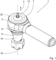
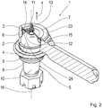
- FIG. 1 and 2 show different views of a ball joint 1 according to an embodiment, wherein Fig. 5 shows the ball joint 1 in the partially assembled state.
- the ball joint 1 has a passage opening 2 comprehensive joint housing 3 and a ball joint 4 comprehensive ball stud 5, which is articulated with its ball joint 4 in the joint housing 3 and extends out of this through the passage opening 2 out, so that the ball pin 5 with a pin portion 10 is disposed outside of the joint housing 3.
- the joint housing 3 further has a mounting opening 6, which is opposite to the passage opening 2 in a longitudinal direction x and is closed by a housing cover 7, which forms a housing bottom of the joint housing 3.
- the passage opening 2 is covered by a sealing bellows 8, through which the ball pin 5 extends through, wherein the sealing bellows 8 is fixed to the joint housing 3 and sealingly bears against both the joint housing 3 and on the ball pin 5.
- the ball pin 5 is slidably seated with its ball joint 4 in a bearing shell 9 arranged in the joint housing 3 and extends through a passage opening provided in the bearing shell 9.
- the joint ball 4 facing inner surface of the bearing shell 9 abuts against the joint ball 4 and forms a storage area 25 for the joint ball 4, the in Fig. 5 indicated by dashed lines.
- the ball joint 1 is associated with a central longitudinal axis 16 which extends in the longitudinal direction x.
- a lubricant chamber 12 is provided between the joint ball 4 and the housing cover 7, which is circumferentially bounded by the profile ring 11.
- the housing cover 7 is curved centrally outwards, so that the lubricant chamber 12 has the largest possible volume.
- a lubricating valve 13 opening into the lubricant chamber 12 is fastened, by means of which lubricant can be introduced into the lubricant chamber 12 from the outside.
- a gap 14 is provided, wherein the lubricant chamber 12 is connected by provided on the surface of the profile ring 11 lubricant grooves 15 with the gap 14, so through the lubricant valve 13 in the lubricant chamber 12 depressed lubricant from the lubricant chamber 12th can be introduced through the lubricant grooves 15 in the intermediate space 14.
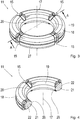
- Fig. 3 shows the profile ring 11, however, before assembly in its undeformed state, wherein Fig. 4 a section through the profile ring 11 along from Fig. 3 apparent sectional line AA and along the axis of rotation 17 of the profile ring 11, which coincides in the mounted state of the profile ring 11 in particular with the central longitudinal axis 16.
- each lubricant groove 15 is arranged distributed uniformly along the circumference of the profile ring 11 and formed identically.
- Each lubricant groove 15 runs around an outer side 18 of the profiled ring 11 around to an inner side 19 of the profiled ring 11.
- each lubricant groove 15 is designed to be circumferential except for a support region 20 which interrupts the course of the respective lubricant groove 15 and is provided on the inner side 19 of the profiled ring 11, wherein the support portion 20 is formed circumferentially with respect to the axis of rotation 17.
- the lubricant grooves 15 thus each have a C-shaped course.
- each lubricant groove 15 extends completely in a groove plane which comprises the axis of rotation 17.
- Fig. 3 includes one of these Nutebenen eg the rotation axis 17 and the section line AA. Furthermore, the profile ring 11 is mirror-symmetrical to a transverse plane to the axis of rotation 17 extending symmetry plane. In this case, the inner diameter of the profile ring 11 increases from the support region 20 with increasing distance to the support region 20 in the direction of the rotation axis 17, wherein the profile ring 11 has its smallest inner diameter at the support region 20. Furthermore, the support region 20 lies in the plane of symmetry. In Fig. 3 For example, the plane of symmetry on the outside 18 of the profile ring 11 has a groove 27 running around the axis of rotation 17, which lies in the plane of symmetry and can be used, for example, as an additional reservoir for lubricant.
- the profile ring 11 in the region of the lubricant grooves 15 in each case has a triangular cross-section 21, wherein one of the triangular sides 22 of this cross-section 21 is radially outward and extends in the direction of the axis of rotation 17. Further, one of the triangle sides 22 opposite corner 26 of the cross section 21 in the support portion 20, wherein the corner 26 is rounded.
- the profile ring 11 With his from the 3 and 4 apparent original shape in the joint housing 3 between the ball joint 4 and the housing cover 7 arranged, which made Fig. 5 is apparent. Subsequently, the housing cover 7 is pressed into the mounting opening 6 of the joint housing 3, so that the profile ring 11 is placed under compressive stress and up to his Fig. 2 deformed form deformed. Subsequently, the mounting opening 6 bounding edge 23 of the joint housing 3 is bent inwardly over the housing cover 7, which is thereby fixed to the joint housing 3.
- the profile ring 11 rests against the joint ball 4 with a contact region 24 that is larger than the support region 20, so that the support region 20 lies within the contact region 24.
- the lubrication grooves 15 thus extend in regions into the contact area 24.
Landscapes
- Engineering & Computer Science (AREA)
- General Engineering & Computer Science (AREA)
- Mechanical Engineering (AREA)
- Pivots And Pivotal Connections (AREA)
Claims (9)
- Articulation à rotule comprenant un boîtier d'articulation (3) comportant un fond de boîtier (7), une partie intérieure d'articulation (5) comportant une rotule d'articulation (4), laquelle partie intérieure d'articulation est, par sa rotule d'articulation (4), disposée dans le boîtier d'articulation (3) et s'étend hors de celui-ci, une bague profilée (11) élastique et disposée dans le boîtier d'articulation (3) entre la rotule d'articulation (4) et le fond de boîtier (7), laquelle bague profilée est constituée d'un élastomère ou de caoutchouc et laquelle comporte, sur son côté intérieur, une région d'appui (24) et est supportée sur la rotule d'articulation (4) par cette région d'appui, la bague profilée (11) étant supportée directement sur la rotule d'articulation (4) par la région d'appui (24), une chambre de lubrifiant (12) prévue dans le boîtier d'articulation (3) entre la rotule d'articulation (4) et le fond de boîtier (7), une région de palier (25) prévue dans le boîtier d'articulation (3) sur un côté de la bague profilée (11) opposé au fond de boîtier (7), région de palier sur laquelle la rotule d'articulation (4) est montée de manière articulée, un espace intermédiaire (14) prévu dans le boîtier d'articulation (3) entre la bague profilée (11) et la région de palier (25), et au moins une rainure pour lubrifiant (15) prévue dans la surface de la bague profilée (11) et reliant la chambre de lubrifiant (12) à l'espace intermédiaire (14), laquelle rainure pour lubrifiant s'étend le long d'un côté extérieur (18) de la bague profilée (11) tourné vers le boîtier d'articulation (3), caractérisée en ce que la rainure pour lubrifiant (15) s'étend à la fois dans la région de la chambre de lubrifiant (12) et dans la région de l'espace intermédiaire (14) jusqu'au côté intérieur (19) de la bague profilée (11) et/ou jusqu'à la région d'appui (24).
- Articulation à rotule selon la revendication 1, caractérisée en ce que la rainure pour lubrifiant (15) s'étend, dans son ensemble, dans un plan comportant l'axe de rotation (17) de la bague profilée (11).
- Articulation à rotule selon la revendication 1 ou 2, caractérisée en ce que la rainure pour lubrifiant (15) est formée de manière périphérique à l'exception d'une région de support (20) interrompant le tracé de la rainure pour lubrifiant (15) et prévue sur le côté intérieur (19) de la bague profilée (11), de telle sorte que la rainure pour lubrifiant (15) se termine à la fois dans la région de la chambre de lubrifiant (12) et dans la région de l'espace intermédiaire (14) au niveau de la région de support (20).
- Articulation à rotule selon la revendication 3, caractérisée en ce que la région d'appui comporte la région de support (20) et la bague profilée (11) est supportée sur la rotule d'articulation (4) au moins par la région de support (20).
- Articulation à rotule selon la revendication 4, caractérisée en ce que la région de support (20) est formée de manière périphérique par rapport à l'axe de rotation (17) de la bague profilée (11).
- Articulation à rotule selon la revendication 4 ou 5, caractérisée en ce que la région de support (20) se situe à l'intérieur de la région d'appui (24), la rainure pour lubrifiant (15) s'étendant à l'intérieur de la région d'appui (24) dans la région de la chambre de lubrifiant (12) et/ou dans la région de l'espace intermédiaire (14).
- Articulation à rotule selon l'une des revendications précédentes, caractérisée en ce qu'une soupape de lubrifiant (13) accessible depuis l'extérieur et débouchant dans la chambre de lubrifiant (12) est fixée au fond de boîtier (7), soupape à travers laquelle du lubrifiant peut être introduit à partir de l'extérieur dans la chambre de lubrifiant (12).
- Articulation à rotule selon l'une des revendications précédentes, caractérisée en ce qu'un coussinet de palier (9) comportant la région de palier (25) est inséré dans le boîtier d'articulation (3).
- Articulation à rotule selon l'une des revendications précédentes, caractérisée en ce que la bague profilée (11) est sous contrainte de compression, est déformée par rapport à sa forme d'origine et est pressée contre la rotule d'articulation (4) par sa région d'appui (24).
Applications Claiming Priority (2)
| Application Number | Priority Date | Filing Date | Title |
|---|---|---|---|
| DE102014225312.8A DE102014225312A1 (de) | 2014-12-09 | 2014-12-09 | Kugelgelenk |
| PCT/EP2015/076125 WO2016091511A1 (fr) | 2014-12-09 | 2015-11-10 | Joint sphérique |
Publications (2)
| Publication Number | Publication Date |
|---|---|
| EP3230607A1 EP3230607A1 (fr) | 2017-10-18 |
| EP3230607B1 true EP3230607B1 (fr) | 2019-09-25 |
Family
ID=54478036
Family Applications (1)
| Application Number | Title | Priority Date | Filing Date |
|---|---|---|---|
| EP15791302.1A Active EP3230607B1 (fr) | 2014-12-09 | 2015-11-10 | Joint sphérique |
Country Status (3)
| Country | Link |
|---|---|
| EP (1) | EP3230607B1 (fr) |
| DE (1) | DE102014225312A1 (fr) |
| WO (1) | WO2016091511A1 (fr) |
Cited By (1)
| Publication number | Priority date | Publication date | Assignee | Title |
|---|---|---|---|---|
| DE102023201943A1 (de) * | 2023-03-03 | 2024-09-05 | Zf Friedrichshafen Ag | Kugelgelenk für ein stangenförmiges Fahrwerkbauteil eines Nutzfahrzeugs |
Families Citing this family (2)
| Publication number | Priority date | Publication date | Assignee | Title |
|---|---|---|---|---|
| DE102017216488A1 (de) * | 2017-09-18 | 2019-03-21 | Zf Friedrichshafen Ag | Radialkugelgelenk für ein Lenkerbauteil eines Kraftfahrzeugs |
| US10895280B2 (en) * | 2018-03-06 | 2021-01-19 | Federal-Mogul Motorparts Llc | Socket assembly and method of making |
Family Cites Families (4)
| Publication number | Priority date | Publication date | Assignee | Title |
|---|---|---|---|---|
| US4087188A (en) * | 1976-03-03 | 1978-05-02 | Mceowen Victor R | Pivot joint housing |
| US4076344A (en) * | 1976-05-07 | 1978-02-28 | Gulf & Western Manufacturing Company | Bearing assembly for a ball and socket joint |
| US4003667A (en) * | 1976-05-21 | 1977-01-18 | Gulf & Western Manufacturing Company | Lubricatable ball joint assembly |
| DE102009002565A1 (de) | 2009-04-22 | 2010-11-11 | Zf Friedrichshafen Ag | Kugelgelenk, Verfahren zum Erstbefüllen eines derartigen Kugelgelenkes und Verfahren zum Austausch verbrauchten Schmiermittels in einem Kugelgelenk |
-
2014
- 2014-12-09 DE DE102014225312.8A patent/DE102014225312A1/de not_active Withdrawn
-
2015
- 2015-11-10 WO PCT/EP2015/076125 patent/WO2016091511A1/fr not_active Ceased
- 2015-11-10 EP EP15791302.1A patent/EP3230607B1/fr active Active
Non-Patent Citations (1)
| Title |
|---|
| None * |
Cited By (1)
| Publication number | Priority date | Publication date | Assignee | Title |
|---|---|---|---|---|
| DE102023201943A1 (de) * | 2023-03-03 | 2024-09-05 | Zf Friedrichshafen Ag | Kugelgelenk für ein stangenförmiges Fahrwerkbauteil eines Nutzfahrzeugs |
Also Published As
| Publication number | Publication date |
|---|---|
| WO2016091511A1 (fr) | 2016-06-16 |
| EP3230607A1 (fr) | 2017-10-18 |
| DE102014225312A1 (de) | 2016-06-09 |
Similar Documents
| Publication | Publication Date | Title |
|---|---|---|
| EP3311039B1 (fr) | Articulation à rotule | |
| DE19843063C1 (de) | Balgabdichtung | |
| EP3221610B1 (fr) | Palier élastomère pour véhicule | |
| DE10246354B4 (de) | Gleichlaufgelenkmanschette | |
| EP1611367B1 (fr) | Palier a douille en caoutchouc a amortissement hydraulique pour un montage vertical | |
| EP2090801A1 (fr) | Soufflet roulant d'un ressort pneumatique | |
| WO2016066599A1 (fr) | Couvercle de canal de refroidissement et piston pourvu d'un couvercle de canal de refroidissement | |
| DE102006021011A1 (de) | Buchsenlager mit axialseitig profiliertem Lagerkörper | |
| EP2251218A1 (fr) | Pièce de maintien articulée | |
| WO2016091511A1 (fr) | Joint sphérique | |
| EP1691104B1 (fr) | Support élastique | |
| EP2083191A1 (fr) | Palier | |
| DE102008049976A1 (de) | Federbeinlager sowie Federbein | |
| WO2018219586A1 (fr) | Coussinet de palier | |
| EP2935916B1 (fr) | Système articulé pour véhicule automobile | |
| DE102006034036B4 (de) | Radnaben-Drehgelenk-Anordnung mit Axialsicherung der Radnabe durch axiale Verspannung und radiale Verpressung | |
| DE19958502A1 (de) | Lager für einen schwenkbaren Hebel | |
| DE102014003915B4 (de) | Ölabstreifkolbenring | |
| DE202006000285U1 (de) | Elastomer-Metall-Gelenklager, insbesondere als Zentralgelenklager eines Dreieckslenkers zur Verbindung eines Achskörpers mit einem Fahrzeugaufbau | |
| DE102014220637A1 (de) | Massivkäfig für Zylinderrollenlager | |
| WO2016097097A1 (fr) | Frein à disque pour véhicule utilitaire | |
| DE202015009736U1 (de) | Dichtung und Ankersystem für sphärische Gelenklager | |
| DE102012218170A1 (de) | Vordichtung zum optionalen, nachträglichen Einbau | |
| WO2018149766A1 (fr) | Roue ferroviaire et corps élastique pour une telle roue ferroviaire | |
| DE102006007997B4 (de) | Elastisches Gelenklager |
Legal Events
| Date | Code | Title | Description |
|---|---|---|---|
| STAA | Information on the status of an ep patent application or granted ep patent |
Free format text: STATUS: THE INTERNATIONAL PUBLICATION HAS BEEN MADE |
|
| PUAI | Public reference made under article 153(3) epc to a published international application that has entered the european phase |
Free format text: ORIGINAL CODE: 0009012 |
|
| STAA | Information on the status of an ep patent application or granted ep patent |
Free format text: STATUS: REQUEST FOR EXAMINATION WAS MADE |
|
| 17P | Request for examination filed |
Effective date: 20170508 |
|
| AK | Designated contracting states |
Kind code of ref document: A1 Designated state(s): AL AT BE BG CH CY CZ DE DK EE ES FI FR GB GR HR HU IE IS IT LI LT LU LV MC MK MT NL NO PL PT RO RS SE SI SK SM TR |
|
| AX | Request for extension of the european patent |
Extension state: BA ME |
|
| DAV | Request for validation of the european patent (deleted) | ||
| DAX | Request for extension of the european patent (deleted) | ||
| GRAP | Despatch of communication of intention to grant a patent |
Free format text: ORIGINAL CODE: EPIDOSNIGR1 |
|
| STAA | Information on the status of an ep patent application or granted ep patent |
Free format text: STATUS: GRANT OF PATENT IS INTENDED |
|
| INTG | Intention to grant announced |
Effective date: 20190524 |
|
| GRAS | Grant fee paid |
Free format text: ORIGINAL CODE: EPIDOSNIGR3 |
|
| GRAA | (expected) grant |
Free format text: ORIGINAL CODE: 0009210 |
|
| STAA | Information on the status of an ep patent application or granted ep patent |
Free format text: STATUS: THE PATENT HAS BEEN GRANTED |
|
| AK | Designated contracting states |
Kind code of ref document: B1 Designated state(s): AL AT BE BG CH CY CZ DE DK EE ES FI FR GB GR HR HU IE IS IT LI LT LU LV MC MK MT NL NO PL PT RO RS SE SI SK SM TR |
|
| REG | Reference to a national code |
Ref country code: GB Ref legal event code: FG4D Free format text: NOT ENGLISH |
|
| REG | Reference to a national code |
Ref country code: CH Ref legal event code: EP |
|
| REG | Reference to a national code |
Ref country code: DE Ref legal event code: R096 Ref document number: 502015010477 Country of ref document: DE |
|
| REG | Reference to a national code |
Ref country code: AT Ref legal event code: REF Ref document number: 1184087 Country of ref document: AT Kind code of ref document: T Effective date: 20191015 |
|
| REG | Reference to a national code |
Ref country code: IE Ref legal event code: FG4D Free format text: LANGUAGE OF EP DOCUMENT: GERMAN |
|
| REG | Reference to a national code |
Ref country code: NL Ref legal event code: MP Effective date: 20190925 |
|
| PG25 | Lapsed in a contracting state [announced via postgrant information from national office to epo] |
Ref country code: HR Free format text: LAPSE BECAUSE OF FAILURE TO SUBMIT A TRANSLATION OF THE DESCRIPTION OR TO PAY THE FEE WITHIN THE PRESCRIBED TIME-LIMIT Effective date: 20190925 Ref country code: LT Free format text: LAPSE BECAUSE OF FAILURE TO SUBMIT A TRANSLATION OF THE DESCRIPTION OR TO PAY THE FEE WITHIN THE PRESCRIBED TIME-LIMIT Effective date: 20190925 Ref country code: BG Free format text: LAPSE BECAUSE OF FAILURE TO SUBMIT A TRANSLATION OF THE DESCRIPTION OR TO PAY THE FEE WITHIN THE PRESCRIBED TIME-LIMIT Effective date: 20191225 Ref country code: NO Free format text: LAPSE BECAUSE OF FAILURE TO SUBMIT A TRANSLATION OF THE DESCRIPTION OR TO PAY THE FEE WITHIN THE PRESCRIBED TIME-LIMIT Effective date: 20191225 Ref country code: SE Free format text: LAPSE BECAUSE OF FAILURE TO SUBMIT A TRANSLATION OF THE DESCRIPTION OR TO PAY THE FEE WITHIN THE PRESCRIBED TIME-LIMIT Effective date: 20190925 Ref country code: FI Free format text: LAPSE BECAUSE OF FAILURE TO SUBMIT A TRANSLATION OF THE DESCRIPTION OR TO PAY THE FEE WITHIN THE PRESCRIBED TIME-LIMIT Effective date: 20190925 |
|
| REG | Reference to a national code |
Ref country code: LT Ref legal event code: MG4D |
|
| PG25 | Lapsed in a contracting state [announced via postgrant information from national office to epo] |
Ref country code: RS Free format text: LAPSE BECAUSE OF FAILURE TO SUBMIT A TRANSLATION OF THE DESCRIPTION OR TO PAY THE FEE WITHIN THE PRESCRIBED TIME-LIMIT Effective date: 20190925 Ref country code: GR Free format text: LAPSE BECAUSE OF FAILURE TO SUBMIT A TRANSLATION OF THE DESCRIPTION OR TO PAY THE FEE WITHIN THE PRESCRIBED TIME-LIMIT Effective date: 20191226 Ref country code: LV Free format text: LAPSE BECAUSE OF FAILURE TO SUBMIT A TRANSLATION OF THE DESCRIPTION OR TO PAY THE FEE WITHIN THE PRESCRIBED TIME-LIMIT Effective date: 20190925 |
|
| PG25 | Lapsed in a contracting state [announced via postgrant information from national office to epo] |
Ref country code: PT Free format text: LAPSE BECAUSE OF FAILURE TO SUBMIT A TRANSLATION OF THE DESCRIPTION OR TO PAY THE FEE WITHIN THE PRESCRIBED TIME-LIMIT Effective date: 20200127 Ref country code: AL Free format text: LAPSE BECAUSE OF FAILURE TO SUBMIT A TRANSLATION OF THE DESCRIPTION OR TO PAY THE FEE WITHIN THE PRESCRIBED TIME-LIMIT Effective date: 20190925 Ref country code: RO Free format text: LAPSE BECAUSE OF FAILURE TO SUBMIT A TRANSLATION OF THE DESCRIPTION OR TO PAY THE FEE WITHIN THE PRESCRIBED TIME-LIMIT Effective date: 20190925 Ref country code: ES Free format text: LAPSE BECAUSE OF FAILURE TO SUBMIT A TRANSLATION OF THE DESCRIPTION OR TO PAY THE FEE WITHIN THE PRESCRIBED TIME-LIMIT Effective date: 20190925 Ref country code: PL Free format text: LAPSE BECAUSE OF FAILURE TO SUBMIT A TRANSLATION OF THE DESCRIPTION OR TO PAY THE FEE WITHIN THE PRESCRIBED TIME-LIMIT Effective date: 20190925 Ref country code: EE Free format text: LAPSE BECAUSE OF FAILURE TO SUBMIT A TRANSLATION OF THE DESCRIPTION OR TO PAY THE FEE WITHIN THE PRESCRIBED TIME-LIMIT Effective date: 20190925 Ref country code: NL Free format text: LAPSE BECAUSE OF FAILURE TO SUBMIT A TRANSLATION OF THE DESCRIPTION OR TO PAY THE FEE WITHIN THE PRESCRIBED TIME-LIMIT Effective date: 20190925 Ref country code: IT Free format text: LAPSE BECAUSE OF FAILURE TO SUBMIT A TRANSLATION OF THE DESCRIPTION OR TO PAY THE FEE WITHIN THE PRESCRIBED TIME-LIMIT Effective date: 20190925 |
|
| PG25 | Lapsed in a contracting state [announced via postgrant information from national office to epo] |
Ref country code: SK Free format text: LAPSE BECAUSE OF FAILURE TO SUBMIT A TRANSLATION OF THE DESCRIPTION OR TO PAY THE FEE WITHIN THE PRESCRIBED TIME-LIMIT Effective date: 20190925 Ref country code: IS Free format text: LAPSE BECAUSE OF FAILURE TO SUBMIT A TRANSLATION OF THE DESCRIPTION OR TO PAY THE FEE WITHIN THE PRESCRIBED TIME-LIMIT Effective date: 20200224 Ref country code: CZ Free format text: LAPSE BECAUSE OF FAILURE TO SUBMIT A TRANSLATION OF THE DESCRIPTION OR TO PAY THE FEE WITHIN THE PRESCRIBED TIME-LIMIT Effective date: 20190925 Ref country code: SM Free format text: LAPSE BECAUSE OF FAILURE TO SUBMIT A TRANSLATION OF THE DESCRIPTION OR TO PAY THE FEE WITHIN THE PRESCRIBED TIME-LIMIT Effective date: 20190925 |
|
| REG | Reference to a national code |
Ref country code: DE Ref legal event code: R097 Ref document number: 502015010477 Country of ref document: DE |
|
| REG | Reference to a national code |
Ref country code: CH Ref legal event code: PL |
|
| PG2D | Information on lapse in contracting state deleted |
Ref country code: IS |
|
| PG25 | Lapsed in a contracting state [announced via postgrant information from national office to epo] |
Ref country code: LU Free format text: LAPSE BECAUSE OF NON-PAYMENT OF DUE FEES Effective date: 20191110 Ref country code: MC Free format text: LAPSE BECAUSE OF FAILURE TO SUBMIT A TRANSLATION OF THE DESCRIPTION OR TO PAY THE FEE WITHIN THE PRESCRIBED TIME-LIMIT Effective date: 20190925 Ref country code: LI Free format text: LAPSE BECAUSE OF NON-PAYMENT OF DUE FEES Effective date: 20191130 Ref country code: CH Free format text: LAPSE BECAUSE OF NON-PAYMENT OF DUE FEES Effective date: 20191130 Ref country code: DK Free format text: LAPSE BECAUSE OF FAILURE TO SUBMIT A TRANSLATION OF THE DESCRIPTION OR TO PAY THE FEE WITHIN THE PRESCRIBED TIME-LIMIT Effective date: 20190925 Ref country code: IS Free format text: LAPSE BECAUSE OF FAILURE TO SUBMIT A TRANSLATION OF THE DESCRIPTION OR TO PAY THE FEE WITHIN THE PRESCRIBED TIME-LIMIT Effective date: 20200126 |
|
| PLBE | No opposition filed within time limit |
Free format text: ORIGINAL CODE: 0009261 |
|
| STAA | Information on the status of an ep patent application or granted ep patent |
Free format text: STATUS: NO OPPOSITION FILED WITHIN TIME LIMIT |
|
| REG | Reference to a national code |
Ref country code: BE Ref legal event code: MM Effective date: 20191130 |
|
| 26N | No opposition filed |
Effective date: 20200626 |
|
| GBPC | Gb: european patent ceased through non-payment of renewal fee |
Effective date: 20191225 |
|
| PG25 | Lapsed in a contracting state [announced via postgrant information from national office to epo] |
Ref country code: IE Free format text: LAPSE BECAUSE OF NON-PAYMENT OF DUE FEES Effective date: 20191110 Ref country code: FR Free format text: LAPSE BECAUSE OF NON-PAYMENT OF DUE FEES Effective date: 20191125 Ref country code: GB Free format text: LAPSE BECAUSE OF NON-PAYMENT OF DUE FEES Effective date: 20191225 |
|
| PG25 | Lapsed in a contracting state [announced via postgrant information from national office to epo] |
Ref country code: SI Free format text: LAPSE BECAUSE OF FAILURE TO SUBMIT A TRANSLATION OF THE DESCRIPTION OR TO PAY THE FEE WITHIN THE PRESCRIBED TIME-LIMIT Effective date: 20190925 Ref country code: BE Free format text: LAPSE BECAUSE OF NON-PAYMENT OF DUE FEES Effective date: 20191130 |
|
| PG25 | Lapsed in a contracting state [announced via postgrant information from national office to epo] |
Ref country code: CY Free format text: LAPSE BECAUSE OF FAILURE TO SUBMIT A TRANSLATION OF THE DESCRIPTION OR TO PAY THE FEE WITHIN THE PRESCRIBED TIME-LIMIT Effective date: 20190925 |
|
| PG25 | Lapsed in a contracting state [announced via postgrant information from national office to epo] |
Ref country code: MT Free format text: LAPSE BECAUSE OF FAILURE TO SUBMIT A TRANSLATION OF THE DESCRIPTION OR TO PAY THE FEE WITHIN THE PRESCRIBED TIME-LIMIT Effective date: 20190925 Ref country code: HU Free format text: LAPSE BECAUSE OF FAILURE TO SUBMIT A TRANSLATION OF THE DESCRIPTION OR TO PAY THE FEE WITHIN THE PRESCRIBED TIME-LIMIT; INVALID AB INITIO Effective date: 20151110 |
|
| REG | Reference to a national code |
Ref country code: AT Ref legal event code: MM01 Ref document number: 1184087 Country of ref document: AT Kind code of ref document: T Effective date: 20201110 |
|
| PG25 | Lapsed in a contracting state [announced via postgrant information from national office to epo] |
Ref country code: AT Free format text: LAPSE BECAUSE OF NON-PAYMENT OF DUE FEES Effective date: 20201110 |
|
| PG25 | Lapsed in a contracting state [announced via postgrant information from national office to epo] |
Ref country code: TR Free format text: LAPSE BECAUSE OF FAILURE TO SUBMIT A TRANSLATION OF THE DESCRIPTION OR TO PAY THE FEE WITHIN THE PRESCRIBED TIME-LIMIT Effective date: 20190925 |
|
| PG25 | Lapsed in a contracting state [announced via postgrant information from national office to epo] |
Ref country code: MK Free format text: LAPSE BECAUSE OF FAILURE TO SUBMIT A TRANSLATION OF THE DESCRIPTION OR TO PAY THE FEE WITHIN THE PRESCRIBED TIME-LIMIT Effective date: 20190925 |
|
| P01 | Opt-out of the competence of the unified patent court (upc) registered |
Effective date: 20230528 |
|
| PGFP | Annual fee paid to national office [announced via postgrant information from national office to epo] |
Ref country code: DE Payment date: 20250916 Year of fee payment: 11 |