EP3230643B1 - Élément de liaison pour un ou plusieurs tubes souples ayant agencement de verrouillage amélioré - Google Patents
Élément de liaison pour un ou plusieurs tubes souples ayant agencement de verrouillage amélioré Download PDFInfo
- Publication number
- EP3230643B1 EP3230643B1 EP14815623.5A EP14815623A EP3230643B1 EP 3230643 B1 EP3230643 B1 EP 3230643B1 EP 14815623 A EP14815623 A EP 14815623A EP 3230643 B1 EP3230643 B1 EP 3230643B1
- Authority
- EP
- European Patent Office
- Prior art keywords
- ring sleeve
- mandrel
- connecting element
- main body
- sealing edge
- Prior art date
- Legal status (The legal status is an assumption and is not a legal conclusion. Google has not performed a legal analysis and makes no representation as to the accuracy of the status listed.)
- Active
Links
Images

Classifications
-
- F—MECHANICAL ENGINEERING; LIGHTING; HEATING; WEAPONS; BLASTING
- F16—ENGINEERING ELEMENTS AND UNITS; GENERAL MEASURES FOR PRODUCING AND MAINTAINING EFFECTIVE FUNCTIONING OF MACHINES OR INSTALLATIONS; THERMAL INSULATION IN GENERAL
- F16L—PIPES; JOINTS OR FITTINGS FOR PIPES; SUPPORTS FOR PIPES, CABLES OR PROTECTIVE TUBING; MEANS FOR THERMAL INSULATION IN GENERAL
- F16L33/00—Arrangements for connecting hoses to rigid members; Rigid hose-connectors, i.e. single members engaging both hoses
- F16L33/24—Arrangements for connecting hoses to rigid members; Rigid hose-connectors, i.e. single members engaging both hoses with parts screwed directly on or into the hose
-
- F—MECHANICAL ENGINEERING; LIGHTING; HEATING; WEAPONS; BLASTING
- F16—ENGINEERING ELEMENTS AND UNITS; GENERAL MEASURES FOR PRODUCING AND MAINTAINING EFFECTIVE FUNCTIONING OF MACHINES OR INSTALLATIONS; THERMAL INSULATION IN GENERAL
- F16L—PIPES; JOINTS OR FITTINGS FOR PIPES; SUPPORTS FOR PIPES, CABLES OR PROTECTIVE TUBING; MEANS FOR THERMAL INSULATION IN GENERAL
- F16L37/00—Couplings of the quick-acting type
- F16L37/08—Couplings of the quick-acting type in which the connection between abutting or axially overlapping ends is maintained by locking members
- F16L37/10—Couplings of the quick-acting type in which the connection between abutting or axially overlapping ends is maintained by locking members using a rotary external sleeve or ring on one part
Definitions
- the present invention relates to a connecting element for at least one flexible tube.
- the connecting element and the one or more flexible tubes are provided for an irrigation system.
- the irrigation system is provided for an automatic watering of plants.
- the irrigation system is suitable for domestic applications.
- Such connecting elements are known from US 3,788,676 A1 .
- a connecting element for at least one flexible tube of an irrigation system should allow that one or more flexible tubes can be connected and disconnected in an easy and speedy way. Further, the connecting element should be easily operated without any technical manual. Moreover, the connecting element should guarantee a seal connection. Additionally, the connecting element should be weather-resistant. Preferably, the connecting element should comprise an integrative design. In particular, the connecting element should have a low number of components. At last, the connecting element should be realized by low costs. It is an object of the present invention to provide a connecting element for at least one flexible tube, wherein the connecting element allows an easy handling by the user.
- the object of the present invention is achieved by the connecting element according to claim 1 and by the method of production according to claim 14.
- the present invention provides a connecting element for connecting at least one flexible tube, wherein
- the core of the present invention are the structures of the ring sleeve and the main body, in particular the inner structure of the ring sleeve and the outer structure of the main body, which allow the certain movability of the ring sleeve relative to the mandrel and guarantee the, preferably permanent, connection of the ring sleeve to the main body.
- All components of the connecting element i.e. the main body and the one or more ring sleeves, are always connected together, so that said components preferably can not be lost.
- the user has to hold only those two subjects, but not any further parts.
- the main body with the central portion and the one or more mandrels is formed as a single-piece part.
- the main body and/or the ring sleeve includes at least one notch extending on the circumference of the main body and/or the ring sleeve, respectively, wherein at least one cam of the ring sleeve and/or main body, respectively, is guided or guidable within said notch during the ring sleeve is rotated relative to the mandrel.
- the cam or cams and the notch allow a stable, but rotatable connection between the main body and the ring sleeve.
- the main body and/or the ring sleeve may include at least one stopper in order to limit the rotation angle of the ring sleeve relative to the mandrel, wherein preferably the stopper is arranged within the notch, and wherein preferably the stopper interacts with the cam of the ring sleeve.
- the stopper guarantees that the ring sleeve is rotatable within the predetermined angle only.
- At least one bump may be formed in the bottom of the notch, wherein said bump signalise appreciably to the user, when the ring sleeve has reached the opened state and/or the closed state, and wherein preferably the at least one bump is arranged between two stoppers.
- the main body and the at least one ring sleeve are interconnected by bonds, wherein said bonds are provided as predetermined breaking points, so that the connecting element forms a single-piece part after its production until a first use, and wherein preferably the connecting element is in the opened state when the main body and the at least one ring sleeve are interconnected by the bonds.
- the cross-section of at least one mandrel is non-circular, in particular elliptic or oval or polygonal, wherein the ring sleeve includes at least two cutting edges engaged or engageable in the closed state with the flexible tube encasing said mandrel, wherein the cutting edges are arranged at peripheral opposite sides in the interior of the ring sleeve and extend parallel to the rotating direction of said ring sleeve, wherein preferably the predetermined rotation angle of the ring sleeve relative to the mandrel is about 90 degrees.
- the non-circular, in particular elliptic or oval, cross-section of the mandrel allows that the peripheral distances between the ring sleeve and the mandrel are changed during the predetermined rotation between the opened state and closed state.
- the opposite cutting edges allow the form fit between the flexible tube and the mandrel in the closed state and an easy removing of the flexible tube from the mandrel in the opened state. Since the predetermined rotation angle of the ring sleeve relative to the mandrel is preferably about 90 degrees, the cutting edges are arrangeable beside the long sides of the non-circular cross-section in the opened state and at the small sides of the non-circular cross-section in the closed state.
- the mandrel may include at least one sealing edge enclosing circumferentially said mandrel, wherein preferably at least one sealing edge is arranged close to the cutting edges of the ring sleeve.
- the sealing edge supports the form fit between the flexible tube and the mandrel.
- the sealing edge comprises a triangular cross-section with a first edge angle and a second edge angle, wherein the first edge angle is closer to the open end of the mandrel than the second edge angle, and wherein the first edge angle is smaller than the second edge angle.
- the small first edge angle allows an easy movement of the flexible tube on the mandrel.
- the mandrel may include at least two sealing edges enclosing circumferentially said mandrel, wherein a first sealing edge is closer to the open end of the mandrel than a second sealing edge, and wherein the diameter of the first sealing edge is smaller than the diameter of the second sealing edge.
- the mandrel may include more than two sealing edges, wherein the diameter of the sealing edges increases with the distance from the open end of the mandrel.
- the mandrel may be connected to flexible tubes with different diameters.
- a front edge of at least one mandrel may be inclined, wherein said front edge is arranged at an outer end of the mandrel.
- the inclined front edge of the mandrel allows an easy movement of the flexible tube onto the mandrel by the user. During the movement of the flexible tube onto the mandrel the flexible tube is increasingly centred and the inner wall of the flexible tube is slightly expanded.
- the inclined front edge of the mandrel facilitates the movement of the flexible tube on the mandrel by the user.
- an outer end of at least one ring sleeve includes a bevel at its inner side, so that the outer end of the ring sleeve is funnel shaped, and/or the inclined front edge of at least one mandrel is at least partially enclosed by an outer bevel.
- the funnel shaped ring sleeve facilitates the insertion of the flexible tube into said ring sleeve.
- the outer bevel additionally facilitates the movement of the flexible tube on the mandrel by the user.
- At least one sealing edge may be inclined.
- the inclined sealing edge facilitates the movement of the flexible tube onto the mandrel.
- the ring sleeve includes at least one opening in its peripheral wall, so that a part of the mandrel is visible, wherein preferably a section of the at least one sealing edge is visible.
- the user can control the position of the flexible tube moved onto the mandrel.
- At least one ring sleeve may include at least two gripping elements at its peripheral side, wherein preferably the gripping elements are arranged at opposite sides of the ring sleeve.
- the main body may include a recess enclosing at least partially the central portion of said main body, wherein preferably the recess is formed by a plurality of ribs including rounded edges.
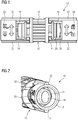
- Figure 1 illustrates schematic side view of a connecting element 10 according to a preferred embodiment of the present invention.
- the connecting element 10 is provided for connecting two flexible tubes 30 with each other.
- the connecting element 10 comprises a main body 12 and two ring sleeves 14.
- the main body 12 is formed as a single-piece part and includes a central portion 16 and two mandrels 18.
- the mandrels 18 are arranged at two opposing sides of the central portion 16.
- the mandrels 18 projects from the central portion 16 into two opposite directions.
- the central portion 16 and the mandrels 18 are hollow, wherein a duct is formed inside the main body 12.
- the duct extends between the mandrels 18 via the central portion 16. In this example, the duct is substantially linear.
- Each mandrel 18 forms a pipe socket provided for being encased by one of the flexible tubes.
- the mandrel 18 is enclosed by one or more sealing edges 26 and 28.
- the main body 12 with the sealing edges 26 and 28 form a single-piece part.
- Each ring sleeve 14 encloses one of the mandrels 18.
- the ring sleeve 14 is substantially formed as a hollow cylinder.
- the ring sleeves 14 are rotatable on the mandrel 18 around their symmetry axes between an opened state and a closed state.
- the mandrel 18 includes on its outer side at least one circumferential notch, in which cams at the inner side of the ring sleeve 14 are guided.
- the ring sleeve 14 may include at its inner side one or more circumferential notches, in which protrusions on the outer side of the mandrel 18 are guided.
- the angle between said opened state and closed state is about 90 degrees.
- the ring sleeve 14 seals the flexible tube encasing the mandrel 18.
- the flexible tube is strongly connected to the connecting element 10.
- the flexible tube can be easily pulled down from the mandrel 18.
- the connecting element 10 comprises the main body 12 with two mandrels 18 and two corresponding ring sleeves 14, so that the connecting element 10 is provided for connecting two flexible tubes.
- the connecting element 10 may comprise a main body 12 with one or more mandrels 18 and the corresponding number of ring sleeves 14, so that the connecting element 10 is provided for connecting the corresponding number of one or more flexible tubes.
- each ring sleeve 14 includes a figurative brief instruction 20 indicating the rotating directions in order to obtain the opened and closed state, respectively.
- each ring sleeve 14 includes at least one grip element 22 at its outer circumferential side.
- the ring sleeve 14 includes two grip elements 22 arranged at opposite sides. The grip elements 22 facilitate the rotation of the ring sleeve 14 by the user.
- Figure 2 illustrates a part of a schematic perspective view of the connecting element 10 according to the preferred embodiment of the present invention. In Figure 2 only one of the ring sleeves 14 is shown.
- the connecting element 10 comprises the main body 12 and the two ring sleeves 14, wherein only one of the ring sleeves 14 is shown in Figure 2 .
- the ring sleeve 14 encloses the mandrel 18.
- the ring sleeve 14 includes the figurative brief instruction 20 indicating the rotating directions for the opened and closed state, respectively. Further, the ring sleeve 14 includes the two grip elements 22 arranged at opposite sides.
- the mandrel 18 includes a non-circular, in particular elliptic or oval or polygonal, cross-section.
- the non-circular cross-section of the mandrel 18 allows a form fit between the flexible tube and mandrel 18 in combination with a suitable inner structure of the ring sleeve 14 and a suitable outer structure of the mandrel 18.
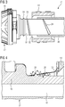
- Figure 3 illustrates a schematic partial sectional side view of the connecting element 10 according to the preferred embodiment of the present invention.
- a side view of the main body 12 and a sectional side view of one of the ring sleeve 14 and flexible tube 30 are illustrated in Figure 3 .
- the connecting element 10 comprises the main body 12 and the two ring sleeves 14, wherein Figure 3 shows only one of the ring sleeves 14.
- the ring sleeve 14 encloses the mandrel 18.
- the flexible tube 30 partially encases the mandrel 18.
- the ring sleeve 14 partially encloses the flexible tube 30.
- a front edge 24 of the mandrel 18 is inclined.
- the inclined front edge 24 of the mandrel 18 allows an easy movement of the flexible tube 30 onto the mandrel 18 by the user.
- the flexible tube 30 is increasingly centred and the inner wall of the flexible tube 30 is slightly expanded.
- the inclined front edge 24 of the mandrel 18 facilitates the movement of the flexible tube 30 on the mandrel 18 by the user.
- the mandrel 18 includes a first sealing edge 26 and a second sealing edge 28.
- the first sealing edge 26 and the second sealing edge 28 enclose the mandrel 18 along its peripheral direction.
- the first sealing edge 26 is closer to the front edge 24 as the second sealing edge 28.
- the flexible tube 30 being moved onto the mandrel 18 passes at first the first sealing edge 26 and then the second sealing edge 28.
- the mandrel 18, the first sealing edge 26 and the second sealing edge 28 form a single-piece part.
- the first sealing edge 26 and the second sealing edge 28 have a triangular cross-section in each case.
- the first sealing edge 26 is inclined, while the second sealing edge 28 is straight.
- the inclined first sealing edge 26 allows also an easy movement of the flexible tube 30 onto the mandrel 18 by the user.
- the front edge 24 as well as the first sealing edge 26 of the mandrel 18 is inclined.
- the front edge 24 of the mandrel 18 may be inclined, while the first sealing edge 26 of the mandrel 18 may be straight.
- the first sealing edge 26 of the mandrel 18 may be inclined, while the front edge 24 of the mandrel 18 may be straight.
- the inclined front edge 24 and/or inclined sealing edge 26 are suitable for the mandrel 18 with the non-circular, in particular elliptic or oval or polygonal, cross-section, but also for a mandrel 18 with another cross-section, for example a circular cross-section.
- the ring sleeve 14 includes two cutting edges 32 arranged at opposite sides in the interior of said ring sleeve 14. The cutting edges 32 are aligned parallel to the direction of rotation of the ring sleeve 14.
- Figure 4 illustrates a part of a schematic sectional side view of the connecting element 10 according to the preferred embodiment of the present invention.
- the connecting element 10 comprises the main body 12 and the two ring sleeves 14. In Figure 4 only one of the ring sleeves 14 is partially shown.
- the mandrel 18 includes the first sealing edge 26 and the second sealing edge 28.
- the first sealing edge 26 and the second sealing edge 28 enclose the mandrel 18 along its peripheral direction.
- the first sealing edge 26 is closer to the front edge 24 as the second sealing edge 28.
- the mandrel 18, the first sealing edge 26 and the second sealing edge 28 form a single-piece part.
- the first sealing edge 26 and the second sealing edge 28 have a triangular cross-section in each case.
- the triangular cross-section of the first sealing edge 26 is smaller than the triangular cross-section of the second sealing edge 28.
- the diameter of the first sealing edge 26 is smaller than the diameter of the second sealing edge 28.
- the first sealing edge 26 is provided for sealing flexible tubes 30 having a relative small diameter.
- the second sealing edge 28 is provided for sealing flexible tubes 30 having a relative big diameter.
- a first edge angle ⁇ of each sealing edge 26 and 28 is facing the front edge 24 of the mandrel 18.
- a second edge angle ⁇ of each sealing edge 26 and 28 is averted said front edge 24 of the mandrel 18.
- the first edge angle ⁇ is smaller than the second edge angle ⁇ . This allows an easy movement of the flexible tube 30 on the mandrel 18.
- the first edge angle ⁇ and the second edge angle ⁇ are both smaller than 90 degrees. This also contributes to the easy movement of the flexible tube 30 on the mandrel 18.
- first sealing edge 26 and the second sealing edge 28 are straight.
- at least one of the sealing edges 26 and 28, preferably the first sealing edge 26, is inclined.
- the front edge 24 of the mandrel 18 may be inclined or straight.
- the first sealing edge 26 and the second sealing edge 28 in Figure 4 are suitable for the mandrel 18 with the non-circular, in particular elliptic or oval or polygonal, cross-section, but also for a mandrel 18 with another cross-section, for example a circular cross-section.
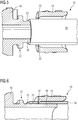
- Figure 5 illustrates a schematic partial sectional side view of the connecting element 10 and the flexible tube 30 according to the preferred embodiment of the present invention, wherein the connecting element 10 is in the opened state.
- the flexible tube 30 has been moved above the first sealing edge 26.
- the diameter of the flexible tube 30 is relative small.
- the flexible tube 30 is sealed by the first sealing edge 26, while the second sealing edge 28 remains uncovered.
- the cutting edges 32 of the ring sleeve 14 are not engaged with the flexible tube 30, since said cutting edges 32 are arranged beside the both long sides of the non-circular cross-section of the flexible tube 30.
- the non-circular cross-section of the flexible tube 30 results from the non-circular cross-section of the mandrel 18.
- Figure 6 illustrates a schematic partial sectional side view of the connecting element 10 and the flexible tube 30 according to the preferred embodiment of the present invention, wherein the connecting element 10 is in the closed state.
- the ring sleeve 14 shown in Figure 6 has been rotated about 90 degrees.
- the cutting edges 32 of the ring sleeve 14 are arranged at the both small sides of the non-circular elliptic or oval, cross-section of the flexible tube 30 and are engaged with said flexible tube 30, wherein the cutting edges 32 are arranged close to the first sealing edge 26.
- the form fit between the mandrel 18 and the flexible tube 30 is obtained.
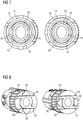
- Figure 7 illustrates two schematic sectional front views of the connecting element 10 and the flexible tube 30 according to the preferred embodiment of the present invention in the opened state and in the closed state, respectively.
- the connecting element 10 On the left hand side the connecting element 10 is in the opened state, while the right hand side shows the connecting element 10 in the closed state.
- the ring sleeve 14 encloses the flexible tube 30.
- the flexible tube 30 encases the mandrel 18 of the main body 12.
- the mandrel 18 has the non-circular, in particular elliptic or oval or polygonal, cross-section.
- the flexible tube 30 encasing said mandrel 18 has the non-circular, in particular elliptic or oval or polygonal, cross-section.
- the ring sleeve 14 includes the two cutting edges 32 arranged at opposite sides in the interior of said ring sleeve 14.
- the cutting edges 32 are aligned parallel to the direction of rotation of the ring sleeve 14.
- the cutting edges 32 are arranged beside the long sides of the non-circular cross-section of the flexible tube 30.
- the ring sleeve 14 has been rotated about 90 degrees, wherein the cutting edges 32 are arranged at the small sides of the non-circular cross-section of the flexible tube 30.
- the cutting edges 32 are engaged with the flexible tube 30.
- the form fit between the mandrel 18 and the flexible tube 30 is obtained.
- Figure 8 illustrates two schematic sectional perspective views of the connecting element 10 according to the preferred embodiment of the present invention in the opened state and in the closed state, respectively.
- the connecting element 10 On the left hand side the connecting element 10 is in the opened state.
- the connecting element 10 in the closed state On the right hand side the connecting element 10 in the closed state is shown.
- the main body 12 includes two stoppers 34 for each ring sleeve 14.
- the stoppers are arranged around the non-circular mandrel 18.
- the stoppers 34 effect that the ring sleeves 14 can only be rotated between the opened state and the closed state.
- the stoppers 34 prevent over rotation of the ring sleeve 34, wherein the cutting edge 32 would run away from a biting position in the flexible tube 30.
- the stoppers 34 can acknowledge a user that the desired rotation has been accomplished for proper gripping of the flexible tube 30 by the biting of the cutting edges 32 into the flexible tube 30.
- the ring sleeve 14 includes two cams 36. During the rotation of the ring sleeve 14 said cams 36 are moved in a notch of the main body 12. Two bumps 38 are formed in the bottom of said notch. Each bump 38 is arranged between two stoppers 34. The bumps 38 signalise appreciably to the user, when the ring sleeve 14 has reached the opened or closed state.
- the stoppers 34 and the bumps 38 are positioned in outer portions and may be formed by a lateral opening of the injection moulding.
- the main body 12 with the stoppers 34 and the bumps 38 forms a single-piece part.
- Figure 9 illustrates a part of a schematic side view and a corresponding part of a schematic top view of the connecting element 10 according to the preferred embodiment of the present invention.
- the schematic side view of the connecting element 10 is on the left hand side, while the schematic top view of said connecting element 10 is on the right hand side.
- the connecting element 10 includes at least one bond 40 between the main body 12 and each ring sleeve 14.
- the bonds 40 are provided as predetermined breaking points.
- the bonds 40 break, so that the main body 12 and the at least two ring sleeves 14 are separate parts.
- the bonds 40 are very thin.
- the main body 12 and the ring sleeves 14 remain moveably connected, after the bonds have been broken.
- the cams 36 of the ring sleeve 14 and the notch of the main body 12 remain locked, so that the ring sleeve 14 can be rotated at the main body 12 between the opened and closed state, but not removed from said main body 12.
- the connecting element 10 is an injection moulded.
- the main body 12, the at least two ring sleeves 14 and the bonds 40 between them form a single-piece injection moulded.
- the arrangement of the connecting element 10 as single-piece part facilitates the production and distribution of said connecting element 10.
- the freshly produced connecting element 10 as single-piece part is in the opened state.
- the freshly produced connecting element 10 is in a "ready-to-use"-state.
- the user can directly insert the flexible tube 30 between the mandrel 18 and the ring sleeve 14.
- the at least one bond 40 breaks.
- the schematic side top view of the connecting element 10 on the right hand side clarifies that the bonds are relative small and thin.
- Figure 10 illustrates a part of a schematic side view of the connecting element 10 and the flexible tube 30 according to the preferred embodiment of the present invention.
- the ring sleeve 14 includes an opening 42.
- the opening 42 is represented by a shaded area in Figure 10 .
- the opening 42 is positioned that the first sealing edge 26 and the second sealing edge 28 are partially visible in the absence of the flexible tube 30.
- the opening 42 forms a viewing window, so that the user can monitor the positioning of the flexible tube 30 on the mandrel 18.
- the figurative brief instruction 20 is arranged besides the opening 42.
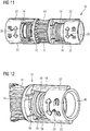
- Figure 11 illustrates a schematic perspective view of the connecting element 10 according to the preferred embodiment of the present invention.
- the main body 12 of the connecting element 10 includes a recess 44.
- Said recess 44 encloses peripherally the central portion 16 of the main body 12.
- the recess 44 allows that the user can certainly hold tight the main body 12 of the connecting element 10, when the flexible tube 30 is moved onto the mandrel 18 and the ring sleeve 14 is rotated relative to said main body 12.
- the recess 44 is formed by a plurality of ribs. Said ribs include rounded edges.
- the main body 12 can certainly hold tight by the user without any sharp edges.
- the grip elements 22 of the ring sleeves 14 allow that the user can certainly hold tight said ring sleeves 14.
- Figure 12 illustrates a part of a schematic perspective view of the connecting element 10 according to the preferred embodiment of the present invention.
- the ring sleeve 14 includes a bevel 46 at the inner edge of its outer end.
- the bevel 46 causes that the outer end is funnel shaped.
- the funnel shaped outer end of the ring sleeve 14 facilitates the insertion of the flexible tube 30 into the ring sleeve 14.
- the inclined front edge 24 of the mandrel 18 supports that the flexible tube 30 encases the mandrel 18.
Landscapes
- Engineering & Computer Science (AREA)
- General Engineering & Computer Science (AREA)
- Mechanical Engineering (AREA)
- Quick-Acting Or Multi-Walled Pipe Joints (AREA)
Claims (15)
- Élément de raccordement (10) servant à des fins de raccordement d'au moins un tube flexible (30), dans lequel- l'élément de raccordement (10) comporte un corps principal (12) et au moins un manchon annulaire (14),- le corps principal (12) comprend une partie centrale (16) et au moins un mandrin (18) s'étendant à l'opposé de ladite partie centrale (16),- un conduit s'étend entre les mandrins (18) par le biais de la partie centrale (16) ou à l'intérieur du mandrin (18) jusqu'à la partie centrale (16), respectivement,- au moins un mandrin (18) est renfermé par un manchon annulaire (14),- le manchon annulaire (14) est raccordé de manière permanente, mais mobile, au corps principal (12),- le manchon annulaire (14) est rotatif par rapport au mandrin (18), en particulier autour d'un angle de rotation prédéterminé, entre un état ouvert et un état fermé,- le mandrin (18) est en mesure d'être inséré dans le tube flexible (30), alors que ledit tube flexible (30) est en mesure d'être renfermé, respectivement, par le manchon annulaire correspondant (14),- une complémentarité de forme entre le tube flexible (30) et le mandrin (18) est en mesure d'être obtenue dans l'état fermé, et- le corps principal (12) et le manchon annulaire (14) comprennent des éléments de guidage coopérants (36) qui effectuent la connexion, en particulier permanente, du manchon annulaire (14) au corps principal (12) et définissant la liberté de mouvement du manchon annulaire (14) par rapport au mandrin (18) entre l'état ouvert et l'état fermé,caractérisé en ce que
le corps principal (12) et ledit au moins un manchon annulaire (14) sont raccordés ensemble par des joints (40), dans lequel lesdits joints (40) sont prévus comme étant des points de rupture prédéterminés, de telle sorte que l'élément de raccordement (10) forme une pièce en un seul tenant après sa production jusqu'à une première utilisation, et dans lequel de préférence l'élément de raccordement (10) est dans l'état ouvert quand le corps principal (12) et ledit au moins un manchon annulaire (14) sont raccordés ensemble par les joints (40). - Élément de raccordement (10) selon la revendication 1,
caractérisé en ce que
le corps principal (12) et/ou le manchon annulaire (18) comprennent au moins une entaille s'étendant sur la circonférence du corps principal (12) et/ou du manchon annulaire (18), respectivement, dans lequel au moins une came (36) du manchon annulaire (14) et/ou du corps principal (12), respectivement, est guidée ou est en mesure d'être guidée à l'intérieur de ladite entaille pendant que le manchon annulaire (14) est tourné par rapport au mandrin (18). - Élément de raccordement (10) selon l'une quelconque des revendications précédentes,
caractérisé en ce que
le corps principal (12) et/ou le manchon annulaire (14) comprennent au moins une butée (34) afin de limiter l'angle de rotation du manchon annulaire (14) par rapport au mandrin (18), dans lequel de préférence la butée (34) est agencée à l'intérieur de l'entaille, et dans lequel de préférence la butée (34) coopère avec la came (36) du manchon annulaire (14). - Élément de raccordement (10) selon la revendication 2 ou la revendication 3,
caractérisé en ce que
au moins un bossage (38) est formé dans le fond de l'entaille, dans lequel ledit bossage (38) signale de manière appréciable à l'utilisateur, le moment où le manchon annulaire (14) a atteint l'état ouvert et/ou l'état fermé, et dans lequel de préférence ledit au moins un bossage (38) est agencé entre deux butées (34). - Élément de raccordement (10) selon l'une quelconque des revendications précédentes,
caractérisé en ce que
la coupe transversale d'au moins un mandrin (18) est non circulaire, en particulier elliptique ou ovale ou polygonale et/ou en ce que le manchon annulaire (14) comprend au moins deux bords de coupe (32) mis en prise ou en mesure d'être mis en prise dans l'état fermé avec le tube flexible (30) pour renfermer ledit mandrin (18), dans lequel les bords de coupe (32) sont agencés au niveau de côtés opposés périphériques dans la partie intérieure du manchon annulaire (14) et s'étendent de manière parallèle par rapport à la direction de rotation dudit manchon annulaire (14), dans lequel de préférence l'angle de rotation prédéterminé du manchon annulaire (14) par rapport au mandrin (18) est environ de 90 degrés. - Élément de raccordement (10) selon l'une quelconque des revendications précédentes,
caractérisé en ce que
le mandrin (18) comprend au moins un bord d'étanchéité (26, 28) renfermant ledit mandrin (18) de manière circonférentielle, dans lequel de préférence au moins un bord d'étanchéité (26, 28) est agencé à proximité des bords de coupe (32) du manchon annulaire (14). - Élément de raccordement (10) selon l'une quelconque des revendications précédentes,
caractérisé en ce que
le mandrin (18) comprend au moins deux bords d'étanchéité (26, 28) renfermant ledit mandrin (18) de manière circonférentielle, dans lequel un premier bord d'étanchéité (26) est plus proche de l'extrémité ouverte (24) du mandrin (18) par rapport à un deuxième bord d'étanchéité (28), et dans lequel le diamètre du premier bord d'étanchéité (26) est inférieur par rapport au diamètre du deuxième bord d'étanchéité (28). - Élément de raccordement (10) selon l'une quelconque des revendications précédentes,
caractérisé en ce que
un bord avant (24) d'au moins un mandrin (18) est incliné, dans lequel ledit bord avant (24) est agencé au niveau d'une extrémité extérieure du mandrin (18). - Élément de raccordement (10) selon l'une quelconque des revendications précédentes,
caractérisé en ce que
une extrémité extérieure d'au moins un manchon annulaire (14) comprend un biseau (46) au niveau de son côté intérieur, de telle sorte que l'extrémité extérieure du manchon annulaire (14) a la forme d'un entonnoir, et/ou un bord avant incliné d'au moins un mandrin (18) est renfermé au moins partiellement par un biseau extérieur. - Élément de raccordement (10) selon l'une quelconque des revendications précédentes,
caractérisé en ce que
au moins un bord d'étanchéité (26), de préférence le premier bord d'étanchéité (26), est incliné. - Élément de raccordement (10) selon l'une quelconque des revendications précédentes,
caractérisé en ce que
le manchon annulaire (14) comprend au moins une ouverture (42) dans sa paroi périphérique, de telle sorte qu'une partie du mandrin (18) est visible, dans lequel de préférence une section dudit au moins un bord d'étanchéité (26, 28) est visible. - Élément de raccordement (10) selon l'une quelconque des revendications précédentes,
caractérisé en ce que
au moins un manchon annulaire (14) comprend au moins un élément, en particulier au moins deux éléments, de saisie(22) au niveau de son côté périphérique, dans lequel de préférence les éléments de saisie (22) sont agencés sur des côtés opposés du manchon annulaire (14). - Élément de raccordement (10) selon l'une quelconque des revendications précédentes,
caractérisé en ce que
le corps principal (12) comprend un évidement (34) renfermant au moins partiellement la partie centrale (16) dudit corps principal, dans lequel de préférence l'évidement (34) est formé par une pluralité de nervures comprenant des bords arrondis. - Procédé de production d'un élément de raccordement (10) selon l'une quelconque des revendications précédentes,
caractérisé en ce que
le corps principal (12) et ledit au moins un manchon annulaire (14) sont raccordés ensemble par des joints (40), dans lequel lesdits joints (40) sont prévus comme étant des points de rupture prédéterminés, de telle sorte que l'élément de raccordement (10) forme une pièce en un seul tenant après sa production jusqu'à une première utilisation, et dans lequel de préférence l'élément de raccordement (10) est dans l'état ouvert quand le corps principal (12) et ledit au moins un manchon annulaire (14) sont raccordés ensemble par les joints (40). - Procédé de production d'un élément de raccordement (10) selon la revendication 14,
caractérisé en ce que
l'élément de raccordement (10) est moulé par injection.
Priority Applications (1)
| Application Number | Priority Date | Filing Date | Title |
|---|---|---|---|
| PL14815623T PL3230643T3 (pl) | 2014-12-10 | 2014-12-10 | Element łączący dla jednej lub większej liczby elastycznych rur z ulepszonym układem blokowania |
Applications Claiming Priority (1)
| Application Number | Priority Date | Filing Date | Title |
|---|---|---|---|
| PCT/EP2014/077165 WO2016091297A1 (fr) | 2014-12-10 | 2014-12-10 | Élément de liaison pour un ou plusieurs tubes souples ayant agencement de verrouillage amélioré |
Publications (2)
| Publication Number | Publication Date |
|---|---|
| EP3230643A1 EP3230643A1 (fr) | 2017-10-18 |
| EP3230643B1 true EP3230643B1 (fr) | 2019-11-27 |
Family
ID=52134132
Family Applications (1)
| Application Number | Title | Priority Date | Filing Date |
|---|---|---|---|
| EP14815623.5A Active EP3230643B1 (fr) | 2014-12-10 | 2014-12-10 | Élément de liaison pour un ou plusieurs tubes souples ayant agencement de verrouillage amélioré |
Country Status (5)
| Country | Link |
|---|---|
| EP (1) | EP3230643B1 (fr) |
| IL (1) | IL252731B (fr) |
| PL (1) | PL3230643T3 (fr) |
| TW (1) | TWI650503B (fr) |
| WO (1) | WO2016091297A1 (fr) |
Families Citing this family (3)
| Publication number | Priority date | Publication date | Assignee | Title |
|---|---|---|---|---|
| CN107061908A (zh) * | 2017-06-01 | 2017-08-18 | 曾广新 | 外环式连接结构及管道系统 |
| US11339904B2 (en) * | 2018-10-19 | 2022-05-24 | Bell Sports, Inc. | Magnetic hose coupling for helmet forced air hose |
| EP4444526A1 (fr) | 2021-12-07 | 2024-10-16 | Husqvarna Ab | Ensemble de moulage |
Family Cites Families (7)
| Publication number | Priority date | Publication date | Assignee | Title |
|---|---|---|---|---|
| US3788676A (en) * | 1972-01-31 | 1974-01-29 | R Lossie | Flexible hose connector |
| US4152039A (en) * | 1977-10-21 | 1979-05-01 | Akzona Incorporated | Non-decoupling electrical connector |
| JPS5571887U (fr) * | 1978-11-10 | 1980-05-17 | ||
| JPS58196493U (ja) * | 1982-06-25 | 1983-12-27 | 豊田合成株式会社 | 樹脂ホ−ス用継手 |
| NZ228278A (en) * | 1988-03-15 | 1990-05-28 | Duffield Ltd F | Hose end fitting with circumferential barbs |
| DE4429065C2 (de) * | 1994-08-17 | 1996-06-13 | Primed Medizintechnik Gmbh | Kupplungsstück |
| US6231085B1 (en) * | 1997-04-21 | 2001-05-15 | Irrigation Development Company | Tubing coupling and hose end combination, and related method |
-
2014
- 2014-12-10 WO PCT/EP2014/077165 patent/WO2016091297A1/fr not_active Ceased
- 2014-12-10 EP EP14815623.5A patent/EP3230643B1/fr active Active
- 2014-12-10 PL PL14815623T patent/PL3230643T3/pl unknown
-
2015
- 2015-12-09 TW TW104141342A patent/TWI650503B/zh not_active IP Right Cessation
-
2017
- 2017-06-07 IL IL252731A patent/IL252731B/en active IP Right Grant
Non-Patent Citations (1)
| Title |
|---|
| None * |
Also Published As
| Publication number | Publication date |
|---|---|
| IL252731A0 (en) | 2017-08-31 |
| PL3230643T3 (pl) | 2020-07-13 |
| EP3230643A1 (fr) | 2017-10-18 |
| TWI650503B (zh) | 2019-02-11 |
| TW201629380A (zh) | 2016-08-16 |
| WO2016091297A1 (fr) | 2016-06-16 |
| IL252731B (en) | 2021-03-25 |
Similar Documents
| Publication | Publication Date | Title |
|---|---|---|
| CN103895943B (zh) | 配备有附带首次使用前保护盖的改进穿孔帽的盖的管头 | |
| CN105539315B (zh) | 一种管线固定扎带 | |
| BR112016009486B1 (pt) | Dispositivo e método para carregar um implante para dentro de um sistema de distribuição | |
| RU2017143998A (ru) | Мочевой катетер в сборе | |
| US8950415B1 (en) | Crutch system | |
| JP2016540618A5 (fr) | ||
| RU2015104578A (ru) | Соединительное приспособление для катетера | |
| JP2013533787A5 (fr) | ||
| US10166511B2 (en) | Method for the production of a hollow fiber module, and hollow fiber module | |
| EP3230641B1 (fr) | Élément de raccordement pour un ou plusieurs tubes flexibles avec fixation améliorée | |
| WO2016091297A1 (fr) | Élément de liaison pour un ou plusieurs tubes souples ayant agencement de verrouillage amélioré | |
| EP3230642B1 (fr) | Élément de raccordement pour au moins un tube flexible à agencement de montage amélioré | |
| CN204403639U (zh) | 多功能快速接头 | |
| EP2046654A1 (fr) | Dispositif et procédé de construction | |
| CN102606574A (zh) | 管材紧固连接组件 | |
| CN104500893A (zh) | 多功能快速接头 | |
| CN104013465A (zh) | 一种带角度调节功能的医用双极消融器 | |
| BR112020007985A2 (pt) | um cartucho configurado para formar uma parte de uma teteira, e uma teteira | |
| KR20140114154A (ko) | 관로구어댑터 | |
| CN204308884U (zh) | 碗塞拆卸工具 | |
| KR101688019B1 (ko) | 캐뉼라의 수술실 고정장치 | |
| US20140374961A1 (en) | Method for manufacturing a connector | |
| CN210972331U (zh) | 具有拼接游戏功能的容器管盖 | |
| CN202579498U (zh) | 管材紧固连接组件 | |
| CN203395453U (zh) | 带金属套限定锁紧结构的快速接头 |
Legal Events
| Date | Code | Title | Description |
|---|---|---|---|
| STAA | Information on the status of an ep patent application or granted ep patent |
Free format text: STATUS: THE INTERNATIONAL PUBLICATION HAS BEEN MADE |
|
| PUAI | Public reference made under article 153(3) epc to a published international application that has entered the european phase |
Free format text: ORIGINAL CODE: 0009012 |
|
| STAA | Information on the status of an ep patent application or granted ep patent |
Free format text: STATUS: REQUEST FOR EXAMINATION WAS MADE |
|
| 17P | Request for examination filed |
Effective date: 20170504 |
|
| AK | Designated contracting states |
Kind code of ref document: A1 Designated state(s): AL AT BE BG CH CY CZ DE DK EE ES FI FR GB GR HR HU IE IS IT LI LT LU LV MC MK MT NL NO PL PT RO RS SE SI SK SM TR |
|
| AX | Request for extension of the european patent |
Extension state: BA ME |
|
| DAX | Request for extension of the european patent (deleted) | ||
| RIC1 | Information provided on ipc code assigned before grant |
Ipc: F16L 37/10 20060101ALN20190627BHEP Ipc: F16L 33/24 20060101AFI20190627BHEP |
|
| GRAP | Despatch of communication of intention to grant a patent |
Free format text: ORIGINAL CODE: EPIDOSNIGR1 |
|
| STAA | Information on the status of an ep patent application or granted ep patent |
Free format text: STATUS: GRANT OF PATENT IS INTENDED |
|
| INTG | Intention to grant announced |
Effective date: 20190829 |
|
| GRAS | Grant fee paid |
Free format text: ORIGINAL CODE: EPIDOSNIGR3 |
|
| GRAA | (expected) grant |
Free format text: ORIGINAL CODE: 0009210 |
|
| STAA | Information on the status of an ep patent application or granted ep patent |
Free format text: STATUS: THE PATENT HAS BEEN GRANTED |
|
| AK | Designated contracting states |
Kind code of ref document: B1 Designated state(s): AL AT BE BG CH CY CZ DE DK EE ES FI FR GB GR HR HU IE IS IT LI LT LU LV MC MK MT NL NO PL PT RO RS SE SI SK SM TR |
|
| REG | Reference to a national code |
Ref country code: GB Ref legal event code: FG4D |
|
| REG | Reference to a national code |
Ref country code: CH Ref legal event code: EP |
|
| REG | Reference to a national code |
Ref country code: AT Ref legal event code: REF Ref document number: 1207056 Country of ref document: AT Kind code of ref document: T Effective date: 20191215 |
|
| REG | Reference to a national code |
Ref country code: DE Ref legal event code: R096 Ref document number: 602014057578 Country of ref document: DE |
|
| REG | Reference to a national code |
Ref country code: IE Ref legal event code: FG4D |
|
| REG | Reference to a national code |
Ref country code: NL Ref legal event code: MP Effective date: 20191127 |
|
| REG | Reference to a national code |
Ref country code: LT Ref legal event code: MG4D |
|
| PG25 | Lapsed in a contracting state [announced via postgrant information from national office to epo] |
Ref country code: GR Free format text: LAPSE BECAUSE OF FAILURE TO SUBMIT A TRANSLATION OF THE DESCRIPTION OR TO PAY THE FEE WITHIN THE PRESCRIBED TIME-LIMIT Effective date: 20200228 Ref country code: NO Free format text: LAPSE BECAUSE OF FAILURE TO SUBMIT A TRANSLATION OF THE DESCRIPTION OR TO PAY THE FEE WITHIN THE PRESCRIBED TIME-LIMIT Effective date: 20200227 Ref country code: SE Free format text: LAPSE BECAUSE OF FAILURE TO SUBMIT A TRANSLATION OF THE DESCRIPTION OR TO PAY THE FEE WITHIN THE PRESCRIBED TIME-LIMIT Effective date: 20191127 Ref country code: FI Free format text: LAPSE BECAUSE OF FAILURE TO SUBMIT A TRANSLATION OF THE DESCRIPTION OR TO PAY THE FEE WITHIN THE PRESCRIBED TIME-LIMIT Effective date: 20191127 Ref country code: BG Free format text: LAPSE BECAUSE OF FAILURE TO SUBMIT A TRANSLATION OF THE DESCRIPTION OR TO PAY THE FEE WITHIN THE PRESCRIBED TIME-LIMIT Effective date: 20200227 Ref country code: LV Free format text: LAPSE BECAUSE OF FAILURE TO SUBMIT A TRANSLATION OF THE DESCRIPTION OR TO PAY THE FEE WITHIN THE PRESCRIBED TIME-LIMIT Effective date: 20191127 Ref country code: NL Free format text: LAPSE BECAUSE OF FAILURE TO SUBMIT A TRANSLATION OF THE DESCRIPTION OR TO PAY THE FEE WITHIN THE PRESCRIBED TIME-LIMIT Effective date: 20191127 Ref country code: LT Free format text: LAPSE BECAUSE OF FAILURE TO SUBMIT A TRANSLATION OF THE DESCRIPTION OR TO PAY THE FEE WITHIN THE PRESCRIBED TIME-LIMIT Effective date: 20191127 |
|
| PG25 | Lapsed in a contracting state [announced via postgrant information from national office to epo] |
Ref country code: IS Free format text: LAPSE BECAUSE OF FAILURE TO SUBMIT A TRANSLATION OF THE DESCRIPTION OR TO PAY THE FEE WITHIN THE PRESCRIBED TIME-LIMIT Effective date: 20200327 Ref country code: HR Free format text: LAPSE BECAUSE OF FAILURE TO SUBMIT A TRANSLATION OF THE DESCRIPTION OR TO PAY THE FEE WITHIN THE PRESCRIBED TIME-LIMIT Effective date: 20191127 Ref country code: RS Free format text: LAPSE BECAUSE OF FAILURE TO SUBMIT A TRANSLATION OF THE DESCRIPTION OR TO PAY THE FEE WITHIN THE PRESCRIBED TIME-LIMIT Effective date: 20191127 |
|
| PG25 | Lapsed in a contracting state [announced via postgrant information from national office to epo] |
Ref country code: AL Free format text: LAPSE BECAUSE OF FAILURE TO SUBMIT A TRANSLATION OF THE DESCRIPTION OR TO PAY THE FEE WITHIN THE PRESCRIBED TIME-LIMIT Effective date: 20191127 |
|
| PG25 | Lapsed in a contracting state [announced via postgrant information from national office to epo] |
Ref country code: ES Free format text: LAPSE BECAUSE OF FAILURE TO SUBMIT A TRANSLATION OF THE DESCRIPTION OR TO PAY THE FEE WITHIN THE PRESCRIBED TIME-LIMIT Effective date: 20191127 Ref country code: DK Free format text: LAPSE BECAUSE OF FAILURE TO SUBMIT A TRANSLATION OF THE DESCRIPTION OR TO PAY THE FEE WITHIN THE PRESCRIBED TIME-LIMIT Effective date: 20191127 Ref country code: EE Free format text: LAPSE BECAUSE OF FAILURE TO SUBMIT A TRANSLATION OF THE DESCRIPTION OR TO PAY THE FEE WITHIN THE PRESCRIBED TIME-LIMIT Effective date: 20191127 Ref country code: PT Free format text: LAPSE BECAUSE OF FAILURE TO SUBMIT A TRANSLATION OF THE DESCRIPTION OR TO PAY THE FEE WITHIN THE PRESCRIBED TIME-LIMIT Effective date: 20200419 Ref country code: CZ Free format text: LAPSE BECAUSE OF FAILURE TO SUBMIT A TRANSLATION OF THE DESCRIPTION OR TO PAY THE FEE WITHIN THE PRESCRIBED TIME-LIMIT Effective date: 20191127 Ref country code: RO Free format text: LAPSE BECAUSE OF FAILURE TO SUBMIT A TRANSLATION OF THE DESCRIPTION OR TO PAY THE FEE WITHIN THE PRESCRIBED TIME-LIMIT Effective date: 20191127 |
|
| REG | Reference to a national code |
Ref country code: CH Ref legal event code: PL |
|
| REG | Reference to a national code |
Ref country code: BE Ref legal event code: MM Effective date: 20191231 |
|
| REG | Reference to a national code |
Ref country code: DE Ref legal event code: R097 Ref document number: 602014057578 Country of ref document: DE |
|
| PG25 | Lapsed in a contracting state [announced via postgrant information from national office to epo] |
Ref country code: MC Free format text: LAPSE BECAUSE OF FAILURE TO SUBMIT A TRANSLATION OF THE DESCRIPTION OR TO PAY THE FEE WITHIN THE PRESCRIBED TIME-LIMIT Effective date: 20191127 Ref country code: SM Free format text: LAPSE BECAUSE OF FAILURE TO SUBMIT A TRANSLATION OF THE DESCRIPTION OR TO PAY THE FEE WITHIN THE PRESCRIBED TIME-LIMIT Effective date: 20191127 Ref country code: SK Free format text: LAPSE BECAUSE OF FAILURE TO SUBMIT A TRANSLATION OF THE DESCRIPTION OR TO PAY THE FEE WITHIN THE PRESCRIBED TIME-LIMIT Effective date: 20191127 |
|
| REG | Reference to a national code |
Ref country code: AT Ref legal event code: MK05 Ref document number: 1207056 Country of ref document: AT Kind code of ref document: T Effective date: 20191127 |
|
| PLBE | No opposition filed within time limit |
Free format text: ORIGINAL CODE: 0009261 |
|
| STAA | Information on the status of an ep patent application or granted ep patent |
Free format text: STATUS: NO OPPOSITION FILED WITHIN TIME LIMIT |
|
| PG25 | Lapsed in a contracting state [announced via postgrant information from national office to epo] |
Ref country code: LU Free format text: LAPSE BECAUSE OF NON-PAYMENT OF DUE FEES Effective date: 20191210 Ref country code: IE Free format text: LAPSE BECAUSE OF NON-PAYMENT OF DUE FEES Effective date: 20191210 |
|
| 26N | No opposition filed |
Effective date: 20200828 |
|
| PG25 | Lapsed in a contracting state [announced via postgrant information from national office to epo] |
Ref country code: CH Free format text: LAPSE BECAUSE OF NON-PAYMENT OF DUE FEES Effective date: 20191231 Ref country code: AT Free format text: LAPSE BECAUSE OF FAILURE TO SUBMIT A TRANSLATION OF THE DESCRIPTION OR TO PAY THE FEE WITHIN THE PRESCRIBED TIME-LIMIT Effective date: 20191127 Ref country code: SI Free format text: LAPSE BECAUSE OF FAILURE TO SUBMIT A TRANSLATION OF THE DESCRIPTION OR TO PAY THE FEE WITHIN THE PRESCRIBED TIME-LIMIT Effective date: 20191127 Ref country code: BE Free format text: LAPSE BECAUSE OF NON-PAYMENT OF DUE FEES Effective date: 20191231 Ref country code: LI Free format text: LAPSE BECAUSE OF NON-PAYMENT OF DUE FEES Effective date: 20191231 |
|
| PG25 | Lapsed in a contracting state [announced via postgrant information from national office to epo] |
Ref country code: CY Free format text: LAPSE BECAUSE OF FAILURE TO SUBMIT A TRANSLATION OF THE DESCRIPTION OR TO PAY THE FEE WITHIN THE PRESCRIBED TIME-LIMIT Effective date: 20191127 |
|
| PG25 | Lapsed in a contracting state [announced via postgrant information from national office to epo] |
Ref country code: HU Free format text: LAPSE BECAUSE OF FAILURE TO SUBMIT A TRANSLATION OF THE DESCRIPTION OR TO PAY THE FEE WITHIN THE PRESCRIBED TIME-LIMIT; INVALID AB INITIO Effective date: 20141210 Ref country code: MT Free format text: LAPSE BECAUSE OF FAILURE TO SUBMIT A TRANSLATION OF THE DESCRIPTION OR TO PAY THE FEE WITHIN THE PRESCRIBED TIME-LIMIT Effective date: 20191127 |
|
| PG25 | Lapsed in a contracting state [announced via postgrant information from national office to epo] |
Ref country code: TR Free format text: LAPSE BECAUSE OF FAILURE TO SUBMIT A TRANSLATION OF THE DESCRIPTION OR TO PAY THE FEE WITHIN THE PRESCRIBED TIME-LIMIT Effective date: 20191127 |
|
| PG25 | Lapsed in a contracting state [announced via postgrant information from national office to epo] |
Ref country code: MK Free format text: LAPSE BECAUSE OF FAILURE TO SUBMIT A TRANSLATION OF THE DESCRIPTION OR TO PAY THE FEE WITHIN THE PRESCRIBED TIME-LIMIT Effective date: 20191127 |
|
| PGFP | Annual fee paid to national office [announced via postgrant information from national office to epo] |
Ref country code: IT Payment date: 20221012 Year of fee payment: 9 |
|
| P01 | Opt-out of the competence of the unified patent court (upc) registered |
Effective date: 20230419 |
|
| PG25 | Lapsed in a contracting state [announced via postgrant information from national office to epo] |
Ref country code: IT Free format text: LAPSE BECAUSE OF NON-PAYMENT OF DUE FEES Effective date: 20231210 |
|
| PGFP | Annual fee paid to national office [announced via postgrant information from national office to epo] |
Ref country code: DE Payment date: 20251112 Year of fee payment: 12 |
|
| PGFP | Annual fee paid to national office [announced via postgrant information from national office to epo] |
Ref country code: GB Payment date: 20251114 Year of fee payment: 12 |
|
| PGFP | Annual fee paid to national office [announced via postgrant information from national office to epo] |
Ref country code: FR Payment date: 20251112 Year of fee payment: 12 |
|
| PGFP | Annual fee paid to national office [announced via postgrant information from national office to epo] |
Ref country code: PL Payment date: 20251007 Year of fee payment: 12 |