EP3230687B1 - Jauge-tampon pneumatique et procédé de mesure - Google Patents
Jauge-tampon pneumatique et procédé de mesure Download PDFInfo
- Publication number
- EP3230687B1 EP3230687B1 EP15786935.5A EP15786935A EP3230687B1 EP 3230687 B1 EP3230687 B1 EP 3230687B1 EP 15786935 A EP15786935 A EP 15786935A EP 3230687 B1 EP3230687 B1 EP 3230687B1
- Authority
- EP
- European Patent Office
- Prior art keywords
- outlet
- workpiece
- section
- plug gauge
- measuring
- Prior art date
- Legal status (The legal status is an assumption and is not a legal conclusion. Google has not performed a legal analysis and makes no representation as to the accuracy of the status listed.)
- Active
Links
- 238000000034 method Methods 0.000 title claims description 11
- 238000003825 pressing Methods 0.000 claims 1
- 238000005259 measurement Methods 0.000 description 16
- 238000004519 manufacturing process Methods 0.000 description 6
- 238000011156 evaluation Methods 0.000 description 5
- 230000003287 optical effect Effects 0.000 description 3
- 239000000356 contaminant Substances 0.000 description 2
- 230000001419 dependent effect Effects 0.000 description 2
- 230000003628 erosive effect Effects 0.000 description 2
- 238000005452 bending Methods 0.000 description 1
- 238000005553 drilling Methods 0.000 description 1
- 239000000835 fiber Substances 0.000 description 1
- 238000002347 injection Methods 0.000 description 1
- 239000007924 injection Substances 0.000 description 1
- 238000009434 installation Methods 0.000 description 1
- 238000003908 quality control method Methods 0.000 description 1
- 239000000243 solution Substances 0.000 description 1
Images
Classifications
-
- G—PHYSICS
- G01—MEASURING; TESTING
- G01B—MEASURING LENGTH, THICKNESS OR SIMILAR LINEAR DIMENSIONS; MEASURING ANGLES; MEASURING AREAS; MEASURING IRREGULARITIES OF SURFACES OR CONTOURS
- G01B13/00—Measuring arrangements characterised by the use of fluids
- G01B13/18—Measuring arrangements characterised by the use of fluids for measuring angles or tapers; for testing the alignment of axes
-
- B—PERFORMING OPERATIONS; TRANSPORTING
- B21—MECHANICAL METAL-WORKING WITHOUT ESSENTIALLY REMOVING MATERIAL; PUNCHING METAL
- B21D—WORKING OR PROCESSING OF SHEET METAL OR METAL TUBES, RODS OR PROFILES WITHOUT ESSENTIALLY REMOVING MATERIAL; PUNCHING METAL
- B21D5/00—Bending sheet metal along straight lines, e.g. to form simple curves
- B21D5/006—Bending sheet metal along straight lines, e.g. to form simple curves combined with measuring of bends
-
- B—PERFORMING OPERATIONS; TRANSPORTING
- B21—MECHANICAL METAL-WORKING WITHOUT ESSENTIALLY REMOVING MATERIAL; PUNCHING METAL
- B21D—WORKING OR PROCESSING OF SHEET METAL OR METAL TUBES, RODS OR PROFILES WITHOUT ESSENTIALLY REMOVING MATERIAL; PUNCHING METAL
- B21D5/00—Bending sheet metal along straight lines, e.g. to form simple curves
- B21D5/02—Bending sheet metal along straight lines, e.g. to form simple curves on press brakes without making use of clamping means
- B21D5/0209—Tools therefor
-
- G—PHYSICS
- G01—MEASURING; TESTING
- G01B—MEASURING LENGTH, THICKNESS OR SIMILAR LINEAR DIMENSIONS; MEASURING ANGLES; MEASURING AREAS; MEASURING IRREGULARITIES OF SURFACES OR CONTOURS
- G01B5/00—Measuring arrangements characterised by the use of mechanical techniques
- G01B5/004—Measuring arrangements characterised by the use of mechanical techniques for measuring coordinates of points
- G01B5/008—Measuring arrangements characterised by the use of mechanical techniques for measuring coordinates of points using coordinate measuring machines
- G01B5/012—Contact-making feeler heads therefor
Definitions
- the present invention relates to a measuring mandrel and a measuring system for high-precision pneumatic angle measurement.
- fluid-flowed systems lines and / or bores with different, partly conical cross-sections can often be found.
- the opening angles of the conical or cylindrical bore portions are often functionally critical. Examples of this include the seat angle on a common rail injector or on GS high-pressure injection valves. Further examples are the inflow or outflow bores in hydraulic pumps or switching valves.
- tactile systems such as double test pushbuttons according to the publication are currently used DE 39 42 207 A1 , or optical systems, such as fiber optic interferometers according to the document DE 103 02 055 A1 , used.
- Tactile systems can mechanically damage the workpiece to be tested and are comparatively imprecise.
- Optical systems take up a lot of space and are very expensive; a white light interferometer costs up to € 200,000.
- the most serious disadvantage is that the time required for the measurements is too long to be able to test each individual workpiece in mass production. The time available is only sufficient for random samples.
- a pneumatic measuring mandrel In the context of the invention, a pneumatic measuring mandrel was developed. This comprises a first measuring channel which can be connected to a pressure medium source and opens into a first outlet for the pressure medium which can be directed onto a surface of the workpiece to be tested.
- this measuring mandrel is designed to determine the tilt angle between a section on its surface and an area opposite this section on the surface of the workpiece, in that the first outlet is arranged at one end of the section and in that at least one second outlet is provided on the other End of the route is arranged.
- the route does not necessarily have to be straight. If the measuring mandrel is conical, for example, the two outlets can also be offset azimuthally from one another, so that the shortest path between them, which functions as a section, is curved.
- each outlet forms a throttling point, which prevents the pressure medium (eg air) from flowing freely.
- the pressure in the measuring channel can be measured as a measure of the respective distance between the outlet and the workpiece surface.
- Such a measuring mandrel can be used to measure a wide variety of internal geometries and angles between 0 ° and 179 ° opening. It is so compact that it can also be inserted into the smallest of holes. Such small bores can have diameters between 15 ⁇ m and 1.5 mm, for example. The angle can also be measured on short distances of less than 1.5 mm in length. Since pneumatic length measurements with sub-micrometer accuracy are possible and guide play that is smaller than a micrometer can also be realized when inserting the measuring mandrel into a bore, the tilt angle can be measured with an accuracy of less than a tenth of a degree.
- the measuring mandrel advantageously contains a second independent measuring channel which opens into the second outlet. Then both outlets can be used independently the pressure medium are applied. Provided that the pressure medium flows generated by both outlets do not interfere with one another, the respective distance to the workpiece surface can be measured pneumatically at both outlets.
- the pneumatic measuring mandrel advantageously contains at least one recess into which the pressure medium can penetrate through the intermediate space between the workpiece and the outlet and can then flow out unthrottled.
- the pressure medium flow from the outlet is then throttled only by the distance of the outlet from the workpiece surface. This means that the pressure change in the measuring channel only depends on this distance. In particular, there is a distance range in which the pressure change is approximately linear to the distance, which significantly facilitates further evaluation.
- the distance between the two outlets leads through at least one such recess. Then the minimum distance between the two outlets must be reduced so that the pressure medium flows emerging from them do not interfere with each other. The smaller this distance, the more delicate workpieces can be measured.
- the measuring mandrel advantageously has at least one stop for abutment on the workpiece.
- This stop can have three or more wings, for example.
- the measuring mandrel can then be brought into a defined position and orientation relative to the workpiece in a self-adjusting manner, so that there is a particularly clear reference system for the absolute value of the measured angle.
- the measuring mandrel is conical at least in the area in which the section runs between the two outlets. It is particularly suitable for examining conical bores.
- the opening angle of the cone should then deviate by no more than 1 °, preferably by no more than 0.5 °, from the nominal opening angle of the bore to be produced and examined. In this work area is the difference between that at both outlets due to the throttling caused by the neighboring workpiece, pressure changes are approximately linear to the tilt angle.
- the measuring system according to the invention for determining an angle on a surface of a workpiece comprises, in addition to the pneumatic measuring mandrel according to the invention, at least one pressure medium source with a throttled outlet leading to the outlets and at least one pressure measuring device connected between the outlet and the outlets. If there are two measuring channels, a separate throttled output and a separate pressure measuring device are advantageously provided for each measuring channel.
- pressure medium If pressure medium is applied to a measuring channel and there is no workpiece near the outlet, the pressure medium can flow freely. After the throttled outlet, the pressure registered by the pressure measuring device therefore drops almost to the ambient pressure. If, on the other hand, the flow of the pressure medium from the outlet is severely throttled by the workpiece, the registered pressure rises almost to the pressure that was supplied by the pressure medium source.
- means are provided for alternately pressurizing the two outlets with the pressure medium. Then the pressure medium flows occurring from both outlets cannot interact with one another from the outset. There is no longer a lower limit for the distance between the outlets. Even more delicate workpieces can be examined.
- the pressure measuring device is connected to an evaluation unit which is able to determine the angle sought from the measured pressures.
- a functional specification (calibration or adjustment) can be stored in this evaluation unit, which assigns the measured pressures or pressure differences to a tilt angle.
- the measuring range of the measuring system can also be applied to areas are extended by tilting angles in which the relationship of the tilting angle with the pressure or the pressure difference is no longer linear.
- the invention also relates to a method for the pneumatic determination of a tilt angle between a distance in space and an area opposite this distance on the surface of a workpiece to be tested.
- the path does not necessarily have to be straight, but can also be a curved path that runs, for example, on a conical surface.
- a pneumatic measuring mandrel is used in the method, which has at least one measuring channel.
- the measuring channel is pressurized with a pressure medium via a throttled outlet of a pressure medium source and opens into an outlet which is directed onto the surface of the workpiece.
- the pressure between the outlet of the pressure medium source and the outlet of the measuring channel is measured at both points of the route.
- This pressure is determined by a dynamic pressure or by a pressure change caused by a constant mass flow in the measuring channel.
- the dynamic pressure or the pressure change due to the mass flow is due to the throttling of the pressure medium flow emerging from the outlet due to the proximity of the workpiece. It is a measure of the distance between the outlet and the workpiece surface. If the distance A is exactly known, the measurements of the distance to the workpiece surface at both points of the distance A clearly result in the tilt angle sought.
- This measurement can be carried out particularly easily with a measuring mandrel according to the invention or a measuring system according to the invention.
- a measuring mandrel with only one outlet can be used, this outlet being moved first to the first point of the route and then to the second point of the route.
- the mandrel can then be built even smaller and introduced into even more delicate workpiece geometries. This is bought with the fact that the procedure for both Points of the route must be carried out with high precision. Appropriate positioning systems are available on the market.
- the distance in space is advantageously aligned parallel to the surface of the workpiece up to an angle of at most 1 °, preferably up to an angle of at most 0.5 °. If, for example, a workpiece with a tapered bore is to be tested, the tool set with the tapered measuring mandrels can be selected whose opening angle comes closest to the nominal opening angle of the bore to be tested.
- the main field of application of the invention is serial examinations of nominally identical workpieces in mass production. Here it is only comparatively rare that a tool change to another measuring mandrel will be necessary.
- the appropriate alignment of the route causes the difference between the pressures measured at both points of the route to be approximately linear to the tilt angle sought.
- a pressure between 2 and 4 bar is advantageously applied to the measuring channel.
- the most common pressure for pneumatic length measurements is around 3 bar.
- the outlet is guided at both points along the line at a distance between 10 ⁇ m and 40 ⁇ m, preferably between 20 ⁇ m and 30 ⁇ m, from the surface of the workpiece. In this work area, the linearity of the pressure change generated in the measuring channel to the distance between the outlet and the workpiece is best pronounced. This enables a highly accurate angle measurement, with a functional specification (calibration or adjustment) that leads from the pressure change to the tilt angle being available with particularly little effort.
- the pressure medium After the pressure medium has been acted upon by the pressure medium, the pressure is advantageously only measured or fed to further evaluation when it has settled into a steady state. This typically takes less than 10 seconds.
- the invention is not restricted to two measuring channels and outlets. As far as the installation space allows, more measuring channels and outlets can be used be used. This increases the number of support points for the angle measurement and also enables a contour measurement of the workpiece surface. Similarly, if only one outlet is used along the route in space, more than just two points can be approached.
- the measuring mandrel is rotationally symmetrical, for example conical, so that it can be rotated and the tilt angle of the workpiece surface can be measured as a function of the angle of rotation.
- the measuring mandrel can be supported on its stop, for example.
- Such angle-dependent measurements are particularly valuable for the examination of bores that have been produced using eroding manufacturing processes.
- further outlets can be provided along an outer circumference of the measuring mandrel.
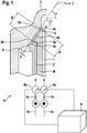
- a measuring mandrel M is the central element in the measuring system 6 according to the invention.
- the measuring mandrel has two measuring channels 1 and 2 which open into outlets 1a and 2a.
- the outlets 1a and 2a adjoin recesses 4a, 4b and 4c, which are formed as circumferential grooves in the surface of the measuring mandrel.
- the distance A between the two outlets 1a and 2a leads through the recess 4b.
- the measuring mandrel M is supported on the workpiece 3 by its three-leaf stop 5.
- the outlet 1a then lies opposite an area 1b on the workpiece surface.
- outlet 2a is one Area 2b on the workpiece surface opposite.
- the distance A between the two outlets is the area B on the workpiece surface.
- the shortest distance between the outlets 1a and 2a on the one hand and the workpiece surface 3 on the other hand is marked with the letter D.
- the measuring channel 1 is pressurized with compressed air via a pressure medium source 7a with a throttled outlet 7c.
- Compressed air as a pressure medium has the advantage that it does not have to be disposed of or returned to a reservoir after use.
- a pressure measuring device 8a is arranged between the throttled outlet 7c and the outlet 1a.
- the second measuring channel 2 is supplied with pressure by a pressure medium source 7b with a throttled outlet 7d.
- the pressure between the outlet 7d and the outlet 2a is measured with a second pressure measuring device 8b.
- the pressures measured by the two measuring devices 8a and 8b are fed to an evaluation unit 9, which determines the tilt angle between the distance A and the area B on the workpiece surface from the difference between the two pressures.
- the workpiece 3 examined has a conical bore with an opening angle a.
- the measuring mandrel M is also conical at its end with an opening angle ⁇ which corresponds to the target value for the angle ⁇ given during the production of the workpiece 3.
- the measured tilt angle ⁇ corresponds to the difference ⁇ - ⁇ between the actual value of the angle ⁇ and its target value ⁇ . He is in Figure 1 drawn very exaggerated.
Landscapes
- Physics & Mathematics (AREA)
- General Physics & Mathematics (AREA)
- Engineering & Computer Science (AREA)
- Mechanical Engineering (AREA)
- Measuring Arrangements Characterized By The Use Of Fluids (AREA)
- Measuring Fluid Pressure (AREA)
Claims (13)
- Jauge de contrainte pneumatique (M), comprenant un premier canal de mesure (1), qui peut être connecté à une source de fluide sous pression (7a, 7b) et qui débouche dans une première évacuation (1a) pour le fluide sous pression, pouvant être orientée vers la surface d'une pièce à contrôler (3), la jauge de contrainte (M) étant réalisée pour déterminer l'angle de basculement (α-β) entre une section (A) sur sa surface et une région (1b, 2b, B) opposée à cette section (A), sur la surface de la pièce (3), par le fait que la première évacuation (1a) est disposée au niveau d'une extrémité de la section (A) et par le fait que la première évacuation (1a) peut être déplacée à l'autre extrémité de la section (A) ou qu'au moins une deuxième évacuation (2a) est prévue, laquelle est disposée au niveau de l'autre extrémité de la section (A), caractérisée en ce que la jauge de contrainte est réalisée avec une symétrie de révolution.
- Jauge de contrainte pneumatique (M) selon la revendication 1, caractérisée en ce qu'un deuxième canal de mesure indépendant (2) est prévu, lequel débouche dans la deuxième évacuation (2a).
- Jauge de contrainte pneumatique selon l'une quelconque des revendications 1 et 2, caractérisée en ce qu'elle contient au moins un évidement (4a, 4b, 4c) dans lequel le fluide sous pression peut pénétrer à travers l'espace intermédiaire (D) entre la pièce (3) et l'évacuation (1a, 2a) et peut ensuite s'écouler sous forme non étranglée.
- Jauge de contrainte pneumatique (M) selon la revendication 3, caractérisée en ce que la section (A) conduit entre les deux évacuations (1a, 2a) par le biais d'au moins un évidement (4b).
- Jauge de contrainte pneumatique (M) selon l'une quelconque des revendications 1 à 4, caractérisée en ce qu 'elle présente au moins une butée (5) pour l'application contre la pièce (3).
- Jauge de contrainte pneumatique (M) selon l'une quelconque des revendications 1 à 5, caractérisée en ce qu'elle est réalisée en forme de cône au moins dans la région dans laquelle la section (A) s'étend entre les deux évacuations (1a) et (2a).
- Système de mesure (6) pour déterminer un angle (a-β) au niveau d'une surface d'une pièce (3), comprenant une jauge de contrainte pneumatique (M) selon l'une quelconque des revendications 1 à 6, au moins une source de fluide sous pression (7a, 7b) avec une sortie étranglée (7c, 7d), conduisant aux évacuations, ainsi qu'au moins un dispositif de mesure de pression (8a, 8b) monté entre la sortie et les évacuations.
- Système de mesure (6) selon la revendication 7, caractérisé en ce que des moyens sont prévus pour solliciter de manière alternée les deux évacuations (1a, 2a) avec le fluide sous pression.
- Système de mesure (6) selon l'une quelconque des revendications 7 et 8, caractérisé en ce que le dispositif de mesure de pression (8a, 8b) est connecté à une unité d'analyse (9) qui permet de déterminer l'angle (α-β) à partir des pressions mesurées.
- Procédé pour déterminer, de manière pneumatique, un angle de basculement (α-β) entre une section (A) dans l'espace et une région (1b, 2b, B) opposée à cette section (A) sur la surface d'une pièce à contrôler (3) avec une jauge de contrainte pneumatique (M) à symétrie de révolution, cette jauge de contrainte (M) présentant au moins un canal de mesure (1, 2) qui est sollicité avec un fluide sous pression par le biais d'une sortie étranglée (7c, 7d) d'une source de fluide sous pression (7a, 7b) et qui débouche dans une évacuation (1a, 2a) qui est orientée vers la surface de la pièce (3), la pression entre la sortie respective (7c, 7d) de la source de fluide sous pression (7a, 7b) et l'évacuation respective (1a, 2a) du canal de mesure (1, 2) étant mesurée au niveau des deux points d'extrémité de la section (A).
- Procédé selon la revendication 10, caractérisé en ce qu'une jauge de contrainte (M) ou un système de mesure (6) selon l'une quelconque des revendications 1 à 9 est sélectionné (e) pour sa mise en œuvre.
- Procédé selon l'une quelconque des revendications 10 et 11, caractérisé en ce que la section (A) est orientée dans l'espace jusqu'à un angle de 1 degré au maximum parallèlement à la surface de la pièce (3) .
- Procédé selon l'une quelconque des revendications 10 à 12, caractérisé en ce que le canal de mesure (1, 2) est sollicité avec une pression comprise entre 2 et 4 bar et l'évacuation (1a, 2a) au niveau de deux points de la section (A) est guidée à une distance comprise entre 10 µm et 40 µm, de préférence entre 20 µm et 30 µm, par rapport à la surface de la pièce (3).
Applications Claiming Priority (2)
| Application Number | Priority Date | Filing Date | Title |
|---|---|---|---|
| DE102014225169.9A DE102014225169A1 (de) | 2014-12-08 | 2014-12-08 | Pneumatischer Messdorn und Messsystem |
| PCT/EP2015/074888 WO2016091448A1 (fr) | 2014-12-08 | 2015-10-27 | Jauge-tampon pneumatique et système de mesure |
Publications (2)
| Publication Number | Publication Date |
|---|---|
| EP3230687A1 EP3230687A1 (fr) | 2017-10-18 |
| EP3230687B1 true EP3230687B1 (fr) | 2020-07-01 |
Family
ID=54360453
Family Applications (1)
| Application Number | Title | Priority Date | Filing Date |
|---|---|---|---|
| EP15786935.5A Active EP3230687B1 (fr) | 2014-12-08 | 2015-10-27 | Jauge-tampon pneumatique et procédé de mesure |
Country Status (4)
| Country | Link |
|---|---|
| US (1) | US10775162B2 (fr) |
| EP (1) | EP3230687B1 (fr) |
| DE (1) | DE102014225169A1 (fr) |
| WO (1) | WO2016091448A1 (fr) |
Family Cites Families (9)
| Publication number | Priority date | Publication date | Assignee | Title |
|---|---|---|---|---|
| DE1027414B (de) * | 1954-11-11 | 1958-04-03 | Andre Fortier | Pneumatisches Lehrenmessgeraet |
| SE505985C2 (sv) * | 1989-11-14 | 1997-10-27 | Amada Co Ltd | Sätt och anordning för avkänning av bockningsvinklar för en metallplåt under bockningen |
| US5148693A (en) * | 1989-11-14 | 1992-09-22 | Amada Company, Limited | Method and a device for detecting folding angles of a metal sheet during the folding and a method for folding of a metal sheet |
| DE3942207C2 (de) | 1989-12-21 | 1999-09-30 | Diatest Hermann Koeltgen Gmbh | Bohrungsmeßgerät |
| IT1260892B (it) * | 1993-02-23 | 1996-04-29 | Prima Ind Spa | Dispositivo per misurare l'angolo di un pezzo, in particolare l'angolodi piegatura di un pezzo di lamiera. |
| EP1083403A1 (fr) * | 1999-09-08 | 2001-03-14 | Bystronic Laser AG | Procédé et dispositif pour déterminer l'angle de pli d'un objet |
| EP1398094B1 (fr) * | 2002-09-11 | 2006-05-17 | Trumpf Werkzeugmaschinen GmbH + Co. KG | Procédé et dispositif pour déterminer la longueur de branche de pièces cintrées |
| DE10302055B4 (de) | 2003-01-21 | 2005-04-14 | Robert Bosch Gmbh | Interferometrische Messvorrichtung |
| DE102010026892A1 (de) * | 2010-04-09 | 2011-10-13 | Stotz Feinmesstechnik Gmbh | Vorrichtung zur Vermessung von Objekten |
-
2014
- 2014-12-08 DE DE102014225169.9A patent/DE102014225169A1/de not_active Withdrawn
-
2015
- 2015-10-27 WO PCT/EP2015/074888 patent/WO2016091448A1/fr not_active Ceased
- 2015-10-27 US US15/533,703 patent/US10775162B2/en not_active Expired - Fee Related
- 2015-10-27 EP EP15786935.5A patent/EP3230687B1/fr active Active
Non-Patent Citations (1)
| Title |
|---|
| None * |
Also Published As
| Publication number | Publication date |
|---|---|
| EP3230687A1 (fr) | 2017-10-18 |
| DE102014225169A1 (de) | 2016-06-09 |
| US10775162B2 (en) | 2020-09-15 |
| WO2016091448A1 (fr) | 2016-06-16 |
| US20170328707A1 (en) | 2017-11-16 |
Similar Documents
| Publication | Publication Date | Title |
|---|---|---|
| EP2876409B1 (fr) | Unité de mesure destinée à mesurer des forages | |
| EP3048414B1 (fr) | Installation de contrôle et procédé d'analyse d'un corps creux | |
| EP3289311B1 (fr) | Dispositif de mesure de la géométrie de la paroi intérieure de trous et procédé | |
| DE102007037683B3 (de) | Vorrichtungen und Verfahren zum Ermitteln der Lage einer Kante eines Werkstücks | |
| EP2093537A1 (fr) | Système et procédé pour déterminer l'alignement de deux pièces de machine rotatives, l'alignement de deux cylindres creux, ou pour éprouver la rectitude d'u component | |
| DE102007001620A1 (de) | Verfahren zum Betrieb einer Bearbeitungsmaschine sowie Werkzeughalterung | |
| EP3377846B1 (fr) | Mesure de planéité et mesure de longueur par voie tactile | |
| DE10322762A1 (de) | Halter für einen Rohling und Verfahren zur Vermessung der Lage und Orientierung des Halters | |
| EP3230687B1 (fr) | Jauge-tampon pneumatique et procédé de mesure | |
| EP1658470B1 (fr) | Systeme de mesure optique pour detecter des donnees geometriques relatives a des surfaces | |
| DE10319711B4 (de) | Verfahren zur hochgenauen dimensionalen Messung an Messobjekten | |
| DE10155135A1 (de) | Meßeinrichtung zur Bestimmung der Position eines Objektes relativ zu einer Bezugsfläche | |
| DE102022213730A1 (de) | Verfahren, Messanordnung und System zur Vermessung einer Innenkontur, insbesondere eines Innengewindes an einer Muffe oder einem Muffenende eines Rohres | |
| EP2053351A2 (fr) | Système de mesure, notamment pour la mesure de rainures | |
| DE19945717A1 (de) | Verfahren und Anordnung zur berürhrungslosen Erfassung der Lage, der Geometrie und der Abmessungen großer Bauteile | |
| DE102013215281A1 (de) | Pneumatische Messvorrichtung mit Lageausgleichanordnung | |
| WO2017125269A1 (fr) | Dispositif de mesure, système de mesure et procédé pour déterminer des signaux de mesure pendant un mouvement de pénétration d'un corps de pénétration dans une surface d'un échantillon | |
| DE102016115305A1 (de) | Koordinatenmessgerät | |
| DE102024115312B4 (de) | Messmaschine | |
| DE2046358C3 (de) | Meßeinrichtung für insbesondere zylindrische Bearbeitungsflächen von Werkstücken an Werkzeugmaschinen, insbesondere Honmaschinen | |
| DE102006044787B4 (de) | Messgerät für Hohlschaftkegel und Verfahren zum Vermessen eines Hohlschaftkegels | |
| DE102009021122A1 (de) | Verfahren zur Bearbeitung eines Werkstücks durch ein Werkzeug sowie Vorrichtung zur Durchführung des Verfahrens | |
| DE202005016616U1 (de) | Vorrichtung zur Überprüfung von Stufenbohrungen | |
| DE4101378A1 (de) | Vorrichtung zur feineinstellung der gegenseitigen lage zweier miteinander verbundener apparateteile | |
| DE1303821C2 (de) | Durchmessermesseinrichtung |
Legal Events
| Date | Code | Title | Description |
|---|---|---|---|
| STAA | Information on the status of an ep patent application or granted ep patent |
Free format text: STATUS: THE INTERNATIONAL PUBLICATION HAS BEEN MADE |
|
| PUAI | Public reference made under article 153(3) epc to a published international application that has entered the european phase |
Free format text: ORIGINAL CODE: 0009012 |
|
| STAA | Information on the status of an ep patent application or granted ep patent |
Free format text: STATUS: REQUEST FOR EXAMINATION WAS MADE |
|
| 17P | Request for examination filed |
Effective date: 20170710 |
|
| AK | Designated contracting states |
Kind code of ref document: A1 Designated state(s): AL AT BE BG CH CY CZ DE DK EE ES FI FR GB GR HR HU IE IS IT LI LT LU LV MC MK MT NL NO PL PT RO RS SE SI SK SM TR |
|
| AX | Request for extension of the european patent |
Extension state: BA ME |
|
| DAV | Request for validation of the european patent (deleted) | ||
| DAX | Request for extension of the european patent (deleted) | ||
| GRAP | Despatch of communication of intention to grant a patent |
Free format text: ORIGINAL CODE: EPIDOSNIGR1 |
|
| STAA | Information on the status of an ep patent application or granted ep patent |
Free format text: STATUS: GRANT OF PATENT IS INTENDED |
|
| INTG | Intention to grant announced |
Effective date: 20200319 |
|
| RAP1 | Party data changed (applicant data changed or rights of an application transferred) |
Owner name: ROBERT BOSCH GMBH |
|
| GRAS | Grant fee paid |
Free format text: ORIGINAL CODE: EPIDOSNIGR3 |
|
| GRAA | (expected) grant |
Free format text: ORIGINAL CODE: 0009210 |
|
| STAA | Information on the status of an ep patent application or granted ep patent |
Free format text: STATUS: THE PATENT HAS BEEN GRANTED |
|
| AK | Designated contracting states |
Kind code of ref document: B1 Designated state(s): AL AT BE BG CH CY CZ DE DK EE ES FI FR GB GR HR HU IE IS IT LI LT LU LV MC MK MT NL NO PL PT RO RS SE SI SK SM TR |
|
| REG | Reference to a national code |
Ref country code: CH Ref legal event code: EP Ref country code: AT Ref legal event code: REF Ref document number: 1286580 Country of ref document: AT Kind code of ref document: T Effective date: 20200715 |
|
| REG | Reference to a national code |
Ref country code: IE Ref legal event code: FG4D Free format text: LANGUAGE OF EP DOCUMENT: GERMAN |
|
| REG | Reference to a national code |
Ref country code: DE Ref legal event code: R096 Ref document number: 502015012933 Country of ref document: DE |
|
| REG | Reference to a national code |
Ref country code: LT Ref legal event code: MG4D |
|
| PG25 | Lapsed in a contracting state [announced via postgrant information from national office to epo] |
Ref country code: BG Free format text: LAPSE BECAUSE OF FAILURE TO SUBMIT A TRANSLATION OF THE DESCRIPTION OR TO PAY THE FEE WITHIN THE PRESCRIBED TIME-LIMIT Effective date: 20201001 |
|
| REG | Reference to a national code |
Ref country code: NL Ref legal event code: MP Effective date: 20200701 |
|
| PG25 | Lapsed in a contracting state [announced via postgrant information from national office to epo] |
Ref country code: SE Free format text: LAPSE BECAUSE OF FAILURE TO SUBMIT A TRANSLATION OF THE DESCRIPTION OR TO PAY THE FEE WITHIN THE PRESCRIBED TIME-LIMIT Effective date: 20200701 Ref country code: PT Free format text: LAPSE BECAUSE OF FAILURE TO SUBMIT A TRANSLATION OF THE DESCRIPTION OR TO PAY THE FEE WITHIN THE PRESCRIBED TIME-LIMIT Effective date: 20201102 Ref country code: LT Free format text: LAPSE BECAUSE OF FAILURE TO SUBMIT A TRANSLATION OF THE DESCRIPTION OR TO PAY THE FEE WITHIN THE PRESCRIBED TIME-LIMIT Effective date: 20200701 Ref country code: HR Free format text: LAPSE BECAUSE OF FAILURE TO SUBMIT A TRANSLATION OF THE DESCRIPTION OR TO PAY THE FEE WITHIN THE PRESCRIBED TIME-LIMIT Effective date: 20200701 Ref country code: ES Free format text: LAPSE BECAUSE OF FAILURE TO SUBMIT A TRANSLATION OF THE DESCRIPTION OR TO PAY THE FEE WITHIN THE PRESCRIBED TIME-LIMIT Effective date: 20200701 Ref country code: CZ Free format text: LAPSE BECAUSE OF FAILURE TO SUBMIT A TRANSLATION OF THE DESCRIPTION OR TO PAY THE FEE WITHIN THE PRESCRIBED TIME-LIMIT Effective date: 20200701 Ref country code: FI Free format text: LAPSE BECAUSE OF FAILURE TO SUBMIT A TRANSLATION OF THE DESCRIPTION OR TO PAY THE FEE WITHIN THE PRESCRIBED TIME-LIMIT Effective date: 20200701 Ref country code: NO Free format text: LAPSE BECAUSE OF FAILURE TO SUBMIT A TRANSLATION OF THE DESCRIPTION OR TO PAY THE FEE WITHIN THE PRESCRIBED TIME-LIMIT Effective date: 20201001 Ref country code: GR Free format text: LAPSE BECAUSE OF FAILURE TO SUBMIT A TRANSLATION OF THE DESCRIPTION OR TO PAY THE FEE WITHIN THE PRESCRIBED TIME-LIMIT Effective date: 20201002 |
|
| PG25 | Lapsed in a contracting state [announced via postgrant information from national office to epo] |
Ref country code: LV Free format text: LAPSE BECAUSE OF FAILURE TO SUBMIT A TRANSLATION OF THE DESCRIPTION OR TO PAY THE FEE WITHIN THE PRESCRIBED TIME-LIMIT Effective date: 20200701 Ref country code: RS Free format text: LAPSE BECAUSE OF FAILURE TO SUBMIT A TRANSLATION OF THE DESCRIPTION OR TO PAY THE FEE WITHIN THE PRESCRIBED TIME-LIMIT Effective date: 20200701 Ref country code: PL Free format text: LAPSE BECAUSE OF FAILURE TO SUBMIT A TRANSLATION OF THE DESCRIPTION OR TO PAY THE FEE WITHIN THE PRESCRIBED TIME-LIMIT Effective date: 20200701 Ref country code: IS Free format text: LAPSE BECAUSE OF FAILURE TO SUBMIT A TRANSLATION OF THE DESCRIPTION OR TO PAY THE FEE WITHIN THE PRESCRIBED TIME-LIMIT Effective date: 20201101 |
|
| PG25 | Lapsed in a contracting state [announced via postgrant information from national office to epo] |
Ref country code: NL Free format text: LAPSE BECAUSE OF FAILURE TO SUBMIT A TRANSLATION OF THE DESCRIPTION OR TO PAY THE FEE WITHIN THE PRESCRIBED TIME-LIMIT Effective date: 20200701 |
|
| REG | Reference to a national code |
Ref country code: DE Ref legal event code: R097 Ref document number: 502015012933 Country of ref document: DE |
|
| PG25 | Lapsed in a contracting state [announced via postgrant information from national office to epo] |
Ref country code: RO Free format text: LAPSE BECAUSE OF FAILURE TO SUBMIT A TRANSLATION OF THE DESCRIPTION OR TO PAY THE FEE WITHIN THE PRESCRIBED TIME-LIMIT Effective date: 20200701 Ref country code: SM Free format text: LAPSE BECAUSE OF FAILURE TO SUBMIT A TRANSLATION OF THE DESCRIPTION OR TO PAY THE FEE WITHIN THE PRESCRIBED TIME-LIMIT Effective date: 20200701 Ref country code: EE Free format text: LAPSE BECAUSE OF FAILURE TO SUBMIT A TRANSLATION OF THE DESCRIPTION OR TO PAY THE FEE WITHIN THE PRESCRIBED TIME-LIMIT Effective date: 20200701 Ref country code: DK Free format text: LAPSE BECAUSE OF FAILURE TO SUBMIT A TRANSLATION OF THE DESCRIPTION OR TO PAY THE FEE WITHIN THE PRESCRIBED TIME-LIMIT Effective date: 20200701 Ref country code: IT Free format text: LAPSE BECAUSE OF FAILURE TO SUBMIT A TRANSLATION OF THE DESCRIPTION OR TO PAY THE FEE WITHIN THE PRESCRIBED TIME-LIMIT Effective date: 20200701 |
|
| REG | Reference to a national code |
Ref country code: DE Ref legal event code: R119 Ref document number: 502015012933 Country of ref document: DE |
|
| PLBE | No opposition filed within time limit |
Free format text: ORIGINAL CODE: 0009261 |
|
| STAA | Information on the status of an ep patent application or granted ep patent |
Free format text: STATUS: NO OPPOSITION FILED WITHIN TIME LIMIT |
|
| PG25 | Lapsed in a contracting state [announced via postgrant information from national office to epo] |
Ref country code: AL Free format text: LAPSE BECAUSE OF FAILURE TO SUBMIT A TRANSLATION OF THE DESCRIPTION OR TO PAY THE FEE WITHIN THE PRESCRIBED TIME-LIMIT Effective date: 20200701 |
|
| REG | Reference to a national code |
Ref country code: CH Ref legal event code: PL |
|
| 26N | No opposition filed |
Effective date: 20210406 |
|
| GBPC | Gb: european patent ceased through non-payment of renewal fee |
Effective date: 20201027 |
|
| PG25 | Lapsed in a contracting state [announced via postgrant information from national office to epo] |
Ref country code: MC Free format text: LAPSE BECAUSE OF FAILURE TO SUBMIT A TRANSLATION OF THE DESCRIPTION OR TO PAY THE FEE WITHIN THE PRESCRIBED TIME-LIMIT Effective date: 20200701 Ref country code: LU Free format text: LAPSE BECAUSE OF NON-PAYMENT OF DUE FEES Effective date: 20201027 Ref country code: SK Free format text: LAPSE BECAUSE OF FAILURE TO SUBMIT A TRANSLATION OF THE DESCRIPTION OR TO PAY THE FEE WITHIN THE PRESCRIBED TIME-LIMIT Effective date: 20200701 |
|
| REG | Reference to a national code |
Ref country code: BE Ref legal event code: MM Effective date: 20201031 |
|
| PG25 | Lapsed in a contracting state [announced via postgrant information from national office to epo] |
Ref country code: DE Free format text: LAPSE BECAUSE OF NON-PAYMENT OF DUE FEES Effective date: 20210501 Ref country code: FR Free format text: LAPSE BECAUSE OF NON-PAYMENT OF DUE FEES Effective date: 20201031 |
|
| PG25 | Lapsed in a contracting state [announced via postgrant information from national office to epo] |
Ref country code: CH Free format text: LAPSE BECAUSE OF NON-PAYMENT OF DUE FEES Effective date: 20201031 Ref country code: BE Free format text: LAPSE BECAUSE OF NON-PAYMENT OF DUE FEES Effective date: 20201031 Ref country code: SI Free format text: LAPSE BECAUSE OF FAILURE TO SUBMIT A TRANSLATION OF THE DESCRIPTION OR TO PAY THE FEE WITHIN THE PRESCRIBED TIME-LIMIT Effective date: 20200701 Ref country code: LI Free format text: LAPSE BECAUSE OF NON-PAYMENT OF DUE FEES Effective date: 20201031 Ref country code: GB Free format text: LAPSE BECAUSE OF NON-PAYMENT OF DUE FEES Effective date: 20201027 |
|
| PG25 | Lapsed in a contracting state [announced via postgrant information from national office to epo] |
Ref country code: IE Free format text: LAPSE BECAUSE OF NON-PAYMENT OF DUE FEES Effective date: 20201027 |
|
| REG | Reference to a national code |
Ref country code: AT Ref legal event code: MM01 Ref document number: 1286580 Country of ref document: AT Kind code of ref document: T Effective date: 20201027 |
|
| PG25 | Lapsed in a contracting state [announced via postgrant information from national office to epo] |
Ref country code: AT Free format text: LAPSE BECAUSE OF NON-PAYMENT OF DUE FEES Effective date: 20201027 |
|
| PG25 | Lapsed in a contracting state [announced via postgrant information from national office to epo] |
Ref country code: TR Free format text: LAPSE BECAUSE OF FAILURE TO SUBMIT A TRANSLATION OF THE DESCRIPTION OR TO PAY THE FEE WITHIN THE PRESCRIBED TIME-LIMIT Effective date: 20200701 Ref country code: MT Free format text: LAPSE BECAUSE OF FAILURE TO SUBMIT A TRANSLATION OF THE DESCRIPTION OR TO PAY THE FEE WITHIN THE PRESCRIBED TIME-LIMIT Effective date: 20200701 Ref country code: CY Free format text: LAPSE BECAUSE OF FAILURE TO SUBMIT A TRANSLATION OF THE DESCRIPTION OR TO PAY THE FEE WITHIN THE PRESCRIBED TIME-LIMIT Effective date: 20200701 |
|
| PG25 | Lapsed in a contracting state [announced via postgrant information from national office to epo] |
Ref country code: MK Free format text: LAPSE BECAUSE OF FAILURE TO SUBMIT A TRANSLATION OF THE DESCRIPTION OR TO PAY THE FEE WITHIN THE PRESCRIBED TIME-LIMIT Effective date: 20200701 |