EP3230761B1 - Système et procédé pour fournir une prise de conscience de situation dynamique de menaces de radars d'attaque - Google Patents
Système et procédé pour fournir une prise de conscience de situation dynamique de menaces de radars d'attaque Download PDFInfo
- Publication number
- EP3230761B1 EP3230761B1 EP15839079.9A EP15839079A EP3230761B1 EP 3230761 B1 EP3230761 B1 EP 3230761B1 EP 15839079 A EP15839079 A EP 15839079A EP 3230761 B1 EP3230761 B1 EP 3230761B1
- Authority
- EP
- European Patent Office
- Prior art keywords
- aircraft
- attack radar
- incident power
- attack
- power values
- Prior art date
- Legal status (The legal status is an assumption and is not a legal conclusion. Google has not performed a legal analysis and makes no representation as to the accuracy of the status listed.)
- Active
Links
Images

Classifications
-
- G—PHYSICS
- G01—MEASURING; TESTING
- G01S—RADIO DIRECTION-FINDING; RADIO NAVIGATION; DETERMINING DISTANCE OR VELOCITY BY USE OF RADIO WAVES; LOCATING OR PRESENCE-DETECTING BY USE OF THE REFLECTION OR RERADIATION OF RADIO WAVES; ANALOGOUS ARRANGEMENTS USING OTHER WAVES
- G01S7/00—Details of systems according to groups G01S13/00, G01S15/00, G01S17/00
- G01S7/02—Details of systems according to groups G01S13/00, G01S15/00, G01S17/00 of systems according to group G01S13/00
- G01S7/36—Means for anti-jamming, e.g. ECCM, i.e. electronic counter-counter measures
-
- G—PHYSICS
- G01—MEASURING; TESTING
- G01S—RADIO DIRECTION-FINDING; RADIO NAVIGATION; DETERMINING DISTANCE OR VELOCITY BY USE OF RADIO WAVES; LOCATING OR PRESENCE-DETECTING BY USE OF THE REFLECTION OR RERADIATION OF RADIO WAVES; ANALOGOUS ARRANGEMENTS USING OTHER WAVES
- G01S5/00—Position-fixing by co-ordinating two or more direction or position line determinations; Position-fixing by co-ordinating two or more distance determinations
- G01S5/02—Position-fixing by co-ordinating two or more direction or position line determinations; Position-fixing by co-ordinating two or more distance determinations using radio waves
- G01S5/0249—Determining position using measurements made by a non-stationary device other than the device whose position is being determined
-
- G—PHYSICS
- G01—MEASURING; TESTING
- G01S—RADIO DIRECTION-FINDING; RADIO NAVIGATION; DETERMINING DISTANCE OR VELOCITY BY USE OF RADIO WAVES; LOCATING OR PRESENCE-DETECTING BY USE OF THE REFLECTION OR RERADIATION OF RADIO WAVES; ANALOGOUS ARRANGEMENTS USING OTHER WAVES
- G01S7/00—Details of systems according to groups G01S13/00, G01S15/00, G01S17/00
- G01S7/02—Details of systems according to groups G01S13/00, G01S15/00, G01S17/00 of systems according to group G01S13/00
- G01S7/021—Auxiliary means for detecting or identifying radar signals or the like, e.g. radar jamming signals
Definitions
- the present invention generally relates to radar warning receivers, and in particular to such receivers which provide a dynamic situational awareness of attack radar threats which would enhance the threat minimization for received attack radar signals.
- a coarse representation of range is displayed for attack radar signals.
- the range is estimated using the received power and the emitter equivalent radiated power listed in the mission data file.
- Such a range estimate is useful for a qualitative indication of whether or not the threat is within its lethal range, but cannot be reliably used for an accurate range determination.
- the accurate geolocation of the emitter has often not been available, either through lack of intelligence or through the lack of radar warning receiver capability.
- the determination of the incident power, which is the power impinging on the aircraft, from the received power, which is the power detected by the radar warning receiver has been hampered by the difficulty in obtaining an accurate determination of the installed receive antenna gain pattern. If these three issues could be resolved, dynamic situational awareness could be obtained that could assist in minimizing the threat associated with received radar signals.
- US 4 700 191A discloses a radar warning receiver for detecting and analyzing radar signals comprising a plurality of RF heads each tuned to a predetermined frequency band and connected to an antenna covering a preselected sector of reception of radar signals.
- Each of the heads includes a frequency converter converting the received signals to a common frequency base-band and producing an output signal in the base-band corresponding to the signal received by its antenna.
- the radar receiver also includes a central receiver unit receiving the signals from the RF heads, the central receiver unit comprising a plurality of channels, one of each RF head, for receiving and processing the signals from the respective head; and mode selector means for selectively switching the central receiver unit to operate according to: (a) an Acquisition Mode, wherein the plurality of channels are connected to cover contiguous sub-bands of the base-band; or (b) an Analysis Mode, wherein the plurality of channels are connected in parallel to cover the same sub-band of the base-band.
- EP 2 706 371 A2 discloses a method which includes receiving, at a vehicle navigation system, signal strength data indicating strength of a detected radar signal. The method also includes estimating a distance from a vehicle associated with the vehicle navigation system to a source of the detected radar signal based on the signal strength data. The method further includes generating a display that includes a graphical representation related to the source of the detected radar signal. The graphical representation related to the source of the detected radar signal is displayed in a manner that provides information regarding the estimated distance from the vehicle to the source.
- US 5 122 801 A discloses an aircraft threat monitoring system having several sensors responsive to a potential threat external to the aircraft such as a radar warning receiver, a radar sensor, a missile approach warning receiver, a forward-looking infrared detector and an electro-optic sensor.
- Each sensor has a respective inference processor the outputs of which are supplied to a groundspace map manager and an airspace map manager.
- the map managers collate the processor outputs to derive a threat output signal which is supplied to a planner programmed with tactical route information.
- the map managers also control operation of the sensors such as by modifying their sensitivity, scan or frequency in accordance with the output from other sensors.
- US 5 083 129 A discloses a police radar detector which detects the presence of radar signals incident upon a motor vehicle using the detector and also determines the direction of origin of the source of detected radar signals and signals the operator of the motor vehicle of the presence and source direction of the radar signals.
- the radar detector includes two antennas with shared circuitry in a single housing. One of the antennas is directed generally toward the front of the motor vehicle and the other antenna is directed generally to the rear of the motor vehicle.
- each potential radar signal which is detected is processed to determine the direction of origin of the signals.
- the signals are detected in both antennas with the signal strengths in the two antennas being compared to determine the direction of origin of the signals. It is preferred to identify the direction of the radar source as being to the front of the vehicle, to the rear of the vehicle or to the side of the vehicle.
- Empirically determined tables assist in the determination of thresholds for use in the detector to determine direction of the source of detected radar signals.
- US 5 151 701 A discloses a police radar detector which detects the presence of radar signals incident upon a motor vehicle using the detector and also determines the direction of origin of the source of detected radar signals and alerts the operator of the motor vehicle of the presence and source direction of the radar signals.
- the radar detector includes at least two antennas and preferably three or more antennas with detector circuitry shared among the antennas in a single detector housing.
- One of the antennas is directed generally toward the front of the motor vehicle and, for a three antenna embodiment, the second and third antennas are directed at angles of generally 120 DEG to the left and 120 DEG to the right of the front of the vehicle.
- the police speed radar frequency bands are scanned or swept, each potential radar signal which is detected is processed to determine the direction of origin of the signals.
- the signals are detected in all antennas with the signal strengths in the different antennas being compared to determine the direction of origin of the signals. It is preferred to identify the direction of the radar source as being to the front of the vehicle, to the rear of the vehicle, to the left side of the vehicle or to the right side of the vehicle.
- the present disclosure provides a method of reducing a threat from an attacking radar, comprising the steps of: receiving attack radar transmission signals over time at one or more antennas on an aircraft; identifying attack radar signals in the received attack radar transmission signals; measuring the received power at one or more antennas on the aircraft from the received attack radar transmission signals for each identified attack radar signal; calculating incident power values at one or more antennas on the aircraft from the received attack radar transmission signals for each identified attack radar signal; and characterized by further comprising the steps of: saving aircraft position data and the calculated incident power values as they change with time; calculating changes in the aircraft position and incident power values for the identified attack radar signals over time using the saved aircraft position data and incident power values; determining whether the aircraft is moving closer to, or away from, the center of the attack radar transmission signal beamwidth using the calculated changes in the incident power values and the aircraft position; and communicating a result of the determination whether the aircraft is moving closer to, or away from, the center of the attack radar transmission signal beamwidth to a pilot of the aircraft.
- the step of calculating changes in incident power may include compensating the measured received power for the gain pattern of each receive antenna.
- the step of compensating the measured received power may take into account the pitch, roll and yaw of the aircraft.
- the step of calculating where the aircraft is moving within the attack radar transmitter beamwidth may include determining the geolocation of the identified threat radar signal.
- the present disclosure provides a method of reducing the threat from an attacking radar with multiple aircraft, characterized by comprising the steps of: receiving attack radar transmission signals over time at one or more antennas on each of multiple aircraft; identifying attack radar signals in the received attack radar transmission signals of each aircraft; measuring the received power at one or more antennas on each aircraft from the received attack radar transmission signals for each identified attack radar signal; calculating incident power values at one or more antennas on each aircraft from the received attack radar transmission signals for each identified attack radar signal; saving each aircraft's position data and calculated incident power values as they change with time; calculating changes in each aircraft' s position and incident power values for the identified attack radar signals over time using the saved aircraft positions and incident power values; determining whether each aircraft is moving closer to or farther away from a center of the attack radar transmission signal beamwidth using the calculated changes in their respective incident power values and positions, and comparing where each aircraft is located within the attack radar transmission signal beamwidth using the respective calculated incident power values and positions.
- the method may further comprise comparing the incident powers among the aircraft.
- the method may still further comprise communicating and sharing incident power values and information regarding where each aircraft is within the attack radar transmitter beamwidth among the aircraft.
- the step of calculating changes in incident power may include compensating the measured received power for a reception gain pattern for each antenna on each aircraft.
- the step of compensating the measured received power may take into account the pitch, roll and yaw of each aircraft.
- the method may further comprise determining a transmission geolocation for the identified attack radar signal.
- the present disclosure provides a system for reducing a threat from an attacking radar, comprising: circuitry adapted for receiving radar transmission signals over time at one or more antennas on an aircraft; circuitry adapted for determining a position and attitude of the aircraft; a processor; memory for storing data and including code representing instructions that when executed cause the processor to: identify attack radar signals in the received attack radar transmission signals; measure received power at one or more antennas on the aircraft from the received attack radar transmission signals for each identified attack radar signal; calculate incident power values at one or more antennas on the aircraft from the received attack radar transmission signals for each identified attack radar signal, save aircraft position data and the calculated incident power values as they change over time, calculate changes in the aircraft position and incident power for the identified attack radar signals over time using the saved aircraft position data and incident power values; and determine whether the aircraft is moving closer to, or away from, the center of the attack radar transmission signal beamwidth using the calculated changes in the incident power and the aircraft position; and means for providing an indicator for controlling aircraft functions in response to a result of the determination whether the ari
- the code representing instructions which when executed causes the processor to calculate changes in incident power may also cause the processor to compensate the measured received power for the gain pattern for each antenna.
- the code representing instructions which when executed causes the processor to compensate the measured received power may also cause the processor to take into account pitch, roll and yaw of the aircraft.
- the memory may include code representing instructions that when executed cause the processor to determine the transmission geolocation of the identified attack radar signal.
- the present disclosure provides a system for reducing threat from an attacking radar, comprising: circuitry adapted for receiving attack radar transmission signals over time at one or more antennas on each aircraft of multiple aircraft; circuitry adapted for determining a position and attitude of each aircraft; a processor on each aircraft; memory on each aircraft for storing data and including code representing instructions that when executed cause the processor to: identify attack radar signals in the received attack radar transmission signals; measure received power at one or more antennas on each aircraft from the received attack radar transmission signals for each identified attack radar signal; calculate incident power values at one or more antennas on each aircraft from the received attack radar transmission signals for each identified attack radar signal, save aircraft position data and the calculated incident power values on each aircraft as they change with time, calculate changes in each aircraft's position and incident power for the identified attack radar signals over time using the saved aircraft position data and incident power values; determine whether each aircraft is moving closer to or farther away from a center of the attack radar transmission signal beamwidth using the calculated changes in the saved incident power values and the saved aircraft position data; compare the incident power values between aircraft
- the code representing instructions which when executed causes each aircraft's processor to calculate changes in each aircrafts position and changes in incident power may also cause the processor to compensate the measured received power for the gain pattern for each antenna.
- the code representing instructions which when executed causes each aircraft's processor to compensate the measured received power may also take into account pitch, roll and yaw of the aircraft.
- the memory may include code representing instructions that when executed cause the processor to determine the transmission geolocation of the identified attack radar signal.
- the memory code may also cause the processor to communicate and share incident power information and information regarding where each aircraft is within the attack radar transmitter beamwidth among the aircraft.
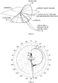
- Fig. 1 depicts an aircraft 10 that is currently within the beam 12 of an intercepting radar.
- the width 14 of beam 12 at typical distances is of the order of kilometers.
- a typical time that a tactical aircraft might take to traverse a stationary beam is on the order of tens of seconds.
- a typical time that it takes for an electronic countermeasure to be effective may also be on the order of tens of seconds.
- information on where the aircraft is with respect to the intercepting radar beam can assist the pilot to take action to minimize exposure to the intercepting radar.
- Signals in the radar signal spectrum are typically received by one or more antennas 16, 18 on an aircraft 10 as shown in Fig. 2 .
- the signals are digitized and stored for analysis by a radar warning receiver (RWR), not shown.
- RWR radar warning receiver
- the power density received by an antenna is denoted herein as P rec and the power density incident on the airplane is denoted herein as P inc .
- the incident power is the power impinging on the aircraft and is independent of the aircraft orientation and the receive antenna beam pattern.
- the determination of how the incident power is changing gives an indication of the location of the aircraft within the beam.
- G is the emitter antenna gain, which is a function of its local angular coordinates referenced to its location with respect to the aircraft
- P 0 is the transmit power of the emitter.
- F expresses the effects of the antenna beam functions of the receiving antennas.
- F is a function of the orientation of the aircraft with respect to the emitter line of sight direction.
- G the value of the emitter gain
- the first factor on the right hand side of Eq. (3) is directly measured by the RWR.
- the second factor uses the location of the emitter.
- the third factor uses knowledge of the emitter line of sight unit vector, (i.e. geolocation), and also requires precise knowledge of the aircraft installed antenna beam patterns.
- the G ratios of Eq. (3) are continually measured and computed as the airplane maneuvers.
- the G ratios are tracked in a filter to drive down the random errors.
- the range and emitter line of sight vector information can be used with Eq. (2) to determine where the aircraft is within the scanning beam of a radar in search mode.
- the pilot may be able to use this information to make sure that his aircraft stays sufficiently outside the main portion of the search beam to avoid detection.
- Fig. 4 shows another situational schematic of either two aircraft 32, 34 within different portions an attack radar beam, or different possible locations of an aircraft within a beam.
- Aircraft 32 represents a location within a high incident power beam portion 33 of emitter 31, while aircraft 34 represents a location within a low incident power beam portion 35.
- the attack radar location is not known and a scanning or tracking radar is detected, the pilot could initiate a geolocation determination and G ratio track and then attempt to either maneuver the aircraft outside of the main beam or initiate a countermeasure or both. In this manner, aircraft 34 might change course to avoid heading directly towards emitter 31 and intersecting the high incident power beam portion 33.
- the pilot can monitor the success or failure of his maneuver/countermeasures with a display indication driven by the G ratio value and make real time adjustments accordingly.
- Possibilities for displaying the G ratio information include variable intensity or variable color display of the threat symbol. Alternatively, a numerical indication of the G ratio may be displayed. Displaying a history or G values may also be useful.
- the display may contain more detailed information. If the attack radar has been identified and geolocated and the determination of G via Eq. (2) indicates that the aircraft is in the middle of high incident power beam portion 33, then we may be able to display the beamwidth of the radar beam. This could be done as a pair of short lines on a map display showing the azimuthal extent of the beam at the position of the aircraft and a pair of altitudes indicating the elevation extent of the beam. If the pilot decides to maneuver, then one can make the assumption that the attack radar will lag in its response to the maneuver and the G ratio can be used to monitor the aircraft position within the beamwidth.
- the G ratio can be used to monitor whether the beam moves towards the chaff or decoy and the display can be updated accordingly. If the pilot decides to initiate a jamming technique such as a velocity gate pull off, the G ratio can be used to determine if the technique successfully caused the expected advance or retardation of the radar track.
- TDOA time difference of arrival
- FDOA frequency difference of arrival
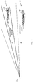
- an aircraft 10 is receiving a pulsed signal on two of its receiving antennas.
- 1 c
- b ⁇ ⁇ R ⁇ c for
- This equation describes an equation for the angle between b and R ⁇ since we know b and we measure ⁇ .
- the line of sight vector, R ⁇ lies on a TDOA cone 22 centered about b with this angle equal to the cone angle. Taking the time derivative of Eq.
- v is the aircraft velocity.
- the line of sight vector lines on a dTDOA or FDOA cone 24 centered about the known vector defined in the square brackets.
- the intersection of the TDOA cone 22 and dTDOA cone 24 determines the line of sight vector.
- the intersection of the line of sight vector with the earth determines the latitude and longitude of the ground emitter. This is illustrated in Fig. 3 .
- the intersection of the two cones results in two lines 30.
- the ambiguity is easily resolved from coarse angle of arrival measurements or other means.
- the errors associated with Eqs. (4) and (5) are driven down with a tracking technique such as a Kalman filter or a least squares optimization technique.
- Fig. 5 shows the difference between a measured antenna pattern 36 and a simulated pattern 38. Compensation may also be made for installed aircraft equipment and even for control surface movement.
Landscapes
- Engineering & Computer Science (AREA)
- Radar, Positioning & Navigation (AREA)
- Remote Sensing (AREA)
- Physics & Mathematics (AREA)
- General Physics & Mathematics (AREA)
- Computer Networks & Wireless Communication (AREA)
- Radar Systems Or Details Thereof (AREA)
Claims (15)
- Procédé de réduction d'une menace provenant d'un radar d'attaque, comprenant les étapes consistant en :la réception de signaux d'émission de radar d'attaque au fil du temps au niveau d'une ou plusieurs antennes (16, 18) sur un aéronef (10) ;l'identification de signaux de radar d'attaque dans les signaux d'émission de radar d'attaque reçus ;la mesure de valeurs de puissance incidente au niveau d'une ou plusieurs antennes (16, 18) sur l'aéronef (10) provenant des signaux d'émission de radar d'attaque reçus pour chaque signal de radar d'attaque identifié ;le calcul de valeurs de puissance incidente au niveau d'une ou plusieurs antennes (16, 18) sur l'aéronef (10) provenant des signaux d'émission de radar d'attaque reçus pour chaque signal de radar d'attaque identifié ; etcaractérisé en ce qu'il comprend en outre les étapes consistant en :la sauvegarde, au fur et à mesure qu'elles changent avec le temps, des données de position de l'aéronef et des valeurs de puissance incidente calculées ;le calcul de changements dans la position de l'aéronef et des valeurs de puissance incidente des signaux de radar d'attaque identifiés au fil du temps à l'aide des données de position de l'aéronef et des valeurs de puissance incidente sauvegardées ;la détermination du fait que l'aéronef se rapproche, ou s'éloigne, du centre de la largeur de faisceau du signal d'émission du radar d'attaque (14) à l'aide des changements calculés des valeurs de puissance incidente et de la position de l'aéronef ; etla communication d'un résultat de la détermination pour savoir si l'aéronef (10) se rapproche, ou s'éloigne, du centre de la largeur de faisceau du signal d'émission de radar d'attaque (14) à un pilote de l'aéronef.
- Procédé de la revendication 1, l'étape de calcul de changements dans les valeurs de puissance incidente comprenant la compensation de la puissance reçue mesurée pour le motif de gain de réception de chaque antenne de réception (16, 18) ; et
de préférence, l'étape de compensation de la puissance reçue mesurée prenant en compte le tangage, le roulis et le lacet de l'aéronef (10). - Procédé de la revendication 1, l'étape consistant à déterminer si l'aéronef (10) se rapproche, ou s'éloigne, du centre de la largeur de faisceau du signal d'émission du radar d'attaque (14) comprenant la détermination d'une géolocalisation d'un émetteur (20) du signal du radar d'attaque identifié.
- Procédé de réduction de la menace provenant d'un radar d'attaque à l'aide de multiples aéronefs (32, 34), caractérisé en ce qu'il comprend les étapes consistant à :recevoir des signaux d'émission d'un radar d'attaque au fil du temps par une ou plusieurs antennes sur chacun des multiples aéronefs (32, 34) ;identifier des signaux de radar d'attaque dans les signaux d'émission de radar d'attaque reçus de chaque aéronef (32, 34) ;mesurer la puissance reçue par une ou plusieurs antennes sur chaque aéronef (32, 34) provenant des signaux d'émission de radar d'attaque reçus pour chaque signal de radar d'attaque identifié ;calculer des valeurs de puissance incidente au niveau d'une ou plusieurs antennes sur chaque aéronef (32, 34) provenant des signaux d'émission de radar d'attaque reçus pour chaque signal de radar d'attaque identifié ;sauvegarder des données de position de chaque aéronef et des valeurs de puissance incidente calculées au fur et à mesure qu'elles changent avec le temps ;calculer des changements de position de chaque aéronef et des valeurs de puissance incidente pour les signaux de radar d'attaque identifiés au fil du temps à l'aide des données de position de l'aéronef et des valeurs de puissance incidente sauvegardées ;déterminer que chaque aéronef (32, 34) se rapproche, ou s'éloigne, du centre (33) de la largeur de faisceau du signal d'émission du radar d'attaque (33, 35) à l'aide des changements calculés dans leurs valeurs de puissance incidente et positions respectives, etcomparer l'emplacement de chaque aéronef (32, 34) à l'intérieur de la largeur de faisceau du signal d'émission du radar d'attaque (33, 35) à l'aide des valeurs de puissance incidente et positions calculées respectives.
- Procédé de la revendication 4, comprenant en outre la comparaison des valeurs de puissance incidente parmi les multiples aéronefs (32, 34).
- Procédé de la revendication 4, comprenant en outre la communication et le partage entre les multiples aéronefs (32, 34) des valeurs de puissance incidente et des informations concernant l'emplacement de chaque aéronef (32, 34) à l'intérieur de la largeur de faisceau de signal d'émission du radar d'attaque (33, 35).
- Procédé de la revendication 4, l'étape de calcul de changements dans les valeurs de puissance incidente consistant à compenser les changements mesurés pour un motif de gain de réception de chaque antenne de réception sur chaque aéronef (32, 34) ; et
de préférence, l'étape de compensation de la puissance reçue mesurée prenant en compte le tangage, le roulis et le lacet de chaque aéronef (32, 34). - Procédé de la revendication 4, comprenant en outre la détermination d'une géolocalisation d'un émetteur (31) du signal du radar d'attaque identifié.
- Système pour la réduction d'une menace provenant d'un radar d'attaque, comprenant :des circuits conçus pour recevoir des signaux d'émission radar au fil du temps au niveau d'une ou plusieurs antennes (16,18) sur un aéronef (10) ;des circuits conçus pour déterminer une position et une attitude de l'aéronef (10) ;un processeur ;une mémoire pour stocker des données et comprenant un code représentant des instructions qui, lorsqu'elles sont exécutées, amènent le processeur à :identifier des signaux de radar d'attaque dans les signaux d'émission de radar d'attaque reçus ;mesurer la puissance reçue par une ou plusieurs antennes (16,18) sur l'aéronef (10) provenant des signaux d'émission de radar d'attaque reçus pour chaque signal de radar d'attaque identifié ;calculer les valeurs de puissance incidente au niveau d'une ou plusieurs antennes (16,18) sur l'aéronef (10) provenant des signaux d'émission de radar d'attaque reçus pour chaque signal de radar d'attaque identifié, sauvegarder les données de position de l'aéronef et les valeurs de puissance incidente calculées au fur et à mesure qu'elles changent au fil du temps, calculer les changements de la position de l'aéronef et de la puissance incidente pour les signaux de radar d'attaque identifiés au fil du temps à l'aide des données de position de l'aéronef et des valeurs de puissance incidente sauvegardées ; etdéterminer si l'aéronef (10) se rapproche, ou s'éloigne, du centre de la largeur de faisceau du signal d'émission du radar d'attaque (14) à l'aide des changements calculés des valeurs de puissance incidente et de la position de l'aéronef ; etdes moyens pour fournir un indicateur pour commander des fonctions de l'aéronef en réponse à un résultat de la détermination si l'aéronef (10) se rapproche, ou s'éloigne, du centre de la largeur de faisceau du signal d'émission du radar d'attaque (14) pour permettre à un pilote de manoeuvrer l'aéronef (10) et/ou d'engager des contre-mesures électroniques pour réduire la menace du radar d'attaque identifiée.
- Système de la revendication 9, le code représentant des instructions qui, lorsqu'elles sont exécutées, amènent le processeur à calculer des changements dans les valeurs de puissance incidente et amènent également le processeur à compenser la puissance reçue mesurée pour le motif de gain de réception de chaque antenne de réception (16, 18) ; et
de préférence, le code représentant des instructions qui, lorsqu'elles sont exécutées, amènent le processeur à compenser la puissance reçue mesurée, et amènent également le processeur à prendre en compte le tangage, le roulis et le lacet de l'aéronef (10). - Système de la revendication 9, la mémoire comprenant un code représentant des instructions qui, lorsqu'elles sont exécutées, amènent le processeur à déterminer une géolocalisation d'un émetteur (20) du signal de radar d'attaque identifié.
- Système pour la réduction d'une menace provenant d'un radar d'attaque, comprenant :des circuits conçus pour recevoir des signaux d'émission de radar d'attaque au fil du temps au niveau d'une ou plusieurs antennes sur chaque aéronef (32,34) de multiples aéronefs (32, 34) ;des circuits conçus pour déterminer une position et une attitude de chaque aéronef (32, 34) ;un processeur sur chaque aéronef (32, 34) ;une mémoire sur chaque aéronef (32, 34) pour stocker des données et comprenant un code représentant des instructions qui, lorsqu'elles sont exécutées, amènent le processeur à :identifier des signaux de radar d'attaque dans les signaux d'émission de radar d'attaque reçus ;mesurer la puissance reçue par une ou plusieurs antennes sur chaque aéronef (32, 34) provenant des signaux d'émission de radar d'attaque reçus pour chaque signal de radar d'attaque identifié ;calculer les valeurs de puissance incidente au niveau d'une ou plusieurs antennes sur chaque aéronef (32,34) provenant des signaux d'émission de radar d'attaque reçus pour chaque signal de radar d'attaque identifié, sauvegarder des données de position de l'aéronef et les valeurs de puissance incidente calculées sur chaque aéronef (32,34) au fur et à mesure qu'elles changent au cours du temps, calculer des changements dans la position de chaque aéronef et la puissance incidente pour l'aéronef des signaux de radar d'attaque identifiés au fil du temps à l'aide des données de position de l'aéronef sauvegardées et des valeurs de puissance incidente ;déterminer si chaque aéronef (32, 34) se rapproche, ou s'éloigne, du centre (33) de la largeur de faisceau du signal d'émission du radar d'attaque (33, 35) à l'aide des changements calculés dans les valeurs de puissance incidente et des données de position de l'aéronef sauvegardées ;comparer les valeurs de puissance incidente entre aéronefs ;comparer l'emplacement de chaque aéronef (32, 34) à l'intérieur de la largeur de faisceau du signal d'émission du radar d'attaque (33, 35) à l'aide des valeurs de puissance incidente et positions calculées et des positions de l'aéronef respectives; etdes moyens pour fournir un indicateur sur chaque aéronef pour commander des fonctions de l'aéronef en réponse à un résultat de la comparaison de l'emplacement de chaque aéronef (32, 34) à l'intérieur de la largeur de faisceau du signal d'émission du radar d'attaque (33, 35) pour permettre à un pilote de manoeuvrer un aéronef (32, 34) et/ou d'engager des contre-mesures électroniques pour réduire au minimum une menace radar identifiée.
- Système de la revendication 12, le code représentant des instructions qui, lorsqu'elles sont exécutées, amènent le processeur de chaque aéronef à calculer des changements de position de chaque aéronef et des changements dans les valeurs de puissance incidente et amènent également le processeur à compenser la puissance reçue mesurée pour un motif de gain de réception de chaque antenne ; et
de préférence, le code représentant des instructions qui, lorsqu'elles sont exécutées, amènent le processeur de chaque aéronef à compenser la puissance reçue mesurée, et également à prendre en compte le tangage, le roulis et le lacet de l'aéronef (32, 34). - Système de la revendication 12, la mémoire comprenant un code représentant des instructions qui, lorsqu'elles sont exécutées, amènent le processeur à déterminer une géolocalisation d'un émetteur (31) du signal de radar d'attaque identifié.
- Système de la revendication 12, la mémoire comprenant un code représentant des instructions qui, lorsqu'elles sont exécutées, amènent également le processeur à communiquer et à partager, parmi les aéronefs (32, 34), des informations de puissance incidente et des informations concernant l'emplacement de chaque aéronef (32, 34) à l'intérieur de la largeur de faisceau de signal d'émission du radar d'attaque (33, 35).
Applications Claiming Priority (2)
| Application Number | Priority Date | Filing Date | Title |
|---|---|---|---|
| US14/566,830 US9753123B2 (en) | 2014-12-11 | 2014-12-11 | System and method to provide a dynamic situational awareness of attack radar threats |
| PCT/US2015/045050 WO2016093899A1 (fr) | 2014-12-11 | 2015-08-13 | Système et procédé pour fournir une prise de conscience de situation dynamique de menaces de radars d'attaque |
Publications (2)
| Publication Number | Publication Date |
|---|---|
| EP3230761A1 EP3230761A1 (fr) | 2017-10-18 |
| EP3230761B1 true EP3230761B1 (fr) | 2019-05-29 |
Family
ID=55442853
Family Applications (1)
| Application Number | Title | Priority Date | Filing Date |
|---|---|---|---|
| EP15839079.9A Active EP3230761B1 (fr) | 2014-12-11 | 2015-08-13 | Système et procédé pour fournir une prise de conscience de situation dynamique de menaces de radars d'attaque |
Country Status (7)
| Country | Link |
|---|---|
| US (1) | US9753123B2 (fr) |
| EP (1) | EP3230761B1 (fr) |
| CA (1) | CA2970282C (fr) |
| DK (1) | DK3230761T3 (fr) |
| IL (1) | IL252545B (fr) |
| TR (1) | TR201909022T4 (fr) |
| WO (1) | WO2016093899A1 (fr) |
Families Citing this family (3)
| Publication number | Priority date | Publication date | Assignee | Title |
|---|---|---|---|---|
| RU2743479C1 (ru) * | 2020-03-25 | 2021-02-18 | Акционерное общество "Концерн радиостроения "Вега" | Способ и система определения наиболее благоприятных для атаки воздушных целей в режиме многоцелевого сопровождения |
| TR2022015010A1 (tr) * | 2022-09-30 | 2024-04-22 | Tusas Tuerk Havacilik Ve Uzay Sanayii Anonim Sirketi | Bir hareket sistemi. |
| CN117572091B (zh) * | 2023-11-16 | 2024-08-06 | 扬州宇安电子科技股份有限公司 | 一种机载侦测高性能小型化告警系统 |
Family Cites Families (43)
| Publication number | Priority date | Publication date | Assignee | Title |
|---|---|---|---|---|
| US5426434A (en) * | 1970-09-03 | 1995-06-20 | Bishop; Walton B. | Semiautomatic jam-accept (SAJAC) decider for mode-4 of the IFF mark XII |
| US5245347A (en) * | 1980-12-29 | 1993-09-14 | Raytheon Company | All weather tactical strike system (AWTSS) and method of operation |
| IL74887A (en) * | 1985-04-14 | 1989-06-30 | Dan Manor | Radar warning receiver |
| US7741991B1 (en) * | 1987-06-26 | 2010-06-22 | Mbda Uk Limited | Radar tracking system |
| GB8919151D0 (en) | 1989-08-23 | 1990-04-25 | Smiths Industries Plc | Monitoring systems |
| US5638281A (en) * | 1991-01-31 | 1997-06-10 | Ail Systems, Inc. | Target prediction and collision warning system |
| US5083129A (en) | 1991-02-25 | 1992-01-21 | Valentine Research, Inc. | Police radar detector for detecting radar signals and determining the directional origin of the signal source |
| US5151701A (en) | 1991-02-25 | 1992-09-29 | Valentine Research, Inc. | Police radar detectors for detecting radar signals and determining the directional origin of the signal source |
| US5406286A (en) * | 1992-11-17 | 1995-04-11 | Honeywell Inc. | Real time passive threat positioning system |
| US5457460A (en) * | 1992-11-17 | 1995-10-10 | Honeywell Inc. | Embedded threat data recorder |
| US5451956A (en) * | 1993-08-20 | 1995-09-19 | Trw Inc. | Instantaneous parameter measuring receiver |
| DE19609613A1 (de) * | 1996-03-12 | 1997-09-18 | Vdo Luftfahrtgeraete Werk Gmbh | Verfahren zur Erkennung eines Kollisionsrisikos und zur Vermeidung von Kollisionen in der Luftfahrt |
| DE19745370A1 (de) * | 1996-10-16 | 1998-04-23 | Edgar Grassmann | Verfahren und Vorrichtung zur Bestimmung einfallender Empfangsleistung oder -energie wenigstens eines Signales in wenigstens einer vorgebbaren Beobachtungsrichtung sowie Empfangsanlage |
| US6639545B1 (en) * | 2002-05-13 | 2003-10-28 | Honeywell International Inc. | Methods and apparatus to determine a target location in body coordinates |
| US6744401B2 (en) * | 2002-05-13 | 2004-06-01 | Honeywell International Inc. | Methods and apparatus for radar data processing |
| US7068209B2 (en) * | 2002-11-18 | 2006-06-27 | Lockheed Martin Corporation | System and method for detecting and jamming emitter signals |
| US7132928B2 (en) * | 2003-10-01 | 2006-11-07 | Perricone Nicholas V | Threat detection system interface |
| US7038618B2 (en) * | 2004-04-26 | 2006-05-02 | Budic Robert D | Method and apparatus for performing bistatic radar functions |
| US6980151B1 (en) * | 2004-06-14 | 2005-12-27 | General Dynamics Advanced Information Systems, Inc. | System and method for onboard detection of ballistic threats to aircraft |
| US7221307B1 (en) * | 2004-07-08 | 2007-05-22 | Lockheed Martin Corporation | Determination of the presence of closely spaced targets |
| US20060169832A1 (en) * | 2005-01-06 | 2006-08-03 | Glasson Richard O | Rocket propelled barrier defense system |
| US7212148B1 (en) * | 2005-04-05 | 2007-05-01 | Itt Manufacturing Enterprises, Inc. | Apparatus for jamming infrared attack unit using a modulated radio frequency carrier |
| US7292178B1 (en) * | 2005-07-28 | 2007-11-06 | Rockwell Collins, Inc. | Aircraft hazard detection and alerting in terminal areas |
| US7504982B2 (en) * | 2005-12-06 | 2009-03-17 | Raytheon Company | Anti-Missile system and method |
| US8084724B1 (en) * | 2006-02-01 | 2011-12-27 | Raytheon Company | Enhanced multiple kill vehicle (MKV) interceptor for intercepting exo and endo-atmospheric targets |
| US7977614B2 (en) * | 2006-09-03 | 2011-07-12 | E.C.S. Engineering Consulting Services-Aerospace Ltd. | Method and system for defense against incoming rockets and missiles |
| IL178221A0 (en) * | 2006-09-20 | 2008-01-20 | Elta Systems Ltd | Active protection method and system |
| AU2008287308B2 (en) * | 2007-05-14 | 2011-05-26 | Raytheon Company | Methods and apparatus for selecting a target from radar tracking data |
| US7609200B1 (en) * | 2007-05-29 | 2009-10-27 | Rockwell Collins, Inc. | Radar derived perspective display system |
| EP2158439B1 (fr) * | 2007-06-08 | 2018-11-28 | Raytheon Company | Procédé et appareil d'interception d'un projectile |
| US7696919B2 (en) * | 2008-01-03 | 2010-04-13 | Lockheed Martin Corporation | Bullet approach warning system and method |
| US8536500B2 (en) * | 2008-08-07 | 2013-09-17 | Cpi Ip, Llc | System and method for rapid aiming and firing of defensive countermeasures |
| US8639394B2 (en) * | 2008-12-01 | 2014-01-28 | Lockheed Martin Corporation | Dynamic optical countermeasures for ground level threats to an aircraft |
| FR2940686B1 (fr) * | 2008-12-30 | 2011-03-18 | Thales Sa | Procede et systeme de localisation d'une cible dans un systeme interrogation reponse (iff). |
| IL197522A (en) * | 2009-03-10 | 2013-10-31 | Bird Aerosystems Ltd | A system and method for protecting aircraft from assault |
| US8279109B1 (en) * | 2009-03-30 | 2012-10-02 | Gregory Hubert Piesinger | Aircraft bird strike avoidance method and apparatus using transponder |
| GB2478529B (en) * | 2010-03-08 | 2013-08-21 | Cantor Internat Ltd | Processing radio signals to minimise interference effects |
| GB2479211B (en) * | 2010-03-31 | 2014-07-23 | Qinetiq Ltd | System for the detection of incoming munitions |
| EP2390616A1 (fr) * | 2010-05-27 | 2011-11-30 | Nederlandse Organisatie voor toegepast -natuurwetenschappelijk onderzoek TNO | Procédé de guidage d'une salve de projectiles guidés vers une cible, système et produit de programme informatique |
| IL213125A0 (en) * | 2011-05-24 | 2011-10-31 | Bird Aerosystems Ltd | System, device and method of protecting aircrafts against incoming missiles and threats |
| KR101295643B1 (ko) * | 2011-11-02 | 2013-08-12 | 한국전자통신연구원 | Gps 신호 수신 장치 및 그 방법 |
| US8744390B2 (en) * | 2012-03-29 | 2014-06-03 | Adc Telecommunications, Inc. | Systems and methods for adjusting system tests based on detected interference |
| US9007255B2 (en) * | 2012-09-07 | 2015-04-14 | The Boeing Company | Display of information related to a detected radar signal |
-
2014
- 2014-12-11 US US14/566,830 patent/US9753123B2/en active Active
-
2015
- 2015-08-13 EP EP15839079.9A patent/EP3230761B1/fr active Active
- 2015-08-13 TR TR2019/09022T patent/TR201909022T4/tr unknown
- 2015-08-13 CA CA2970282A patent/CA2970282C/fr active Active
- 2015-08-13 WO PCT/US2015/045050 patent/WO2016093899A1/fr not_active Ceased
- 2015-08-13 DK DK15839079.9T patent/DK3230761T3/da active
-
2017
- 2017-05-28 IL IL252545A patent/IL252545B/en active IP Right Grant
Non-Patent Citations (1)
| Title |
|---|
| None * |
Also Published As
| Publication number | Publication date |
|---|---|
| EP3230761A1 (fr) | 2017-10-18 |
| DK3230761T3 (da) | 2019-06-24 |
| CA2970282A1 (fr) | 2016-06-16 |
| CA2970282C (fr) | 2021-08-03 |
| IL252545B (en) | 2018-05-31 |
| US20160349355A1 (en) | 2016-12-01 |
| TR201909022T4 (tr) | 2019-07-22 |
| WO2016093899A1 (fr) | 2016-06-16 |
| IL252545A0 (en) | 2017-07-31 |
| US9753123B2 (en) | 2017-09-05 |
Similar Documents
| Publication | Publication Date | Title |
|---|---|---|
| CN110426690B (zh) | 一种机载气象雷达波束指向自动校准方法 | |
| US8886373B2 (en) | System and method for assisting in the decking of an aircraft | |
| US20240321124A1 (en) | Cross-checking localization during aircraft terminal operations | |
| US9851724B2 (en) | Automatic take-off and landing control device | |
| US4910526A (en) | Airborne surveillance method and system | |
| US8159369B1 (en) | Weather radar system and method | |
| EP3540461B1 (fr) | Systèmes et procédés pour déterminer la position d'un émetteur d'un système radar bistatique | |
| EP2952927B1 (fr) | Systeme de detection rf amelioree | |
| US10684366B1 (en) | Weather radar system and method with path attenuation shadowing | |
| US10494108B1 (en) | System and method for providing icing condition warnings | |
| US20110029234A1 (en) | Threat Analysis Toolkit | |
| EP2892040A1 (fr) | Système de détection d'obstacle apportant une conscience de contexte | |
| US9864055B1 (en) | Weather radar system and method for detecting a high altitude crystal cloud condition | |
| EP2466331B1 (fr) | Systèmes et procédés de prédiction des emplacements de température relatifs à un avion | |
| US7855675B2 (en) | Method and device for detecting an environning aircraft | |
| US9823347B1 (en) | Weather radar system and method for high altitude crystal warning interface | |
| US11675353B2 (en) | System and method for disrupting radio frequency communications of aircraft | |
| JPH039211A (ja) | 航空機用航法装置および航空機の航法を支援する方法 | |
| EP3230761B1 (fr) | Système et procédé pour fournir une prise de conscience de situation dynamique de menaces de radars d'attaque | |
| US10353068B1 (en) | Weather radar enabled offshore operation system and method | |
| Szatkowski et al. | Airborne radar for sUAS sense and avoid | |
| RU2510618C2 (ru) | Способ определения координат источника радиоизлучения с борта летательного аппарата | |
| Scaramuzza et al. | GNSS RFI detection: Finding the needle in the haystack | |
| Wilson | Ground-based sense and avoid support for unmanned aircraft systems | |
| Pirkl et al. | HiVision millimeter-wave radar for enhanced vision systems in civil and military transport aircraft |
Legal Events
| Date | Code | Title | Description |
|---|---|---|---|
| STAA | Information on the status of an ep patent application or granted ep patent |
Free format text: STATUS: THE INTERNATIONAL PUBLICATION HAS BEEN MADE |
|
| PUAI | Public reference made under article 153(3) epc to a published international application that has entered the european phase |
Free format text: ORIGINAL CODE: 0009012 |
|
| STAA | Information on the status of an ep patent application or granted ep patent |
Free format text: STATUS: REQUEST FOR EXAMINATION WAS MADE |
|
| 17P | Request for examination filed |
Effective date: 20170710 |
|
| AK | Designated contracting states |
Kind code of ref document: A1 Designated state(s): AL AT BE BG CH CY CZ DE DK EE ES FI FR GB GR HR HU IE IS IT LI LT LU LV MC MK MT NL NO PL PT RO RS SE SI SK SM TR |
|
| AX | Request for extension of the european patent |
Extension state: BA ME |
|
| STAA | Information on the status of an ep patent application or granted ep patent |
Free format text: STATUS: EXAMINATION IS IN PROGRESS |
|
| DAV | Request for validation of the european patent (deleted) | ||
| DAX | Request for extension of the european patent (deleted) | ||
| 17Q | First examination report despatched |
Effective date: 20180308 |
|
| GRAP | Despatch of communication of intention to grant a patent |
Free format text: ORIGINAL CODE: EPIDOSNIGR1 |
|
| STAA | Information on the status of an ep patent application or granted ep patent |
Free format text: STATUS: GRANT OF PATENT IS INTENDED |
|
| INTG | Intention to grant announced |
Effective date: 20190115 |
|
| GRAS | Grant fee paid |
Free format text: ORIGINAL CODE: EPIDOSNIGR3 |
|
| GRAA | (expected) grant |
Free format text: ORIGINAL CODE: 0009210 |
|
| STAA | Information on the status of an ep patent application or granted ep patent |
Free format text: STATUS: THE PATENT HAS BEEN GRANTED |
|
| AK | Designated contracting states |
Kind code of ref document: B1 Designated state(s): AL AT BE BG CH CY CZ DE DK EE ES FI FR GB GR HR HU IE IS IT LI LT LU LV MC MK MT NL NO PL PT RO RS SE SI SK SM TR |
|
| REG | Reference to a national code |
Ref country code: GB Ref legal event code: FG4D |
|
| REG | Reference to a national code |
Ref country code: CH Ref legal event code: EP |
|
| REG | Reference to a national code |
Ref country code: AT Ref legal event code: REF Ref document number: 1138606 Country of ref document: AT Kind code of ref document: T Effective date: 20190615 |
|
| REG | Reference to a national code |
Ref country code: DE Ref legal event code: R096 Ref document number: 602015031198 Country of ref document: DE |
|
| REG | Reference to a national code |
Ref country code: DK Ref legal event code: T3 Effective date: 20190621 |
|
| REG | Reference to a national code |
Ref country code: IE Ref legal event code: FG4D |
|
| REG | Reference to a national code |
Ref country code: CH Ref legal event code: NV Representative=s name: RENTSCH PARTNER AG, CH |
|
| REG | Reference to a national code |
Ref country code: NL Ref legal event code: MP Effective date: 20190529 |
|
| REG | Reference to a national code |
Ref country code: LT Ref legal event code: MG4D |
|
| PG25 | Lapsed in a contracting state [announced via postgrant information from national office to epo] |
Ref country code: PT Free format text: LAPSE BECAUSE OF FAILURE TO SUBMIT A TRANSLATION OF THE DESCRIPTION OR TO PAY THE FEE WITHIN THE PRESCRIBED TIME-LIMIT Effective date: 20190930 Ref country code: SE Free format text: LAPSE BECAUSE OF FAILURE TO SUBMIT A TRANSLATION OF THE DESCRIPTION OR TO PAY THE FEE WITHIN THE PRESCRIBED TIME-LIMIT Effective date: 20190529 Ref country code: AL Free format text: LAPSE BECAUSE OF FAILURE TO SUBMIT A TRANSLATION OF THE DESCRIPTION OR TO PAY THE FEE WITHIN THE PRESCRIBED TIME-LIMIT Effective date: 20190529 Ref country code: LT Free format text: LAPSE BECAUSE OF FAILURE TO SUBMIT A TRANSLATION OF THE DESCRIPTION OR TO PAY THE FEE WITHIN THE PRESCRIBED TIME-LIMIT Effective date: 20190529 Ref country code: HR Free format text: LAPSE BECAUSE OF FAILURE TO SUBMIT A TRANSLATION OF THE DESCRIPTION OR TO PAY THE FEE WITHIN THE PRESCRIBED TIME-LIMIT Effective date: 20190529 Ref country code: ES Free format text: LAPSE BECAUSE OF FAILURE TO SUBMIT A TRANSLATION OF THE DESCRIPTION OR TO PAY THE FEE WITHIN THE PRESCRIBED TIME-LIMIT Effective date: 20190529 Ref country code: NO Free format text: LAPSE BECAUSE OF FAILURE TO SUBMIT A TRANSLATION OF THE DESCRIPTION OR TO PAY THE FEE WITHIN THE PRESCRIBED TIME-LIMIT Effective date: 20190829 Ref country code: FI Free format text: LAPSE BECAUSE OF FAILURE TO SUBMIT A TRANSLATION OF THE DESCRIPTION OR TO PAY THE FEE WITHIN THE PRESCRIBED TIME-LIMIT Effective date: 20190529 |
|
| PG25 | Lapsed in a contracting state [announced via postgrant information from national office to epo] |
Ref country code: BG Free format text: LAPSE BECAUSE OF FAILURE TO SUBMIT A TRANSLATION OF THE DESCRIPTION OR TO PAY THE FEE WITHIN THE PRESCRIBED TIME-LIMIT Effective date: 20190829 Ref country code: RS Free format text: LAPSE BECAUSE OF FAILURE TO SUBMIT A TRANSLATION OF THE DESCRIPTION OR TO PAY THE FEE WITHIN THE PRESCRIBED TIME-LIMIT Effective date: 20190529 Ref country code: LV Free format text: LAPSE BECAUSE OF FAILURE TO SUBMIT A TRANSLATION OF THE DESCRIPTION OR TO PAY THE FEE WITHIN THE PRESCRIBED TIME-LIMIT Effective date: 20190529 Ref country code: GR Free format text: LAPSE BECAUSE OF FAILURE TO SUBMIT A TRANSLATION OF THE DESCRIPTION OR TO PAY THE FEE WITHIN THE PRESCRIBED TIME-LIMIT Effective date: 20190830 |
|
| REG | Reference to a national code |
Ref country code: AT Ref legal event code: MK05 Ref document number: 1138606 Country of ref document: AT Kind code of ref document: T Effective date: 20190529 |
|
| PG25 | Lapsed in a contracting state [announced via postgrant information from national office to epo] |
Ref country code: NL Free format text: LAPSE BECAUSE OF FAILURE TO SUBMIT A TRANSLATION OF THE DESCRIPTION OR TO PAY THE FEE WITHIN THE PRESCRIBED TIME-LIMIT Effective date: 20190529 Ref country code: RO Free format text: LAPSE BECAUSE OF FAILURE TO SUBMIT A TRANSLATION OF THE DESCRIPTION OR TO PAY THE FEE WITHIN THE PRESCRIBED TIME-LIMIT Effective date: 20190529 Ref country code: SK Free format text: LAPSE BECAUSE OF FAILURE TO SUBMIT A TRANSLATION OF THE DESCRIPTION OR TO PAY THE FEE WITHIN THE PRESCRIBED TIME-LIMIT Effective date: 20190529 Ref country code: CZ Free format text: LAPSE BECAUSE OF FAILURE TO SUBMIT A TRANSLATION OF THE DESCRIPTION OR TO PAY THE FEE WITHIN THE PRESCRIBED TIME-LIMIT Effective date: 20190529 Ref country code: EE Free format text: LAPSE BECAUSE OF FAILURE TO SUBMIT A TRANSLATION OF THE DESCRIPTION OR TO PAY THE FEE WITHIN THE PRESCRIBED TIME-LIMIT Effective date: 20190529 Ref country code: AT Free format text: LAPSE BECAUSE OF FAILURE TO SUBMIT A TRANSLATION OF THE DESCRIPTION OR TO PAY THE FEE WITHIN THE PRESCRIBED TIME-LIMIT Effective date: 20190529 |
|
| PG25 | Lapsed in a contracting state [announced via postgrant information from national office to epo] |
Ref country code: IT Free format text: LAPSE BECAUSE OF FAILURE TO SUBMIT A TRANSLATION OF THE DESCRIPTION OR TO PAY THE FEE WITHIN THE PRESCRIBED TIME-LIMIT Effective date: 20190529 Ref country code: SM Free format text: LAPSE BECAUSE OF FAILURE TO SUBMIT A TRANSLATION OF THE DESCRIPTION OR TO PAY THE FEE WITHIN THE PRESCRIBED TIME-LIMIT Effective date: 20190529 |
|
| REG | Reference to a national code |
Ref country code: DE Ref legal event code: R097 Ref document number: 602015031198 Country of ref document: DE |
|
| PLBE | No opposition filed within time limit |
Free format text: ORIGINAL CODE: 0009261 |
|
| STAA | Information on the status of an ep patent application or granted ep patent |
Free format text: STATUS: NO OPPOSITION FILED WITHIN TIME LIMIT |
|
| PG25 | Lapsed in a contracting state [announced via postgrant information from national office to epo] |
Ref country code: PL Free format text: LAPSE BECAUSE OF FAILURE TO SUBMIT A TRANSLATION OF THE DESCRIPTION OR TO PAY THE FEE WITHIN THE PRESCRIBED TIME-LIMIT Effective date: 20190529 |
|
| 26N | No opposition filed |
Effective date: 20200303 |
|
| PG25 | Lapsed in a contracting state [announced via postgrant information from national office to epo] |
Ref country code: MC Free format text: LAPSE BECAUSE OF FAILURE TO SUBMIT A TRANSLATION OF THE DESCRIPTION OR TO PAY THE FEE WITHIN THE PRESCRIBED TIME-LIMIT Effective date: 20190529 Ref country code: LU Free format text: LAPSE BECAUSE OF NON-PAYMENT OF DUE FEES Effective date: 20190813 Ref country code: SI Free format text: LAPSE BECAUSE OF FAILURE TO SUBMIT A TRANSLATION OF THE DESCRIPTION OR TO PAY THE FEE WITHIN THE PRESCRIBED TIME-LIMIT Effective date: 20190529 |
|
| REG | Reference to a national code |
Ref country code: BE Ref legal event code: MM Effective date: 20190831 |
|
| PG25 | Lapsed in a contracting state [announced via postgrant information from national office to epo] |
Ref country code: IE Free format text: LAPSE BECAUSE OF NON-PAYMENT OF DUE FEES Effective date: 20190813 |
|
| PG25 | Lapsed in a contracting state [announced via postgrant information from national office to epo] |
Ref country code: BE Free format text: LAPSE BECAUSE OF NON-PAYMENT OF DUE FEES Effective date: 20190831 |
|
| PG25 | Lapsed in a contracting state [announced via postgrant information from national office to epo] |
Ref country code: CY Free format text: LAPSE BECAUSE OF FAILURE TO SUBMIT A TRANSLATION OF THE DESCRIPTION OR TO PAY THE FEE WITHIN THE PRESCRIBED TIME-LIMIT Effective date: 20190529 |
|
| PG25 | Lapsed in a contracting state [announced via postgrant information from national office to epo] |
Ref country code: IS Free format text: LAPSE BECAUSE OF FAILURE TO SUBMIT A TRANSLATION OF THE DESCRIPTION OR TO PAY THE FEE WITHIN THE PRESCRIBED TIME-LIMIT Effective date: 20190929 |
|
| PG25 | Lapsed in a contracting state [announced via postgrant information from national office to epo] |
Ref country code: MT Free format text: LAPSE BECAUSE OF FAILURE TO SUBMIT A TRANSLATION OF THE DESCRIPTION OR TO PAY THE FEE WITHIN THE PRESCRIBED TIME-LIMIT Effective date: 20190529 Ref country code: HU Free format text: LAPSE BECAUSE OF FAILURE TO SUBMIT A TRANSLATION OF THE DESCRIPTION OR TO PAY THE FEE WITHIN THE PRESCRIBED TIME-LIMIT; INVALID AB INITIO Effective date: 20150813 |
|
| PGFP | Annual fee paid to national office [announced via postgrant information from national office to epo] |
Ref country code: TR Payment date: 20210730 Year of fee payment: 7 |
|
| PG25 | Lapsed in a contracting state [announced via postgrant information from national office to epo] |
Ref country code: MK Free format text: LAPSE BECAUSE OF FAILURE TO SUBMIT A TRANSLATION OF THE DESCRIPTION OR TO PAY THE FEE WITHIN THE PRESCRIBED TIME-LIMIT Effective date: 20190529 |
|
| P01 | Opt-out of the competence of the unified patent court (upc) registered |
Effective date: 20230530 |
|
| PGFP | Annual fee paid to national office [announced via postgrant information from national office to epo] |
Ref country code: DK Payment date: 20250723 Year of fee payment: 11 Ref country code: DE Payment date: 20250724 Year of fee payment: 11 |
|
| PGFP | Annual fee paid to national office [announced via postgrant information from national office to epo] |
Ref country code: GB Payment date: 20250725 Year of fee payment: 11 |
|
| PGFP | Annual fee paid to national office [announced via postgrant information from national office to epo] |
Ref country code: FR Payment date: 20250723 Year of fee payment: 11 |
|
| PGFP | Annual fee paid to national office [announced via postgrant information from national office to epo] |
Ref country code: CH Payment date: 20250901 Year of fee payment: 11 |