EP3230995B1 - Vorrichtung zur betätigung einer drehwelle aus mehreren parallelen drehwellen - Google Patents
Vorrichtung zur betätigung einer drehwelle aus mehreren parallelen drehwellen Download PDFInfo
- Publication number
- EP3230995B1 EP3230995B1 EP14812193.2A EP14812193A EP3230995B1 EP 3230995 B1 EP3230995 B1 EP 3230995B1 EP 14812193 A EP14812193 A EP 14812193A EP 3230995 B1 EP3230995 B1 EP 3230995B1
- Authority
- EP
- European Patent Office
- Prior art keywords
- driven
- rotation
- disk
- driving gear
- shafts
- Prior art date
- Legal status (The legal status is an assumption and is not a legal conclusion. Google has not performed a legal analysis and makes no representation as to the accuracy of the status listed.)
- Active
Links
Images
Classifications
-
- F—MECHANICAL ENGINEERING; LIGHTING; HEATING; WEAPONS; BLASTING
- F16—ENGINEERING ELEMENTS AND UNITS; GENERAL MEASURES FOR PRODUCING AND MAINTAINING EFFECTIVE FUNCTIONING OF MACHINES OR INSTALLATIONS; THERMAL INSULATION IN GENERAL
- F16H—GEARING
- F16H63/00—Control outputs from the control unit to change-speed- or reversing-gearings for conveying rotary motion or to other devices than the final output mechanism
- F16H63/02—Final output mechanisms therefor; Actuating means for the final output mechanisms
- F16H63/30—Constructional features of the final output mechanisms
- F16H63/34—Locking or disabling mechanisms
- F16H63/3408—Locking or disabling mechanisms the locking mechanism being moved by the final actuating mechanism
-
- F—MECHANICAL ENGINEERING; LIGHTING; HEATING; WEAPONS; BLASTING
- F16—ENGINEERING ELEMENTS AND UNITS; GENERAL MEASURES FOR PRODUCING AND MAINTAINING EFFECTIVE FUNCTIONING OF MACHINES OR INSTALLATIONS; THERMAL INSULATION IN GENERAL
- F16H—GEARING
- F16H1/00—Toothed gearings for conveying rotary motion
- F16H1/02—Toothed gearings for conveying rotary motion without gears having orbital motion
- F16H1/04—Toothed gearings for conveying rotary motion without gears having orbital motion involving only two intermeshing members
- F16H1/06—Toothed gearings for conveying rotary motion without gears having orbital motion involving only two intermeshing members with parallel axes
-
- F—MECHANICAL ENGINEERING; LIGHTING; HEATING; WEAPONS; BLASTING
- F16—ENGINEERING ELEMENTS AND UNITS; GENERAL MEASURES FOR PRODUCING AND MAINTAINING EFFECTIVE FUNCTIONING OF MACHINES OR INSTALLATIONS; THERMAL INSULATION IN GENERAL
- F16H—GEARING
- F16H63/00—Control outputs from the control unit to change-speed- or reversing-gearings for conveying rotary motion or to other devices than the final output mechanism
- F16H63/02—Final output mechanisms therefor; Actuating means for the final output mechanisms
- F16H63/04—Final output mechanisms therefor; Actuating means for the final output mechanisms a single final output mechanism being moved by a single final actuating mechanism
-
- F—MECHANICAL ENGINEERING; LIGHTING; HEATING; WEAPONS; BLASTING
- F16—ENGINEERING ELEMENTS AND UNITS; GENERAL MEASURES FOR PRODUCING AND MAINTAINING EFFECTIVE FUNCTIONING OF MACHINES OR INSTALLATIONS; THERMAL INSULATION IN GENERAL
- F16H—GEARING
- F16H63/00—Control outputs from the control unit to change-speed- or reversing-gearings for conveying rotary motion or to other devices than the final output mechanism
- F16H63/02—Final output mechanisms therefor; Actuating means for the final output mechanisms
- F16H63/30—Constructional features of the final output mechanisms
- F16H63/304—Constructional features of the final output mechanisms the final output mechanisms comprising elements moved by electrical or magnetic force
-
- H—ELECTRICITY
- H01—ELECTRIC ELEMENTS
- H01H—ELECTRIC SWITCHES; RELAYS; SELECTORS; EMERGENCY PROTECTIVE DEVICES
- H01H3/00—Mechanisms for operating contacts
- H01H3/22—Power arrangements internal to the switch for operating the driving mechanism
- H01H3/26—Power arrangements internal to the switch for operating the driving mechanism using dynamo-electric motor
-
- H—ELECTRICITY
- H01—ELECTRIC ELEMENTS
- H01H—ELECTRIC SWITCHES; RELAYS; SELECTORS; EMERGENCY PROTECTIVE DEVICES
- H01H3/00—Mechanisms for operating contacts
- H01H3/32—Driving mechanisms, i.e. for transmitting driving force to the contacts
- H01H3/40—Driving mechanisms, i.e. for transmitting driving force to the contacts using friction, toothed, or screw-and-nut gearing
-
- H—ELECTRICITY
- H01—ELECTRIC ELEMENTS
- H01H—ELECTRIC SWITCHES; RELAYS; SELECTORS; EMERGENCY PROTECTIVE DEVICES
- H01H3/00—Mechanisms for operating contacts
- H01H3/54—Mechanisms for coupling or uncoupling operating parts, driving mechanisms, or contacts
- H01H3/58—Mechanisms for coupling or uncoupling operating parts, driving mechanisms, or contacts using friction, toothed, or other mechanical clutch
-
- H—ELECTRICITY
- H01—ELECTRIC ELEMENTS
- H01H—ELECTRIC SWITCHES; RELAYS; SELECTORS; EMERGENCY PROTECTIVE DEVICES
- H01H31/00—Air-break switches for high tension without arc-extinguishing or arc-preventing means
- H01H31/003—Earthing switches
-
- H—ELECTRICITY
- H01—ELECTRIC ELEMENTS
- H01H—ELECTRIC SWITCHES; RELAYS; SELECTORS; EMERGENCY PROTECTIVE DEVICES
- H01H3/00—Mechanisms for operating contacts
- H01H3/22—Power arrangements internal to the switch for operating the driving mechanism
- H01H3/227—Interlocked hand- and power-operating mechanisms
Definitions
- the present invention relates to a device for actuating a rotating shaft selected from a plurality of parallel rotating shafts.
- Such drives comprise a drive unit and a kinematic arrangement that is adapted to transmit the motion from the drive unit to the main part of the isolating switch or of the earthing blade.
- Such conventional drives move, separately and independently, the contacts of the isolating switches, and the earthing blades that are installed upstream and downstream of the contacts of the isolating switches; mechanical means are also present for locking the various drives, as required by the national and international regulations governing isolating switches, which are adapted to prevent movements that are ungoverned, and thus unwanted, of the movable contact elements between an isolating switch and a corresponding earthing blade.
- each one of the drive units has to be electrically powered separately from the others, with consequent dedicated civil engineering works.
- each drive unit with corresponding kinetic mechanisms and locking means has to be contained in a corresponding protection enclosure.
- DE 497 122 C describes a disconnector with earthing switch with common drive shaft, which can be coupled by longitudinal displacement alternately with the disconnector or with the earthing switch.
- the aim of the present invention is to provide a device for actuating a rotating shaft selected from a plurality of parallel rotating shafts, which is capable of overcoming the above mentioned drawbacks of conventional drives.
- an object of the invention is to provide a device that comprises a lower number of components with respect to similar, conventional driving devices, and which at the same time is capable of fully executing the same activities.
- Another object of the invention is to provide a device that renders the assembly of an isolating switch simpler, and the related civil engineering works less expensive.
- Another object of the invention is to provide a device that can be governed both automatically and manually.
- Another object of the invention is to provide a device that is capable of reducing the general costs for the drive unit of an isolating switch and the costs of running such drive unit.
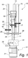
- a device for actuating a rotating shaft selected from a plurality of parallel rotating shafts according to the invention is generally designated with the reference numeral 10.
- Such device 10 comprises among other features :
- the driven gears 17, 18 and 19 are arranged on the respective driven shaft 14, 15 and 16 in an axial position that is offset with respect to the other driven gears.
- the driving gear 13 is capable of performing a translational movement axially with means of translational motion 20 for alternate meshing with one of the driven gears 17, 18, 19.
- the device 10 also comprises means 21, better described hereinbelow, of prevention of rotation for the driven shafts whose driven gear is not meshed with the driving gear 13.
- the driving shaft, with its rotation means, and the three driven shafts are supported by a structure which should be understood as being of known type and is not shown for the sake of simplicity.
- the rotation means 12 for the driving shaft comprise an electric motor with a reduction gearbox 22.
- Such rotation means 12 also comprise a crank 23 for the manual actuation of the device 10 if necessary.
- the means of translational motion 20 for the alternate meshing of the driving gear 13 with one of the driven gears 17, 18, 19 are constituted, by way of non-limiting example of the invention, by an electromechanical actuator of conventional type.
- Such means of translational motion 20 can be actuated by way of an electric motor 24, or alternatively, in the event of no electric power supply, manually by way of a crank 25.
- the driven shafts 14, 15 and 16 are arranged with the same distance between centers with respect to the axis of the driving shaft 11.
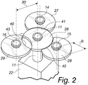
- Such means of prevention of rotation 21 are constituted, for each rotating shaft 11, 14, 15, 16, by a disk-like body, 26, 27, 28, 29 respectively, the three disk-like bodies corresponding to the three driven shafts being fixed coaxially to the corresponding shaft, while the central disk-like body 26 is supported by the driving shaft 11 but is decoupled from it in terms of rotation.
- Each disk-like body has a concave sector, 40, 41, 42, 43 respectively, with a profile shaped like a circular arc; the concavity of the concave sectors 41, 42, 43 of the driven disk-like bodies 27, 28, 29 has a slightly greater radius than the radius R of the central disk-like body 26, while the concavity of the concave sector 40 of the central disk-like body 26 has a contour and dimensions that are such as to allow, thereat, the rotation of each of the driven disk-like bodies 27, 28, 29.
- the driven disk-like bodies 27, 28 and 29 can all be locked alternately by the central disk-like body 26 and each one of them is free to rotate when the concave sector 40 of the central disk-like body 26 is facing toward it.
- the disk-like bodies 26, 27, 28, 29 have the same radius R which is greater than half of the distance between centers 30.
- Each disk-like body has a concave sector, 40, 41, 42 and 43 respectively, with a profile shaped like a circular arc.
- the concavity of such concave sector has a slightly greater radius than the radius R of the disk-like bodies.
- the disk-like bodies are keyed, on the respective rotating shafts, mutually coplanar.
- the central disk-like body 26, which is coaxial with the driving shaft 11, can assume an angular position selected from a number of positions which is equivalent to the number of driven shafts, three in the present embodiment.
- the central disk-like body 26, as in Figure 2 can be rotated and positioned so that its concave sector 40 is facing toward the third disk-like body 29, and in such situation the third disk-like body 29 is free to rotate together with the third driven shaft 16; at the same time the central disk-like body 26 occupies, with corresponding perimetric portions, the concave sectors 41 and 42 respectively of the first disk-like body 27 and of the second disk-like body 28, thus preventing the rotation of these latter two.
- the central disk-like body 26 is able to rotate so as to be arranged with its concave sector 40 facing toward any one of the three disk-like bodies 27, 28 and 29 of the driven shafts 14, 15 and 16, thus alternately freeing the rotation of one driven shaft only with the simultaneous locking of the other two.
- the rotation of the central disk-like body 26 is provided by way of the same electric motor 24 that commands the electromechanical actuator for the driving gear, by way of means of transmission of rotation which are adapted to synchronize the translational motion of the driving gear 13 toward the engagement with one of the driven gears 17, 18 and 19, with the simultaneous rotation of the central disk-like body 26 so as to free the rotation of the disk-like body 27, 28 or 29 corresponding to the driven gear with which the driving gear 13 is to mesh.
- the means of translational motion 20 with the electric motor 24, and the corresponding means 21 of prevention of rotation can be supported by the driving shaft 11.
- a device for actuating a rotating shaft selected from a plurality of parallel rotating shafts which makes it possible to employ a single motor to alternately actuate one of a plurality thereof, thanks to the coordinated actuation of the means of translational motion 20 for the alternate meshing of the driving gear 13 with one of the driven gears 17, 18, 19, and of the means 21 of prevention of rotation for the driven shafts that are not actuated, which determine the simultaneous locking of two driven shafts and the transmission of power to the third driven shaft, which remains free to rotate.
- a device that makes it possible to move a rotating shaft selected from a plurality of rotating shafts, with the shafts that are not made to rotate being kept stably motionless in a precise preset configuration of non-use thanks to the aforesaid means of prevention of rotation, as required by the national and international regulations governing isolating switches.
- a device which is constituted by a lower number of components with respect to similar, conventional driving devices, and at the same time is capable of fully executing the same activities, thus at a lower cost from the viewpoint of its production and from the viewpoint of assembly, and also from the viewpoint of maintenance.
- a device which renders the related civil engineering works less expensive, since the electrical drive units are coaxial and very proximate to each other and can be reached with a single electrical line, and not with three separate electrical lines as with the drives for three shafts with a corresponding number of corresponding drive units, typical of conventional isolating switches.
- a device which can be protected by way of a single containment and protection enclosure, instead of with three separate containment enclosures as with the drives for three shafts with a corresponding number of corresponding drive units of the known type.
- a device is thus devised which is capable of reducing the general costs for the drive unit of an isolating switch and the costs of running such drive unit.
Landscapes
- Engineering & Computer Science (AREA)
- General Engineering & Computer Science (AREA)
- Mechanical Engineering (AREA)
- Transmission Devices (AREA)
- Gear Transmission (AREA)
Claims (6)
- Vorrichtung (10) zur Betätigung einer Drehwelle für die Kontaktelemente eines Trennschalters, wobei die Drehwelle aus einer Vielzahl von parallelen Drehwellen ausgewählt ist, wobei die Vorrichtung umfasst:- eine Antriebswelle (11), die von einem entsprechenden Drehmittel (12) getragen und betätigt wird, das mit einem Antriebsrad (13) zur Übertragung von Drehmoment versehen ist,- eine Vielzahl von angetriebenen Wellen (14, 15, 16), von denen jede mit einem entsprechenden angetriebenen Rad (17, 18, 19) versehen ist, das konfiguriert ist, um mit dem Antriebsrad (13) in Eingriff zu stehen, wobei die angetriebenen Räder (17, 18, 19) auf der jeweiligen angetriebenen Welle in einer axialen Position angeordnet sind, die in Bezug auf die anderen angetriebenen Räder versetzt ist und das Antriebsrad (13) in der Lage ist, eine Translationsbewegung axial mit Mitteln der Translationsbewegung (20) zum abwechselnden Eingriff mit einem der angetriebenen Räder (17, 18, 19) auszuführen,wobei die Vorrichtung (10) weiter Mittel zur Verhinderung der Drehung der angetriebenen Wellen umfasst, deren angetriebenes Rad nicht mit dem Antriebsrad in Eingriff steht, wobei die Mittel aus einer Vielzahl von scheibenartigen Körpern (26, 27, 28, 29) bestehen, die jeweils einen konkaven Sektor (40, 41, 42, 43) mit einem kreisbogenförmigen Profil umfassen, wobei die Vielzahl von scheibenartigen Körpern (26, 27, 28, 29) einen zentralen scheibenartigen Körper (26) einschließen, der von der Antriebswelle (11) getragen wird, aber von diesem hinsichtlich der Drehung entkoppelt ist und jeder der verbleibenden scheibenartigen Körper (27, 28, 29) koaxial zu einer jeweiligen der Vielzahl von angetriebenen Wellen (14, 15, 16) in einer gegenseitig koplanaren Anordnung befestigt ist, wobei die Konkavität der konkaven Sektoren (41, 42, 43) der angetriebenen scheibenförmigen Körper (27, 28, 29) einen geringfügig größeren Radius als der Radius des zentralen scheibenartigen Körpers (26) aufweist und die Konkavität des konkaven Sektors (40) des zentralen scheibenartigen Körpers (26) eine Kontur und Abmessungen aufweist, um dort eine selektive Drehung jedes der angetriebenen scheibenartigen Körper (27, 28, 29) zu ermöglichen.
- Vorrichtung nach Anspruch 1, dadurch gekennzeichnet, dass das Drehmittel (12) für die Antriebswelle einen Elektromotor (21) mit einem Untersetzungsgetriebe (22) und einer Kurbel (23) zur manuellen Betätigung, falls erforderlich, umfasst.
- Vorrichtung nach einem oder mehreren der vorstehenden Ansprüche, dadurch gekennzeichnet, dass das Translationsbewegungsmittel (20) für das abwechselnde Ineinandergreifen des Antriebsrads (13) mit einem der angetriebenen Räder (17, 18, 19) durch einen elektromechanischen Aktuator gebildet ist.
- Vorrichtung nach einem oder mehreren der vorstehenden Ansprüche, dadurch gekennzeichnet, dass das Translationsbewegungsmittel (20) über einen Elektromotor (24) oder manuell über eine Kurbel (25) betätigbar ist.
- Vorrichtung nach einem oder mehreren der vorstehenden Ansprüche, dadurch gekennzeichnet, dass in dem Mittel (21) zur Verhinderung der Drehung für die angetriebenen Wellen, die nicht betätigt sind, die angetriebenen Wellen (14, 15, 16) mit dem gleichen Abstand zwischen den Zentren (30) in Bezug auf die Achse der Antriebswelle (11) angeordnet sind.
- Vorrichtung nach Anspruch 4, dadurch gekennzeichnet, dass die Drehung des zentralen scheibenartigen Körpers (26) mittels des Elektromotors (24) mittels Drehübertragungsmittel erfolgt, die angepasst sind, um die Translationsbewegung des Antriebsrads (13) in Richtung auf den Eingriff mit einem der angetriebenen Räder (17, 18, 19) bei gleichzeitiger Drehung des zentralen scheibenartigen Körpers (26) zu synchronisieren, um so die Drehung des scheibenartigen Körpers (27, 28, 29) freizugeben, die dem angetriebenen Rad entspricht, mit dem das Antriebsrad (13) in Eingriff stehen soll.
Applications Claiming Priority (1)
| Application Number | Priority Date | Filing Date | Title |
|---|---|---|---|
| PCT/EP2014/077045 WO2016091288A1 (en) | 2014-12-09 | 2014-12-09 | Device for actuating a rotating shaft selected from a plurality of parallel rotating shafts |
Publications (2)
| Publication Number | Publication Date |
|---|---|
| EP3230995A1 EP3230995A1 (de) | 2017-10-18 |
| EP3230995B1 true EP3230995B1 (de) | 2018-09-26 |
Family
ID=52101316
Family Applications (1)
| Application Number | Title | Priority Date | Filing Date |
|---|---|---|---|
| EP14812193.2A Active EP3230995B1 (de) | 2014-12-09 | 2014-12-09 | Vorrichtung zur betätigung einer drehwelle aus mehreren parallelen drehwellen |
Country Status (3)
| Country | Link |
|---|---|
| US (1) | US10760684B2 (de) |
| EP (1) | EP3230995B1 (de) |
| WO (1) | WO2016091288A1 (de) |
Cited By (1)
| Publication number | Priority date | Publication date | Assignee | Title |
|---|---|---|---|---|
| EP3486932A1 (de) * | 2017-11-21 | 2019-05-22 | Ormazabal Y Cia S.L.U. | Antriebssystem für elektrische hochspannungsvorrichtungen |
Families Citing this family (2)
| Publication number | Priority date | Publication date | Assignee | Title |
|---|---|---|---|---|
| CN106098430B (zh) * | 2016-08-24 | 2018-01-23 | 天津华宁电子有限公司 | 自动调节联动多点合闸系统 |
| CN113295061A (zh) * | 2021-06-16 | 2021-08-24 | 上海汉未科技有限公司 | 一种弹载电子作动器 |
Family Cites Families (10)
| Publication number | Priority date | Publication date | Assignee | Title |
|---|---|---|---|---|
| DE497122C (de) * | 1930-05-02 | Siemens Schuckertwerke Akt Ges | Trennschalter mit Erdungsschalter mit gemeinsamer Antriebswelle, die durch Laengsverschiebung wechselweise mit dem Trennschalter oder mit dem Erdungsschalter gekuppelt werden kann | |
| GB483439A (en) * | 1936-07-09 | 1938-04-20 | Zd Y Tatra Akciova Spolecnost | Improvements in or relating to the drive for endless track vehicles |
| FR899759A (fr) * | 1943-11-12 | 1945-06-11 | Lefebvre & Martin Ets | Mécanisme de changement de vitesse |
| NL6813678A (de) * | 1968-09-25 | 1970-03-31 | ||
| US4505164A (en) * | 1981-10-08 | 1985-03-19 | Tokuichiro Yoshida | Automatic transmission mechanism with spindle-shaped frictional clutch members incorporated therein |
| US4644113A (en) * | 1985-10-09 | 1987-02-17 | Huang L D | Electric safety device |
| US5235939A (en) * | 1992-11-05 | 1993-08-17 | Ford Motor Company | Automotive engine torsional pulse enhancer |
| DE4319371A1 (de) * | 1993-06-07 | 1994-12-08 | Siemens Ag | Elektrische Schaltanlage |
| US20070140772A1 (en) * | 2005-12-16 | 2007-06-21 | Hewlett-Packard Development Company, L.P. | Torque coupling |
| KR101690129B1 (ko) * | 2012-03-02 | 2017-01-09 | 엘에스산전 주식회사 | 스위치기어용 개폐기 조작장치 |
-
2014
- 2014-12-09 EP EP14812193.2A patent/EP3230995B1/de active Active
- 2014-12-09 US US15/534,843 patent/US10760684B2/en active Active
- 2014-12-09 WO PCT/EP2014/077045 patent/WO2016091288A1/en not_active Ceased
Non-Patent Citations (1)
| Title |
|---|
| None * |
Cited By (1)
| Publication number | Priority date | Publication date | Assignee | Title |
|---|---|---|---|---|
| EP3486932A1 (de) * | 2017-11-21 | 2019-05-22 | Ormazabal Y Cia S.L.U. | Antriebssystem für elektrische hochspannungsvorrichtungen |
Also Published As
| Publication number | Publication date |
|---|---|
| US20170350507A1 (en) | 2017-12-07 |
| US10760684B2 (en) | 2020-09-01 |
| EP3230995A1 (de) | 2017-10-18 |
| WO2016091288A1 (en) | 2016-06-16 |
Similar Documents
| Publication | Publication Date | Title |
|---|---|---|
| EP2359028B1 (de) | Getriebesysteme mit mehreren ausgängen | |
| US10760684B2 (en) | Device for actuating a rotating shaft selected from a plurality of parallel rotating shafts | |
| EP4427953A3 (de) | Elektrisches antriebssystem mit mehrgelenkigem gestänge | |
| RU2012101346A (ru) | Устройство для автоматического управления ручной коробкой передач | |
| HRP20201132T1 (hr) | Selektor za regulacijsku sklopku pod opterećenjem i regulacijska sklopka pod opterećenjem s komutacijskim ormarom i selektorom | |
| RU2014102710A (ru) | Электрически вращательный регулирующий блок, в частности, для непрямых визуальных систем для транспортных средств | |
| KR20130100593A (ko) | 스위치기어용 개폐기 조작장치 | |
| WO2016130778A8 (en) | Grinder | |
| CN110410478B (zh) | 力传递模块 | |
| WO2011107297A3 (de) | Elektromechanischer motor | |
| CN103177901B (zh) | 一种三工位开关操作机构 | |
| EP3098915B1 (de) | Gasisolierte schaltanlage und schalter | |
| WO2018088244A8 (ja) | 直動式電動アクチュエータ | |
| UA119779C2 (uk) | Моторний привід | |
| US9951825B2 (en) | Multi-plate clutch | |
| KR100926719B1 (ko) | 회전 리미트 어셈블리 장치 | |
| CN103177889A (zh) | 一种电气联锁机构 | |
| CN206388616U (zh) | 开关操作机构上的位置切换辅助信号结构 | |
| WO2015104363A3 (de) | Aktorbaugruppe für die gangwahl in einem fahrzeuggetriebe | |
| KR20150003558A (ko) | 가스절연 개폐장치의 접지단로기 | |
| KR20130005577U (ko) | 가스절연개폐장치 | |
| CN103165312A (zh) | 一种联锁机构 | |
| RU2486623C1 (ru) | Привод комбинированного аппарата высокого напряжения | |
| WO2017081913A1 (ja) | 断路器の操作装置 | |
| CN108263431B (zh) | 跨座式单轨道岔 |
Legal Events
| Date | Code | Title | Description |
|---|---|---|---|
| STAA | Information on the status of an ep patent application or granted ep patent |
Free format text: STATUS: THE INTERNATIONAL PUBLICATION HAS BEEN MADE |
|
| PUAI | Public reference made under article 153(3) epc to a published international application that has entered the european phase |
Free format text: ORIGINAL CODE: 0009012 |
|
| STAA | Information on the status of an ep patent application or granted ep patent |
Free format text: STATUS: REQUEST FOR EXAMINATION WAS MADE |
|
| 17P | Request for examination filed |
Effective date: 20170710 |
|
| AK | Designated contracting states |
Kind code of ref document: A1 Designated state(s): AL AT BE BG CH CY CZ DE DK EE ES FI FR GB GR HR HU IE IS IT LI LT LU LV MC MK MT NL NO PL PT RO RS SE SI SK SM TR |
|
| AX | Request for extension of the european patent |
Extension state: BA ME |
|
| DAX | Request for extension of the european patent (deleted) | ||
| GRAP | Despatch of communication of intention to grant a patent |
Free format text: ORIGINAL CODE: EPIDOSNIGR1 |
|
| STAA | Information on the status of an ep patent application or granted ep patent |
Free format text: STATUS: GRANT OF PATENT IS INTENDED |
|
| INTG | Intention to grant announced |
Effective date: 20180629 |
|
| GRAS | Grant fee paid |
Free format text: ORIGINAL CODE: EPIDOSNIGR3 |
|
| GRAA | (expected) grant |
Free format text: ORIGINAL CODE: 0009210 |
|
| STAA | Information on the status of an ep patent application or granted ep patent |
Free format text: STATUS: THE PATENT HAS BEEN GRANTED |
|
| AK | Designated contracting states |
Kind code of ref document: B1 Designated state(s): AL AT BE BG CH CY CZ DE DK EE ES FI FR GB GR HR HU IE IS IT LI LT LU LV MC MK MT NL NO PL PT RO RS SE SI SK SM TR |
|
| REG | Reference to a national code |
Ref country code: GB Ref legal event code: FG4D |
|
| REG | Reference to a national code |
Ref country code: CH Ref legal event code: EP |
|
| REG | Reference to a national code |
Ref country code: AT Ref legal event code: REF Ref document number: 1046998 Country of ref document: AT Kind code of ref document: T Effective date: 20181015 |
|
| REG | Reference to a national code |
Ref country code: IE Ref legal event code: FG4D |
|
| REG | Reference to a national code |
Ref country code: DE Ref legal event code: R096 Ref document number: 602014033106 Country of ref document: DE |
|
| REG | Reference to a national code |
Ref country code: NL Ref legal event code: FP |
|
| PG25 | Lapsed in a contracting state [announced via postgrant information from national office to epo] |
Ref country code: SE Free format text: LAPSE BECAUSE OF FAILURE TO SUBMIT A TRANSLATION OF THE DESCRIPTION OR TO PAY THE FEE WITHIN THE PRESCRIBED TIME-LIMIT Effective date: 20180926 Ref country code: RS Free format text: LAPSE BECAUSE OF FAILURE TO SUBMIT A TRANSLATION OF THE DESCRIPTION OR TO PAY THE FEE WITHIN THE PRESCRIBED TIME-LIMIT Effective date: 20180926 Ref country code: NO Free format text: LAPSE BECAUSE OF FAILURE TO SUBMIT A TRANSLATION OF THE DESCRIPTION OR TO PAY THE FEE WITHIN THE PRESCRIBED TIME-LIMIT Effective date: 20181226 Ref country code: GR Free format text: LAPSE BECAUSE OF FAILURE TO SUBMIT A TRANSLATION OF THE DESCRIPTION OR TO PAY THE FEE WITHIN THE PRESCRIBED TIME-LIMIT Effective date: 20181227 Ref country code: LT Free format text: LAPSE BECAUSE OF FAILURE TO SUBMIT A TRANSLATION OF THE DESCRIPTION OR TO PAY THE FEE WITHIN THE PRESCRIBED TIME-LIMIT Effective date: 20180926 Ref country code: BG Free format text: LAPSE BECAUSE OF FAILURE TO SUBMIT A TRANSLATION OF THE DESCRIPTION OR TO PAY THE FEE WITHIN THE PRESCRIBED TIME-LIMIT Effective date: 20181226 Ref country code: FI Free format text: LAPSE BECAUSE OF FAILURE TO SUBMIT A TRANSLATION OF THE DESCRIPTION OR TO PAY THE FEE WITHIN THE PRESCRIBED TIME-LIMIT Effective date: 20180926 |
|
| REG | Reference to a national code |
Ref country code: LT Ref legal event code: MG4D |
|
| PG25 | Lapsed in a contracting state [announced via postgrant information from national office to epo] |
Ref country code: LV Free format text: LAPSE BECAUSE OF FAILURE TO SUBMIT A TRANSLATION OF THE DESCRIPTION OR TO PAY THE FEE WITHIN THE PRESCRIBED TIME-LIMIT Effective date: 20180926 Ref country code: AL Free format text: LAPSE BECAUSE OF FAILURE TO SUBMIT A TRANSLATION OF THE DESCRIPTION OR TO PAY THE FEE WITHIN THE PRESCRIBED TIME-LIMIT Effective date: 20180926 Ref country code: HR Free format text: LAPSE BECAUSE OF FAILURE TO SUBMIT A TRANSLATION OF THE DESCRIPTION OR TO PAY THE FEE WITHIN THE PRESCRIBED TIME-LIMIT Effective date: 20180926 |
|
| REG | Reference to a national code |
Ref country code: AT Ref legal event code: MK05 Ref document number: 1046998 Country of ref document: AT Kind code of ref document: T Effective date: 20180926 |
|
| PG25 | Lapsed in a contracting state [announced via postgrant information from national office to epo] |
Ref country code: RO Free format text: LAPSE BECAUSE OF FAILURE TO SUBMIT A TRANSLATION OF THE DESCRIPTION OR TO PAY THE FEE WITHIN THE PRESCRIBED TIME-LIMIT Effective date: 20180926 Ref country code: EE Free format text: LAPSE BECAUSE OF FAILURE TO SUBMIT A TRANSLATION OF THE DESCRIPTION OR TO PAY THE FEE WITHIN THE PRESCRIBED TIME-LIMIT Effective date: 20180926 Ref country code: IS Free format text: LAPSE BECAUSE OF FAILURE TO SUBMIT A TRANSLATION OF THE DESCRIPTION OR TO PAY THE FEE WITHIN THE PRESCRIBED TIME-LIMIT Effective date: 20190126 Ref country code: AT Free format text: LAPSE BECAUSE OF FAILURE TO SUBMIT A TRANSLATION OF THE DESCRIPTION OR TO PAY THE FEE WITHIN THE PRESCRIBED TIME-LIMIT Effective date: 20180926 Ref country code: PL Free format text: LAPSE BECAUSE OF FAILURE TO SUBMIT A TRANSLATION OF THE DESCRIPTION OR TO PAY THE FEE WITHIN THE PRESCRIBED TIME-LIMIT Effective date: 20180926 Ref country code: CZ Free format text: LAPSE BECAUSE OF FAILURE TO SUBMIT A TRANSLATION OF THE DESCRIPTION OR TO PAY THE FEE WITHIN THE PRESCRIBED TIME-LIMIT Effective date: 20180926 Ref country code: ES Free format text: LAPSE BECAUSE OF FAILURE TO SUBMIT A TRANSLATION OF THE DESCRIPTION OR TO PAY THE FEE WITHIN THE PRESCRIBED TIME-LIMIT Effective date: 20180926 |
|
| PG25 | Lapsed in a contracting state [announced via postgrant information from national office to epo] |
Ref country code: PT Free format text: LAPSE BECAUSE OF FAILURE TO SUBMIT A TRANSLATION OF THE DESCRIPTION OR TO PAY THE FEE WITHIN THE PRESCRIBED TIME-LIMIT Effective date: 20190126 Ref country code: SM Free format text: LAPSE BECAUSE OF FAILURE TO SUBMIT A TRANSLATION OF THE DESCRIPTION OR TO PAY THE FEE WITHIN THE PRESCRIBED TIME-LIMIT Effective date: 20180926 Ref country code: SK Free format text: LAPSE BECAUSE OF FAILURE TO SUBMIT A TRANSLATION OF THE DESCRIPTION OR TO PAY THE FEE WITHIN THE PRESCRIBED TIME-LIMIT Effective date: 20180926 |
|
| REG | Reference to a national code |
Ref country code: DE Ref legal event code: R097 Ref document number: 602014033106 Country of ref document: DE |
|
| REG | Reference to a national code |
Ref country code: DE Ref legal event code: R119 Ref document number: 602014033106 Country of ref document: DE |
|
| PG25 | Lapsed in a contracting state [announced via postgrant information from national office to epo] |
Ref country code: DK Free format text: LAPSE BECAUSE OF FAILURE TO SUBMIT A TRANSLATION OF THE DESCRIPTION OR TO PAY THE FEE WITHIN THE PRESCRIBED TIME-LIMIT Effective date: 20180926 |
|
| REG | Reference to a national code |
Ref country code: CH Ref legal event code: PL |
|
| PLBE | No opposition filed within time limit |
Free format text: ORIGINAL CODE: 0009261 |
|
| STAA | Information on the status of an ep patent application or granted ep patent |
Free format text: STATUS: NO OPPOSITION FILED WITHIN TIME LIMIT |
|
| GBPC | Gb: european patent ceased through non-payment of renewal fee |
Effective date: 20181226 |
|
| PG25 | Lapsed in a contracting state [announced via postgrant information from national office to epo] |
Ref country code: MC Free format text: LAPSE BECAUSE OF FAILURE TO SUBMIT A TRANSLATION OF THE DESCRIPTION OR TO PAY THE FEE WITHIN THE PRESCRIBED TIME-LIMIT Effective date: 20180926 Ref country code: LU Free format text: LAPSE BECAUSE OF NON-PAYMENT OF DUE FEES Effective date: 20181209 |
|
| 26N | No opposition filed |
Effective date: 20190627 |
|
| REG | Reference to a national code |
Ref country code: IE Ref legal event code: MM4A |
|
| REG | Reference to a national code |
Ref country code: BE Ref legal event code: MM Effective date: 20181231 |
|
| PG25 | Lapsed in a contracting state [announced via postgrant information from national office to epo] |
Ref country code: FR Free format text: LAPSE BECAUSE OF NON-PAYMENT OF DUE FEES Effective date: 20181231 Ref country code: DE Free format text: LAPSE BECAUSE OF NON-PAYMENT OF DUE FEES Effective date: 20190702 Ref country code: IE Free format text: LAPSE BECAUSE OF NON-PAYMENT OF DUE FEES Effective date: 20181209 Ref country code: SI Free format text: LAPSE BECAUSE OF FAILURE TO SUBMIT A TRANSLATION OF THE DESCRIPTION OR TO PAY THE FEE WITHIN THE PRESCRIBED TIME-LIMIT Effective date: 20180926 |
|
| PG25 | Lapsed in a contracting state [announced via postgrant information from national office to epo] |
Ref country code: BE Free format text: LAPSE BECAUSE OF NON-PAYMENT OF DUE FEES Effective date: 20181231 |
|
| PG25 | Lapsed in a contracting state [announced via postgrant information from national office to epo] |
Ref country code: LI Free format text: LAPSE BECAUSE OF NON-PAYMENT OF DUE FEES Effective date: 20181231 Ref country code: CH Free format text: LAPSE BECAUSE OF NON-PAYMENT OF DUE FEES Effective date: 20181231 Ref country code: GB Free format text: LAPSE BECAUSE OF NON-PAYMENT OF DUE FEES Effective date: 20181226 |
|
| PG25 | Lapsed in a contracting state [announced via postgrant information from national office to epo] |
Ref country code: MT Free format text: LAPSE BECAUSE OF NON-PAYMENT OF DUE FEES Effective date: 20181209 |
|
| PG25 | Lapsed in a contracting state [announced via postgrant information from national office to epo] |
Ref country code: TR Free format text: LAPSE BECAUSE OF FAILURE TO SUBMIT A TRANSLATION OF THE DESCRIPTION OR TO PAY THE FEE WITHIN THE PRESCRIBED TIME-LIMIT Effective date: 20180926 |
|
| PG25 | Lapsed in a contracting state [announced via postgrant information from national office to epo] |
Ref country code: CY Free format text: LAPSE BECAUSE OF FAILURE TO SUBMIT A TRANSLATION OF THE DESCRIPTION OR TO PAY THE FEE WITHIN THE PRESCRIBED TIME-LIMIT Effective date: 20180926 Ref country code: HU Free format text: LAPSE BECAUSE OF FAILURE TO SUBMIT A TRANSLATION OF THE DESCRIPTION OR TO PAY THE FEE WITHIN THE PRESCRIBED TIME-LIMIT; INVALID AB INITIO Effective date: 20141209 Ref country code: MK Free format text: LAPSE BECAUSE OF NON-PAYMENT OF DUE FEES Effective date: 20180926 |
|
| P01 | Opt-out of the competence of the unified patent court (upc) registered |
Effective date: 20230522 |
|
| PGFP | Annual fee paid to national office [announced via postgrant information from national office to epo] |
Ref country code: NL Payment date: 20251119 Year of fee payment: 12 |
|
| PGFP | Annual fee paid to national office [announced via postgrant information from national office to epo] |
Ref country code: IT Payment date: 20251119 Year of fee payment: 12 |