EP3231071B1 - Actionneur avec modules statorique et rotorique enrobes - Google Patents
Actionneur avec modules statorique et rotorique enrobes Download PDFInfo
- Publication number
- EP3231071B1 EP3231071B1 EP15813743.0A EP15813743A EP3231071B1 EP 3231071 B1 EP3231071 B1 EP 3231071B1 EP 15813743 A EP15813743 A EP 15813743A EP 3231071 B1 EP3231071 B1 EP 3231071B1
- Authority
- EP
- European Patent Office
- Prior art keywords
- stator
- module
- rotor
- actuator according
- electrical
- Prior art date
- Legal status (The legal status is an assumption and is not a legal conclusion. Google has not performed a legal analysis and makes no representation as to the accuracy of the status listed.)
- Active
Links
Images






Classifications
-
- H—ELECTRICITY
- H02—GENERATION; CONVERSION OR DISTRIBUTION OF ELECTRIC POWER
- H02K—DYNAMO-ELECTRIC MACHINES
- H02K1/00—Details of the magnetic circuit
- H02K1/06—Details of the magnetic circuit characterised by the shape, form or construction
- H02K1/12—Stationary parts of the magnetic circuit
- H02K1/14—Stator cores with salient poles
- H02K1/146—Stator cores with salient poles consisting of a generally annular yoke with salient poles
-
- H—ELECTRICITY
- H02—GENERATION; CONVERSION OR DISTRIBUTION OF ELECTRIC POWER
- H02K—DYNAMO-ELECTRIC MACHINES
- H02K21/00—Synchronous motors having permanent magnets; Synchronous generators having permanent magnets
- H02K21/12—Synchronous motors having permanent magnets; Synchronous generators having permanent magnets with stationary armatures and rotating magnets
- H02K21/14—Synchronous motors having permanent magnets; Synchronous generators having permanent magnets with stationary armatures and rotating magnets with magnets rotating within the armatures
- H02K21/16—Synchronous motors having permanent magnets; Synchronous generators having permanent magnets with stationary armatures and rotating magnets with magnets rotating within the armatures having annular armature cores with salient poles
-
- H—ELECTRICITY
- H02—GENERATION; CONVERSION OR DISTRIBUTION OF ELECTRIC POWER
- H02K—DYNAMO-ELECTRIC MACHINES
- H02K1/00—Details of the magnetic circuit
- H02K1/06—Details of the magnetic circuit characterised by the shape, form or construction
- H02K1/22—Rotating parts of the magnetic circuit
- H02K1/27—Rotor cores with permanent magnets
- H02K1/2706—Inner rotors
-
- H—ELECTRICITY
- H02—GENERATION; CONVERSION OR DISTRIBUTION OF ELECTRIC POWER
- H02K—DYNAMO-ELECTRIC MACHINES
- H02K1/00—Details of the magnetic circuit
- H02K1/06—Details of the magnetic circuit characterised by the shape, form or construction
- H02K1/12—Stationary parts of the magnetic circuit
- H02K1/14—Stator cores with salient poles
- H02K1/146—Stator cores with salient poles consisting of a generally annular yoke with salient poles
- H02K1/148—Sectional cores
-
- H—ELECTRICITY
- H02—GENERATION; CONVERSION OR DISTRIBUTION OF ELECTRIC POWER
- H02K—DYNAMO-ELECTRIC MACHINES
- H02K1/00—Details of the magnetic circuit
- H02K1/06—Details of the magnetic circuit characterised by the shape, form or construction
- H02K1/22—Rotating parts of the magnetic circuit
- H02K1/27—Rotor cores with permanent magnets
- H02K1/2706—Inner rotors
- H02K1/272—Inner rotors the magnetisation axis of the magnets being perpendicular to the rotor axis
- H02K1/274—Inner rotors the magnetisation axis of the magnets being perpendicular to the rotor axis the rotor consisting of two or more circumferentially positioned magnets
- H02K1/2753—Inner rotors the magnetisation axis of the magnets being perpendicular to the rotor axis the rotor consisting of two or more circumferentially positioned magnets the rotor consisting of magnets or groups of magnets arranged with alternating polarity
- H02K1/278—Surface mounted magnets; Inset magnets
-
- H—ELECTRICITY
- H02—GENERATION; CONVERSION OR DISTRIBUTION OF ELECTRIC POWER
- H02K—DYNAMO-ELECTRIC MACHINES
- H02K11/00—Structural association of dynamo-electric machines with electric components or with devices for shielding, monitoring or protection
- H02K11/20—Structural association of dynamo-electric machines with electric components or with devices for shielding, monitoring or protection for measuring, monitoring, testing, protecting or switching
- H02K11/21—Devices for sensing speed or position, or actuated thereby
-
- H—ELECTRICITY
- H02—GENERATION; CONVERSION OR DISTRIBUTION OF ELECTRIC POWER
- H02K—DYNAMO-ELECTRIC MACHINES
- H02K11/00—Structural association of dynamo-electric machines with electric components or with devices for shielding, monitoring or protection
- H02K11/20—Structural association of dynamo-electric machines with electric components or with devices for shielding, monitoring or protection for measuring, monitoring, testing, protecting or switching
- H02K11/21—Devices for sensing speed or position, or actuated thereby
- H02K11/215—Magnetic effect devices, e.g. Hall-effect or magneto-resistive elements
-
- H—ELECTRICITY
- H02—GENERATION; CONVERSION OR DISTRIBUTION OF ELECTRIC POWER
- H02K—DYNAMO-ELECTRIC MACHINES
- H02K11/00—Structural association of dynamo-electric machines with electric components or with devices for shielding, monitoring or protection
- H02K11/30—Structural association with control circuits or drive circuits
-
- H—ELECTRICITY
- H02—GENERATION; CONVERSION OR DISTRIBUTION OF ELECTRIC POWER
- H02K—DYNAMO-ELECTRIC MACHINES
- H02K11/00—Structural association of dynamo-electric machines with electric components or with devices for shielding, monitoring or protection
- H02K11/30—Structural association with control circuits or drive circuits
- H02K11/33—Drive circuits, e.g. power electronics
-
- H—ELECTRICITY
- H02—GENERATION; CONVERSION OR DISTRIBUTION OF ELECTRIC POWER
- H02K—DYNAMO-ELECTRIC MACHINES
- H02K15/00—Processes or apparatus specially adapted for manufacturing, assembling, maintaining or repairing of dynamo-electric machines
- H02K15/02—Processes or apparatus specially adapted for manufacturing, assembling, maintaining or repairing of dynamo-electric machines of stator or rotor bodies
- H02K15/03—Processes or apparatus specially adapted for manufacturing, assembling, maintaining or repairing of dynamo-electric machines of stator or rotor bodies having permanent magnets
-
- H—ELECTRICITY
- H02—GENERATION; CONVERSION OR DISTRIBUTION OF ELECTRIC POWER
- H02K—DYNAMO-ELECTRIC MACHINES
- H02K21/00—Synchronous motors having permanent magnets; Synchronous generators having permanent magnets
- H02K21/12—Synchronous motors having permanent magnets; Synchronous generators having permanent magnets with stationary armatures and rotating magnets
- H02K21/24—Synchronous motors having permanent magnets; Synchronous generators having permanent magnets with stationary armatures and rotating magnets with magnets axially facing the armatures, e.g. hub-type cycle dynamos
-
- H—ELECTRICITY
- H02—GENERATION; CONVERSION OR DISTRIBUTION OF ELECTRIC POWER
- H02K—DYNAMO-ELECTRIC MACHINES
- H02K29/00—Motors or generators having non-mechanical commutating devices, e.g. discharge tubes or semiconductor devices
-
- H—ELECTRICITY
- H02—GENERATION; CONVERSION OR DISTRIBUTION OF ELECTRIC POWER
- H02K—DYNAMO-ELECTRIC MACHINES
- H02K29/00—Motors or generators having non-mechanical commutating devices, e.g. discharge tubes or semiconductor devices
- H02K29/06—Motors or generators having non-mechanical commutating devices, e.g. discharge tubes or semiconductor devices with position sensing devices
- H02K29/08—Motors or generators having non-mechanical commutating devices, e.g. discharge tubes or semiconductor devices with position sensing devices using magnetic effect devices, e.g. Hall-plates, magneto-resistors
-
- H—ELECTRICITY
- H02—GENERATION; CONVERSION OR DISTRIBUTION OF ELECTRIC POWER
- H02K—DYNAMO-ELECTRIC MACHINES
- H02K3/00—Details of windings
- H02K3/32—Windings characterised by the shape, form or construction of the insulation
- H02K3/325—Windings characterised by the shape, form or construction of the insulation for windings on salient poles, such as claw-shaped poles
-
- H—ELECTRICITY
- H02—GENERATION; CONVERSION OR DISTRIBUTION OF ELECTRIC POWER
- H02K—DYNAMO-ELECTRIC MACHINES
- H02K3/00—Details of windings
- H02K3/46—Fastening of windings on the stator or rotor structure
- H02K3/52—Fastening salient pole windings or connections thereto
- H02K3/521—Fastening salient pole windings or connections thereto applicable to stators only
- H02K3/522—Fastening salient pole windings or connections thereto applicable to stators only for generally annular cores with salient poles
-
- H—ELECTRICITY
- H02—GENERATION; CONVERSION OR DISTRIBUTION OF ELECTRIC POWER
- H02K—DYNAMO-ELECTRIC MACHINES
- H02K37/00—Motors with rotor rotating step by step and without interrupter or commutator driven by the rotor, e.g. stepping motors
- H02K37/10—Motors with rotor rotating step by step and without interrupter or commutator driven by the rotor, e.g. stepping motors of permanent magnet type
- H02K37/12—Motors with rotor rotating step by step and without interrupter or commutator driven by the rotor, e.g. stepping motors of permanent magnet type with stationary armatures and rotating magnets
- H02K37/14—Motors with rotor rotating step by step and without interrupter or commutator driven by the rotor, e.g. stepping motors of permanent magnet type with stationary armatures and rotating magnets with magnets rotating within the armatures
-
- H—ELECTRICITY
- H02—GENERATION; CONVERSION OR DISTRIBUTION OF ELECTRIC POWER
- H02K—DYNAMO-ELECTRIC MACHINES
- H02K5/00—Casings; Enclosures; Supports
- H02K5/04—Casings or enclosures characterised by the shape, form or construction thereof
- H02K5/08—Insulating casings
-
- H—ELECTRICITY
- H02—GENERATION; CONVERSION OR DISTRIBUTION OF ELECTRIC POWER
- H02K—DYNAMO-ELECTRIC MACHINES
- H02K5/00—Casings; Enclosures; Supports
- H02K5/04—Casings or enclosures characterised by the shape, form or construction thereof
- H02K5/16—Means for supporting bearings, e.g. insulating supports or means for fitting bearings in the bearing-shields
- H02K5/173—Means for supporting bearings, e.g. insulating supports or means for fitting bearings in the bearing-shields using bearings with rolling contact, e.g. ball bearings
- H02K5/1732—Means for supporting bearings, e.g. insulating supports or means for fitting bearings in the bearing-shields using bearings with rolling contact, e.g. ball bearings radially supporting the rotary shaft at both ends of the rotor
-
- H—ELECTRICITY
- H02—GENERATION; CONVERSION OR DISTRIBUTION OF ELECTRIC POWER
- H02K—DYNAMO-ELECTRIC MACHINES
- H02K5/00—Casings; Enclosures; Supports
- H02K5/04—Casings or enclosures characterised by the shape, form or construction thereof
- H02K5/22—Auxiliary parts of casings not covered by groups H02K5/06-H02K5/20, e.g. shaped to form connection boxes or terminal boxes
- H02K5/225—Terminal boxes or connection arrangements
-
- H—ELECTRICITY
- H02—GENERATION; CONVERSION OR DISTRIBUTION OF ELECTRIC POWER
- H02K—DYNAMO-ELECTRIC MACHINES
- H02K2203/00—Specific aspects not provided for in the other groups of this subclass relating to the windings
- H02K2203/03—Machines characterised by the wiring boards, i.e. printed circuit boards or similar structures for connecting the winding terminations
-
- H—ELECTRICITY
- H02—GENERATION; CONVERSION OR DISTRIBUTION OF ELECTRIC POWER
- H02K—DYNAMO-ELECTRIC MACHINES
- H02K2203/00—Specific aspects not provided for in the other groups of this subclass relating to the windings
- H02K2203/09—Machines characterised by wiring elements other than wires, e.g. bus rings, for connecting the winding terminations
-
- H—ELECTRICITY
- H02—GENERATION; CONVERSION OR DISTRIBUTION OF ELECTRIC POWER
- H02K—DYNAMO-ELECTRIC MACHINES
- H02K2203/00—Specific aspects not provided for in the other groups of this subclass relating to the windings
- H02K2203/12—Machines characterised by the bobbins for supporting the windings
-
- H—ELECTRICITY
- H02—GENERATION; CONVERSION OR DISTRIBUTION OF ELECTRIC POWER
- H02K—DYNAMO-ELECTRIC MACHINES
- H02K2213/00—Specific aspects, not otherwise provided for and not covered by codes H02K2201/00 - H02K2211/00
- H02K2213/12—Machines characterised by the modularity of some components
Definitions
- the present invention relates to the field of brushless type polyphase electric motors having a series of permanent magnets interacting with a soft ferromagnetic stator supporting electric coils.
- the coils are powered by a polyphase alternating current through electronic switching provided by an electronic circuit.
- the invention more particularly proposes an actuator formed of a motor and electronic assembly integrated in a compact and simple manner in separate coated modules (for example by overmolding a plastic, polymer or even metallic material) then assembled.
- the Hall probes, as well as the electronic circuit controlling them, and the electrical connection assembly for the motor phases must be assembled into an integral product that can be placed and used in any application (for example for move different valves, flaps or shafts in an internal combustion engine).
- Patent applications EP2781758 , US2010/301691 , WO2011159674 Or US2008/023028 describe other examples of embodiment of the prior art.
- the present invention aims to remedy these drawbacks by proposing a device comprising a coated stator module, insertable into the housing of a motor or an actuator to interact electromagnetically with a rotor and cooperating with a rotor module.
- the invention relates in its most general sense to an electric actuator as defined in claim 1, as well as a method of manufacturing a magnetized rotor module according to claim 13.
- the motor is thus made up of two complementary components that do not require an electrical connection or assembly parts.
- the connection is ensured by the complementary configuration of the two coated components, each presenting a complementary assembly interface indexed to guarantee the precise relative positioning of these two components.
- a main advantage of the invention and its modular realization is a significant reduction in the number of parts necessary for the production of the actuator when compared to the achievements of the prior art.
- stator module also includes an electronic circuit also coated to form a second “intelligent” component.
- the actuator comprises a second electrical connection assembly managing the power supply and the signals of the detection elements necessary for switching the different phases of the motor and the stator module coats the first and second electrical connection assembly .
- This second assembly is thus necessary when one wishes to control the motor using an encoder assembly integrated into the motor. It is not necessary if you wish to control the motor in self-commutated “sensorless” mode.
- the stator assembly has a cavity capable of receiving said rotor module.
- the first and second electrical connection assemblies form a radial coated extension of said stator module.
- first and second electrical connection assemblies form an axial coated extension of said stator module.
- the flange has an external shape complementary to the receiving zone of the stator module to allow easy assembly.
- Said flange of the rotor module has centering lugs capable of engaging in complementary housings formed on the stator module.
- the stator module comprises a set of superimposed sheets having a plurality of teeth, at least part of which supports an electric coil, each of said electric coils having connection lugs extending axially, said stator module comprising in addition to a connection assembly formed of connection tabs for the connection of a complementary connector, all of the components comprising said set of wound sheets, said coil connection tabs and said connection tabs for the connection of a connector are coated in an insulating plastic material to form a monolithic block encompassing the exterior surfaces of said superimposed sheets.
- the interior surface of said teeth of the stator sheets can be made flush with the interior surface of said monolithic block and the cavity made cylindrical and closed at its rear part by a molded bottom.
- said molded bottom may include a ring for guiding the axis of rotation of the rotor.
- the interior surface of said teeth of the stator sheets is included in said monolithic block, the thickness of the coating plastic material being less than the air gap between the exterior cylindrical surface of the rotor and the cylindrical envelope defined by the surface stator teeth.
- the invention also relates to a magnetized rotor module formed by a coated sleeve comprising a bearing for guiding the rotor, the sleeve being surrounded by a collar capable of being fixed to a stator structure by welding or screwing or riveting.
- the cavity opens out and the actuator has a third module comprising a printed circuit and closing the actuator on the rear part.
- the invention described relates to a rotary motor formed by assembling a rotor module and a stator module.
- the constituents of these modules are mechanically linked to be permanently secured.
- the rotor module is finally assembled.
- the stator module is coated in an insulating plastic material leaving only the electrical connection elements protruding.
- These two modules are assembled by inserting the rotor module into a housing provided for this purpose in the stator module, and joined by screwing, welding or gluing.
- a third module can possibly close the actuator when the stator module has a cavity opening.
- an actuator according to the invention commonly comprises a motor having a stator (1) having teeth extending radially, provided with electric coils (2) carried by coil bodies (3) as visible in figure 1 .
- the motor is three-phase and as described in the application EP2002531 , but the invention is in no way limited to this particular technology.
- a first connection assembly (6) is positioned on a front face of the stator (1) to ensure the electrical connection of the coils (2).
- the second connection assembly (7) intended to manage (power supply and output signal) the detection elements (typically Hall effect probes) necessary for the operation of the brushless motor following the lessons of the state of the art on the subject, on an exterior surface of the first connection assembly (6) as shown in figure 2 .
- the indexing of the first connection assembly (6) on the stator (1) is ensured thanks to guide cavities (4) made in the coil bodies (3) allowing precise positioning.
- the electrical connection is ensured by the insertion, in the notches (5) of the coil body (3), of the terminations of the first connection assembly (6), for example by displacement of the insulator (IDC for Insulation Displacement contact in English).
- the tracks (6a, 6b, 6c) extend radially then laterally relative to the stator, and are in the form of tracks with rectangular section.
- the tracks end in forked connection tabs (not shown) allowing an electrical phase to be connected by IDC contact.
- This assembly is produced by cutting and folding a metal sheet, for example bronze or a copper alloy of the CuZn30 type, then overmolded with an insulating resin (8) as shown in figure 2 .
- the second connection assembly (7) represented in figure 2 allows the connection of a set of signals - for example those of Hall probes - belonging to an encoder used to detect the position of the rotor of said motor from a printed circuit to this same connector.
- five tracks (7a to 7e) are used to supply and operate the signals from the Hall probes.
- This second assembly (7) is then positioned on the first coated assembly as shown in figure 2 .
- stator (1) associated with the first (6) and second (7) connection assembly, is described more precisely in the application FR 12/59035 .
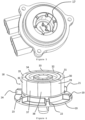
- stator (1) as well as the first (6) and second (7) connection assembly are coated together in an injection mold to form a monolithic and closed part shown in Figure 3 .
- the coated assembly then constitutes the stator module (9).
- this stator module (9) may vary depending on the final applications. In the example of figures 1 to 6 , this is a first so-called “discal” embodiment in the sense that the actuator produced has a larger dimension depending on its diameter than depending on its height.
- the coating here produced by overmolding covers all of the constituents of the stator, with the exception of the ends of the different tracks (7a to 7e and 6a to 6c), which protrude, inside two openings (10 and 11) to allow an electrical connection to an external socket or to an external auxiliary electronic circuit.
- stator module (9) Inside this stator module (9), the teeth of the stator (1) are either flush with the overmolding, or covered with a thin skin during overmolding.
- This monolithic part forming the stator module (9) has an annular cavity (12) whose bottom is closed in this first embodiment of the Figure 4 .
- the stator module (9) has three lateral protuberances (13 to 15) pierced to allow the fixing of the actuator.
- the overmolded stator module (9) is thus completely waterproof and autonomous.
- the bottom of the cavity (12) allows the tabs (16a to 16e) of the second connection assembly (7), the interior ends of the tracks (7a to 7e), to protrude. These tabs (16a to 16e) ensure the connection with an electronic circuit (17) of disc shape, which can be housed at the bottom of the cavity (12) as shown in Figure 5 .
- the stator module (9) allows, by its shape, to receive a rotor module (18) presented in figures 6 And 7 .
- the rotor module (18) comprises a flange (19) having centering lugs (20 to 24) extending radially and also having a mechanical rigidity function.
- the flange (19) forms, on the inside of the rotor module (18), a ring (25) receiving a guide element (28) guiding the axis (26) of the magnetic rotor (27).
- the magnetic rotor (27) is constituted by an alternation of permanent magnets (29 to 38) of alternating polarities (North / South).
- FIG. 7 presents a sectional view of the rotor module (18) making it possible to better appreciate the relative positioning of the flange (19) and the bearing (25) guiding the axis (26).
- This encoder magnet (40) is used to detect the position of the rotor in collaboration with the detection elements and the electronic circuit (17) in the bottom of the cavity (12) not opening out from the stator module (9), facing this encoder magnet (40) when the stator (9) and rotor (18) modules are assembled.
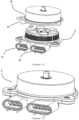
- FIG 8 represents the installation of the rotor module (18) in the stator module (9), by insertion according to an axial displacement (relative to the axis of rotation of the actuator - the displacement is visualized by the thick arrow), indexing of the two modules thanks to the lugs (20 to 24) which are housed in complementary housings (44 to 49), then assembled by screwing, gluing, ultrasonic welding or any other known assembly method.
- FIG. 9 represents a view of the two assembled modules then forming the actuator (39) in its finalized version.
- THE figures 10 , 11 And 12 represent a second embodiment of the actuator (39) in a so-called “tubular” shape, that is to say an actuator whose height dimension is greater than that of its diameter.
- the actuator (39) drives a screw (42).
- the stator module (9) locally has an electrical connection socket (43) extending radially relative to the axis of rotation of the actuator (39).
- the rotor module (18) comprises a flange (19) receiving, as in the first embodiment, a housing to receive a guide element (28).
- FIG. 11 represents a sectional view of the stator of this other alternative embodiment.
- the rotor module (18) has an interior core formed by a stack of disc sheets (50) forcibly engaged on an axis (26) and supporting permanent magnets (29 to 38) in the form of tiles.
- the stator (1) is powered via a connection assembly described in the European patent EP2212985 of the plaintiff.
- the stator (1) receives a second connection assembly (7) for positioning a Hall probe.
- This assembly is overmolded to form a monolithic part, with a main body (51) and a secondary body (52) whose longitudinal axis is perpendicular to that of the main body (51).
- the rotor module (18) is indexed, by complementarity of the shapes of the modules, inside the stator module (9).
- THE figures 13 and 14 show a third embodiment where the rotor module (18) is attached to the stator module (9) from the outside.
- the flange (19) of the rotor module (18) is in fact here of a diameter greater than that of the stator (1) of the stator module (9).
- the invention is not limited to a motor having a stator with radial teeth. It also applies to an engine whose stator has teeth extending parallel to the axis, with a disc rotor, or even a linear motor.
- This embodiment differs from the mode described in Figure 10 in that the rotor module (18) comprises a second guide element (28') which is made integral with the axis (26) after assembly of the pack of sheets (50). This achievement makes it possible to mount two guide elements (28 and 28') of smaller size and allows easier assembly in the stator module (9).
- a sensor magnet (53) is then assembled with its support on the free end of the axis (by driving or screwing for example).
- This axle assembly + sheet metal package + motor magnets + bearing rear + sensor magnet on its support is finally assembled, after magnetization of the motor magnets and the sensor in place, on the overmolded module formed of the rear guide element (28) and the flange (19).
- the stator module (9) particularly has an opening interior cavity (12) which allows the formed rotor module (18) to be assembled more easily and to attach a third module (56) closing the actuator on the rear part.
- FIG. 19 presents an alternative embodiment of an actuator (39) according to the invention where the stator module (9) accommodates an on-board electronic circuit allowing the management of motor control.
- the stator module (9) accommodates an on-board electronic circuit allowing the management of motor control.
- the typical elements that can be found in this electronic circuit are: a switching logic management module (60), one or more filtering capacitors (61), a set of MosFet type switching transistors (62). to control the power supply of the different phases.
- These electronic elements are then positioned on the module molded stator (9) and a cover (not shown) can be placed glued, welded, screwed or riveted to complete the motor.
Landscapes
- Engineering & Computer Science (AREA)
- Power Engineering (AREA)
- Microelectronics & Electronic Packaging (AREA)
- Manufacturing & Machinery (AREA)
- Iron Core Of Rotating Electric Machines (AREA)
- Manufacture Of Motors, Generators (AREA)
- Brushless Motors (AREA)
- Motor Or Generator Frames (AREA)
- Insulation, Fastening Of Motor, Generator Windings (AREA)
- Permanent Magnet Type Synchronous Machine (AREA)
Description
- La présente invention concerne le domaine des moteurs électriques polyphasés de type sans balais présentant une série d'aimants permanents interagissant avec un stator ferromagnétique doux supportant des bobines électriques. Les bobines sont alimentées par un courant alternatif polyphasé au travers d'une commutation électronique fournie par un circuit électronique.
- L'invention propose plus particulièrement un actionneur formé d'un ensemble moteur et électronique intégrés de manière compacte et simple dans des modules séparés enrobés (par exemple par surmoulage d'une matière plastique, polymère ou même métallique) puis assemblés.
- On entend, dans la suite de ce texte, par « moteur » l'ensemble des éléments (bobine, stator ferromagnétique doux, aimants permanents et culasse ferromagnétique douce éventuelle) du circuit magnétique permettant de réaliser l'effort magnétique et par « actionneur » l'ensemble du moteur, dans sa version finalisée, associé aux éléments d'alimentation électrique du moteur et de détection de position.
- On connait, dans l'état de la technique, nombre de moteurs électriques polyphasés sans balai à aimants permanents comme par exemple ceux décrits dans le brevet
EP0949747 ou la demandeEP2002531 , tous deux de la demanderesse. Les moteurs de ce type sont composés d'un ensemble stator bobiné et d'un ensemble rotor comprenant une pluralité d'aimants. Afin d'assurer la commutation électrique des différentes phases de ces moteurs, la solution généralement choisie consiste à utiliser au moins une sonde de Hall placée en regard de la pluralité d'aimants ou d'un ensemble aimanté auxiliaire dédié à cette commutation. - Afin de réaliser un actionneur, les sondes de Hall, ainsi que le circuit électronique les pilotant, et l'ensemble de connexion électrique des phases du moteur doivent être assemblés dans un produit intégral pouvant être placé et utilisé dans une application quelconque (par exemple pour déplacer différentes vannes, volets ou arbres dans un moteur à combustion interne).
- Dans les solutions de l'art antérieur, il existe diverses réalisations. Par exemple, certaines solutions consistent à surmouler partiellement le moteur, le plus souvent seul le stator étant surmoulé. La demande de brevet
PCT WO/2009/055625 se rapporte à un ensemble stator et à un procédé de réalisation d'un ensemble stator. L'ensemble stator est surmoulé d'une composition polymère thermiquement conductrice et électriquement isolante. Le noyau de stator de l'ensemble stator est recouvert d'un composant adhésif afin de permettre un meilleur transfert de chaleur à l'interface du noyau de stator et des bobines surmoulées. - On connaît aussi la demande de brevet
EP1677404 décrit un moteur pour une direction assistée électrique, dans lequel la connexion de la bobine peut être facilement réalisé avec un gain de place, et un procédé de fabrication du moteur. Des bobines de stator sont assemblés en un noyau de stator et reliées par phase par des anneaux de liaison. - Les demandes de brevet
EP2781758 ,US2010/301691 ,WO2011159674 ouUS2008/023028 décrivent d'autres exemples de réalisation de l'art antérieur. - Inconvénients des solutions de l'art antérieur
- Les solutions de l'art antérieur présentent l'inconvénient d'un assemblage compliqué, nécessitant un positionnement mécanique précis des pièces statoriques dans le boîtier et/ou par rapport au rotor. Lors de l'assemblage, il est nécessaire de réaliser de multiples liaisons mécaniques et électriques afin d'assurer le raccordement des bobines à un faisceau de câblage ou des éléments de connexion avec le circuit électronique, les connecteurs électriques et le cas échéant avec un circuit imprimé. Ces différentes opérations nécessitent une grande précision et sont sources de fragilité du dispositif.
- Les solutions de surmoulage connues dans l'art antérieur ne permettent pas d'assurer l'enrobage de l'intégralité des composants d'une structure stator et ne permettent que partiellement d'éviter le problème de l'assemblage et des connexions électriques.
- En particulier, dans la solution proposée dans la demande de brevet
EP1677404 , le stator bobiné et la connectique ne forment pas une ensemble encapsulé, ce qui conduit à des faiblesses mécaniques. - La présente invention vise à remédier à ces inconvénients en proposant un dispositif comprenant un module statorique enrobé, insérable dans le boîtier d'un moteur ou d'un actionneur pour interagir de manière électromagnétique avec un rotor et coopérant avec un module rotorique.
- L'invention concerne selon son acception la plus générale un actionneur électrique tel que défini dans la revendication 1, ainsi qu'un procédé de fabrication d'un module rotorique aimanté conforme à la revendication 13.
- Le module rotorique forme ainsi un premier composant intégrant :
- le rotor constitué d'une culasse sur laquelle sont montés les aimants permanents et l'axe de sortie,
- un élément de guidage
- une flasque assurant l'enrobage de cet ensemble.
- Le module statorique forme un deuxième composant intégrant :
- le stator bobiné
- un premier ensemble de connexion électrique
- ces éléments étant également enrobés.
- Le moteur est ainsi constitué de deux composants complémentaires ne nécessitant pas de liaison électrique, ni de pièces d'assemblages. La liaison est assurée par la configuration complémentaire des deux composants enrobés, présentant chacun une interface d'assemblage complémentaire indexée pour garantir le positionnement relatif précis de ces deux composants.
- Un avantage important de cette réalisation modulaire enrobée est une meilleure gestion de la température des ensembles de connexion électrique et du circuit imprimé les reliant. En effet, lorsque l'actionneur travaille à haute température, la chaleur est confinée au niveau du stator, qui supporte aisément cette charge thermique, et n'est que faiblement diffusée à l'arrière de l'actionneur vers les éléments de connexion électriques et électroniques. Il est ainsi possible de limiter l'échauffement du circuit imprimé de façon importante par rapport aux réalisations de l'art antérieur.
- Un avantage principal de l'invention et sa réalisation modulaire est une réduction importante du nombre de pièces nécessaires à la réalisation de l'actionneur lorsque comparé aux réalisations de l'art antérieur.
- Optionnellement, le module statorique comprend en plus un circuit électronique également enrobé pour former un second composant « intelligent ».
- De manière préférée mais non limitative, l'actionneur comprend un deuxième ensemble de connexion électrique gérant l'alimentation et les signaux des éléments de détection nécessaire à la commutation des différentes phases du moteur et le module statorique enrobe le premier et deuxième ensemble de connexion électrique. Ce deuxième ensemble est ainsi nécessaire lorsque l'on souhaite piloter le moteur grâce à un ensemble codeur intégré au moteur. Il n'est pas nécessaire si l'on souhait piloter le moteur en mode « sans capteur » auto-commuté (sensorless).
- L'ensemble statorique présente une cavité apte à recevoir ledit module rotorique.
- Dans un mode de réalisation les premier et deuxième ensembles de connexion électrique forment un prolongement enrobé radial dudit module statorique.
- Dans un autre mode de réalisation les premier et deuxième ensembles de connexion électrique forment un prolongement enrobé axial dudit module statorique.
- Préférentiellement, le flasque présente une forme extérieure complémentaire de la zone de réception du module statorique pour permettre un assemblage aisé.
- Ledit flasque du module rotorique présente des ergots de centrage aptes à s'engager dans des logements complémentaires formés sur le module statorique.
- Dans un mode particulier de réalisation, le module statorique comprend un ensemble de tôles superposées présentant une pluralité de dents dont une partie au moins supporte une bobine électrique, chacune desdites bobines électriques présentant des pattes de connexion s'étendant axialement, ledit module statorique comportant en outre un ensemble de connexion formé de pattes de connexion pour le raccordement d'un connecteur complémentaire, la totalité des composants comprenant ledit ensemble de tôles bobiné, lesdites pattes de connexion des bobines et lesdites pattes de connexion pour le raccordement d'un connecteur sont enrobées dans une matière plastique isolante pour former un bloc monolithique englobant les surfaces extérieures desdites tôles superposées.
- La surface intérieure desdites dents des tôles statoriques peut être rendue affleurant par rapport à la surface intérieure dudit bloc monolithique et la cavité rendue cylindrique et fermée à sa partie arrière par un fond moulé. Dans ce cas, ledit fond moulé peut comprendre une bague pour le guidage de l'axe de rotation du rotor.
- Selon une variante, la surface intérieure desdites dents des tôles statoriques est incluse dans ledit bloc monolithique, l'épaisseur de la matière plastique enrobant étant inférieure à l'entrefer compris entre la surface cylindrique extérieure du rotor et l'enveloppe cylindrique définie par la surface des dents statoriques.
- L'invention concerne aussi un module rotorique aimanté formé par une douille enrobée comprenant un roulement pour le guidage du rotor, la douille étant entourée par une collerette apte à être fixée sur une structure statorique par soudage ou vissage ou rivetage.
- Dans une variante de réalisation, la cavité est débouchant et l'actionneur présente un troisième module comportant un circuit imprimé et fermant l'actionneur sur la partie arrière.
- L'invention concerne aussi un procédé de fabrication d'un module rotorique aimanté caractérisé en ce qu'il comporte les étapes suivantes :
- Surmoulage du roulement avant pour former le flasque avec ses ergots de positionnement et d'indexation,
- Assemblage d'un paquet de tôles sur l'axe du rotor,
- Collage du ou des aimants du moteur sur le paquet de tôles,
- Assemblage du roulement arrière sur l'axe comportant le paquet de tôles.
- L'invention sera mieux comprise à la lecture de la description qui suit, se référant aux dessins annexés correspondant à des exemples non limitatifs de réalisation, où :
- les
figures 1 et2 représentent le module statorique bobiné avec les moyens de connexion électrique du moteur et de l'ensemble de détection, - la
figure 3 représente le module statorique enrobé, - les
figures 4 et5 représentent des vues de la cavité formée dans le stator enrobé respectivement avant et après l'insertion du circuit électronique, - les
figures 6 et7 représentent des vues du module rotorique respectivement en vue de trois-quarts et en coupe longitudinale, - les
figures 8 et9 représentent des vues de l'assemblage du stator enrobé et du module rotorique respectivement avant assemblage et après assemblage, dans un premier mode de réalisation dit mode « discal », - les
figures 10 à 12 représentent des vues de l'assemblage du stator enrobé et du module rotorique respectivement avant assemblage (figure 10 ), en vue de coupe (figure 11 ) et après assemblage (figure 12 ), dans un second mode de réalisation dit mode « tubulaire », - les
figures 13 et 14 représentent des vues, respectivement avant assemblage des modules et après assemblage des modules, dans un troisième mode de réalisation où le module rotorique vient autour du module statorique, - la
figure 15 représente une vue en coupe des modes décrits enfigures 13 et 14 , - les
figures 16 et17 représentent des vues en coupe, respectivement du module rotorique et du module statorique, d'un mode de réalisation tubulaire alternatif, - la
figure 18 une vue en coupe du moteur assemblé à partir des modules décrits enfigures 16 et17 - la
figure 19 représente une variante de réalisation de l'invention. - L'invention décrite concerne un moteur rotatif formé par assemblage d'un module rotorique et d'un module statorique. Les constituants de ces modules sont liés mécaniquement pour être définitivement solidarisés.
- Le module rotorique est définitivement assemblé. De même, le module statorique est enrobé dans une matière plastique isolant ne laissant dépasser que les éléments de connexion électrique. Ces deux modules sont assemblés par une insertion du module rotorique dans un logement prévu à cet effet dans le module statorique, et réunis par vissage, soudure ou collage. Un troisième module peut éventuellement venir fermer l'actionneur lorsque le module statorique présente une cavité débouchant.
- Dans un premier mode de réalisation, un actionneur selon l'invention comprend communément un moteur ayant un stator (1) présentant des dents s'étendant radialement, munies de bobines électriques (2) portées par des corps de bobine (3) comme visibles en
figure 1 . - Dans cet exemple décrit, le moteur est triphasé et tel que décrit dans la demande
EP2002531 , mais l'invention n'est nullement limitée à cette technologie particulière. - Un premier ensemble de connexion (6) se positionne sur une face frontale du stator (1) pour assurer la connexion électrique des bobines (2). On positionne ensuite le deuxième ensemble de connexion (7), destiné à gérer (alimentation et signal de sortie) les éléments de détection (typiquement des sondes à effet Hall) nécessaires au fonctionnement du moteur sans balai suivant les enseignements de l'état de l'art en la matière, sur une surface extérieure du premier ensemble de connexion (6) comme représenté en
figure 2 . - L'indexation du premier ensemble de connexion (6) sur le stator (1) est assurée grâce à des cavités de guidage (4) réalisées dans les corps de bobine (3) permettant un positionnement précis. La connexion électrique est assurée par l'insertion, dans les encoches (5) du corps de bobine (3), des terminaisons du premier ensemble de connexion (6), par exemple par déplacement de l'isolant (IDC pour Insulation Displacement contact en anglais).
- Dans cet exemple, il existe trois phases électriques qui sont alimentées par 3 pistes distinctes (6a, 6b, 6c). Les pistes (6a, 6b, 6c) s'étendent radialement puis latéralement par rapport au stator, et se présentent sous la forme de pistes à section rectangulaire.
- Les pistes se terminent par des pattes de raccordement fourchues (non montrées) permettant de connecter une phase électrique par contact IDC.
- Cet ensemble est réalisé par découpage et pliage d'une feuille métallique, par exemple du bronze ou d'un alliage de cuivre de type CuZn30, puis surmoulée avec une résine isolante (8) comme représenté en
figure 2 . - Le deuxième ensemble de connexion (7) représenté en
figure 2 permet la connexion d'un ensemble de signaux -par exemple ceux de sondes de Hall- appartenant à un codeur servant à détecter la position du rotor dudit moteur depuis un circuit imprimé vers ce même connecteur. Ici, cinq pistes (7a à 7e) sont utilisées pour permettre l'alimentation et l'exploitation des signaux des sondes de Hall. Ce deuxième ensemble (7) est ensuite positionné sur le premier ensemble enrobé comme représenté enfigure 2 . - Ce mode de réalisation du stator (1), associé aux premiers (6) et deuxième (7) ensemble de connexion, est décrit plus précisément dans la demande
FR 12/59035 - Le stator (1) ainsi que les premiers (6) et deuxième (7) ensemble de connexion sont enrobés ensemble dans un moule d'injection pour former une pièce monolithique et fermée représentée en
figure 3 . L'ensemble enrobé constitue alors le module statorique (9). - La forme de ce module statorique (9) peut varier en fonction des applications finales. Dans l'exemple des
figures 1 à 6 , il s'agit d'un premier mode de réalisation dit « discal » dans le sens où l'actionneur réalisé présente une dimension plus importante suivant son diamètre que suivant sa hauteur. - L'enrobage ici réalisée par surmoulage recouvre l'intégralité des constituants du stator, à l'exception des extrémités des différentes pistes (7a à 7e et 6a à 6c), qui dépassent, à l'intérieur de deux ouvertures (10 et 11) pour permettre une connexion électrique à une prise extérieur ou à un circuit électronique annexe extérieur.
- A l'intérieur de ce module statorique (9), les dents du stator (1) sont soit affleurant au surmoulage, soit recouvertes d'une peau mince lors du surmoulage. Cette pièce monolithique formant le module statorique (9) présente une cavité annulaire (12) dont le fond est fermé dans ce premier mode de réalisation de la
figure 4 . Le module statorique (9) présente trois protubérances latérales (13 à 15) percées pour permettre la fixation de l'actionneur. Le module statorique (9) surmoulé est ainsi totalement étanche et autonome. - Le fond de la cavité (12) laisse dépasser les pattes (16a à 16e) du deuxième ensemble de connexion (7), extrémités intérieures des pistes (7a à 7e). Ces pattes (16a à 16e) assurent la liaison avec un circuit électronique (17) de forme discal, pouvant être logé au fond de la cavité (12) comme représenté en
figure 5 . - Le module statorique (9) permet, par sa forme, de recevoir un module rotorique (18) présenté en
figures 6 et7 . - Le module rotorique (18) comprend un flasque (19) présentant des ergots de centrage (20 à 24) s'étendant radialement et ayant aussi une fonction de rigidité mécanique. Le flasque (19) forme, sur l'intérieur du module rotorique (18), une bague (25) recevant un élément de guidage (28) guidant l'axe (26) du rotor magnétique (27).
- Le rotor magnétique (27) est constitué par une alternance d'aimants permanents (29 à 38) de polarités (Nord / Sud) alternées.
- La
figure 7 présente une vue en coupe du module rotorique (18) permettant de mieux apprécier le positionnement relatif du flasque (19) et du roulement (25) de guidage de l'axe (26). On y voit la culasse ferromagnétique (41) sur laquelle sont positionnés les aimants (29 à 38) et l'aimant codeur (40) constitué d'une alternance de polarités aimantées. Cet aimant codeur (40) sert à la détection de position du rotor en collaboration avec les éléments de détection et le circuit électronique (17) dans le fond de la cavité (12) non débouchant du module statorique (9), en regard de cet aimant codeur (40) lorsque les modules statorique (9) et rotorique (18) sont assemblés. - La
figure 8 représente la mise en place du module rotorique (18) dans le module statorique (9), par insertion selon un déplacement axial (relativement à l'axe de rotation de l'actionneur - le déplacement est visualisé par la flèche épaisse), indexation des deux modules grâce aux ergots (20 à 24) qui viennent se loger dans des logements complémentaires (44 à 49), puis assemblage par vissage, collage, soudure ultrason ou tout autre mode d'assemblage connu. - La
figure 9 représente une vue des deux modules assemblés formant alors l'actionneur (39) dans sa version finalisée. - Les
figures 10 ,11 et12 représentent un deuxième mode de réalisation de l'actionneur (39) suivant une forme dite « tubulaire », c'est-à-dire un actionneur dont la dimension de hauteur est supérieure à celle de son diamètre. - Dans cette variante, l'actionneur (39) entraîne une vis (42). Dans cet exemple, le module statorique (9) présente localement une prise de connexion (43) électrique s'étendant radialement par rapport à l'axe de rotation de l'actionneur (39).
- Le module rotorique (18) comprend un flasque (19) recevant, de même que pour le premier mode de réalisation, un logement pour recevoir un élément de guidage (28).
- La
figure 11 représente une vue en coupe du stator de cette autre variante de réalisation. Le module rotorique (18) présente un cœur intérieur formé par un empilement de tôles discales (50) engagées de force sur un axe (26) et supportant des aimants permanents (29 à 38) en forme de tuiles. - Le stator (1) est alimenté par l'intermédiaire d'un ensemble de connexion décrit dans le brevet européen
EP2212985 de la demanderesse. Le stator (1) reçoit un deuxième ensemble de connexion (7) pour le positionnement d'une sonde de Hall. - Cet ensemble est surmoulé pour former une pièce monolithique, avec un corps principal (51) et un corps secondaire (52) dont l'axe longitudinal est perpendiculaire à celui du corps principal (51).
- Dans les modes de réalisation montrées précédemment, le module rotorique (18) vient s'indexer, par complémentarité des formes des modules, à l'intérieur du module statorique (9).
- Les
figures 13 et 14 montrent un troisième mode de réalisation où le module rotorique (18) vient se fixer au module statorique (9) par l'extérieur. - Le flasque (19) du module rotorique (18) est en effet ici d'un diamètre supérieur à celui du stator (1) du module statorique (9).
- La
figure 15 permet d'apprécier le détail des éléments que l'on retrouve dans ce mode de réalisation. Les différents éléments pointés étant identiques dans leur fonction à ceux cités dans les modes précédents. - L'invention n'est pas limitée à un moteur présentant un stator à dents radiales. Elle s'applique aussi à un moteur dont le stator présente des dents s'étendant parallèlement à l'axe, avec un rotor discal, ou encore un moteur linéaire.
- La variante de réalisation des
figures 10 ,11 et12 permet de réaliser une version dite « tubulaire » décrite précédemment. - Il est possible d'envisager une alternative de réalisation afin d'obtenir un ensemble plus compact. Cette alternative est particulièrement décrite en
figures 16 à 18 . - Ce mode de réalisation diffère du mode décrit en
figure 10 en ce que le module rotorique (18) comprend un deuxième un élément de guidage (28') qui est rendu solidaire de l'axe (26) après le montage du paquet de tôles (50). Cette réalisation permet de monter deux éléments de guidage (28 et 28') de plus petite taille et permet un assemblage plus aisé dans le module statorique (9). - Le module rotorique (18) est typiquement réalisé avec les étapes suivantes :
- on surmoule l'élément de guidage avant (28) pour former le flasque avec ses ergots (20) de positionnement et d'indexation,
- on assemble le paquet de tôles (50) sur l'axe (26) du rotor,
- on colle le ou les aimants (29) du moteur sur le paquet de tôles (50),
- on assemble l'élément de guidage arrière (28') sur l'axe (26) comportant le paquet de tôles (50).
- Dans l'exemple décrit on assemble ensuite un aimant capteur (53) avec son support sur l'extrémité libre de l'axe (par chassage ou vissage par exemple).
- Cet ensemble axe + paquet de tôles + aimants moteur + roulement arrière + aimant capteur sur son support est enfin assemblé, après aimantation des aimants du moteur et du capteur en place, sur le module surmoulé formé de l'élément de guidage arrière (28) et du flasque (19).
- Le module statorique (9) présente particulièrement une cavité intérieure (12) débouchant qui permet un assemblage du module rotorique (18) formé plus aisé et de venir rapporter un troisième module (56) fermant l'actionneur sur la partie arrière.
- Après l'assemblage des deux modules statorique (9) et rotorique (18), il reste en effet à ajouter un module électronique complémentaire comprenant, dans cet exemple, le circuit imprimé (17) recevant le ou les sondes de détection (55) du champ magnétique capteur et un capot de fermeture (54). Cette réalisation permet avantageusement de permettre l'intégration d'un circuit imprimé de taille plus importante (que celui présenté en mode de réalisation des
figures 10 et11 ) pour éventuellement pouvoir placer aussi un circuit électronique de pilotage embarqué pilotant directement les phases du moteur. - La
figure 19 présente un mode de réalisation alternatif d'un actionneur (39) selon l'invention où le module statorique (9) accueille un circuit électronique embarqué permettant la gestion du pilotage du moteur. On parle alors d'un moteur « intelligent » ou « smart » et la connectique sortant du moteur est simplifiée car il n'y a pas à sortir hors du moteur les pattes électriques du deuxième ensemble de connexion (7). Les éléments typiques que l'on peut trouver dans ce circuit électronique sont : un module de gestion (60) de la logique de commutation, une ou plusieurs capacités de filtrage (61), un ensemble de transistors (62) de commutation de type MosFet pour commander l'alimentation des différentes phases. Ces éléments électroniques sont alors positionnés sur le module statorique surmoulé (9) et un couvercle (non montré) peut être placé collé, soudé, vissé ou riveté pour terminer le moteur.
Claims (15)
- - Actionneur électrique formé d'un moteur sans balais polyphasé comportant un rotor (27) muni d'aimants permanents (29 à 38) et solidaire d'un axe de sortie (26), et un stator (1) portant des bobines (2) et assurant l'entraînement magnétique du rotor (27), un premier ensemble de connexion électrique (6) alimentant les bobines (2), ledit stator (1) étant intégré dans un module statorique (9) formé d'une matière enrobant le stator (1) bobiné ainsi que le premier (6) ensemble de connexion électrique, caractérisé en ce que ledit rotor (27) est intégré dans un module rotorique (18) constitué par un flasque (19) enrobant un roulement de guidage (28) assurant le guidage de l'axe (26) du rotor (27) et en ce que les modules statorique (9) et rotorique (18) présentent des éléments d'indexation et de fixation l'un par rapport à l'autre, ledit flasque (19) avec ses ergots de positionnement et d'indexation présentant des ergots de centrages (20, 21, 22, 23, 24) qui s'étendent radialement et qui sont aptes à s'engager dans des logements complémentaires (44, 45, 46, 47, 48, 49) formés sur le module statorique (18), ledit flasque (19) formant, sur l'intérieur du module rotorique (18), une bague (25) recevant le roulement de guidage (28), le moteur est constitué de deux composants complémentaires :- Le module rotorique (18) formant un premier composant intégrant le rotor (27), ledit roulement de guidage (28) et le flasque (19) assurant l'enrobage de ce roulement de guidage (28) ;- Le module statorique (9) formant un deuxième composant intégrant le stator (1) et le premier ensemble de connexion électrique (6) enrobés ensemble,- Le module rotorique (18) est mis en place dans le module statorique (9) par insertion selon un déplacement axial, relativement à l'axe de rotation de l'actionneur.
- - Actionneur selon la revendication 1 caractérisé en ce qu'il comprend un deuxième (7) ensemble de connexion électrique gérant l'alimentation et les signaux des éléments de détection nécessaires à la commutation des différentes phases du moteur et en ce que le module statorique (9) enrobe le premier (6) et deuxième (7) ensemble de connexion électrique.
- - Actionneur électrique selon la revendication 2 caractérisé en ce que les premier (6) et deuxième (7) ensembles de connexion électrique forment un prolongement enrobé radial dudit module statorique (9).
- - Actionneur électrique selon la revendication 2 caractérisé en ce que les premier (6) et deuxième (7) ensembles de connexion électrique forment un prolongement enrobé axial dudit module statorique (9).
- - Actionneur électrique selon l'une quelconque des revendications précédentes caractérisé en ce que ledit flasque (19) présente une forme extérieure complémentaire de la zone d'indexation du module statorique (9).
- - Actionneur électrique selon l'une quelconque des revendications précédentes caractérisé en ce que ledit module statorique (9) comprend un ensemble de tôles superposées (50) présentant une pluralité de dents dont une partie au moins supporte une bobine électrique, chacune desdites bobines électriques présentant des pattes de connexion s'étendant axialement, ledit module statorique (9) comportant en outre un ensemble de connexion (7) formé de pattes de connexion pour le raccordement d'un connecteur complémentaire, la totalité des composants comprenant ledit ensemble de tôles bobiné, lesdites pattes de connexion des bobines et lesdites pattes de connexion pour le raccordement d'un connecteur sont enrobées dans une matière plastique isolante pour former un bloc monolithique englobant les surfaces extérieures desdites tôles superposées (50).
- - Actionneur électrique selon la revendication précédente caractérisé en ce que la surface intérieure desdites dents des tôles statoriques est affleurant par rapport à la surface intérieure dudit bloc monolithique.
- - Actionneur électrique selon la revendication 1 caractérisé en ce qu'une cavité (12) apte à recevoir ledit module rotorique (18) est cylindrique est fermée à sa partie arrière par un fond moulé.
- - Actionneur électrique selon la revendication précédente caractérisé en ce que ledit fond moulé comprend une bague pour le guidage de l'axe (26) de rotation du rotor (27).
- - Actionneur électrique selon la revendication 6 caractérisé en ce que la surface intérieure desdites dents des tôles statoriques est incluse dans ledit bloc monolithique, l'épaisseur de la matière plastique enrobant étant inférieure à l'entrefer compris entre la surface cylindrique extérieure du rotor et l'enveloppe cylindrique définie par la surface des dents statoriques.
- - Actionneur électrique selon la revendication 1 caractérisé en ce que ladite cavité (12) est débouchant.
- - Actionneur électrique selon la revendication précédente caractérisé en ce que qu'il présente un troisième module comportant un circuit électronique (17) et en ce que le troisième module ferme l'actionneur sur la partie arrière.
- - Procédé de fabrication d'un actionneur électrique conforme à la revendication 1 avec un module rotorique aimanté (18) constitué par un flasque (19) enrobant un roulement de guidage (28) assurant le guidage de l'axe (26) du rotor (27), caractérisé en ce qu'il comporte les étapes suivantes :- Surmoulage d'un roulement de guidage avant (28) pour former le flasque avec ses ergots (20) de positionnement et d'indexation,- Assemblage d'un paquet de tôles (50) sur l'axe (26) du rotor (27),- Collage du ou des aimants (29) du moteur sur le paquet de tôles (50),- Assemblage du roulement de guidage arrière (28') sur l'axe (26) comportant le paquet de tôles (50).
- - Actionneur électrique selon la revendication 1 caractérisé en ce que l'actionneur est intelligent, le module statorique (9) enrobé accueillant un circuit électronique (17) destiné à piloter l'actionneur et présentant des transistors de commutation et un circuit de commande logique de ces transistors de commutation.
- - Actionneur électrique selon la revendication précédente caractérisé en ce qu'un couvercle (54) vient enfermer ce circuit électronique (17) placé sur ledit module statorique (9).
Applications Claiming Priority (2)
| Application Number | Priority Date | Filing Date | Title |
|---|---|---|---|
| FR1462289A FR3030147B1 (fr) | 2014-12-11 | 2014-12-11 | Actionneur avec modules statorique et rotorique enrobes |
| PCT/EP2015/079302 WO2016092035A1 (fr) | 2014-12-11 | 2015-12-10 | Actionneur avec modules statorique et rotorique enrobes |
Publications (2)
| Publication Number | Publication Date |
|---|---|
| EP3231071A1 EP3231071A1 (fr) | 2017-10-18 |
| EP3231071B1 true EP3231071B1 (fr) | 2024-04-03 |
Family
ID=53059189
Family Applications (1)
| Application Number | Title | Priority Date | Filing Date |
|---|---|---|---|
| EP15813743.0A Active EP3231071B1 (fr) | 2014-12-11 | 2015-12-10 | Actionneur avec modules statorique et rotorique enrobes |
Country Status (6)
| Country | Link |
|---|---|
| US (1) | US10594173B2 (fr) |
| EP (1) | EP3231071B1 (fr) |
| JP (1) | JP6768660B2 (fr) |
| CN (1) | CN107112832B (fr) |
| FR (1) | FR3030147B1 (fr) |
| WO (1) | WO2016092035A1 (fr) |
Families Citing this family (14)
| Publication number | Priority date | Publication date | Assignee | Title |
|---|---|---|---|---|
| FR3042639B1 (fr) | 2015-10-20 | 2017-12-08 | Moving Magnet Tech | Actionneur lineaire a stabilite magnetique et force d'arrachement ameliorees |
| FR3045239B1 (fr) * | 2015-12-15 | 2018-01-19 | Moving Magnet Technologies | Actionneur a cadre mobile bobine et dynamique amelioree |
| FR3052821B1 (fr) * | 2016-06-20 | 2018-06-22 | Sonceboz Automotive Sa | Pompe a fluide motorisee a rechauffement ameliore |
| FR3060892B1 (fr) * | 2016-12-21 | 2021-01-22 | Mmt ag | Actionneur mecatronique |
| FR3064835B1 (fr) | 2017-03-31 | 2020-01-17 | Moving Magnet Technologies | Stator pour machine electrique |
| FR3064837B1 (fr) | 2017-04-03 | 2020-01-17 | Moving Magnet Technologies | Rotor pour machine electrique a aimants permanents internes |
| FR3080234B1 (fr) | 2018-04-13 | 2021-09-24 | Mmt ag | Actionneur electrique compact lineaire et a chaine cinematique elastique |
| FR3086814B1 (fr) * | 2018-09-28 | 2020-10-30 | Sonceboz Mechatronics Boncourt Sa | Actionneur electrique |
| EP3637592B1 (fr) * | 2018-10-10 | 2021-04-28 | Vitesco Technologies GmbH | Stator de moteur électrique |
| DE102019206197A1 (de) * | 2019-04-30 | 2020-11-05 | Mahle International Gmbh | Expansionsventil |
| DE102020215268A1 (de) | 2020-12-03 | 2022-06-09 | Mahle International Gmbh | Expansionsventil |
| CN113941858B (zh) * | 2021-09-27 | 2023-02-03 | 华为技术有限公司 | 记忆合金马达组装装置 |
| CN116707175A (zh) * | 2022-02-25 | 2023-09-05 | 建准电机工业股份有限公司 | 具有多个定子模块的马达及其定子 |
| US11942829B2 (en) * | 2022-07-26 | 2024-03-26 | Borgwarner Inc. | Bonded rotor plate |
Citations (15)
| Publication number | Priority date | Publication date | Assignee | Title |
|---|---|---|---|---|
| US5583419A (en) * | 1994-06-18 | 1996-12-10 | Smiths Industries Public Limited Company | Power supply systems |
| US6314009B1 (en) * | 1998-02-13 | 2001-11-06 | Robert Bosch Gmbh | Device and method for controlled parallel operation of direct current converters |
| US20040061380A1 (en) * | 2002-09-26 | 2004-04-01 | Hann Raymond E. | Power management system for variable load applications |
| US20050274556A1 (en) * | 2000-07-06 | 2005-12-15 | Chaney George T | Hybrid electric vehicle chassis with removable battery module |
| US20080150356A1 (en) * | 2006-12-20 | 2008-06-26 | The Boeing Company | Vehicular Power Distribution System And Method |
| US7468561B2 (en) * | 2007-03-27 | 2008-12-23 | General Electric Company | Integrated electrical power extraction for aircraft engines |
| FR2931801A1 (fr) * | 2008-05-30 | 2009-12-04 | Airbus | Systeme et procede d'alimentation d'une charge electrique d'un aeronef |
| EP2164148A2 (fr) * | 2008-09-16 | 2010-03-17 | Honeywell International Inc. | Procédé et système pour améliorer la capacité de puissance de pic d'un réseau électrique (p.ex. d'un avion) |
| US20100071371A1 (en) * | 2007-03-20 | 2010-03-25 | Airbus Operations Gmbh | Power regulating device for an aircraft |
| US20100102625A1 (en) * | 2008-10-24 | 2010-04-29 | The Boeing Company | Intelligent Energy Management Architecture |
| US20120065790A1 (en) * | 2010-09-15 | 2012-03-15 | Boy Ralph W | Electrical load management system |
| US20120091789A1 (en) * | 2010-10-15 | 2012-04-19 | Eads Construcciones Aeronauticas, S.A. | Electrical power control system for a vehicle |
| US20120232728A1 (en) * | 2011-03-10 | 2012-09-13 | Karimi Kamiar J | Vehicle Electrical Power Management and Distribution |
| US20130062943A1 (en) * | 2011-09-14 | 2013-03-14 | Hamilton Sundstrand Corporation | Load shedding circuit for ram air turbines |
| WO2014106712A1 (fr) * | 2013-01-03 | 2014-07-10 | Microturbo | Procede de gestion du reseau d'alimentation electrique d'un aeronef |
Family Cites Families (25)
| Publication number | Priority date | Publication date | Assignee | Title |
|---|---|---|---|---|
| FR1259035A (fr) | 1960-03-11 | 1961-04-21 | Elveco Ets | Dispositif de fixation des stators de condensateurs variables et des connexions rigides de divers organes des appareils à très haute fréquence |
| JP3147495B2 (ja) * | 1992-06-16 | 2001-03-19 | 松下電器産業株式会社 | 樹脂モールド型電動機 |
| JP2563103Y2 (ja) * | 1992-10-07 | 1998-02-18 | 松下電器産業株式会社 | モールドモータのロータ部位置決め装置 |
| FR2754953B1 (fr) | 1996-10-21 | 1999-02-26 | Moving Magnet Tech | Moteur polyphase, notamment pour l'entrainement d'une aiguille d'un afficheur |
| FR2781758B1 (fr) * | 1998-07-29 | 2000-09-15 | Hema Technologies | Dispositif de distribution, notamment pour doseur de machine de remplissage, et doseur equipe d'un tel dispositif |
| AU2001241958A1 (en) | 2000-03-03 | 2001-09-17 | Valentis, Inc. | Improved poloxamer and poloxamine compositions for nucleic acid delivery |
| JP3760820B2 (ja) * | 2000-11-14 | 2006-03-29 | トヨタ自動車株式会社 | 自動車およびその電力系統制御装置 |
| JP4903324B2 (ja) * | 2001-06-18 | 2012-03-28 | ソニー株式会社 | ヘッドアクチュエータおよび磁気記録再生装置 |
| JP4430501B2 (ja) * | 2004-09-29 | 2010-03-10 | トヨタ自動車株式会社 | 動力出力装置およびそれを備えた車両 |
| JP4783012B2 (ja) * | 2004-12-28 | 2011-09-28 | 日立オートモティブシステムズ株式会社 | 電動パワーステアリング用モータ及びその製造方法 |
| JP2007097257A (ja) * | 2005-09-27 | 2007-04-12 | Nidec Sankyo Corp | キャンドモータ及びキャンドポンプ |
| FR2899396B1 (fr) | 2006-03-30 | 2008-07-04 | Moving Magnet Tech Mmt | Moteur electrique polyphase notamment pour l'entrainement de pompes ou de ventilateurs |
| JP4700570B2 (ja) | 2006-07-14 | 2011-06-15 | 株式会社新川 | ボンディング装置並びにボンディングツール先端部の洗浄方法及びプログラム |
| US20080024028A1 (en) * | 2006-07-27 | 2008-01-31 | Islam Mohammad S | Permanent magnet electric motor |
| US7939975B2 (en) | 2007-10-26 | 2011-05-10 | E. I Du Pont De Nemours And Company | Over-mold stator assembly and process for preparation thereof |
| FR2923951B1 (fr) | 2007-11-19 | 2009-11-27 | Sonceboz Automotive Sa | Ensemble de connexion electrique pour moteur sans balai. |
| US7907062B2 (en) * | 2008-01-31 | 2011-03-15 | Hitachi Global Sotrage Technologies Netherlands B.V. | Dual direction power and data transfer protocol and safety detection |
| JP2009284658A (ja) * | 2008-05-22 | 2009-12-03 | Asmo Co Ltd | ロータ及びモータ |
| JP4906807B2 (ja) * | 2008-07-30 | 2012-03-28 | 三菱電機株式会社 | 電動機の固定子及び電動機及び空気調和機 |
| JP5430480B2 (ja) * | 2009-09-25 | 2014-02-26 | 株式会社ヴァレオジャパン | 駆動モータ |
| JP5476040B2 (ja) * | 2009-05-13 | 2014-04-23 | カヤバ工業株式会社 | モータ |
| US8680727B2 (en) * | 2009-05-27 | 2014-03-25 | Cts Corporation | Brushless direct current actuator with clip for retaining bobbins |
| EP2580850B1 (fr) * | 2010-06-14 | 2021-11-10 | Black & Decker, Inc. | Unité de commande pour moteur sans balais dans un outil électrique |
| WO2013072948A1 (fr) * | 2011-11-14 | 2013-05-23 | 三菱電機株式会社 | Pompe, dispositif de cycle de réfrigération, et procédé de fabrication de pompe |
| FR2996072B1 (fr) * | 2012-09-26 | 2016-07-29 | Sonceboz Automotive Sa | Ensemble de connexion electrique pour moteur sans balai |
-
2014
- 2014-12-11 FR FR1462289A patent/FR3030147B1/fr active Active
-
2015
- 2015-12-10 WO PCT/EP2015/079302 patent/WO2016092035A1/fr not_active Ceased
- 2015-12-10 CN CN201580073064.7A patent/CN107112832B/zh active Active
- 2015-12-10 EP EP15813743.0A patent/EP3231071B1/fr active Active
- 2015-12-10 US US15/534,885 patent/US10594173B2/en active Active
- 2015-12-10 JP JP2017531490A patent/JP6768660B2/ja active Active
Patent Citations (15)
| Publication number | Priority date | Publication date | Assignee | Title |
|---|---|---|---|---|
| US5583419A (en) * | 1994-06-18 | 1996-12-10 | Smiths Industries Public Limited Company | Power supply systems |
| US6314009B1 (en) * | 1998-02-13 | 2001-11-06 | Robert Bosch Gmbh | Device and method for controlled parallel operation of direct current converters |
| US20050274556A1 (en) * | 2000-07-06 | 2005-12-15 | Chaney George T | Hybrid electric vehicle chassis with removable battery module |
| US20040061380A1 (en) * | 2002-09-26 | 2004-04-01 | Hann Raymond E. | Power management system for variable load applications |
| US20080150356A1 (en) * | 2006-12-20 | 2008-06-26 | The Boeing Company | Vehicular Power Distribution System And Method |
| US20100071371A1 (en) * | 2007-03-20 | 2010-03-25 | Airbus Operations Gmbh | Power regulating device for an aircraft |
| US7468561B2 (en) * | 2007-03-27 | 2008-12-23 | General Electric Company | Integrated electrical power extraction for aircraft engines |
| FR2931801A1 (fr) * | 2008-05-30 | 2009-12-04 | Airbus | Systeme et procede d'alimentation d'une charge electrique d'un aeronef |
| EP2164148A2 (fr) * | 2008-09-16 | 2010-03-17 | Honeywell International Inc. | Procédé et système pour améliorer la capacité de puissance de pic d'un réseau électrique (p.ex. d'un avion) |
| US20100102625A1 (en) * | 2008-10-24 | 2010-04-29 | The Boeing Company | Intelligent Energy Management Architecture |
| US20120065790A1 (en) * | 2010-09-15 | 2012-03-15 | Boy Ralph W | Electrical load management system |
| US20120091789A1 (en) * | 2010-10-15 | 2012-04-19 | Eads Construcciones Aeronauticas, S.A. | Electrical power control system for a vehicle |
| US20120232728A1 (en) * | 2011-03-10 | 2012-09-13 | Karimi Kamiar J | Vehicle Electrical Power Management and Distribution |
| US20130062943A1 (en) * | 2011-09-14 | 2013-03-14 | Hamilton Sundstrand Corporation | Load shedding circuit for ram air turbines |
| WO2014106712A1 (fr) * | 2013-01-03 | 2014-07-10 | Microturbo | Procede de gestion du reseau d'alimentation electrique d'un aeronef |
Also Published As
| Publication number | Publication date |
|---|---|
| US20170324284A1 (en) | 2017-11-09 |
| CN107112832B (zh) | 2021-02-12 |
| EP3231071A1 (fr) | 2017-10-18 |
| FR3030147A1 (fr) | 2016-06-17 |
| US10594173B2 (en) | 2020-03-17 |
| CN107112832A (zh) | 2017-08-29 |
| JP6768660B2 (ja) | 2020-10-14 |
| FR3030147B1 (fr) | 2018-03-16 |
| JP2017538391A (ja) | 2017-12-21 |
| WO2016092035A1 (fr) | 2016-06-16 |
Similar Documents
| Publication | Publication Date | Title |
|---|---|---|
| EP3231071B1 (fr) | Actionneur avec modules statorique et rotorique enrobes | |
| EP3857685B1 (fr) | Actionneur électrique | |
| EP3254360B1 (fr) | Actionneur de positionnement et procede de fabrication | |
| FR2930380A1 (fr) | Dispositif formant moteur electrique pour direction assistee et dispositif de direction assistee | |
| WO2024022675A1 (fr) | Machine électrique à flux axial | |
| WO2019105975A1 (fr) | Connecteur de phase electrique pour stator de machine electrique tournante | |
| WO2020260715A1 (fr) | Palier plastique pour machine électrique tournante | |
| EP3322612B1 (fr) | Machine électrique tournante pour véhicule automobile | |
| EP4073908A1 (fr) | Moteur electrique comprenant un boitier avec un surmoulage de stator et ensembles de connexion | |
| FR3011402A1 (fr) | Moteur electrique comportant un stator segmente | |
| EP3472468B1 (fr) | Pompe a fluide motorisée a réchauffement amélioré | |
| EP4169149A1 (fr) | Ensemble comprenant une machine électrique tournante, un connecteur et un module électronique | |
| JP2019216549A (ja) | コイル、モータステータ、モータ、および電動アクチュエータ | |
| EP3769405B1 (fr) | Dispositif de connexion electrique pour machine electrique tournante | |
| EP3226387A1 (fr) | Porte-balais pour machine électrique tournante muni d'un porte-capteur de température intégré | |
| EP4122082B1 (fr) | Ensemble comprenant une machine electrique tournante, un module electronique et un connecteur | |
| EP2225819A2 (fr) | Agencement d'un porte-cible sur un ventilateur de machine electrique tournante | |
| FR3054937A1 (fr) | Demarreur muni d'un porte balais comprenant un ressort | |
| WO2025026671A1 (fr) | Collecteur électrique tournant d'un rotor bobiné et ensemble rotor le comprenant | |
| WO2024110396A1 (fr) | Machine électrique tournante polyphasée à flux électromagnétique axial | |
| WO2021123547A1 (fr) | Moteur pour dispositif de ventilation d'une installation de chauffage, ventilation et/ou climatisation de vehicule automobile a rotor et stator decouples d'une embase de montage | |
| FR3107148A1 (fr) | Ensemble d’un stator de moteur électrique de dispositif de ventilation de véhicule automobile et d’une carte électronique de commande du moteur | |
| FR3048828A1 (fr) | Machine electrique tournante munie d'un capteur de mesure de champ magnetique pour la mesure d'un courant | |
| FR3050881A1 (fr) | Dispositif porte-balais pour demarreur | |
| FR3057119A1 (fr) | Machine electrique tournante munie d'un connecteur de commande modulable |
Legal Events
| Date | Code | Title | Description |
|---|---|---|---|
| STAA | Information on the status of an ep patent application or granted ep patent |
Free format text: STATUS: THE INTERNATIONAL PUBLICATION HAS BEEN MADE |
|
| PUAI | Public reference made under article 153(3) epc to a published international application that has entered the european phase |
Free format text: ORIGINAL CODE: 0009012 |
|
| STAA | Information on the status of an ep patent application or granted ep patent |
Free format text: STATUS: REQUEST FOR EXAMINATION WAS MADE |
|
| 17P | Request for examination filed |
Effective date: 20170609 |
|
| AK | Designated contracting states |
Kind code of ref document: A1 Designated state(s): AL AT BE BG CH CY CZ DE DK EE ES FI FR GB GR HR HU IE IS IT LI LT LU LV MC MK MT NL NO PL PT RO RS SE SI SK SM TR |
|
| AX | Request for extension of the european patent |
Extension state: BA ME |
|
| DAV | Request for validation of the european patent (deleted) | ||
| DAX | Request for extension of the european patent (deleted) | ||
| STAA | Information on the status of an ep patent application or granted ep patent |
Free format text: STATUS: EXAMINATION IS IN PROGRESS |
|
| 17Q | First examination report despatched |
Effective date: 20181217 |
|
| REG | Reference to a national code |
Ref country code: DE Ref legal event code: R079 Free format text: PREVIOUS MAIN CLASS: H02K0021160000 Ipc: H02K0001278000 Ref country code: DE Ref legal event code: R079 Ref document number: 602015088174 Country of ref document: DE Free format text: PREVIOUS MAIN CLASS: H02K0021160000 Ipc: H02K0001278000 |
|
| RIC1 | Information provided on ipc code assigned before grant |
Ipc: H02K 5/22 20060101ALI20230428BHEP Ipc: H02K 5/173 20060101ALI20230428BHEP Ipc: H02K 5/08 20060101ALI20230428BHEP Ipc: H02K 3/52 20060101ALI20230428BHEP Ipc: H02K 3/32 20060101ALI20230428BHEP Ipc: H02K 1/14 20060101ALI20230428BHEP Ipc: H02K 37/14 20060101ALI20230428BHEP Ipc: H02K 29/08 20060101ALI20230428BHEP Ipc: H02K 11/33 20160101ALI20230428BHEP Ipc: H02K 21/24 20060101ALI20230428BHEP Ipc: H02K 21/16 20060101ALI20230428BHEP Ipc: H02K 11/215 20160101ALI20230428BHEP Ipc: H02K 1/278 20220101AFI20230428BHEP |
|
| GRAJ | Information related to disapproval of communication of intention to grant by the applicant or resumption of examination proceedings by the epo deleted |
Free format text: ORIGINAL CODE: EPIDOSDIGR1 |
|
| STAA | Information on the status of an ep patent application or granted ep patent |
Free format text: STATUS: GRANT OF PATENT IS INTENDED |
|
| GRAP | Despatch of communication of intention to grant a patent |
Free format text: ORIGINAL CODE: EPIDOSNIGR1 |
|
| INTG | Intention to grant announced |
Effective date: 20231026 |
|
| GRAS | Grant fee paid |
Free format text: ORIGINAL CODE: EPIDOSNIGR3 |
|
| GRAA | (expected) grant |
Free format text: ORIGINAL CODE: 0009210 |
|
| STAA | Information on the status of an ep patent application or granted ep patent |
Free format text: STATUS: THE PATENT HAS BEEN GRANTED |
|
| AK | Designated contracting states |
Kind code of ref document: B1 Designated state(s): AL AT BE BG CH CY CZ DE DK EE ES FI FR GB GR HR HU IE IS IT LI LT LU LV MC MK MT NL NO PL PT RO RS SE SI SK SM TR |
|
| REG | Reference to a national code |
Ref country code: GB Ref legal event code: FG4D Free format text: NOT ENGLISH |
|
| REG | Reference to a national code |
Ref country code: CH Ref legal event code: EP |
|
| REG | Reference to a national code |
Ref country code: IE Ref legal event code: FG4D Free format text: LANGUAGE OF EP DOCUMENT: FRENCH |
|
| REG | Reference to a national code |
Ref country code: DE Ref legal event code: R096 Ref document number: 602015088174 Country of ref document: DE |
|
| P01 | Opt-out of the competence of the unified patent court (upc) registered |
Effective date: 20240522 |
|
| REG | Reference to a national code |
Ref country code: LT Ref legal event code: MG9D |
|
| REG | Reference to a national code |
Ref country code: NL Ref legal event code: MP Effective date: 20240403 |
|
| REG | Reference to a national code |
Ref country code: AT Ref legal event code: MK05 Ref document number: 1673479 Country of ref document: AT Kind code of ref document: T Effective date: 20240403 |
|
| PG25 | Lapsed in a contracting state [announced via postgrant information from national office to epo] |
Ref country code: NL Free format text: LAPSE BECAUSE OF FAILURE TO SUBMIT A TRANSLATION OF THE DESCRIPTION OR TO PAY THE FEE WITHIN THE PRESCRIBED TIME-LIMIT Effective date: 20240403 |
|
| PG25 | Lapsed in a contracting state [announced via postgrant information from national office to epo] |
Ref country code: NL Free format text: LAPSE BECAUSE OF FAILURE TO SUBMIT A TRANSLATION OF THE DESCRIPTION OR TO PAY THE FEE WITHIN THE PRESCRIBED TIME-LIMIT Effective date: 20240403 |
|
| PG25 | Lapsed in a contracting state [announced via postgrant information from national office to epo] |
Ref country code: IS Free format text: LAPSE BECAUSE OF FAILURE TO SUBMIT A TRANSLATION OF THE DESCRIPTION OR TO PAY THE FEE WITHIN THE PRESCRIBED TIME-LIMIT Effective date: 20240803 |
|
| PG25 | Lapsed in a contracting state [announced via postgrant information from national office to epo] |
Ref country code: BG Free format text: LAPSE BECAUSE OF FAILURE TO SUBMIT A TRANSLATION OF THE DESCRIPTION OR TO PAY THE FEE WITHIN THE PRESCRIBED TIME-LIMIT Effective date: 20240403 |
|
| PG25 | Lapsed in a contracting state [announced via postgrant information from national office to epo] |
Ref country code: HR Free format text: LAPSE BECAUSE OF FAILURE TO SUBMIT A TRANSLATION OF THE DESCRIPTION OR TO PAY THE FEE WITHIN THE PRESCRIBED TIME-LIMIT Effective date: 20240403 Ref country code: FI Free format text: LAPSE BECAUSE OF FAILURE TO SUBMIT A TRANSLATION OF THE DESCRIPTION OR TO PAY THE FEE WITHIN THE PRESCRIBED TIME-LIMIT Effective date: 20240403 |
|
| PG25 | Lapsed in a contracting state [announced via postgrant information from national office to epo] |
Ref country code: GR Free format text: LAPSE BECAUSE OF FAILURE TO SUBMIT A TRANSLATION OF THE DESCRIPTION OR TO PAY THE FEE WITHIN THE PRESCRIBED TIME-LIMIT Effective date: 20240704 |
|
| PG25 | Lapsed in a contracting state [announced via postgrant information from national office to epo] |
Ref country code: PT Free format text: LAPSE BECAUSE OF FAILURE TO SUBMIT A TRANSLATION OF THE DESCRIPTION OR TO PAY THE FEE WITHIN THE PRESCRIBED TIME-LIMIT Effective date: 20240805 |
|
| PG25 | Lapsed in a contracting state [announced via postgrant information from national office to epo] |
Ref country code: ES Free format text: LAPSE BECAUSE OF FAILURE TO SUBMIT A TRANSLATION OF THE DESCRIPTION OR TO PAY THE FEE WITHIN THE PRESCRIBED TIME-LIMIT Effective date: 20240403 |
|
| PG25 | Lapsed in a contracting state [announced via postgrant information from national office to epo] |
Ref country code: CZ Free format text: LAPSE BECAUSE OF FAILURE TO SUBMIT A TRANSLATION OF THE DESCRIPTION OR TO PAY THE FEE WITHIN THE PRESCRIBED TIME-LIMIT Effective date: 20240403 |
|
| PG25 | Lapsed in a contracting state [announced via postgrant information from national office to epo] |
Ref country code: AT Free format text: LAPSE BECAUSE OF FAILURE TO SUBMIT A TRANSLATION OF THE DESCRIPTION OR TO PAY THE FEE WITHIN THE PRESCRIBED TIME-LIMIT Effective date: 20240403 |
|
| PG25 | Lapsed in a contracting state [announced via postgrant information from national office to epo] |
Ref country code: PL Free format text: LAPSE BECAUSE OF FAILURE TO SUBMIT A TRANSLATION OF THE DESCRIPTION OR TO PAY THE FEE WITHIN THE PRESCRIBED TIME-LIMIT Effective date: 20240403 |
|
| PG25 | Lapsed in a contracting state [announced via postgrant information from national office to epo] |
Ref country code: LV Free format text: LAPSE BECAUSE OF FAILURE TO SUBMIT A TRANSLATION OF THE DESCRIPTION OR TO PAY THE FEE WITHIN THE PRESCRIBED TIME-LIMIT Effective date: 20240403 |
|
| PG25 | Lapsed in a contracting state [announced via postgrant information from national office to epo] |
Ref country code: PT Free format text: LAPSE BECAUSE OF FAILURE TO SUBMIT A TRANSLATION OF THE DESCRIPTION OR TO PAY THE FEE WITHIN THE PRESCRIBED TIME-LIMIT Effective date: 20240805 Ref country code: PL Free format text: LAPSE BECAUSE OF FAILURE TO SUBMIT A TRANSLATION OF THE DESCRIPTION OR TO PAY THE FEE WITHIN THE PRESCRIBED TIME-LIMIT Effective date: 20240403 Ref country code: NO Free format text: LAPSE BECAUSE OF FAILURE TO SUBMIT A TRANSLATION OF THE DESCRIPTION OR TO PAY THE FEE WITHIN THE PRESCRIBED TIME-LIMIT Effective date: 20240703 Ref country code: LV Free format text: LAPSE BECAUSE OF FAILURE TO SUBMIT A TRANSLATION OF THE DESCRIPTION OR TO PAY THE FEE WITHIN THE PRESCRIBED TIME-LIMIT Effective date: 20240403 Ref country code: IS Free format text: LAPSE BECAUSE OF FAILURE TO SUBMIT A TRANSLATION OF THE DESCRIPTION OR TO PAY THE FEE WITHIN THE PRESCRIBED TIME-LIMIT Effective date: 20240803 Ref country code: HR Free format text: LAPSE BECAUSE OF FAILURE TO SUBMIT A TRANSLATION OF THE DESCRIPTION OR TO PAY THE FEE WITHIN THE PRESCRIBED TIME-LIMIT Effective date: 20240403 Ref country code: GR Free format text: LAPSE BECAUSE OF FAILURE TO SUBMIT A TRANSLATION OF THE DESCRIPTION OR TO PAY THE FEE WITHIN THE PRESCRIBED TIME-LIMIT Effective date: 20240704 Ref country code: FI Free format text: LAPSE BECAUSE OF FAILURE TO SUBMIT A TRANSLATION OF THE DESCRIPTION OR TO PAY THE FEE WITHIN THE PRESCRIBED TIME-LIMIT Effective date: 20240403 Ref country code: ES Free format text: LAPSE BECAUSE OF FAILURE TO SUBMIT A TRANSLATION OF THE DESCRIPTION OR TO PAY THE FEE WITHIN THE PRESCRIBED TIME-LIMIT Effective date: 20240403 Ref country code: CZ Free format text: LAPSE BECAUSE OF FAILURE TO SUBMIT A TRANSLATION OF THE DESCRIPTION OR TO PAY THE FEE WITHIN THE PRESCRIBED TIME-LIMIT Effective date: 20240403 Ref country code: BG Free format text: LAPSE BECAUSE OF FAILURE TO SUBMIT A TRANSLATION OF THE DESCRIPTION OR TO PAY THE FEE WITHIN THE PRESCRIBED TIME-LIMIT Effective date: 20240403 Ref country code: AT Free format text: LAPSE BECAUSE OF FAILURE TO SUBMIT A TRANSLATION OF THE DESCRIPTION OR TO PAY THE FEE WITHIN THE PRESCRIBED TIME-LIMIT Effective date: 20240403 Ref country code: RS Free format text: LAPSE BECAUSE OF FAILURE TO SUBMIT A TRANSLATION OF THE DESCRIPTION OR TO PAY THE FEE WITHIN THE PRESCRIBED TIME-LIMIT Effective date: 20240703 |
|
| REG | Reference to a national code |
Ref country code: DE Ref legal event code: R097 Ref document number: 602015088174 Country of ref document: DE |
|
| PG25 | Lapsed in a contracting state [announced via postgrant information from national office to epo] |
Ref country code: DK Free format text: LAPSE BECAUSE OF FAILURE TO SUBMIT A TRANSLATION OF THE DESCRIPTION OR TO PAY THE FEE WITHIN THE PRESCRIBED TIME-LIMIT Effective date: 20240403 |
|
| PG25 | Lapsed in a contracting state [announced via postgrant information from national office to epo] |
Ref country code: EE Free format text: LAPSE BECAUSE OF FAILURE TO SUBMIT A TRANSLATION OF THE DESCRIPTION OR TO PAY THE FEE WITHIN THE PRESCRIBED TIME-LIMIT Effective date: 20240403 |
|
| PG25 | Lapsed in a contracting state [announced via postgrant information from national office to epo] |
Ref country code: SK Free format text: LAPSE BECAUSE OF FAILURE TO SUBMIT A TRANSLATION OF THE DESCRIPTION OR TO PAY THE FEE WITHIN THE PRESCRIBED TIME-LIMIT Effective date: 20240403 Ref country code: RO Free format text: LAPSE BECAUSE OF FAILURE TO SUBMIT A TRANSLATION OF THE DESCRIPTION OR TO PAY THE FEE WITHIN THE PRESCRIBED TIME-LIMIT Effective date: 20240403 |
|
| PG25 | Lapsed in a contracting state [announced via postgrant information from national office to epo] |
Ref country code: SM Free format text: LAPSE BECAUSE OF FAILURE TO SUBMIT A TRANSLATION OF THE DESCRIPTION OR TO PAY THE FEE WITHIN THE PRESCRIBED TIME-LIMIT Effective date: 20240403 |
|
| PG25 | Lapsed in a contracting state [announced via postgrant information from national office to epo] |
Ref country code: SM Free format text: LAPSE BECAUSE OF FAILURE TO SUBMIT A TRANSLATION OF THE DESCRIPTION OR TO PAY THE FEE WITHIN THE PRESCRIBED TIME-LIMIT Effective date: 20240403 Ref country code: SK Free format text: LAPSE BECAUSE OF FAILURE TO SUBMIT A TRANSLATION OF THE DESCRIPTION OR TO PAY THE FEE WITHIN THE PRESCRIBED TIME-LIMIT Effective date: 20240403 Ref country code: RO Free format text: LAPSE BECAUSE OF FAILURE TO SUBMIT A TRANSLATION OF THE DESCRIPTION OR TO PAY THE FEE WITHIN THE PRESCRIBED TIME-LIMIT Effective date: 20240403 Ref country code: EE Free format text: LAPSE BECAUSE OF FAILURE TO SUBMIT A TRANSLATION OF THE DESCRIPTION OR TO PAY THE FEE WITHIN THE PRESCRIBED TIME-LIMIT Effective date: 20240403 Ref country code: DK Free format text: LAPSE BECAUSE OF FAILURE TO SUBMIT A TRANSLATION OF THE DESCRIPTION OR TO PAY THE FEE WITHIN THE PRESCRIBED TIME-LIMIT Effective date: 20240403 |
|
| PLBE | No opposition filed within time limit |
Free format text: ORIGINAL CODE: 0009261 |
|
| STAA | Information on the status of an ep patent application or granted ep patent |
Free format text: STATUS: NO OPPOSITION FILED WITHIN TIME LIMIT |
|
| 26N | No opposition filed |
Effective date: 20250106 |
|
| PG25 | Lapsed in a contracting state [announced via postgrant information from national office to epo] |
Ref country code: SI Free format text: LAPSE BECAUSE OF FAILURE TO SUBMIT A TRANSLATION OF THE DESCRIPTION OR TO PAY THE FEE WITHIN THE PRESCRIBED TIME-LIMIT Effective date: 20240403 |
|
| PG25 | Lapsed in a contracting state [announced via postgrant information from national office to epo] |
Ref country code: MC Free format text: LAPSE BECAUSE OF FAILURE TO SUBMIT A TRANSLATION OF THE DESCRIPTION OR TO PAY THE FEE WITHIN THE PRESCRIBED TIME-LIMIT Effective date: 20240403 |
|
| REG | Reference to a national code |
Ref country code: CH Ref legal event code: PL |
|
| PG25 | Lapsed in a contracting state [announced via postgrant information from national office to epo] |
Ref country code: LU Free format text: LAPSE BECAUSE OF NON-PAYMENT OF DUE FEES Effective date: 20241210 |
|
| GBPC | Gb: european patent ceased through non-payment of renewal fee |
Effective date: 20241210 |
|
| PG25 | Lapsed in a contracting state [announced via postgrant information from national office to epo] |
Ref country code: SE Free format text: LAPSE BECAUSE OF FAILURE TO SUBMIT A TRANSLATION OF THE DESCRIPTION OR TO PAY THE FEE WITHIN THE PRESCRIBED TIME-LIMIT Effective date: 20240403 |
|
| REG | Reference to a national code |
Ref country code: BE Ref legal event code: MM Effective date: 20241231 |
|
| PG25 | Lapsed in a contracting state [announced via postgrant information from national office to epo] |
Ref country code: GB Free format text: LAPSE BECAUSE OF NON-PAYMENT OF DUE FEES Effective date: 20241210 Ref country code: BE Free format text: LAPSE BECAUSE OF NON-PAYMENT OF DUE FEES Effective date: 20241231 |
|
| PG25 | Lapsed in a contracting state [announced via postgrant information from national office to epo] |
Ref country code: CH Free format text: LAPSE BECAUSE OF NON-PAYMENT OF DUE FEES Effective date: 20241231 |
|
| PG25 | Lapsed in a contracting state [announced via postgrant information from national office to epo] |
Ref country code: IE Free format text: LAPSE BECAUSE OF NON-PAYMENT OF DUE FEES Effective date: 20241210 |
|
| PGFP | Annual fee paid to national office [announced via postgrant information from national office to epo] |
Ref country code: FR Payment date: 20251230 Year of fee payment: 11 |
|
| PG25 | Lapsed in a contracting state [announced via postgrant information from national office to epo] |
Ref country code: IT Free format text: LAPSE BECAUSE OF FAILURE TO SUBMIT A TRANSLATION OF THE DESCRIPTION OR TO PAY THE FEE WITHIN THE PRESCRIBED TIME-LIMIT Effective date: 20240403 |
|
| PGFP | Annual fee paid to national office [announced via postgrant information from national office to epo] |
Ref country code: DE Payment date: 20260127 Year of fee payment: 11 |