EP3231987B1 - Structure de confinement gonflable et procédé de récupération d'hydrocarbures ou de fluides toxiques fuyant d'une structure sous-marine - Google Patents
Structure de confinement gonflable et procédé de récupération d'hydrocarbures ou de fluides toxiques fuyant d'une structure sous-marine Download PDFInfo
- Publication number
- EP3231987B1 EP3231987B1 EP17166531.8A EP17166531A EP3231987B1 EP 3231987 B1 EP3231987 B1 EP 3231987B1 EP 17166531 A EP17166531 A EP 17166531A EP 3231987 B1 EP3231987 B1 EP 3231987B1
- Authority
- EP
- European Patent Office
- Prior art keywords
- beam members
- fluid
- inflatable beam
- central hub
- members
- Prior art date
- Legal status (The legal status is an assumption and is not a legal conclusion. Google has not performed a legal analysis and makes no representation as to the accuracy of the status listed.)
- Not-in-force
Links
Images




Classifications
-
- E—FIXED CONSTRUCTIONS
- E02—HYDRAULIC ENGINEERING; FOUNDATIONS; SOIL SHIFTING
- E02B—HYDRAULIC ENGINEERING
- E02B15/00—Cleaning or keeping clear the surface of open water; Apparatus therefor
- E02B15/04—Devices for cleaning or keeping clear the surface of open water from oil or like floating materials by separating or removing these materials
- E02B15/08—Devices for reducing the polluted area with or without additional devices for removing the material
- E02B15/0857—Buoyancy material
- E02B15/0864—Air
-
- E—FIXED CONSTRUCTIONS
- E04—BUILDING
- E04H—BUILDINGS OR LIKE STRUCTURES FOR PARTICULAR PURPOSES; SWIMMING OR SPLASH BATHS OR POOLS; MASTS; FENCING; TENTS OR CANOPIES, IN GENERAL
- E04H15/00—Tents or canopies, in general
- E04H15/20—Tents or canopies, in general inflatable, e.g. shaped, strengthened or supported by fluid pressure
-
- E—FIXED CONSTRUCTIONS
- E02—HYDRAULIC ENGINEERING; FOUNDATIONS; SOIL SHIFTING
- E02B—HYDRAULIC ENGINEERING
- E02B15/00—Cleaning or keeping clear the surface of open water; Apparatus therefor
- E02B15/04—Devices for cleaning or keeping clear the surface of open water from oil or like floating materials by separating or removing these materials
- E02B15/06—Barriers therefor construed for applying processing agents or for collecting pollutants, e.g. absorbent
-
- E—FIXED CONSTRUCTIONS
- E02—HYDRAULIC ENGINEERING; FOUNDATIONS; SOIL SHIFTING
- E02B—HYDRAULIC ENGINEERING
- E02B15/00—Cleaning or keeping clear the surface of open water; Apparatus therefor
- E02B15/04—Devices for cleaning or keeping clear the surface of open water from oil or like floating materials by separating or removing these materials
- E02B15/08—Devices for reducing the polluted area with or without additional devices for removing the material
- E02B15/0814—Devices for reducing the polluted area with or without additional devices for removing the material with underwater curtains
-
- E—FIXED CONSTRUCTIONS
- E21—EARTH OR ROCK DRILLING; MINING
- E21B—EARTH OR ROCK DRILLING; OBTAINING OIL, GAS, WATER, SOLUBLE OR MELTABLE MATERIALS OR A SLURRY OF MINERALS FROM WELLS
- E21B17/00—Drilling rods or pipes; Flexible drill strings; Kellies; Drill collars; Sucker rods; Cables; Casings; Tubings
- E21B17/01—Risers
-
- E—FIXED CONSTRUCTIONS
- E21—EARTH OR ROCK DRILLING; MINING
- E21B—EARTH OR ROCK DRILLING; OBTAINING OIL, GAS, WATER, SOLUBLE OR MELTABLE MATERIALS OR A SLURRY OF MINERALS FROM WELLS
- E21B43/00—Methods or apparatus for obtaining oil, gas, water, soluble or meltable materials or a slurry of minerals from wells
- E21B43/01—Methods or apparatus for obtaining oil, gas, water, soluble or meltable materials or a slurry of minerals from wells specially adapted for obtaining from underwater installations
- E21B43/0122—Collecting oil or the like from a submerged leakage
-
- E—FIXED CONSTRUCTIONS
- E02—HYDRAULIC ENGINEERING; FOUNDATIONS; SOIL SHIFTING
- E02B—HYDRAULIC ENGINEERING
- E02B15/00—Cleaning or keeping clear the surface of open water; Apparatus therefor
- E02B2015/005—Tent-like structures for dealing with pollutant emissions below the water surface
-
- E—FIXED CONSTRUCTIONS
- E02—HYDRAULIC ENGINEERING; FOUNDATIONS; SOIL SHIFTING
- E02D—FOUNDATIONS; EXCAVATIONS; EMBANKMENTS; UNDERGROUND OR UNDERWATER STRUCTURES
- E02D2600/00—Miscellaneous
- E02D2600/30—Miscellaneous comprising anchoring details
-
- E—FIXED CONSTRUCTIONS
- E04—BUILDING
- E04H—BUILDINGS OR LIKE STRUCTURES FOR PARTICULAR PURPOSES; SWIMMING OR SPLASH BATHS OR POOLS; MASTS; FENCING; TENTS OR CANOPIES, IN GENERAL
- E04H15/00—Tents or canopies, in general
- E04H15/20—Tents or canopies, in general inflatable, e.g. shaped, strengthened or supported by fluid pressure
- E04H2015/201—Tents or canopies, in general inflatable, e.g. shaped, strengthened or supported by fluid pressure with inflatable tubular framework, with or without tent cover
Definitions
- the present invention relates to inflatable structures, and more particularly to an inflatable containment structure, and a method using such inflatable containment structure for recovering hydrocarbons or toxic fluids, or mixtures of both, from a compromised sub-sea structure.
- Above-ground inflatable structures/enclosures for sheltering humans and or the contents of such structure and which utilize inflatable supporting beams supporting a flexible skin or sheeting, are generally known.
- US 5,570,544 teaches an air-inflatable frame(s) which provide a structure for supporting an external sheeting, to thereby provide inter alia a supported tent structure.
- the inflatable frames are provided with restraint members which prevent full extension of the inflatable air beams upon inflation thereof, and serve to cause the inflatable frame to assume a desired predefined polygonal shape of the tent.
- EP 0494053 teaches an above-ground semi-cylindrical shed or hanger, such as for sheltering an aircraft during maintenance thereon, such hanger having a plurality of supporting arches consisting of inflatable tubular members. Wind bracing elements, in the form of guy wires 15, 17, are disposed on the outside of the arches. A covering sheet is disposed above the supporting structure formed by the plurality of parallel juxtaposed supporting arches.
- US 2,837,101 teaches, in one embodiment thereof ( Fig. 1 ) an igloo-type enclosure having inflatable tubular wall elements 32 of progressively varying radii to provide a hemispherical or dome-like roof.
- a floor section 20 is provided, with stakes 21 for securing the floor section to the ground.
- the roof is supported by a pair upright poles 26, having a cord 27 extending therebetween and secured at 26 to the crown of the hemispherical roof to provide support and suspend the roof therefrom.
- US 6,019,112 to a Home Greenhouse Kit teaches a greenhouse having a semicircular housing formed by two layers of flexible sheeting and a plurality of elongated parallel rib channels having inflatable tubes therein which are situated between the two layers.
- a floor portion forms a base and is connected to the housing portion.
- US 5,864,767 to a Chemical, Biological Explosive Containment System teaches a plurality of inflatable air beams having a truncated hexagonal pyramid shape, which may be placed over a bomb, IED, or other explosive device which need be detonated so as to neutralize it.
- a bomb containment blanket 20 is arranged parabolically within the air beam suspension support structure in a tent-like fashion.
- the containment blanket 20 is attached to the inflatable support structure with a rope or cord.
- the bomb containment blanket 20 further possess an access portal 21 to allow hazard mitigation foams to be delivered inside the explosion containment/hazard mitigation region 12 within the bomb containment blanket.
- US 7,716,876 teaches an alternative means of coupling to an air beam, using permanently-affixed laceloops, to allow application/distribution of loads thereto.
- none of the above art teaches, alone or in combination, in the manner more fully particularized herein, a resiliently deformable structure having a central hub at an apex or crown of such structure and a plurality of elongate inflatable beam members extending radially outwardly and downwardly therefrom, which beam members overly or underly a textile sheet member to thereby support such sheet member in the form an enclosure.
- none of the aforementioned prior art teach or suggest a structure is particularly suitable for use undersea in collecting and recovering leaking fluids from a compromised undersea vessel or structure and further capable of withstanding transitory but nonetheless large pressure forces which may occur in areas of the ocean where, for example, there are large undersea currents and/or large pressure waves generated for example by undersea earthquakes.
- GB 2396335 A discloses a shipwreck cover that is made of a flexible material and is lowered over a shipwreck site to contain contaminants leaking from the wrecked ship to prevent environmental pollution.
- the cover may be formed from a membrane stretched over a tubular network which is made rigid by hydraulic pressure such that the cover forms a bell or dome shape.
- the cover may be provided with a pressurised tube that surrounds its base from which a weighted skirt hangs to seal against the seabed.
- the cover may be fixed in place using cables attached to seabed weights then released and winched back to the surface when salvage operations are complete.
- the cover may be inflated on a beach or quay-side and drawn by tugs to the shipwreck site before being lowered over the wreck.
- the invention is directed to a containment structure which is not only easily portable and deployable but more importantly is resiliently deformable to withstand large localized disturbances, such as undersea earthquakes, tidal and thermal convection, and the tsunami-type waves and forces generated by such undersea disturbances.
- the present containment structure is further capable of being resiliently deformed when exposed to transient pressure forces yet nonetheless retain structural integrity and return to its original and desired shape to thereby serve its intended function.
- the ability of the containment structure of the present invention to partially deform is particularly advantageous for a containment structure, as such may not infrequently, particularly in a sub-sea environment, be exposed to transitory pressure waves/forces exerted on one or more sides of such structure.
- the ability to resiliently deform and thereafter return to its original shape and position above a compromised structure sitting on a seabed floor and allowing the continued collection and pumping to surface of collected leaking fluids is particularly desirous and important feature of the present invention.
- the present invention provides a containment structure as set out in claim 1.
- the present invention further provides a method as set out in claim 11.
- a hemispherical sub-sea dome containment structure for containing and temporarily collecting therewithin leaking fluids such oil and hydrocarbon gases such as methane, propanes, and the like and/or other fluids such as toxic fluids which are escaping from a compromised under-sea structure selected from the group of undersea structures comprising an undersea pipeline, an under-sea valve, an under-sea oil well, and sunken transport ship.
- Such hemispherical sub-sea dome structure in such instance comprises:
- the shape of the containment structure namely having a raised central portion at the central hub, such as, for example, a hemisphere, cone, or polyhedron shape and having the center portion at the crown or apex thereof and having an open bottom end, is particularly useful in that such containment structure via its open (underside) base, allows ingress of the leaking fluids (typically escaping from a compromised subsea structure lying on the ocean floor) into the enclosure thereof via the bottom end, and removal of collected fluids via the fluid exit port at the crown or apex.
- a raised central portion at the central hub such as, for example, a hemisphere, cone, or polyhedron shape and having the center portion at the crown or apex thereof and having an open bottom end
- such shape of the containment structure utilizes a physical property of the leaking fluid(s) from compromised undersea structures (which is typically oil and other hydrocarbons in liquid or gaseous form which are escaping from a ruptured or leaking vessel or undersea structure such as an oilwell or pipeline), namely that such leaking hydrocarbons are typically substantially lighter (i.e. of less density) than the surrounding sea water.
- compromised undersea structures which is typically oil and other hydrocarbons in liquid or gaseous form which are escaping from a ruptured or leaking vessel or undersea structure such as an oilwell or pipeline
- the containment structure shape advantageously further allows the leaking fluids collected therewithin [such fluids, such as oil and gases which all have a lower density than water] to rise to the top (crown or apex) of the enclosure, simultaneously displacing any water and allowing the hydrcarbons to thereafter be removed from the crown/apex of the enclosure substantially free of water, via a riser coupled to a fluid exit port situated in the central hub, and thereafter be pumped to surface.
- fluids collected therewithin such fluids, such as oil and gases which all have a lower density than water
- the containment configuration advantageously serves to forcibly separate, due to the force exerted by collected hydrocarbons rising therein, water from fluids flowing into the enclosure by displacing any water within the dome downwardly and away from the riser and toward the bottom open base of the enclosure dome.
- the (lighter) rising hydrocarbons can then be collected from the crown/apex of the structure without entrained water, thus reducing [and to a substantial extent eliminating,depending on the rate of flow of the first fluid into the hemispherical dome and the rate at which such first fluid is pumped from the dome] undesired seawater being recovered to surface.
- the inflatable beam members are typically inflated by a second fluid, typically water, but such second fluid may be air, nitrogen, carbon dioxide, or a mixture of any or all of the foregoing with water, which is pumped or injected into an interior of the inflatable beam members.
- the second fluid may, but preferably is not, the same as the first fluid, and as indicated above, is preferably water.
- the fluid by which the inflatable beams are inflated is ocean water. Since water, including ocean water, is incompressible, inflation of the beam members may be further accompanied by injection of a gas such as air, carbon dioxide, or nitrogen so as to further pressurize the inflatable beam members. Such injected gas may be entrained with the water when the beam members are being inflated, or may be injected separately before or after inflation with water.
- a gas such as air, carbon dioxide, or nitrogen
- Individual beam members may be provided with a fluid receptacle for injection of the second fluid.
- a fluid receptacle for injection of the second fluid.
- Such fluid receptacle is in fluid communication with an interior of a corresponding beam member, and has a fluid coupling to allow temporary communication with a supply hose containing the second fluid.
- the receptacle may further possesses a one -way valve to allow a supply of pumped fluids to be provided, yet once injected, to be retained within each inflatable beam member.
- the second fluids being injected may be provided via a mating fluid coupling at a distal end of a fluid supply hose.
- An undersea vehicle may manipulate a fluid supply hose and couple same to each receptacle on each beam member to successively inflate such beam members when the hemispherical dome structure is submersed undersea.
- the beam members may be inflated at surface, and the resulting hemispherical structure/enclosure thereafter lowered in place over the compromised subsea structure.
- the central hub further has port means located on the cylindrical outer periphery thereof which is configured to act as a manifold to provide and distribute the second fluid to an interior of at least one, and preferably each, of the inflatable beam members, for inflating such beam members.
- the port means comprises a plurality of ports corresponding in number to the plurality of inflatable beam members, arranged in spaced relation around the outer periphery of the central hub. Each of the plurality of ports are configured to provide a second fluid such as water, air, nitrogen, carbon dioxide, or a mixture thereof to an interior of a corresponding of the plurality of inflatable beam members.
- the port means is coupled to a supply of said fluid and configured to provide said fluid to an interior of said inflatable beam members to thereby inflate said inflatable beam members.
- the port means comprises a plurality of ports spaced about said cylindrical outer periphery of said central hub, said plurality of ports corresponding in number to said plurality of inflatable beam members and each of said ports coupled to and in fluid communication respectively with a first longitudinal end of corresponding of said plurality of inflatable beam members, said central hub configured to inflate said beam members via said ports when said ports are supplied with said fluid.
- the central hub is coupled to an elongate fluid supply hose, and the central hub, when supplied with said fluid via said fluid supply hose, is adapted to provide said fluid to an interior of each of said inflatable beam members via said central hub so as to inflate said inflatable beam members.
- the central hub may possess a pressure regulator, and the elongate supply hose is an air supply hose.
- the central hub when supplied with air via said air supply hose, is configured to provide said air to an interior of each of said inflatable beam members so as to pressurize said inflatable beam members at a uniform pressure.
- Inflation of the inflatable beam members causes such beam members to become semi-rigid and capable of supporting the textile or fabric containment sheet in the desired shape particularly suited for collecting and trapping low-density leaking fluid centrally within the textile containment sheet.
- the central hub is provided with a plurality one-way valves, each of said plurality of one-way valves allowing flow of said second fluid from within said central hub to a respective of said inflatable beam members, but preventing reverse flow of said second fluid from said inflatable beam members into said central hub.
- the one or more anchor members comprise one or more cast concrete members.
- the one or more anchor members may comprise a single, integral, circular member, coupled to the lower portion of the textile fabric sheet and/or the distal ends of each of the inflatable beam members, to thereby ensure the so-formed structure remains tethered immediately above the compromised subsea structure which is leaking fluids.
- each of the inflatable beam members of the structure are elongate and cylindrical, and are each coupled to the textile containment sheet via points of coupling on a plurality of circumferential strap members disposed along said longitudinal length of each of said inflatable beam members.
- the inflatable beam members each have disposed around a portion of a periphery thereof and in spaced-apart relation along said longitudinal length of each, a plurality of circumferential strap members, each inflatable beam member being coupled to said textile containment sheete via a point of coupling on each of said plurality of circumferential strap members thereon.
- such further comprises a flexible, hollow, tubular fluid transport riser in fluid communication with an interior of the hemispherical enclosure, configured and of a length sufficient to extend to surface when said containment structure is submerged sub-sea.
- a flexible, hollow, tubular fluid transport riser in fluid communication with an interior of the hemispherical enclosure, configured and of a length sufficient to extend to surface when said containment structure is submerged sub-sea.
- the tubular fluid transport riser is coupled to the central hub and extends upwardly from the central hub.
- the central hub has an aperture/fluid exit port therein permitting flow of fluid from within said so-formed enclosure through the central hub member and into said riser.
- such method further comprises the step of attaching one or more anchor members which rest on the ocean floor respectively to said second mutually opposite longitudinal opposite ends of each of said inflatable beam members, so as to firmly tether the containment structure above the compromised structure.
- the step of attaching said one or more anchor members to said second mutually opposite longitudinal ends of each of said plurality of inflatable beam members may be conducted at surface and prior to lowering said textile containment sheet, said inflatable beam members, and said central hub member within said body of water to overly at least portions of said compromised sub-sea structure.
- the step of attaching the anchor means to the second mutually opposite longitudinal ends of respectively each of said inflatable beam members is conducted sub sea, after having lowered the textile containment sheet, the inflatable beam members, and the central hub member within said body of water to at least partially overly the compromised sub-sea structure.
- the inflatable beam members may be inflated with a fluid at surface and prior lowering said textile containment sheet, said inflatable beam members, and said central hub member within said body of water to overly at least a portion of said compromised sub-sea structure.
- the inflatable beam members may be inflated subsea after having lowered said textile containment sheet, said inflatable beam members, and central hub member within said body of water so as to at least partially overly said compromised sub-sea structure, and after having attached said anchor means to said second longitudinal ends of said inflatable beam members.
- the inflatable beam members are inflated with air, water, or a mixture thereof by a submersible undersea vessel, said undersea vessel configured to supply said air, water, or a mixture thereof to a receptacle on one or more of said inflatable beam members, and supplying said air, water, or mixture thereof to said receptacle to thereby inflate said inflatable beam members.
- the individual inflatable beam members may be inflated via coupling a fluid supply hose to the central hub member and using the central hub as a manifold and distributing the second fluid supplied via said fluid supply hose to each of the individual beam members.
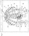
- Fig. 1 shows one embodiment of the containment structure 10 of the present invention and its method of use in an embodiment where such structure 10 is used for collecting a first fluid 12 (in the embodiment shown, leaking hydrocarbon fluids and gases) escaping from a compromised oil well 16, which results in the separation of collected fluid 12 from surrounding seawater 13 and allows pumping of such collected fluid 12 without enrtrained seawater to a vessel 17 at surface.
- a first fluid 12 in the embodiment shown, leaking hydrocarbon fluids and gases
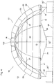
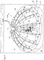
- Fig. 5 shows another embodiment of the containment structure 10 and Fig. 7 shows yet another variation of the hemispherical dome containment structure 10 of the present invention and its method of deployment.
- the containment structure 10 shown in each of Fig.s 1 & 5 is shown in a particular use to which it is particularly suited (but not necessarily only capable of being used in), namely as a sub-sea structure for containing and collecting therewithin a first fluid 12 , which may take the form of liquid and/or gaseous hydrocarbons which are escaping/leaking from compromised under-sea structure such as capped oil well 16, and displacing seawater 13 within such hemispherical dome 10 to thereby allow such first fluid 12 (to the exclusion or partial exclusion of any surrounding water 13 ) to be pumped to vessel 17 at surface.
- a first fluid 12 which may take the form of liquid and/or gaseous hydrocarbons which are escaping/leaking from compromised under-sea structure such as capped oil well 16, and displacing seawater 13 within such hemispherical dome 10 to thereby allow such first fluid 12 (to the exclusion or partial exclusion of any surrounding water 13 ) to be pumped to vessel 17 at surface.
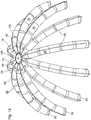
- containment structure 10 comprises a central hub member 18 having an outer periphery 20, which central hub 18 is situated centrally on or within a flexible fabric/ textile containment sheet 22.
- a plurality of elongate, inflatable beam members 25 are provided-- first longitudinal ends 26 thereof being arranged circumferentially around outer periphery 20 of hub member 18 and (when inflated) extend radially outwardly and (when tethered to one or more anchor members 32 ) extend in a downwardly-curved manner from central hub 18.
- Inflatable beam members 25 may overlie textile containment sheet 22 as best shown in Fig'.s 2-6, or alternatively may underlie textile containment sheet 22 as shown in Fig. 7 .
- Textile containment sheeting 22 is affixed to beam members 25 at discrete points (not shown) or continuously along a longitudinal length 27 of each inflatable beam member 25 (ref. Fig. 1 , 2 , and 8 ).
- an external fly in the form of a further flexible textile sheeting may further be placed over and external to beam members 25, so that the hemispherical dome structure 10 further assumes the external appearance of the dome 10 shown in Fig. 7 .
- Inflatable beam members 25 may similarly further be attached at discrete points or along a longitudinal length 27 thereof, in the similar manner by which such beams 25 are coupled to textile containment sheeting 22.
- inflatable beam members 25 underlie textile containment sheet 22, and internal fly (not shown) may be applied to an underside of inflatable beams 25, to provide a secondary manner of preventing leakage of collected first fluids from within hemispherical dome structure 10.
- Textile containment sheet 22 is preferably impervious or substantially impervious to the (first) fluid being collected therewithin, which as mentioned above, is typically oil and gaseous hydrocarbons.
- hydrocarbons may further contain toxic and acidic gases such as hydrogen sulfide
- One or more anchor members 32 are further provided, to allow textile containment sheet 22 and/or beam members to be tethered thereto, via rope, chain, or cables 28, to retain the textile containment sheet 22 and beam members proximate to and in a desired position around and directly above the point of compromise of sub-sea structure 16.
- Such one or more anchor members 32 may comprise a single unitary structure 32' of substantial mass, typically but not necessarily of cylindrical in shape, which is adapted to rest on the ground or a sea-bed floor 99, as shown in Fig. 5 .
- the hollow open interior 33 of such unitary anchor member 32 thereof is of a size sufficient to encircle or substantially surround compromised structure 16 which is leaking/spewing said first fluids 12, as shown in Fig. 5 .
- Textile containment sheet 22 and/or beam members 25 may be tethered to unitary anchor member 32' via rope, chain, or cable members 28, as shown for example in Fig.'s 5 & 6.
- anchor members 32 are formed of cast concrete which is particularly suitable for anchoring containment structure 10 to the seabed floor 99 due to its high density and the ability to cast attachment points 77 within such concrete for attaching the tethers 28 on an upperside of such anchor members 32, but other high density anchor members may instead be used.
- anchor members 32 may comprise steel spikes or pegs, adapted for being driven into the seabed floor 99, having a protruding end to which tethers 28 may be secured..
- one or more anchor members 32 may comprise a plurality of anchor members 32".
- one or both of textile containment sheeting 22 and/or one or more beam members 25 may be tethered via tether means 28 such as a rope, chain, or cable member to such anchor members 32" as shown in Figs. 1-4 and Figs. 7-9 , so as to secure the hemispherical dome in position around and above leaking undersea structure 16.
- a fluid exit port 130 may be located at the crown or apex of the containment structure 10 and typically located in the central hub 18, for allowing first fluids 12 flowing into the containment structure to rise and displace water downwardly, and thereafter be removed via pumping from such containment structure 10 to surface.
- Beam members 25, when inflated with a second fluid 50 typically comprising water or air, and preferably a combination of both.
- gases other than air may be employed, such as carbon dioxide or nitrogen, for the purposes of pressurizing beam members 25 where added resiliency of such beam members is desired.
- greater gaseous inflation pressures are needed to withstand greater hydrostatic forces imposed on such beams with increased depths.
- the increased inflation pressures particularly if such inflation of beam members is conducted at depth and not at surface, does not necessarily translate into inceased ball thickness of the inflatable beam members, as the increased inflation pressure will be offset by increased hydrostatic forces at depth.
- beam members 25 support textile containment sheet 22 in a downwardly-extending shape extending downwardly from said raised central hub 18, to form an enclosure 10 having an open bottom end 40 above compromised undersea structure 16.
- the containment structure 10 comprises a hemispherical dome, as best shown in Figs. 1 , 3 , 4 & 5 , and beam members 25 extend radially outwardly therefrom and when second longitudinal ends 30 thereof are tethered to anchor members 32, extend downwardly in a curved manner from central hub 18.
- beam members 25 support textile containment sheet 22 to which such beam members 25 are coupled, in a hemispherical dome shape having an open bottom end 40.
- each of said beam members are provided with a separate receptacle 70 for injection of the second fluid 50, Fig. 12 ..
- Each of receptacles 70 are in fluid communication respectively with an interior of a corresponding of the inflatable beam members 75 and further having a fluid coupling means (shown in Fig. 10 as reference 71 but said fluid coupling menas mounted on receptacles 70 not shown in Fig. 12 as being mounted on receptacles 70 thereof), typically a threaded fluid coupling as well known to persons of skill in the art, thereon to allow a supply hose (not shown) to be coupled to receptacle 70 and thereby permit the second fluid 50 to be pumped into each of said inflatable beam members 25.
- each receptacle 70 thereon further possessing a one -way valve 90 to allow said second fluid, once injected in a respective of said plurality of inflatable beam members 25, to be retained therein and prevented from escaping.
- Beam members 25 may be inflated at surface by supply of second fluid 50 to each of receptacles 70, or by an undersea submersible vessel individually and successively coupling a supply of said second fluid 50 to each receptacle 70.
- central hub 18 is provided with port means 101 thereon, In this regard, reference is to be had to Figs. 10 & 11 , showing this preferred configuration of central hub member 18.
- central hub 18 in addition to containing a fluid exit port 130 to allow removal of first fluids 12 from containment structure 10 further serves as a fluid distribution manifold for distributing second fluid 50 to each of beam members 25 to inflate same.
- central hub 18 is fluidly coupled to first longitudinal ends 26 of each of beam members 25.
- port means 101 comprises a plurality of ports 102 spaced about outer periphery 20 of central hub 18, such plurality of ports typically corresponding in number to the number of inflatable beam members 25.
- Each of ports 102 are coupled to and in fluid communication respectively with a first longitudinal end 26 of corresponding of inflatable beam members 25, and in fluid communication with each other via a communicating plenum 73.
- Supply of second fluid 50 via a supply hose (not shown) which is coupled to inlet spigot 71 on central hub 18 allows central hub 25 to simultaneously inflate beam members 25 via ports 102 therein.
- Such embodiment is particularly advantageous, as it allows the option of coupling a supply hose to inlet spigot 71 at surface, lowering the containment structure 10 so as to position it over the compromised structure 16, and inflating beam members 25 at depth and simultaneously, without the need for use of a submersible vessel to couple the fluid supply hose to each individual beam member 25.
- central hub 18 is provided with a plurality of one-way valves 90, preferably at the location of each of ports 102, as shown schematically in Fig. 11 .
- Each of one-way valves 90 allow flow of second fluid 50 from within central hub 18 and plenum 73 thereof to a respective of inflatable beam members 25, but prevent reverse flow of second fluid from any of inflatable beam members 25 into central hub 18.
- One way valve members 90 may comprise any type of ball valve, flapper-type valve, or the like as are well known in the art which functions as a check valve to only allow supply of second fluids 50 to the individual beam members 25 , and avoids depressurization of all beam members 25 in the event of a leak in one such beam member 25.
- a flexible , hollow, tubular fluid transport riser 120 is typically coupled to exterior surface of central hub 18, so as to receive and allow pumped removal of first fluids 12 via fluid exit port 130 in central hub 18.
- Central hub 18 is in fluid communication with an interior of containment enclosure 10 via fluid exit port 130.
- Riser 120 is preferably a flexible hose, and of a length sufficient to extend to surface to surface vessel 17, and allows pumping of first fluid 12 from an interior of said enclosure 10 to said surface.
- inflatable beam members 25 are couple to textile containment sheet 22 by having disposed around a portion of a circumference thereof and in spaced-apart relation along a longitudinal length 27 of each a plurality of circumferential strap members 80. Each inflatable beam member 25 is coupled to textile containment sheet via a point of coupling on each of said plurality of circumferential strap members thereon.
- the step of attaching the one or more anchor members 32 to said second mutually opposite longitudinal ends 30 of each of inflatable beam members 25 is conducted at surface and prior to lowering textile containment sheet 22, inflatable beam members 25, and central hub member 18 within said body of water to overly at least portions of said compromised sub-sea structure 16.
- the step of attaching the one or more anchor members 32 to the second mutually opposite longitudinal ends 30 of each of inflatable beam members 25 is conducted at depth, and after lowering textile containment sheet 22, inflatable beam members 25, and central hub member 18 within said body of water to overly at least portions of said compromised sub-sea structure 16.
- inflatable beam members 25 are inflated with second fluid 50 at surface and prior lowering textile containment sheet 22, inflatable beam members 25, and central hub member 18 within the body of water.
- inflatable beam members 25 are inflated subsea after having lowered textile containment sheet 22, inflatable beam members 25, and central hub member 18 within the body of water so as to at least partially overly said compromised sub-sea structure 16, and after having attached anchor means 32 to the second longitudinal ends of inflatable beam members 25.
- Such embodiment is particularly advantageous when employed with a central hub 18 having ports 102 thereon coupled to and in fluid communication with first longitudinal ends and having fluid inlet spigot 71 thereon coupled to a fluid supply hose supplying second fluid 50.
- beam members 25 may be inflated and containment structure 10 erected upon fluid supply hose supplying second fluids 50 from surface.
- the method may comprise utilizing an undersea submersible vessel (not shown) which is configured to allow supply of second fluid 50 to the receptacles 70.
Landscapes
- Engineering & Computer Science (AREA)
- General Engineering & Computer Science (AREA)
- Environmental & Geological Engineering (AREA)
- Mining & Mineral Resources (AREA)
- Geology (AREA)
- Life Sciences & Earth Sciences (AREA)
- Civil Engineering (AREA)
- Structural Engineering (AREA)
- Fluid Mechanics (AREA)
- Physics & Mathematics (AREA)
- Mechanical Engineering (AREA)
- Architecture (AREA)
- General Life Sciences & Earth Sciences (AREA)
- Geochemistry & Mineralogy (AREA)
- Chemical & Material Sciences (AREA)
- Oil, Petroleum & Natural Gas (AREA)
- Earth Drilling (AREA)
- Tents Or Canopies (AREA)
Claims (12)
- Structure de confinement (10) ayant une partie centrale surélevée et une extrémité inférieure ouverte, comprenant :(i) une feuille de confinement textile (22) sensiblement imperméable à un premier fluide (12) ;(ii) un moyeu central (18) situé centralement sur ladite feuille de confinement textile (22) et ayant une périphérie extérieure (20) ;(iii) un support pour supporter ladite feuille de confinement textile (22) en une forme de dôme hémisphérique incurvé vers le bas s'étendant vers le bas à partir du moyeu central (18), le support comprenant :
une pluralité d'éléments de poutre gonflables allongés (25), des premières extrémités longitudinales (26) de la pluralité d'éléments de poutre gonflables allongés (25) agencées circonférentiellement autour de ladite périphérie extérieure (20) dudit moyeu central (18), lesdits éléments de poutre gonflables (25) s'étendant chacun radialement vers l'extérieur et d'une manière s'étendant vers le bas à partir dudit moyeu central (18) et chacun sous-jacent ou sus-jacent par rapport à ladite feuille de confinement textile (22) et chacun couplé à ladite feuille de confinement textile (22) au niveau d'un ou plusieurs intervalles ou en continu le long d'une longueur longitudinale (27) de chacun desdits éléments de poutre gonflables (25) et supportant ainsi ladite feuille de confinement textile (22) ; et(iv) un ou plusieurs éléments d'ancrage (32'), chacun de ladite pluralité d'éléments de poutre gonflables (25) étant attaché, à proximité d'une seconde extrémité longitudinale (30) de celui-ci opposée à ladite première extrémité longitudinale (26), via des éléments de corde, de câble ou de chaîne (28), auxdits un ou plusieurs éléments d'ancrage (32') ; et(v) un orifice de sortie de fluide (130) situé dans ou au niveau dudit moyeu central, pour éliminer ledit premier fluide (12) de l'intérieur de ladite structure de confinement (10) ; dans laquelle lesdits éléments de poutre gonflables (25), lorsqu'ils sont gonflés avec un second fluide (50) et lorsque lesdites secondes extrémités longitudinales (30) de ceux-ci sont attachés auxdits un ou plusieurs éléments d'ancrage (32'), supportent ensemble ladite feuille de confinement textile (22) dans la forme s'étendant vers le bas qui s'étend vers le bas à partir dudit moyeu central, pour former une enceinte ayant une extrémité inférieure ouverte (40),
dans laquelle, lorsque lesdits éléments de poutre gonflables (25) sont gonflés, ladite structure de confinement (10) est déformable élastiquement de ladite extrémité inférieure ouverte (40) audit moyeu central (18),
dans laquelle ledit moyeu central (18) comprend :une pluralité d'orifices (102) espacés autour de la périphérie extérieure (20) et correspondant en nombre au nombre d'éléments de poutre gonflables (25), chaque orifice (102) étant couplé à et en communication fluidique avec la première extrémité longitudinale (26) d'un premier respectif des éléments de poutre gonflable (25), la pluralité d'orifices (102) étant configurés pour fournir ledit second fluide à un intérieur de chacun desdits éléments de poutre gonflable (25) afin de gonfler simultanément lesdits éléments de poutre gonflable (25) ; etun robinet d'entrée (71) agencé pour se coupler à un flexible d'alimentation afin de fournir une alimentation dudit second fluide. - Structure de confinement selon la revendication 1, dans laquelle lesdits éléments de poutre gonflables (25), lorsqu'ils sont gonflés avec un second fluide (50) et lorsque lesdites secondes extrémités longitudinales (30) de ceux-ci sont attachés auxdits un ou plusieurs éléments d'ancrage (32'), supportent ensemble ladite feuille de confinement textile (22) dans une forme de dôme hémisphérique incurvé vers le bas de sorte que l'enceinte a une forme de dôme hémisphérique ayant l'extrémité ouverte (40).
- Structure de confinement selon la revendication 1 ou la revendication 2, dans laquelle chacun desdits éléments de poutre est pourvu d'un réceptacle séparé (70) pour une injection dudit second fluide (50), chacun desdits réceptacles en communication fluidique respectivement avec un intérieur de l'un correspondant desdits éléments de poutre gonflables et ayant en outre des moyens de couplage de fluide (71) sur celui-ci pour permettre à un flexible d'alimentation d'être couplé à un tel réceptacle (70) et ainsi permettre audit second fluide (50) d'être pompé dans chacun desdits éléments de poutre gonflables, chaque réceptacle sur ceux-ci possédant en outre une vanne unidirectionnelle (90) pour permettre audit second fluide, une fois injecté dans l'un respectif de ladite pluralité d'éléments de poutre gonflables, d'y être retenu et de ne pas pouvoir s'en échapper.
- Structure de confinement selon l'une quelconque des revendications 1 à 3, dans laquelle ledit moyeu central (18) a des moyens d'orifice (101) situés sur sa périphérie extérieure (20), lesdits moyens d'orifice (101) étant configurés pour fournir ledit second fluide à un intérieur de chacun desdits éléments de poutre gonflables.
- Structure de confinement selon l'une quelconque des revendications 1 à 4, dans laquelle lesdits un ou plusieurs éléments d'ancrage comprennent un ou plusieurs éléments en béton coulé.
- Structure de confinement selon l'une quelconque des revendications 1 à 5, dans laquelle lesdits éléments de poutre gonflables sont couplés à ladite feuille de confinement textile via un point de couplage sur une pluralité d'éléments de sangle circonférentielle (110) disposés le long de ladite longueur longitudinale de chacun desdits éléments de poutre gonflables.
- Structure de confinement selon l'une quelconque des revendications 1 à 6, comprenant en outre une colonne montante de transport de fluide tubulaire creuse flexible (120), en communication fluidique avec un intérieur de ladite enceinte, configurée et d'une longueur suffisante pour s'étendre jusqu'à une surface lorsque ladite structure de confinement est immergée sous la mer, afin de transporter ledit premier fluide depuis l'intérieur de ladite enceinte jusqu'à ladite surface.
- Structure de confinement selon l'une quelconque des revendications 1 à 7, dans laquelle ledit moyeu central est couplé à un flexible d'alimentation en fluide allongé, et ledit moyeu central, lorsqu'il est alimenté avec ledit second fluide via ledit flexible d'alimentation en fluide, est configuré pour fournir ledit second fluide à un intérieur de chacun desdits éléments de poutre gonflables via ledit moyeu central de manière à gonfler lesdits éléments de poutre gonflables.
- Structure de confinement selon les revendications 1 à 8, dans laquelle ledit moyeu central (18), lorsqu'il est alimenté avec ledit second fluide via ledit flexible d'alimentation en fluide, est configuré pour fournir ledit second fluide à un intérieur de chacun desdits éléments de poutre gonflables de manière à mettre sous pression lesdits éléments de poutre gonflables à une pression uniforme.
- Structure de confinement selon l'une quelconque des revendications 1 à 9, dans laquelle ledit moyeu central est pourvu d'une pluralité de vannes unidirectionnelles (90) chacune de ladite pluralité de vannes unidirectionnelles permettant un écoulement dudit second fluide depuis l'intérieur dudit moyeu central vers l'un respectif desdits éléments de poutre gonflables, mais empêchant un écoulement inverse dudit second fluide depuis lesdits éléments de poutre gonflables jusque dans ledit moyeu central.
- Procédé pour confiner et récupérer un premier fluide (12) qui fuit ou s'écoule d'une structure immergée compromise (16), comprenant les étapes consistant à :(i) agencer en surface une pluralité d'éléments de poutre gonflables allongés (25) circonférentiellement autour d'une périphérie extérieure (20) d'un élément de moyeu central (18) de telle sorte que des premières extrémités longitudinales (26) desdits éléments de poutre gonflables (25) sont couplées audit élément de moyeu central (18) et des secondes extrémités longitudinales (30) mutuellement opposées de chacun desdits éléments de poutre gonflables (25) s'étendent radialement vers l'extérieur et vers le bas à partir dudit élément de moyeu central (18), dans lequel ledit moyeu central (18) comprend :une pluralité d'orifices (102) espacés autour de la périphérie extérieure (20) et correspondant en nombre au nombre d'éléments de poutre gonflables (25), chaque orifice (102) étant couplé à et en communication fluidique avec la première extrémité longitudinale (26) de l'un respectif des éléments de poutre gonflables (25), la pluralité d'orifices (102) étant configurée pour fournir un second fluide à un intérieur de chacun desdits éléments de poutre gonflables (25) ; etun robinet d'entrée (71) couplé à un flexible d'alimentation pour fournir une alimentation dudit second fluide ;(ii) agencer ledit élément de moyeu central (18) et lesdits éléments de poutre gonflables (25) de sorte qu'ils sont sous-jacents ou sus-jacents par rapport à une feuille de confinement textile (22) ;(iii) fixer lesdits éléments de poutre gonflables (25) à ladite feuille de confinement textile (22) en des points discrets ou en continu le long d'une longueur longitudinale (27) de chaque élément de poutre gonflable (25) ;(iv) coupler une première extrémité d'une colonne montante tubulaire allongée (120) audit élément de moyeu central (18), tout en maintenant une seconde extrémité longitudinale mutuellement opposée de ladite colonne montante tubulaire (120) en surface ;(v) abaisser ladite feuille de confinement textile (22), lesdits éléments de poutre gonflables (25) et ledit élément de moyeu central (18) au sein d'un plan d'eau pour recouvrir au moins partiellement une structure sous-marine compromise (16) d'où ledit premier fluide (12) fuit dans ledit plan d'eau, de sorte que ladite feuille de confinement textile (22) entoure des régions supérieures de ladite structure compromise (16) ;(vi) gonfler simultanément, après l'étape (v), lesdits éléments de poutre gonflables (25) avec ledit second fluide (50) pour former une structure de confinement (10) avec ledit élément de moyeu central (18) situé au niveau d'une couronne ou d'un sommet de ladite structure de confinement (10) ;(vii) fixer un ou plusieurs éléments d'ancrage auxdites secondes extrémités longitudinales mutuellement opposées de chacun desdits éléments de poutre gonflables, pour former un support afin de supporter ladite feuille de confinement textile (22) dans une forme de dôme hémisphérique incurvé vers le bas s'étendant vers le bas à partir du moyeu central (18), pour former une enceinte ayant une extrémité inférieure ouverte (40), le support comprenant lesdits éléments de poutre gonflables fixés auxdits éléments d'ancrage ;(viii) faire s'écouler ledit premier fluide (12) dans des régions sous-jacentes à ladite feuille de confinement textile (22) ; et(ix) retirer, au niveau d'un emplacement proche d'une couronne ou d'un sommet de ladite structure de confinement (10), ledit premier fluide (12) depuis un intérieur de ladite structure de confinement (10) via ladite colonne montante tubulaire (120), et pomper ledit premier fluide (12) vers la surface,dans lequel, lorsque lesdits éléments de poutre gonflables (25) sont gonflés, ladite structure de confinement (10) est déformable élastiquement de ladite extrémité inférieure ouverte (40) audit moyeu central (18).
- Procédé pour confiner et récupérer ledit premier fluide qui fuit de ladite structure sous-marine compromise selon la revendication 11, dans lequel :
lesdits éléments de poutre gonflables sont gonflés avec de l'air, de l'eau ou un mélange de ceux-ci par un navire sous-marin submersible, ledit navire sous-marin étant configuré pour alimenter, en ledit air, ladite eau ou un mélange de ceux-ci, un réceptacle sur un ou plusieurs desdits éléments de poutre gonflables, et alimenter, en ledit air, ladite eau ou un mélange de ceux-ci, ledit réceptacle pour ainsi gonfler lesdits éléments de poutre gonflables.
Applications Claiming Priority (1)
| Application Number | Priority Date | Filing Date | Title |
|---|---|---|---|
| CA2927192A CA2927192C (fr) | 2016-04-14 | 2016-04-14 | Une structure de confinement gonflable et methode de recuperation d'hydrocarbures ou de liquides toxiques fuyant d'une structure sous la mer |
Publications (2)
| Publication Number | Publication Date |
|---|---|
| EP3231987A1 EP3231987A1 (fr) | 2017-10-18 |
| EP3231987B1 true EP3231987B1 (fr) | 2020-11-25 |
Family
ID=56119856
Family Applications (1)
| Application Number | Title | Priority Date | Filing Date |
|---|---|---|---|
| EP17166531.8A Not-in-force EP3231987B1 (fr) | 2016-04-14 | 2017-04-13 | Structure de confinement gonflable et procédé de récupération d'hydrocarbures ou de fluides toxiques fuyant d'une structure sous-marine |
Country Status (3)
| Country | Link |
|---|---|
| US (1) | US10400411B2 (fr) |
| EP (1) | EP3231987B1 (fr) |
| CA (1) | CA2927192C (fr) |
Families Citing this family (6)
| Publication number | Priority date | Publication date | Assignee | Title |
|---|---|---|---|---|
| US9267765B2 (en) * | 2009-12-14 | 2016-02-23 | Dynamic Shelters Inc. | Tethermast and frag wall |
| RU2723799C1 (ru) * | 2019-06-21 | 2020-06-17 | Публичное акционерное общество "Нефтяная компания "Роснефть" (ПАО "НК "Роснефть") | Устройство типа "Купол" для ликвидации подводных разливов нефти в комплекте с технологическим оборудованием |
| US20210222454A1 (en) * | 2020-01-08 | 2021-07-22 | True Timber Outdoors Holding Company, Llc | Shelter with inflatable frame |
| CN113719189B (zh) * | 2021-09-30 | 2025-01-07 | 厦门忠信达工贸有限公司 | 一种高强度充气支撑构件 |
| CA3254223A1 (fr) * | 2022-03-17 | 2023-09-21 | Wobbleworks, Inc. | Structures gonflables modulaires |
| FR3152111B1 (fr) * | 2023-08-18 | 2025-10-24 | Michelin & Cie | Elément allongé de révolution gonflable à air captif comprenant un harnais |
Family Cites Families (28)
| Publication number | Priority date | Publication date | Assignee | Title |
|---|---|---|---|---|
| US547119A (en) * | 1895-10-01 | Of birmingham | ||
| US2297150A (en) * | 1940-12-31 | 1942-09-29 | Robert H Hunter | Tent |
| US2383840A (en) * | 1942-11-06 | 1945-08-28 | Glenn L Martin Co | Underwater fuel storage system |
| US2837101A (en) | 1955-04-28 | 1958-06-03 | Nina Bary | Inflatable structure |
| US3389559A (en) * | 1965-05-17 | 1968-06-25 | Campbell F. Logan | Fluid recovery system and method |
| US3653215A (en) * | 1969-06-04 | 1972-04-04 | Cerebro Dynamics Inc | Method and apparatus for confining and collecting oil leakage |
| US3981154A (en) * | 1969-11-25 | 1976-09-21 | Arcadia Refining Company | System for recovering petroleum fluids from underwater fissures |
| US3675427A (en) * | 1969-11-25 | 1972-07-11 | Arcadia Refining Co | Underwater storage device |
| US3664136A (en) * | 1969-11-28 | 1972-05-23 | Laval Claude C | Collecting device for submarine oil leakage |
| US3875753A (en) * | 1971-03-18 | 1975-04-08 | Bernd Ehlers | Underwater house |
| US3824942A (en) * | 1972-01-17 | 1974-07-23 | Chicago Bridge & Iron Co | Offshore underwater storage tank |
| US3999333A (en) * | 1975-11-14 | 1976-12-28 | Amarantos John G | Inflatable enclosure |
| US4876829A (en) * | 1988-01-19 | 1989-10-31 | Pneumo-Beam International Ltd. | Inflatable tent structure |
| EP0494053A1 (fr) | 1990-12-31 | 1992-07-08 | EUROVINIL INDUSTRIES S.p.A. | Construction sous forme d'un hangar ou d'une remise à structure porteuse pneumatique |
| US5570544A (en) | 1994-11-10 | 1996-11-05 | Hale; Gary A. | Inflatable structure |
| US5864767A (en) | 1997-06-09 | 1999-01-26 | The United States Of America As Represented By The Secretary Of The Army | Chemical biological explosive containment system |
| US5964767A (en) | 1997-09-12 | 1999-10-12 | Tapia; Eduardo Armando | Hollow sealable device for temporary or permanent surgical placement through a bone to provide a passageway into a cavity or internal anatomic site in a mammal |
| US6019112A (en) | 1998-03-05 | 2000-02-01 | Matlock; Cameron Arthur | Home greenhouse kit |
| FR2795109B1 (fr) * | 1999-06-18 | 2001-09-07 | Geocean Solmarine | Procede et dispositif de detection, localisation et captage de source d'eau douce en mer |
| US6192633B1 (en) * | 1999-09-10 | 2001-02-27 | Clint J. Hilbert | Rapidly deployable protective enclosure |
| GB2396335B (en) | 2002-12-21 | 2007-07-04 | Dominic Michaelis | Shipwreck cover |
| JP2004287118A (ja) | 2003-03-24 | 2004-10-14 | Hitachi Ltd | 表示装置 |
| USD510118S1 (en) * | 2004-10-22 | 2005-09-27 | Smith Justin D | Tent having integral inflatable supporting ribs |
| US7716876B2 (en) | 2006-05-19 | 2010-05-18 | Johnson Outdoors Inc. | Catapult air beam with permanently affixed laceloops |
| US20090249701A1 (en) * | 2008-04-02 | 2009-10-08 | Jean-Marc Daniel Turcot | Inflatable quonset and domed structures and the like |
| US8991104B2 (en) | 2008-09-05 | 2015-03-31 | Dynamic Shelters Inc. | Method and apparatus for distributing a load about an air beam |
| US9267765B2 (en) | 2009-12-14 | 2016-02-23 | Dynamic Shelters Inc. | Tethermast and frag wall |
| US8523482B1 (en) * | 2011-03-04 | 2013-09-03 | Michael Ray Watson, Sr. | On demand non-rigid underwater oil and gas containment and retrieval system and method |
-
2016
- 2016-04-14 CA CA2927192A patent/CA2927192C/fr active Active
- 2016-05-02 US US15/144,321 patent/US10400411B2/en not_active Expired - Fee Related
-
2017
- 2017-04-13 EP EP17166531.8A patent/EP3231987B1/fr not_active Not-in-force
Non-Patent Citations (1)
| Title |
|---|
| None * |
Also Published As
| Publication number | Publication date |
|---|---|
| US20170298587A1 (en) | 2017-10-19 |
| CA2927192C (fr) | 2016-12-13 |
| CA2927192A1 (fr) | 2016-06-17 |
| EP3231987A1 (fr) | 2017-10-18 |
| US10400411B2 (en) | 2019-09-03 |
Similar Documents
| Publication | Publication Date | Title |
|---|---|---|
| EP3231987B1 (fr) | Structure de confinement gonflable et procédé de récupération d'hydrocarbures ou de fluides toxiques fuyant d'une structure sous-marine | |
| US7882794B2 (en) | Buoyancy device and method for stabilizing and controlling lowering or raising of a structure between the surface and the sea floor | |
| US7008141B2 (en) | Collapsible buoyancy device for risers on offshore structures | |
| US20110274496A1 (en) | Undersea leak remediation device and method | |
| Pimm et al. | Design and testing of energy bags for underwater compressed air energy storage | |
| US8523482B1 (en) | On demand non-rigid underwater oil and gas containment and retrieval system and method | |
| US9051704B2 (en) | Cold water piping system including an articulating interface, modular elements, and strainer assembly | |
| US20120027517A1 (en) | Fluid leak containment system | |
| US20130195555A1 (en) | Device for capturing and conducting away liquids and/or gases escaping from a bed of a body of water | |
| US20050235921A1 (en) | Self-deployable open ocean aquaculture cages and underwater structures | |
| CN109594806B (zh) | 一种具有救生功能的游泳池 | |
| KR20140005840A (ko) | 수중 유정 분출 여파로 오일 유출에 대항하는 방법 및 이 방법을 수행하는 시설 | |
| US20070089656A1 (en) | Device and a method for stabilizing and controlling the lowering or raising of a structure between the surface and the bed of the sea | |
| US20120121335A1 (en) | Deepwater containment system with surface separator and method of using same | |
| US20120080194A1 (en) | Method and apparatus for capturing oil leaking from an underwater well | |
| US8911176B2 (en) | Subsea crude oil and/or gas containment and recovery system and method | |
| CN205327369U (zh) | 一种橡胶打捞浮筒 | |
| US20220282444A1 (en) | Watercraft | |
| US20120213587A1 (en) | Deepwater containment systems with flexible riser and methods of using same | |
| US3641771A (en) | Apparatus and method for confining and collecting oil floating on a water surface | |
| US20120037063A1 (en) | Subsea collection and containment system for hydrocarbon emissions. | |
| US3080844A (en) | Maritime salvage equipment | |
| US20110293375A1 (en) | Deepwater Oil Containment Methods and Structures, Underwater Oil Containment Bubbles, Domes, Tents, Bags and Other Flexible Structures | |
| EP3174783B1 (fr) | Système de tuyauterie d'eau froide comprenant une interface d'articulation, des éléments modulaires et un ensemble crépine | |
| CN109944495A (zh) | 一种用于潜在地质灾害发生区域的生命帐篷及使用方法 |
Legal Events
| Date | Code | Title | Description |
|---|---|---|---|
| PUAI | Public reference made under article 153(3) epc to a published international application that has entered the european phase |
Free format text: ORIGINAL CODE: 0009012 |
|
| STAA | Information on the status of an ep patent application or granted ep patent |
Free format text: STATUS: THE APPLICATION HAS BEEN PUBLISHED |
|
| AK | Designated contracting states |
Kind code of ref document: A1 Designated state(s): AL AT BE BG CH CY CZ DE DK EE ES FI FR GB GR HR HU IE IS IT LI LT LU LV MC MK MT NL NO PL PT RO RS SE SI SK SM TR |
|
| AX | Request for extension of the european patent |
Extension state: BA ME |
|
| STAA | Information on the status of an ep patent application or granted ep patent |
Free format text: STATUS: REQUEST FOR EXAMINATION WAS MADE |
|
| 17P | Request for examination filed |
Effective date: 20180418 |
|
| RBV | Designated contracting states (corrected) |
Designated state(s): AL AT BE BG CH CY CZ DE DK EE ES FI FR GB GR HR HU IE IS IT LI LT LU LV MC MK MT NL NO PL PT RO RS SE SI SK SM TR |
|
| STAA | Information on the status of an ep patent application or granted ep patent |
Free format text: STATUS: EXAMINATION IS IN PROGRESS |
|
| 17Q | First examination report despatched |
Effective date: 20180801 |
|
| GRAP | Despatch of communication of intention to grant a patent |
Free format text: ORIGINAL CODE: EPIDOSNIGR1 |
|
| STAA | Information on the status of an ep patent application or granted ep patent |
Free format text: STATUS: GRANT OF PATENT IS INTENDED |
|
| INTG | Intention to grant announced |
Effective date: 20191125 |
|
| GRAS | Grant fee paid |
Free format text: ORIGINAL CODE: EPIDOSNIGR3 |
|
| GRAA | (expected) grant |
Free format text: ORIGINAL CODE: 0009210 |
|
| STAA | Information on the status of an ep patent application or granted ep patent |
Free format text: STATUS: THE PATENT HAS BEEN GRANTED |
|
| AK | Designated contracting states |
Kind code of ref document: B1 Designated state(s): AL AT BE BG CH CY CZ DE DK EE ES FI FR GB GR HR HU IE IS IT LI LT LU LV MC MK MT NL NO PL PT RO RS SE SI SK SM TR |
|
| REG | Reference to a national code |
Ref country code: GB Ref legal event code: FG4D |
|
| REG | Reference to a national code |
Ref country code: CH Ref legal event code: EP |
|
| REG | Reference to a national code |
Ref country code: AT Ref legal event code: REF Ref document number: 1338512 Country of ref document: AT Kind code of ref document: T Effective date: 20201215 |
|
| REG | Reference to a national code |
Ref country code: DE Ref legal event code: R096 Ref document number: 602017028077 Country of ref document: DE |
|
| REG | Reference to a national code |
Ref country code: IE Ref legal event code: FG4D |
|
| REG | Reference to a national code |
Ref country code: AT Ref legal event code: MK05 Ref document number: 1338512 Country of ref document: AT Kind code of ref document: T Effective date: 20201125 |
|
| REG | Reference to a national code |
Ref country code: NL Ref legal event code: MP Effective date: 20201125 |
|
| PG25 | Lapsed in a contracting state [announced via postgrant information from national office to epo] |
Ref country code: FI Free format text: LAPSE BECAUSE OF FAILURE TO SUBMIT A TRANSLATION OF THE DESCRIPTION OR TO PAY THE FEE WITHIN THE PRESCRIBED TIME-LIMIT Effective date: 20201125 Ref country code: GR Free format text: LAPSE BECAUSE OF FAILURE TO SUBMIT A TRANSLATION OF THE DESCRIPTION OR TO PAY THE FEE WITHIN THE PRESCRIBED TIME-LIMIT Effective date: 20210226 Ref country code: NO Free format text: LAPSE BECAUSE OF FAILURE TO SUBMIT A TRANSLATION OF THE DESCRIPTION OR TO PAY THE FEE WITHIN THE PRESCRIBED TIME-LIMIT Effective date: 20210225 Ref country code: PT Free format text: LAPSE BECAUSE OF FAILURE TO SUBMIT A TRANSLATION OF THE DESCRIPTION OR TO PAY THE FEE WITHIN THE PRESCRIBED TIME-LIMIT Effective date: 20210325 Ref country code: RS Free format text: LAPSE BECAUSE OF FAILURE TO SUBMIT A TRANSLATION OF THE DESCRIPTION OR TO PAY THE FEE WITHIN THE PRESCRIBED TIME-LIMIT Effective date: 20201125 |
|
| PG25 | Lapsed in a contracting state [announced via postgrant information from national office to epo] |
Ref country code: SE Free format text: LAPSE BECAUSE OF FAILURE TO SUBMIT A TRANSLATION OF THE DESCRIPTION OR TO PAY THE FEE WITHIN THE PRESCRIBED TIME-LIMIT Effective date: 20201125 Ref country code: IS Free format text: LAPSE BECAUSE OF FAILURE TO SUBMIT A TRANSLATION OF THE DESCRIPTION OR TO PAY THE FEE WITHIN THE PRESCRIBED TIME-LIMIT Effective date: 20210325 Ref country code: LV Free format text: LAPSE BECAUSE OF FAILURE TO SUBMIT A TRANSLATION OF THE DESCRIPTION OR TO PAY THE FEE WITHIN THE PRESCRIBED TIME-LIMIT Effective date: 20201125 Ref country code: PL Free format text: LAPSE BECAUSE OF FAILURE TO SUBMIT A TRANSLATION OF THE DESCRIPTION OR TO PAY THE FEE WITHIN THE PRESCRIBED TIME-LIMIT Effective date: 20201125 Ref country code: BG Free format text: LAPSE BECAUSE OF FAILURE TO SUBMIT A TRANSLATION OF THE DESCRIPTION OR TO PAY THE FEE WITHIN THE PRESCRIBED TIME-LIMIT Effective date: 20210225 Ref country code: AT Free format text: LAPSE BECAUSE OF FAILURE TO SUBMIT A TRANSLATION OF THE DESCRIPTION OR TO PAY THE FEE WITHIN THE PRESCRIBED TIME-LIMIT Effective date: 20201125 |
|
| REG | Reference to a national code |
Ref country code: LT Ref legal event code: MG9D |
|
| PG25 | Lapsed in a contracting state [announced via postgrant information from national office to epo] |
Ref country code: HR Free format text: LAPSE BECAUSE OF FAILURE TO SUBMIT A TRANSLATION OF THE DESCRIPTION OR TO PAY THE FEE WITHIN THE PRESCRIBED TIME-LIMIT Effective date: 20201125 |
|
| PG25 | Lapsed in a contracting state [announced via postgrant information from national office to epo] |
Ref country code: CZ Free format text: LAPSE BECAUSE OF FAILURE TO SUBMIT A TRANSLATION OF THE DESCRIPTION OR TO PAY THE FEE WITHIN THE PRESCRIBED TIME-LIMIT Effective date: 20201125 Ref country code: EE Free format text: LAPSE BECAUSE OF FAILURE TO SUBMIT A TRANSLATION OF THE DESCRIPTION OR TO PAY THE FEE WITHIN THE PRESCRIBED TIME-LIMIT Effective date: 20201125 Ref country code: LT Free format text: LAPSE BECAUSE OF FAILURE TO SUBMIT A TRANSLATION OF THE DESCRIPTION OR TO PAY THE FEE WITHIN THE PRESCRIBED TIME-LIMIT Effective date: 20201125 Ref country code: SM Free format text: LAPSE BECAUSE OF FAILURE TO SUBMIT A TRANSLATION OF THE DESCRIPTION OR TO PAY THE FEE WITHIN THE PRESCRIBED TIME-LIMIT Effective date: 20201125 Ref country code: SK Free format text: LAPSE BECAUSE OF FAILURE TO SUBMIT A TRANSLATION OF THE DESCRIPTION OR TO PAY THE FEE WITHIN THE PRESCRIBED TIME-LIMIT Effective date: 20201125 Ref country code: RO Free format text: LAPSE BECAUSE OF FAILURE TO SUBMIT A TRANSLATION OF THE DESCRIPTION OR TO PAY THE FEE WITHIN THE PRESCRIBED TIME-LIMIT Effective date: 20201125 |
|
| REG | Reference to a national code |
Ref country code: DE Ref legal event code: R097 Ref document number: 602017028077 Country of ref document: DE |
|
| PG25 | Lapsed in a contracting state [announced via postgrant information from national office to epo] |
Ref country code: DK Free format text: LAPSE BECAUSE OF FAILURE TO SUBMIT A TRANSLATION OF THE DESCRIPTION OR TO PAY THE FEE WITHIN THE PRESCRIBED TIME-LIMIT Effective date: 20201125 |
|
| PLBE | No opposition filed within time limit |
Free format text: ORIGINAL CODE: 0009261 |
|
| STAA | Information on the status of an ep patent application or granted ep patent |
Free format text: STATUS: NO OPPOSITION FILED WITHIN TIME LIMIT |
|
| PG25 | Lapsed in a contracting state [announced via postgrant information from national office to epo] |
Ref country code: IT Free format text: LAPSE BECAUSE OF FAILURE TO SUBMIT A TRANSLATION OF THE DESCRIPTION OR TO PAY THE FEE WITHIN THE PRESCRIBED TIME-LIMIT Effective date: 20201125 Ref country code: AL Free format text: LAPSE BECAUSE OF FAILURE TO SUBMIT A TRANSLATION OF THE DESCRIPTION OR TO PAY THE FEE WITHIN THE PRESCRIBED TIME-LIMIT Effective date: 20201125 Ref country code: NL Free format text: LAPSE BECAUSE OF FAILURE TO SUBMIT A TRANSLATION OF THE DESCRIPTION OR TO PAY THE FEE WITHIN THE PRESCRIBED TIME-LIMIT Effective date: 20201125 |
|
| 26N | No opposition filed |
Effective date: 20210826 |
|
| REG | Reference to a national code |
Ref country code: DE Ref legal event code: R119 Ref document number: 602017028077 Country of ref document: DE |
|
| PG25 | Lapsed in a contracting state [announced via postgrant information from national office to epo] |
Ref country code: SI Free format text: LAPSE BECAUSE OF FAILURE TO SUBMIT A TRANSLATION OF THE DESCRIPTION OR TO PAY THE FEE WITHIN THE PRESCRIBED TIME-LIMIT Effective date: 20201125 Ref country code: MC Free format text: LAPSE BECAUSE OF FAILURE TO SUBMIT A TRANSLATION OF THE DESCRIPTION OR TO PAY THE FEE WITHIN THE PRESCRIBED TIME-LIMIT Effective date: 20201125 |
|
| GBPC | Gb: european patent ceased through non-payment of renewal fee |
Effective date: 20210413 |
|
| PG25 | Lapsed in a contracting state [announced via postgrant information from national office to epo] |
Ref country code: LU Free format text: LAPSE BECAUSE OF NON-PAYMENT OF DUE FEES Effective date: 20210413 |
|
| REG | Reference to a national code |
Ref country code: BE Ref legal event code: MM Effective date: 20210430 |
|
| PG25 | Lapsed in a contracting state [announced via postgrant information from national office to epo] |
Ref country code: ES Free format text: LAPSE BECAUSE OF FAILURE TO SUBMIT A TRANSLATION OF THE DESCRIPTION OR TO PAY THE FEE WITHIN THE PRESCRIBED TIME-LIMIT Effective date: 20201125 Ref country code: GB Free format text: LAPSE BECAUSE OF NON-PAYMENT OF DUE FEES Effective date: 20210413 Ref country code: FR Free format text: LAPSE BECAUSE OF NON-PAYMENT OF DUE FEES Effective date: 20210430 Ref country code: LI Free format text: LAPSE BECAUSE OF NON-PAYMENT OF DUE FEES Effective date: 20210430 Ref country code: DE Free format text: LAPSE BECAUSE OF NON-PAYMENT OF DUE FEES Effective date: 20211103 Ref country code: CH Free format text: LAPSE BECAUSE OF NON-PAYMENT OF DUE FEES Effective date: 20210430 |
|
| PG25 | Lapsed in a contracting state [announced via postgrant information from national office to epo] |
Ref country code: IE Free format text: LAPSE BECAUSE OF NON-PAYMENT OF DUE FEES Effective date: 20210413 |
|
| PG25 | Lapsed in a contracting state [announced via postgrant information from national office to epo] |
Ref country code: IS Free format text: LAPSE BECAUSE OF FAILURE TO SUBMIT A TRANSLATION OF THE DESCRIPTION OR TO PAY THE FEE WITHIN THE PRESCRIBED TIME-LIMIT Effective date: 20210325 |
|
| PG25 | Lapsed in a contracting state [announced via postgrant information from national office to epo] |
Ref country code: BE Free format text: LAPSE BECAUSE OF NON-PAYMENT OF DUE FEES Effective date: 20210430 |
|
| PG25 | Lapsed in a contracting state [announced via postgrant information from national office to epo] |
Ref country code: HU Free format text: LAPSE BECAUSE OF FAILURE TO SUBMIT A TRANSLATION OF THE DESCRIPTION OR TO PAY THE FEE WITHIN THE PRESCRIBED TIME-LIMIT; INVALID AB INITIO Effective date: 20170413 |
|
| PG25 | Lapsed in a contracting state [announced via postgrant information from national office to epo] |
Ref country code: CY Free format text: LAPSE BECAUSE OF FAILURE TO SUBMIT A TRANSLATION OF THE DESCRIPTION OR TO PAY THE FEE WITHIN THE PRESCRIBED TIME-LIMIT Effective date: 20201125 |
|
| PG25 | Lapsed in a contracting state [announced via postgrant information from national office to epo] |
Ref country code: MK Free format text: LAPSE BECAUSE OF FAILURE TO SUBMIT A TRANSLATION OF THE DESCRIPTION OR TO PAY THE FEE WITHIN THE PRESCRIBED TIME-LIMIT Effective date: 20201125 |
|
| PG25 | Lapsed in a contracting state [announced via postgrant information from national office to epo] |
Ref country code: MT Free format text: LAPSE BECAUSE OF FAILURE TO SUBMIT A TRANSLATION OF THE DESCRIPTION OR TO PAY THE FEE WITHIN THE PRESCRIBED TIME-LIMIT Effective date: 20201125 |
|
| PG25 | Lapsed in a contracting state [announced via postgrant information from national office to epo] |
Ref country code: TR Free format text: LAPSE BECAUSE OF FAILURE TO SUBMIT A TRANSLATION OF THE DESCRIPTION OR TO PAY THE FEE WITHIN THE PRESCRIBED TIME-LIMIT Effective date: 20201125 |