EP3231990A1 - Appareil pour l'usinage de composants de moteurs à turbine à gaz - Google Patents
Appareil pour l'usinage de composants de moteurs à turbine à gaz Download PDFInfo
- Publication number
- EP3231990A1 EP3231990A1 EP17165021.1A EP17165021A EP3231990A1 EP 3231990 A1 EP3231990 A1 EP 3231990A1 EP 17165021 A EP17165021 A EP 17165021A EP 3231990 A1 EP3231990 A1 EP 3231990A1
- Authority
- EP
- European Patent Office
- Prior art keywords
- flexible pipe
- tool head
- head part
- tool
- gas turbine
- Prior art date
- Legal status (The legal status is an assumption and is not a legal conclusion. Google has not performed a legal analysis and makes no representation as to the accuracy of the status listed.)
- Withdrawn
Links
Images




Classifications
-
- B—PERFORMING OPERATIONS; TRANSPORTING
- B23—MACHINE TOOLS; METAL-WORKING NOT OTHERWISE PROVIDED FOR
- B23Q—DETAILS, COMPONENTS, OR ACCESSORIES FOR MACHINE TOOLS, e.g. ARRANGEMENTS FOR COPYING OR CONTROLLING; MACHINE TOOLS IN GENERAL CHARACTERISED BY THE CONSTRUCTION OF PARTICULAR DETAILS OR COMPONENTS; COMBINATIONS OR ASSOCIATIONS OF METAL-WORKING MACHINES, NOT DIRECTED TO A PARTICULAR RESULT
- B23Q5/00—Driving or feeding mechanisms; Control arrangements therefor
- B23Q5/02—Driving main working members
- B23Q5/04—Driving main working members rotary shafts, e.g. working-spindles
- B23Q5/06—Driving main working members rotary shafts, e.g. working-spindles driven essentially by fluid pressure or pneumatic power
-
- B—PERFORMING OPERATIONS; TRANSPORTING
- B25—HAND TOOLS; PORTABLE POWER-DRIVEN TOOLS; MANIPULATORS
- B25J—MANIPULATORS; CHAMBERS PROVIDED WITH MANIPULATION DEVICES
- B25J9/00—Program-controlled manipulators
- B25J9/06—Program-controlled manipulators characterised by multi-articulated arms
- B25J9/065—Snake robots
-
- F—MECHANICAL ENGINEERING; LIGHTING; HEATING; WEAPONS; BLASTING
- F01—MACHINES OR ENGINES IN GENERAL; ENGINE PLANTS IN GENERAL; STEAM ENGINES
- F01D—NON-POSITIVE DISPLACEMENT MACHINES OR ENGINES, e.g. STEAM TURBINES
- F01D5/00—Blades; Blade-carrying members; Heating, heat-insulating, cooling or antivibration means on the blades or the members
- F01D5/005—Repairing methods or devices
-
- B—PERFORMING OPERATIONS; TRANSPORTING
- B23—MACHINE TOOLS; METAL-WORKING NOT OTHERWISE PROVIDED FOR
- B23B—TURNING; BORING
- B23B45/00—Hand-held or like portable drilling machines, e.g. drill guns; Equipment therefor
- B23B45/003—Attachments
- B23B45/005—Flexible shafts
-
- B—PERFORMING OPERATIONS; TRANSPORTING
- B23—MACHINE TOOLS; METAL-WORKING NOT OTHERWISE PROVIDED FOR
- B23B—TURNING; BORING
- B23B45/00—Hand-held or like portable drilling machines, e.g. drill guns; Equipment therefor
- B23B45/04—Hand-held or like portable drilling machines, e.g. drill guns; Equipment therefor driven by fluid-pressure or pneumatic power
- B23B45/042—Turbine motors
-
- B—PERFORMING OPERATIONS; TRANSPORTING
- B24—GRINDING; POLISHING
- B24B—MACHINES, DEVICES, OR PROCESSES FOR GRINDING OR POLISHING; DRESSING OR CONDITIONING OF ABRADING SURFACES; FEEDING OF GRINDING, POLISHING, OR LAPPING AGENTS
- B24B23/00—Portable grinding machines, e.g. hand-guided; Accessories therefor
- B24B23/02—Portable grinding machines, e.g. hand-guided; Accessories therefor with rotating grinding tools; Accessories therefor
- B24B23/026—Fluid driven
-
- B—PERFORMING OPERATIONS; TRANSPORTING
- B24—GRINDING; POLISHING
- B24B—MACHINES, DEVICES, OR PROCESSES FOR GRINDING OR POLISHING; DRESSING OR CONDITIONING OF ABRADING SURFACES; FEEDING OF GRINDING, POLISHING, OR LAPPING AGENTS
- B24B47/00—Drives or gearings; Equipment therefor
- B24B47/10—Drives or gearings; Equipment therefor for rotating or reciprocating working-spindles carrying grinding wheels or workpieces
- B24B47/14—Drives or gearings; Equipment therefor for rotating or reciprocating working-spindles carrying grinding wheels or workpieces by liquid or gas pressure
-
- B—PERFORMING OPERATIONS; TRANSPORTING
- B25—HAND TOOLS; PORTABLE POWER-DRIVEN TOOLS; MANIPULATORS
- B25J—MANIPULATORS; CHAMBERS PROVIDED WITH MANIPULATION DEVICES
- B25J11/00—Manipulators not otherwise provided for
- B25J11/005—Manipulators for mechanical processing tasks
-
- B—PERFORMING OPERATIONS; TRANSPORTING
- B25—HAND TOOLS; PORTABLE POWER-DRIVEN TOOLS; MANIPULATORS
- B25J—MANIPULATORS; CHAMBERS PROVIDED WITH MANIPULATION DEVICES
- B25J18/00—Arms
- B25J18/007—Arms the end effector rotating around a fixed point
-
- B—PERFORMING OPERATIONS; TRANSPORTING
- B25—HAND TOOLS; PORTABLE POWER-DRIVEN TOOLS; MANIPULATORS
- B25J—MANIPULATORS; CHAMBERS PROVIDED WITH MANIPULATION DEVICES
- B25J18/00—Arms
- B25J18/06—Arms flexible
-
- B—PERFORMING OPERATIONS; TRANSPORTING
- B25—HAND TOOLS; PORTABLE POWER-DRIVEN TOOLS; MANIPULATORS
- B25J—MANIPULATORS; CHAMBERS PROVIDED WITH MANIPULATION DEVICES
- B25J19/00—Accessories fitted to manipulators, e.g. for monitoring, for viewing; Safety devices combined with or specially adapted for use in connection with manipulators
- B25J19/0025—Means for supplying energy to the end effector
-
- B—PERFORMING OPERATIONS; TRANSPORTING
- B25—HAND TOOLS; PORTABLE POWER-DRIVEN TOOLS; MANIPULATORS
- B25J—MANIPULATORS; CHAMBERS PROVIDED WITH MANIPULATION DEVICES
- B25J9/00—Program-controlled manipulators
- B25J9/10—Program-controlled manipulators characterised by positioning means for manipulator elements
- B25J9/1075—Program-controlled manipulators characterised by positioning means for manipulator elements with muscles or tendons
-
- F—MECHANICAL ENGINEERING; LIGHTING; HEATING; WEAPONS; BLASTING
- F01—MACHINES OR ENGINES IN GENERAL; ENGINE PLANTS IN GENERAL; STEAM ENGINES
- F01D—NON-POSITIVE DISPLACEMENT MACHINES OR ENGINES, e.g. STEAM TURBINES
- F01D15/00—Adaptations of machines or engines for special use; Combinations of engines with devices driven thereby
- F01D15/06—Adaptations for driving, or combinations with, hand-held tools or the like control thereof
-
- F—MECHANICAL ENGINEERING; LIGHTING; HEATING; WEAPONS; BLASTING
- F01—MACHINES OR ENGINES IN GENERAL; ENGINE PLANTS IN GENERAL; STEAM ENGINES
- F01D—NON-POSITIVE DISPLACEMENT MACHINES OR ENGINES, e.g. STEAM TURBINES
- F01D5/00—Blades; Blade-carrying members; Heating, heat-insulating, cooling or antivibration means on the blades or the members
- F01D5/12—Blades
-
- F—MECHANICAL ENGINEERING; LIGHTING; HEATING; WEAPONS; BLASTING
- F01—MACHINES OR ENGINES IN GENERAL; ENGINE PLANTS IN GENERAL; STEAM ENGINES
- F01D—NON-POSITIVE DISPLACEMENT MACHINES OR ENGINES, e.g. STEAM TURBINES
- F01D9/00—Stators
- F01D9/02—Nozzles; Nozzle boxes; Stator blades; Guide conduits, e.g. individual nozzles
-
- F—MECHANICAL ENGINEERING; LIGHTING; HEATING; WEAPONS; BLASTING
- F04—POSITIVE - DISPLACEMENT MACHINES FOR LIQUIDS; PUMPS FOR LIQUIDS OR ELASTIC FLUIDS
- F04D—NON-POSITIVE-DISPLACEMENT PUMPS
- F04D29/00—Details, component parts, or accessories
- F04D29/26—Rotors specially for elastic fluids
- F04D29/32—Rotors specially for elastic fluids for axial flow pumps
- F04D29/321—Rotors specially for elastic fluids for axial flow pumps for axial flow compressors
- F04D29/324—Blades
-
- F—MECHANICAL ENGINEERING; LIGHTING; HEATING; WEAPONS; BLASTING
- F04—POSITIVE - DISPLACEMENT MACHINES FOR LIQUIDS; PUMPS FOR LIQUIDS OR ELASTIC FLUIDS
- F04D—NON-POSITIVE-DISPLACEMENT PUMPS
- F04D29/00—Details, component parts, or accessories
- F04D29/40—Casings; Connections of working fluid
- F04D29/52—Casings; Connections of working fluid for axial pumps
- F04D29/54—Fluid-guiding means, e.g. diffusers
- F04D29/541—Specially adapted for elastic fluid pumps
- F04D29/542—Bladed diffusers
-
- B—PERFORMING OPERATIONS; TRANSPORTING
- B23—MACHINE TOOLS; METAL-WORKING NOT OTHERWISE PROVIDED FOR
- B23B—TURNING; BORING
- B23B2215/00—Details of workpieces
- B23B2215/76—Components for turbines
-
- B—PERFORMING OPERATIONS; TRANSPORTING
- B23—MACHINE TOOLS; METAL-WORKING NOT OTHERWISE PROVIDED FOR
- B23B—TURNING; BORING
- B23B2260/00—Details of constructional elements
- B23B2260/068—Flexible members
-
- B—PERFORMING OPERATIONS; TRANSPORTING
- B23—MACHINE TOOLS; METAL-WORKING NOT OTHERWISE PROVIDED FOR
- B23B—TURNING; BORING
- B23B2270/00—Details of turning, boring or drilling machines, processes or tools not otherwise provided for
- B23B2270/02—Use of a particular power source
- B23B2270/027—Pneumatics
-
- F—MECHANICAL ENGINEERING; LIGHTING; HEATING; WEAPONS; BLASTING
- F05—INDEXING SCHEMES RELATING TO ENGINES OR PUMPS IN VARIOUS SUBCLASSES OF CLASSES F01-F04
- F05D—INDEXING SCHEME FOR ASPECTS RELATING TO NON-POSITIVE-DISPLACEMENT MACHINES OR ENGINES, GAS-TURBINES OR JET-PROPULSION PLANTS
- F05D2220/00—Application
- F05D2220/30—Application in turbines
- F05D2220/32—Application in turbines in gas turbines
-
- F—MECHANICAL ENGINEERING; LIGHTING; HEATING; WEAPONS; BLASTING
- F05—INDEXING SCHEMES RELATING TO ENGINES OR PUMPS IN VARIOUS SUBCLASSES OF CLASSES F01-F04
- F05D—INDEXING SCHEME FOR ASPECTS RELATING TO NON-POSITIVE-DISPLACEMENT MACHINES OR ENGINES, GAS-TURBINES OR JET-PROPULSION PLANTS
- F05D2230/00—Manufacture
- F05D2230/10—Manufacture by removing material
-
- F—MECHANICAL ENGINEERING; LIGHTING; HEATING; WEAPONS; BLASTING
- F05—INDEXING SCHEMES RELATING TO ENGINES OR PUMPS IN VARIOUS SUBCLASSES OF CLASSES F01-F04
- F05D—INDEXING SCHEME FOR ASPECTS RELATING TO NON-POSITIVE-DISPLACEMENT MACHINES OR ENGINES, GAS-TURBINES OR JET-PROPULSION PLANTS
- F05D2230/00—Manufacture
- F05D2230/72—Maintenance
-
- F—MECHANICAL ENGINEERING; LIGHTING; HEATING; WEAPONS; BLASTING
- F05—INDEXING SCHEMES RELATING TO ENGINES OR PUMPS IN VARIOUS SUBCLASSES OF CLASSES F01-F04
- F05D—INDEXING SCHEME FOR ASPECTS RELATING TO NON-POSITIVE-DISPLACEMENT MACHINES OR ENGINES, GAS-TURBINES OR JET-PROPULSION PLANTS
- F05D2230/00—Manufacture
- F05D2230/80—Repairing, retrofitting or upgrading methods
Definitions
- the present disclosure concerns apparatus for machining components of gas turbine engines.
- Gas turbine engines may require maintenance and repair during their operational life.
- an aerofoil of a gas turbine engine (such as a compressor blade, a turbine blade, or a nozzle guide vane) may become damaged during operation and such damage may impair the performance of the gas turbine engine. It may be relatively time consuming and costly to disassemble the gas turbine engine to carry out the repair.
- apparatus for machining a component of a gas turbine engine comprising: a flexible pipe having a first end and a second end and defining a conduit for receiving a fluid; one or more first actuators arranged to enable the first end of the flexible pipe to be re-positioned relative to the second end of the flexible pipe; a turbine positioned adjacent to the first end of the flexible pipe, the turbine being arranged to receive fluid from the conduit of the flexible pipe; and a tool head coupled to the first end of the flexible pipe, the tool head comprising: a fastener arranged to fasten to a tool and to receive torque from the turbine.
- the turbine may be positioned within the tool head. Alternatively, the turbine may be positioned within the flexible pipe.
- the one or more first actuators may include one or more cables extending along at least a portion of the flexible pipe.
- the one or more first actuators may include one or more inflatable members extending along at least a portion of the flexible pipe.
- the tool head may include: a first tool head part coupled to the first end of the flexible pipe and having a first longitudinal axis; and a second tool head part coupled to the first tool head part and having a second longitudinal axis, the second tool head part comprising the fastener.
- the first tool head part and the second tool head part may be fixed in position relative to one another.
- the first longitudinal axis and the second longitudinal axis may define a non-zero angle there between.
- the tool head may further comprise a joint between the first tool head part and the second tool head part.
- the apparatus may further comprise one or more second actuators arranged to enable the second tool head part to be rotated relative to the first tool head part.
- the fluid may be air.
- the apparatus may further comprise a source of compressed air coupled to the conduit of the flexible pipe.
- Fig. 1 illustrates a schematic cross sectional side view of an apparatus 10 including a flexible pipe 12, one or more first actuators 14, a turbine 16 and a tool head 18.
- the apparatus 10 is arranged to machine one or more components of a gas turbine engine.
- the apparatus 10 may be inserted into the interior of a gas turbine engine via a borescope port to machine an aerofoil of the gas turbine engine (such as a compressor blade, a turbine blade, or a nozzle guide vane).
- the flexible pipe 12 may comprise any suitable materials and have any suitable structure.
- the flexible pipe 12 may comprise a flexible coiled material and an external sheath.
- the flexible pipe 12 may be braided to provide additional strength.
- the flexible pipe 12 is elongate and has a first end 20 and a second opposite end 22.
- the flexible pipe 12 may have any cross sectional shape when viewed from the front.
- the flexible pipe 12 may have a circular shape, an elliptical shape, or a polygonal shape when viewed from the front.
- the flexible pipe 12 defines a conduit 24 for receiving a fluid therein.
- the second end 22 may be coupled to a source of compressed fluid (compressed air for example) and fluid may flow from the second end 22 to the first end 20 (as indicated by arrow 25).
- the one or more first actuators 14 are arranged to enable the first end 20 of the flexible pipe 12 to be re-positioned relative to the second end 22 of the flexible pipe 12.
- the one or more first actuators 14 may include any suitable mechanism or device for controlling the shape of the flexible pipe 12 and may be positioned within the flexible pipe 12 or outside of the flexible pipe 12.
- the one or more first actuators 14 may include one or more cables that extend along at least a portion of the flexible pipe 12 and that may be operated (pulled for example) to re-position the first end 20 of the flexible pipe 12.
- the one or more cables may be positioned and moveable within tubular cavities within the flexible pipe 12 and may be connected to the flexible pipe 12 at (or close to) the first end 20, or may be connected to the tool head 18.
- fig. 2 illustrates an apparatus 101 where the flexible pipe 12 defines four tubular cavities 26, each having a cable 28 therein so that the flexible pipe 12 has at least two degrees of freedom.
- the one or more first actuators 14 may include one or more inflatable members that extend along at least a portion of the flexible pipe 12 and that may be inflated (with air for example) to re-position the first end 20 of the flexible pipe 12.
- the one or more inflatable members may be positioned within tubular cavities within the flexible pipe 12.
- the term "flexible" means that the flexible pipe 12 has a stiffness along the length of the flexible pipe 12 that enables the flexible pipe 12 to change shape when a force is applied to the flexible pipe 12 by the one or more first actuators 14.
- the first end 20 of the flexible pipe 12 may be moved through (and no further than) an angle relative to the configuration illustrated in Fig. 1 .
- the angle may have any value between ten degrees and three hundred and sixty degrees.
- the flexible pipe 12 may be relatively rigid radially and may consequently not buckle and form kinks when reconfigured by the one or more actuators 14.
- the turbine 16 is positioned adjacent to the first end 20 of the flexible pipe 12 and is arranged to receive fluid from the conduit 24 of the flexible pipe 12.
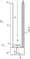
- the turbine 16 may be positioned within the tool head 18 (as illustrated in Fig. 1 ) or may be positioned within the flexible pipe 12 (as illustrated in fig. 3 where the apparatus 102 includes a turbine 16 located within the flexible pipe 12 at the first end 20).
- the turbine 16 is arranged to rotate when fluid flows through the turbine 16 (that is, the turbine 16 is driven by the flow of fluid through the turbine 16).
- the tool head 18 is coupled to the first end 20 of the flexible pipe 12 and includes a fastener 30 that is arranged to fasten to a tool (a blending tool, a milling tool, or a drill bit for example).
- the fastener 30 may have any suitable structure for fastening to a tool and may comprise a socket for receiving a tool therein, a chuck for clamping a tool, or a protrusion for being received within a socket of a tool.
- the fastener 30 is arranged to receive torque from the turbine 16 via a shaft 32 and may rotate at a relatively high angular speed (up to 400,000 revolutions per minute for example).
- the apparatus 10, 101, 102 may provide several advantages. First, the apparatus 10, 101, 102 may be inserted into the interior of a gas turbine engine via a borescope port to machine a component of the gas turbine engine.
- the tool head 18 of the apparatus 10, 101, 102 may be advantageously re-positioned within the gas turbine engine after the apparatus 10, 101, 102 has been inserted into the gas turbine engine through operation of the one or more first actuators 14. This may enable an operator (which may be a human or a robot) to machine a selected part of a component which is at a relatively inaccessible location within a gas turbine engine.
- the fastener 30 may have a relatively high angular speed since the fastener 30 is driven by the turbine 16. This may advantageously result in the apparatus 10, 101, 102 having a relatively high machining speed and may thus reduce the time required to machine a component. The high angular speed of the fastener 30 may also result in the apparatus 10, 101, 102 requiring a relatively low force to perform a machining operation.
- the angular speed of the fastener 30 may be relatively unaffected by the shape of the flexible pipe 12 since the conduit 24 remains open irrespective of the configuration of the flexible pipe 12. This may provide the apparatus 10, 101, 102 with a relatively high machining speed even when the flexible pipe 12 is deflected through a relatively large angle (such as ninety degrees from the configuration illustrated in Fig. 1 for example).
- Fig. 4 illustrates a schematic side view of another apparatus 103 for machining a component of a gas turbine engine according to various examples.
- the apparatus 103 is similar to the apparatus 10, 101, 102 and where the features are similar, the same reference numerals are used. It should be appreciated that various features of the apparatus 103 (such as the one or more actuators) are not illustrated in Fig. 4 to maintain the clarity of the figure.
- the apparatus 103 differs from the apparatus 10, 101, 102 in that the tool head 18 includes a first tool head part 181 and a second tool head part 182.
- the first tool head part 181 is coupled to the first end 20 of the flexible pipe 12 and has a first longitudinal axis 34.
- the second tool head part 182 is coupled to the first tool head part 181 and has a second longitudinal axis 36.
- the second tool head part 182 comprises the fastener 30 and may additionally comprise the turbine 16 and the shaft 32.
- the first tool head part 181 and the second tool head part 182 are fixed in position relative to one another.
- the first tool head part 181 and the second tool head part 182 may be welded together.
- the first tool head part 181 and the second tool head part 182 may be coupled to one another via an adhesive.
- the first longitudinal axis 34 and the second longitudinal axis 36 define a non-zero angle 38 there between.
- the angle 38 may be any angle between ten degrees and ninety degrees.
- the apparatus 103 may provide a further advantage in that the tool head 18 may have an angle 38 that makes it more suitable for machining a particular component of a gas turbine engine.
- the angle of the tool head 18 may enable access to a particular part of a component or may enable the apparatus 103 to provide a greater force to a component during machining.
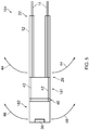
- Fig. 5 illustrates a schematic cross sectional side view of a further apparatus 104 for machining a component of a gas turbine engine according to various examples.
- the apparatus 104 is similar to the apparatus 103 and where the features are similar, the same reference numerals are used.
- the apparatus 104 differs from the apparatus 103 in that the first tool head part 181 and the second tool head part 182 are coupled to one another via a joint 40, and the second tool head part 182 may move relative to the first tool head part 181 (in other words, the tool head 18 is articulated).
- the joint 40 may be any suitable connection that allows movement between the first tool head part 181 and the second tool head part 182 in one or more degrees of freedom.
- the joint 40 may include, for example, a pivot joint or a hinge joint.
- the apparatus 104 also differs from the apparatus 103 in that the apparatus 104 further comprises one or more second actuators 42 that are arranged to enable the second tool head part 182 to be rotated relative to the first tool head part 181.
- the one or more second actuators 42 may comprise any suitable mechanism and may comprise, for example, one or more cables and/or one or more inflatable members.
- the apparatus 104 may be inserted into the interior of a gas turbine engine via a borescope port.
- the one or more first actuators 14 may be operated to re-position the first end 20 of the flexible pipe 12 as indicated by arrows 44.
- the one or more second actuators 42 may be operated to rotate the second tool head part 182 relative to the first tool head part 181 as indicated by arrows 46.
- the apparatus 104 may provide a further advantage in that articulation of the tool head 18 may enable the apparatus 104 to be used for a greater number of repair and maintenance operations within a gas turbine engine.
- the articulation of the tool head 18 may enable the second tool head part 182 to machine locations within a gas turbine engine that would be inaccessible to the apparatus 10, 101, 102, 103.
- Fig. 6 illustrates a schematic side view diagram of another apparatus 105 for machining a component of a gas turbine engine according to various examples.
- the apparatus 105 includes one of the apparatus 10, 101, 102, 103, 104 and additionally comprises a further flexible pipe 48, a controller 50, a source of compressed fluid 52, and a tool 53.
- the first end 20 of the flexible pipe 12 may be moved through an angle of one hundred and eighty degrees relative to the second end 22 of the flexible pipe 12. It should be appreciated that the flexible pipe 12 is not limited to this range of movement, and that in other examples, the flexible pipe 12 may move through an angle greater than, or less than, one hundred and eighty degrees.
- the further flexible pipe 48 is connected between the flexible pipe 12 and the controller 50.
- the further flexible pipe 48 may comprise the same material and have the same internal structure as the flexible pipe 12, or may comprise a different material and/or different internal structure.
- the controller 50 is arranged to control the operation of the one or more first actuators 14 (and the one or more second actuators 42 where the apparatus 105 includes the apparatus 104). Where the apparatus 105 is a hand operated tool, the controller 50 may include one or more handles 54 for controlling the first and second actuators 14, 42. Where the apparatus 105 is a robotic machining tool, the controller 50 may include one or more servomotors for controlling the operation of the first and second actuators 14, 42.
- the source of compressed fluid 52 is arranged to provide fluid to the flexible pipe 12 via the controller 50 and the further flexible pipe 48.
- the source of compressed fluid 52 is a source of compressed air.
- the tool 53 may be any suitable tool for machining a component of a gas turbine engine.
- the tool 53 may be a blending tool, a milling tool, or a drill bit.
Landscapes
- Engineering & Computer Science (AREA)
- Mechanical Engineering (AREA)
- General Engineering & Computer Science (AREA)
- Robotics (AREA)
- Physics & Mathematics (AREA)
- Fluid Mechanics (AREA)
- Health & Medical Sciences (AREA)
- General Health & Medical Sciences (AREA)
- Orthopedic Medicine & Surgery (AREA)
- Rheumatology (AREA)
- Electrical Discharge Machining, Electrochemical Machining, And Combined Machining (AREA)
- Structures Of Non-Positive Displacement Pumps (AREA)
Applications Claiming Priority (1)
| Application Number | Priority Date | Filing Date | Title |
|---|---|---|---|
| GB1606386.9A GB2549308A (en) | 2016-04-13 | 2016-04-13 | Apparatus for machining components of gas turbine engines |
Publications (1)
| Publication Number | Publication Date |
|---|---|
| EP3231990A1 true EP3231990A1 (fr) | 2017-10-18 |
Family
ID=58489619
Family Applications (1)
| Application Number | Title | Priority Date | Filing Date |
|---|---|---|---|
| EP17165021.1A Withdrawn EP3231990A1 (fr) | 2016-04-13 | 2017-04-05 | Appareil pour l'usinage de composants de moteurs à turbine à gaz |
Country Status (4)
| Country | Link |
|---|---|
| US (1) | US20170297156A1 (fr) |
| EP (1) | EP3231990A1 (fr) |
| GB (1) | GB2549308A (fr) |
| SG (1) | SG10201702850XA (fr) |
Families Citing this family (2)
| Publication number | Priority date | Publication date | Assignee | Title |
|---|---|---|---|---|
| EP3182103B1 (fr) * | 2015-12-17 | 2020-11-04 | Ansaldo Energia Switzerland AG | Gaine de boroscope |
| US11471947B2 (en) * | 2019-06-06 | 2022-10-18 | Raytheon Technologies Corporation | Apparatus and methods for improvement of surface geometries of internal channels of additively manufactured components |
Citations (7)
| Publication number | Priority date | Publication date | Assignee | Title |
|---|---|---|---|---|
| US4659195A (en) * | 1986-01-31 | 1987-04-21 | American Hospital Supply Corporation | Engine inspection system |
| US5155941A (en) * | 1989-09-18 | 1992-10-20 | Olympus Optical Co., Ltd. | Industrial endoscope system having a rotary treatment member |
| JPH0515485A (ja) * | 1991-01-25 | 1993-01-26 | Olympus Optical Co Ltd | 流体圧駆動型アクチユエータおよびこれを利用した内視鏡 |
| US5349940A (en) * | 1991-01-10 | 1994-09-27 | Olympus Optical Co., Ltd. | Endoscope system with a rotating treatment adapter at the end |
| US20050107001A1 (en) * | 2003-11-18 | 2005-05-19 | Dieter Moeller | Grinding apparatus for blending defects on turbine blades and associated method of use |
| EP1700672A1 (fr) * | 2005-03-07 | 2006-09-13 | HILTI Aktiengesellschaft | Adaptateur |
| US20100121141A1 (en) * | 2008-11-12 | 2010-05-13 | Michael Rontal | Endoscopic cutting and debriding device mounted on a flexible and maneuverable tube employing a fluid-driven turbine |
Family Cites Families (6)
| Publication number | Priority date | Publication date | Assignee | Title |
|---|---|---|---|---|
| DE19529668A1 (de) * | 1995-08-11 | 1997-02-13 | Kaltenbach & Voigt | Ärztliches oder zahnärztliches Turbinen-Handstück |
| DE50110915D1 (de) * | 2000-05-16 | 2006-10-19 | Storz Endoskop Gmbh | Austauschbarer Werkzeugeinsatz für ein endoskopisches Bearbeitungsgerät und derartiges endoskopisches Bearbeitungsgerät |
| GB0020461D0 (en) * | 2000-08-18 | 2000-10-11 | Oliver Crispin Consulting Ltd | Improvements in and relating to the robotic positioning of a work tool to a sensor |
| US7097539B2 (en) * | 2003-11-18 | 2006-08-29 | Dieter Moeller | Rotary grinding apparatus for blending defects on turbine blades and associated method of use |
| FR2896715B1 (fr) * | 2006-02-02 | 2009-12-25 | Mbh Dev | Equipement transportable destine a meuler, poncer, surfacer, incorporant un dispositif a fonctionnement par depression |
| GB201503683D0 (en) * | 2015-03-05 | 2015-04-22 | Rolls Royce Plc | A tool for machining an object |
-
2016
- 2016-04-13 GB GB1606386.9A patent/GB2549308A/en not_active Withdrawn
-
2017
- 2017-04-05 EP EP17165021.1A patent/EP3231990A1/fr not_active Withdrawn
- 2017-04-05 US US15/479,682 patent/US20170297156A1/en not_active Abandoned
- 2017-04-06 SG SG10201702850XA patent/SG10201702850XA/en unknown
Patent Citations (7)
| Publication number | Priority date | Publication date | Assignee | Title |
|---|---|---|---|---|
| US4659195A (en) * | 1986-01-31 | 1987-04-21 | American Hospital Supply Corporation | Engine inspection system |
| US5155941A (en) * | 1989-09-18 | 1992-10-20 | Olympus Optical Co., Ltd. | Industrial endoscope system having a rotary treatment member |
| US5349940A (en) * | 1991-01-10 | 1994-09-27 | Olympus Optical Co., Ltd. | Endoscope system with a rotating treatment adapter at the end |
| JPH0515485A (ja) * | 1991-01-25 | 1993-01-26 | Olympus Optical Co Ltd | 流体圧駆動型アクチユエータおよびこれを利用した内視鏡 |
| US20050107001A1 (en) * | 2003-11-18 | 2005-05-19 | Dieter Moeller | Grinding apparatus for blending defects on turbine blades and associated method of use |
| EP1700672A1 (fr) * | 2005-03-07 | 2006-09-13 | HILTI Aktiengesellschaft | Adaptateur |
| US20100121141A1 (en) * | 2008-11-12 | 2010-05-13 | Michael Rontal | Endoscopic cutting and debriding device mounted on a flexible and maneuverable tube employing a fluid-driven turbine |
Also Published As
| Publication number | Publication date |
|---|---|
| SG10201702850XA (en) | 2017-11-29 |
| US20170297156A1 (en) | 2017-10-19 |
| GB2549308A (en) | 2017-10-18 |
Similar Documents
| Publication | Publication Date | Title |
|---|---|---|
| US20240326266A1 (en) | Selectively flexible extension tool | |
| CA3058055C (fr) | Tube-rallonge selectivement souple | |
| US9869420B2 (en) | System and method for pipeline maintenance | |
| EP2829368B1 (fr) | Robot et son procédé de fabrication | |
| CN108568830B (zh) | 具有可重配的末端执行器组件的机器人系统 | |
| CN102000849B (zh) | 用于压缩机的装置和工具 | |
| EP2450158A1 (fr) | Structure de poignet de robot et robot | |
| US8459373B2 (en) | Modified power tool | |
| US12569947B2 (en) | Method and apparatus for servicing engines | |
| CN102832751A (zh) | 用于就地维修发电-电动机构件的设备和方法 | |
| EP3231990A1 (fr) | Appareil pour l'usinage de composants de moteurs à turbine à gaz | |
| JP2022177807A (ja) | 機構 | |
| JP2002530210A (ja) | パイプの清掃および再生技術のためのフライス装置 | |
| US7789167B2 (en) | Power assist lever arm attachment | |
| EP2289655A2 (fr) | Appareil et outils à utiliser avec des compresseurs | |
| EP3670113B1 (fr) | Dispositif de positionnement | |
| US20180147714A1 (en) | Multi-joint tools with cylindrical segments | |
| KR102915095B1 (ko) | 로봇을 통해 조립 작업을 실행하는 시스템 및 방법 | |
| CN120588143A (zh) | 伸缩插入工具 |
Legal Events
| Date | Code | Title | Description |
|---|---|---|---|
| PUAI | Public reference made under article 153(3) epc to a published international application that has entered the european phase |
Free format text: ORIGINAL CODE: 0009012 |
|
| STAA | Information on the status of an ep patent application or granted ep patent |
Free format text: STATUS: THE APPLICATION HAS BEEN PUBLISHED |
|
| AK | Designated contracting states |
Kind code of ref document: A1 Designated state(s): AL AT BE BG CH CY CZ DE DK EE ES FI FR GB GR HR HU IE IS IT LI LT LU LV MC MK MT NL NO PL PT RO RS SE SI SK SM TR |
|
| AX | Request for extension of the european patent |
Extension state: BA ME |
|
| STAA | Information on the status of an ep patent application or granted ep patent |
Free format text: STATUS: THE APPLICATION IS DEEMED TO BE WITHDRAWN |
|
| 18D | Application deemed to be withdrawn |
Effective date: 20180419 |