EP3232060B1 - Einwegpatrone für eine peristaltische mikropumpe und peristaltische mikropumpe - Google Patents
Einwegpatrone für eine peristaltische mikropumpe und peristaltische mikropumpe Download PDFInfo
- Publication number
- EP3232060B1 EP3232060B1 EP17166526.8A EP17166526A EP3232060B1 EP 3232060 B1 EP3232060 B1 EP 3232060B1 EP 17166526 A EP17166526 A EP 17166526A EP 3232060 B1 EP3232060 B1 EP 3232060B1
- Authority
- EP
- European Patent Office
- Prior art keywords
- housing
- pump
- disposable cartridge
- section
- flexible tube
- Prior art date
- Legal status (The legal status is an assumption and is not a legal conclusion. Google has not performed a legal analysis and makes no representation as to the accuracy of the status listed.)
- Not-in-force
Links
Images





Classifications
-
- F—MECHANICAL ENGINEERING; LIGHTING; HEATING; WEAPONS; BLASTING
- F04—POSITIVE - DISPLACEMENT MACHINES FOR LIQUIDS; PUMPS FOR LIQUIDS OR ELASTIC FLUIDS
- F04B—POSITIVE-DISPLACEMENT MACHINES FOR LIQUIDS; PUMPS
- F04B43/00—Machines, pumps, or pumping installations having flexible working members
- F04B43/12—Machines, pumps, or pumping installations having flexible working members having peristaltic action
-
- F—MECHANICAL ENGINEERING; LIGHTING; HEATING; WEAPONS; BLASTING
- F04—POSITIVE - DISPLACEMENT MACHINES FOR LIQUIDS; PUMPS FOR LIQUIDS OR ELASTIC FLUIDS
- F04B—POSITIVE-DISPLACEMENT MACHINES FOR LIQUIDS; PUMPS
- F04B43/00—Machines, pumps, or pumping installations having flexible working members
- F04B43/0009—Special features
- F04B43/0054—Special features particularities of the flexible members
- F04B43/0072—Special features particularities of the flexible members of tubular flexible members
-
- F—MECHANICAL ENGINEERING; LIGHTING; HEATING; WEAPONS; BLASTING
- F04—POSITIVE - DISPLACEMENT MACHINES FOR LIQUIDS; PUMPS FOR LIQUIDS OR ELASTIC FLUIDS
- F04B—POSITIVE-DISPLACEMENT MACHINES FOR LIQUIDS; PUMPS
- F04B43/00—Machines, pumps, or pumping installations having flexible working members
- F04B43/12—Machines, pumps, or pumping installations having flexible working members having peristaltic action
- F04B43/1253—Machines, pumps, or pumping installations having flexible working members having peristaltic action by using two or more rollers as squeezing elements, the rollers moving on an arc of a circle during squeezing
-
- F—MECHANICAL ENGINEERING; LIGHTING; HEATING; WEAPONS; BLASTING
- F04—POSITIVE - DISPLACEMENT MACHINES FOR LIQUIDS; PUMPS FOR LIQUIDS OR ELASTIC FLUIDS
- F04B—POSITIVE-DISPLACEMENT MACHINES FOR LIQUIDS; PUMPS
- F04B43/00—Machines, pumps, or pumping installations having flexible working members
- F04B43/12—Machines, pumps, or pumping installations having flexible working members having peristaltic action
- F04B43/1253—Machines, pumps, or pumping installations having flexible working members having peristaltic action by using two or more rollers as squeezing elements, the rollers moving on an arc of a circle during squeezing
- F04B43/1284—Means for pushing the backing-plate against the tubular flexible member
-
- A—HUMAN NECESSITIES
- A61—MEDICAL OR VETERINARY SCIENCE; HYGIENE
- A61M—DEVICES FOR INTRODUCING MEDIA INTO, OR ONTO, THE BODY; DEVICES FOR TRANSDUCING BODY MEDIA OR FOR TAKING MEDIA FROM THE BODY; DEVICES FOR PRODUCING OR ENDING SLEEP OR STUPOR
- A61M2205/00—General characteristics of the apparatus
- A61M2205/12—General characteristics of the apparatus with interchangeable cassettes forming partially or totally the fluid circuit
-
- A—HUMAN NECESSITIES
- A61—MEDICAL OR VETERINARY SCIENCE; HYGIENE
- A61M—DEVICES FOR INTRODUCING MEDIA INTO, OR ONTO, THE BODY; DEVICES FOR TRANSDUCING BODY MEDIA OR FOR TAKING MEDIA FROM THE BODY; DEVICES FOR PRODUCING OR ENDING SLEEP OR STUPOR
- A61M5/00—Devices for bringing media into the body in a subcutaneous, intra-vascular or intramuscular way; Accessories therefor, e.g. filling or cleaning devices, arm rests
- A61M5/14—Infusion devices, e.g. infusing by gravity; Blood infusion; Accessories therefor
- A61M5/142—Pressure infusion, e.g. using pumps
- A61M5/14212—Pumping with an aspiration and an expulsion action
- A61M5/14232—Roller pumps
Definitions
- the present disclosure refers to a disposable cartridge for a peristaltic micro pump and a peristaltic micro pump.
- the second main method is the control of the delivered volumes by using micro valves, which can be on ( Ohori et al., Sensors and Actuators A: Physical, vol. 64(1), pp. 57-62, 1998 ), ( Melin et al., Annual Review of Biophysics and Biomolecular Structure, vol. 36(1), pp. 213-231, 2007 ) or off chip (Bürkert, Buerkert Product overview 05 MicroFluidics, Ingelfingen, 2010). Combinations of both methods can also be found and an implementation of flow sensors is possible.
- WO 2011/057663 A1 discloses a hose cartridge for removably mounting a hose on a peristaltic pump comprising a roller wheel for pumping a fluid through said hose.
- the hose cartridge generally describes a closed loop encircling an opening through which the roller wheel extends when the hose cartridge is mounted on a peristaltic pump in a working position.
- a peristaltic pump assembly comprising a pump and a removable cassette
- the pump includes a pumping mechanism portion having opposed inner and outer walls defining a slot opening therebetween, and further having a cassette mounting pin extending at least partially across the slot opening.
- the removable cassette includes a cylindrical hinge journal and a mounting channel merging in a radial direction with the hinge journal, whereby the cassette is mounted on the mounting pin by inserting the removable cassette into the slot opening between the inner and outer walls of the pumping mechanism portion in a radial direction of the mounting pin such that the mounting pin is passed through the mounting channel and received by the hinge journal.
- the mounting pin and hinge journal are configured to allow the removable cassette to rotate about the mounting pin into and out of an installed position.
- a peristaltic pump assembly which includes a housing having a cassette receiving portion defined therein, a securing shaft positioned within the cassette receiving portion, and a cassette including a tube disposed therein selectively engageable with the cassette receiving portion.
- a knob removably engages a portion of the securing shaft and includes a tab extending therefrom configured to contact and compress the tube when in a disengagement position.
- the document JP 2001/200793 A describes a liquid delivering device provided with a body, having one press roller, and a liquid cassette for housing a liquid cartridge where a reserving body of delivery liquid is connected to one end of an elastic tube and a check valve is connected to the other end.
- the liquid cassette is mounted detachably, so as to receive press operation of the press roller on the elastic tube, and liquid is delivered for a constant amount, through the rotary motion of the press roller by repeating such operations that the press roller is pressed to the elastic tube, or it is not pressed.
- the document EP 0 339 857 A1 relates to a peristaltic pump having a plurality of removable cartridges, each containing a length of tubing, and each having means for adjusting occlusion comprising a linearly displaceable occlusion bed.
- Tubing retainers on each cartridge stabilise the tubing segments to constrain them against longitudinal displacement during pumping.
- Means are provided to enable visual determination of occlusion adjustment through the top of each cartridge.
- Each of the cartridges is reversible, and is readily installed on the pump frame and retained thereon by a snap-lock mechanism.
- peristaltic pump which peristaltic pump comprises, inter alia, an actuating part, a cartridge part comprising at least three chambers and mechanisms for controlling movement of the actuating part to and from the cartridge part to control opening or closing of the inlet and outlet to the chamber(s).
- a further peristaltic micro pump is known from JP-5125811 .
- This pump includes a detachable cartridge holding a tube.
- the tube is deformed in a pumping action by fingers pressing on the tube.
- the cartridge does not feature inlet and outlet connectors in its housing and at least one sealing element on each of opposite ends of the tube.
- a disposable cartridge for a peristaltic micro pump comprising: a housing; a inlet provided on the housing and comprising an inlet connector; an outlet provided on the housing and comprising an outlet connector; a fluid channel extending in the housing between the inlet and the outlet; a channel section of the fluid channel, the channel section provided by a flexible tube comprising at least one sealing element on each of opposite ends; one or more openings provided adjacent to the channel section in the housing in such a way that one or more pump engaging elements of a pump drive can engage with the flexible tube through the opening for compressing the flexible tube in a pumping process for pumping a fluid through the fluid channel; and a mounting device provided on the housing for detachably mounting the housing in a peristaltic micro pump housing.
- a peristaltic micro pump comprising a disposable cartridge.
- the flexible tube may be detachably received in a tube recess of the housing.
- the flexible tube may be non-detachably in the housing. It may be mounted at the time of assembling the disposable cartridge.
- the disposable cartridge may be disposed after use without removing the flexible tube.
- the flexible tube may comprise at least one of a curved tube section and a linear tube section configured to engage with the one or more pump engaging elements providing a linear pump element arrangement and a rotating pump element arrangement, respectively.
- the curved section may be provided in a curved recess of the housing. The curved section may extend over a half circle,
- the housing may comprise a curved housing section for receiving one or more engaging elements of the rotating pump element arrangement pro-vided on a rotor within the curved housing section, wherein a first opening is provided adjacent to the curved section in the rotor recess.
- the first opening may be provided on a narrow side of the housing.
- the housing may comprise a linear recess for receiving the linear tube section, wherein a second opening is provided adjacent to the linear tube section.
- the disposable cartridge may be configured at least one of a linear pump element arrangement and a rotating pump element arrangement. Also, a combination of at least one linear pump element arrangement and at least one rotating pump element arrangement may be provided.
- the second opening may be provided on a flat side of the housing.
- the flexible tube may comprise a plurality of flexible sub-tubes, each of the flexible sub-tubes received in a separate sub-recess of the housing and providing for a channel sub-section of the fluid channel.
- the one or more sealing elements may comprise a flange extension or section in at least one end section.
- the flexible tube may be form-fitted received in the recess.
- the flexible tube may comprise a flange extension in at least one end section or in both end sections.
- the disposable cartridge may further comprise a fluid reservoir provided in the housing and having a fluid connection to the fluid channel.
- a novel disposable high pressure peristaltic micro pump which allows a precise dosing of single volumes in the nanolitre range.
- the flexible tube is integrated into a single use or disposable cartridge, which offers numerous advantages.
- a high pressure can be generated, while a small internal volume gives opportunity to handle expensive or rare fluids. Its small size allows the implementation into biochips or micro fluidic systems.
- a standalone solution can be connected to semi flexible tubes or pipes. The fluidic properties of the pump and the achievable maximum pressure have been determined. The fatigue resistance of the cartridge has been verified. Its simple structure offers the potential for mass production.
- a modular assembly for a peristaltic micro pump may be provided, wherein the peristaltic micro pump comprises the disposable cartridge module and a driving module provided with a motor and one or more pump engaging elements.
- the disposable cartridge which may be a modular assembly itself, at least some of the elements, such as the housing or the flexible tube, may be provided as casted elements made of plastic.
- the disposable cartridge may be integrated into a microchip, for example as part of a LOC (Lab on a chip) or ⁇ TAS (micro Total Analysis Systems) device.
- LOC Lab on a chip
- ⁇ TAS micro Total Analysis Systems
- Connectors may be provided, among others, for bayonet mount connections, self-securing plug connections, threaded connections or combinations thereof. Alternatively or additionally, one or more connectors may be fixed to elements such as a reservoir, a valve, a nozzle, or a flexible or rigid tube.
- the fluid channel extending in the housing as whole may be comprised of the flexible tube fixed in the housing.
- the flexible tube may protrude from the housing. Protruding ends may provide for connecting to other elements. One end of the flexible tube may protrude from the housing while the other end is connected to a reservoir fixed to the housing.
- the disposable cartridge may be provided as a stackable cartridge in such a way that one or more pump engaging elements may engage with a plurality of disposable cartridges to form a plurality of peristaltic micro pumps.
- a peristaltic micro pump having a disposable cartridge is described in further detail by referring to Fig. 1 to 7 .
- the peristaltic micro pump can be provided as a standalone device or a device for integration into different kinds of micro fluidic chips. It provides a precise dosage of small volumes and can be easily discarded after use.
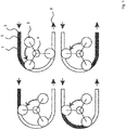
- Fig. 1 shows a schematic representation of working principles of a standard peristaltic pump.
- a channel section 1 of a fluid channel the channel section provided by a flexible tube.
- a fluid to be pumped is fed to in inlet 2.
- Pump engaging elements 3 are provided on a rotor 4.
- the pump engaging elements 3 are provided as rollers.
- a pumping sequence is shown in Fig. 1 . While turning the rotor 4, the pump engaging elements 3 enclose a discrete amount of liquid 5 inside channel section 1 and move this from the inlet 2 to an outlet 6 periodically (II - IV). Before a pump engaging element 3 reaches the outlet 6, a next pump engaging elements 3 already closed the inlet 2 (III) and prevents the backflow.
- the transport is discontinuous and pressure fluctuations occur.
- the tube can be aligned in a half circular shape from greater 90 to over 180 degrees, depending on the number of pump engaging elements 3. Linear alignments are also possible (see Fig. 6 ).
- the fluid transport is generated by mechanical "fingers” or cams providing for (linear) pump engaging elements.
- This pumping principle allows also the transport of shear stress sensitive materials like cells or suspensions.
- the pulsation can be adjusted by adapting the tube diameter, number of rollers and different tube materials. Pressure chambers or vessels as damping elements may be provided in an alternative.
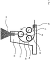
- Fig. 2 to 4 show schematic representations of a disposable cartridge 20 for a peristaltic micro pump provided with a housing 21.
- a channel section 22 of a fluid channel 23 is provided, the channel section 22 provided by a flexible tube 24.
- the disposable cartridge 20 comprises an inlet connector 25 and an outlet connector 26.
- the flexible tube 24, for pumping a fluid is to engage with a plurality of pump engaging elements 27 provided on a rotor 28.
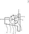
- FIG. 3 a schematic representation of another disposable cartridge 20 for a peristaltic micro pump is shown.
- a fluid reservoir 29 is connected to the inlet connector 25.
- the fluid reservoir 29 may be fixed to the housing 21, thereby, in some alternative embodiment substituting the inlet connector 25.
- the fluid reservoir 29 may be detachably connected to the inlet connector 25.
- the fluid reservoir 29 may be provided in the peristaltic micro pump itself, therefore, not being an element of the disposable cartridge 20.
- the plurality of pump engaging elements 27 provided on the rotor 28 is provided in a curved housing section 30.
- the flexible tube 24 comprises at least one sealing element 31 at the inlet and the outlet connectors 25, 26. Sealing elements provided on one end or both ends of the flexible tube 24 may be provided with double flange extensions (see Fig. 5 ).
- the inlet and / or the outlet connectors 25, 26 may be provided to couple with different connecting elements.
- the inlet connector 25 may be provided for coupling with a bayonet mount 25a containing a pipe or flexible tube.
- a flexible tube 25b may be fixed in the cartridge.
- a reservoir 25c may be attached detachably or fixed at inlet connector 25.
- Other elements 25d may be provided fixed at or to be connected with inlet connector 25.
- outlet connector 26 may be provided to couple with a bayonet mount 26a containing a pipe or flexible tube, may be fixed to a flexible tube 26b, or may be provided with other elements 26c fixed at the outlet connector 26 or connectable thereto.
- the other elements 25d, 26c may include, for example, valves.
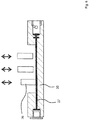
- FIG. 4 a schematic representation of a further disposable cartridge 20 for a peristaltic micro pump is shown.
- the flexible tube 24 itself provides for the inlet connector 25 and the outlet connector 26.
- the pump engaging elements 27 on the rotor 28 comprise three rollers. There may be more than three pump engaging elements 27 in an alternative embodiment.
- the disposable cartridge 20 comprises an integration of the flexible tube 24 and the inlet connector 25 and the outlet connector 26 instead of a tubing only.
- Fig. 5 shows a schematic representation of an assembly set of elements for a disposable cartridge for a peristaltic micro pump.
- the flexible tube 24 to be detachably received in the housing 21 comprises sealing elements 31, 32 on both ends, the sealing elements 31, 32 provided with flange extensions. In an alternative, there is only a single flange extension on the ends.
- the inlet connector 25 and the outlet connector 26 are disconnected and the whole disposable cartridge 20 with flexible tube 24, 33, 34 can be removed.
- the big advantage of this approach is the possibility to use different materials for tubing inside the pump and for the connected elements like pipes, as smaller peristaltic pumps use a single tube from reservoir through the pump to the outlet. Even rigid pipes of stainless steel or PTFE (polytetrafluorethylene) tubing can be connected to the disposable cartridge 20.
- Another advantage is the integration of the sealing elements 31, 32 at the ends of the flexible tubes 24, 33, 34, which improves connectivity.
- the flexible tube may be fixed in the housing during assembly and not be changed afterward.
- Sealing elements 31, 32 may be provided with double flange extensions 31a, 31b; 32a, 32b.
- a first, inner flange 31a, 32a serves to fix the flexible tube 24, 33, 34 and may also serve to prevent adhesives from spreading.
- Second, outer flange 31b, 32b then serves to seal the connection at connector 25, 26 and also to fix the tube in the housing 21.
- Flexible tube 34 may be provided with holding elements 34a, 34b.
- a holding element 34a may be provided without opening and is formed to be received by a corresponding cavity in housing 21 to prevent flexible tube 34 from moving or twisting when engaged by pump engaging elements.
- holding element 34b may be provided with an additional fluid canal.
- Fig. 6 shows a schematic representation of a linear pump element arrangement 35 comprising pump engaging elements 36 configured, for pumping, to engage with a linear channel section 37 of a fluid channel of a peristaltic micro pump, the linear channel section provided by a flexible tube.
- Fig. 7 is a schematic representation of an alternative linear pump element arrangement 35.
- pump element arrangement 36 is provided with engagement hooks 38 for coupling to a linear peristaltic micro pump.
- linear pump element arrangement 35 is shown with a plug connection on the left side and a bayonet mount on the right side.
- Fig. 8 shows a schematic representation of a disposable cartridge for a peristaltic micro pump provided with two channel sections 40, 41 of a fluid channel, the channel sections 40, 41 each provided by a flexible tube (micro fluidic mixing chip). It may be provided as a micro fluidic mixing chip (e.g. dimensions of 20 x 40 mm).
- the two channel sections 40, 41 provide for a curved tube section and a linear tube section configured to engage, through a respective opening in the housing, with the pump engaging elements providing a rotating pump element arrangement (see Fig. 2 to 4 ) and a linear pump element arrangement (see Figs. 6 and 7 ), respectively.
- Fig. 7 shows an embodiment with a linear flexible tube alignment geometry and a circular flexible tube alignment geometry, both approaches in one device for comparison.
- the linear actuator (pump engaging elements) operates the linear flexible tube section 40 from above through an opening 45 in the upper part of the chip housing.
- the rotor of the circular pump swings into another opening 46 of the chip housing to actuate the curved flexible tube section 40 of the fluid channel 47 provided in the housing.
- Suitable materials for the bodies of the housing of the disposable cartridge 20 are polymers that can be used in injection molding, e.g. poly(methyl methacrylate) (PMMA), cyclic olefin copolymer (COC), polycarbonate (PC). Another requirement is the possibility of a bonding step afterwards, thermally or by adhesives.
- the on chip versions can be additionally made of silicon and glass, resulting in different mechanical rigidity, chemical resistance and biocompatibility.
- Test bodies and structures for the disposable cartridge 20 were milled on a CNC milling machine (HEM 500, GF) with ball mills and end mills of 0.3 - 3.0 mm diameter. A batch of four test bodies was machined from one side on a plastic sheet. Then the single half bodies were separated. Different sample bodies were made of two different high tech PMMA (polymethyl-methacrylat) types with excellent homogeneity in structure and height (Hesaglas HL / VOS, TOPACRYL, Switzerland). Main difference between the polymers is their grade of cross linking, interesting for the bonding step of the two half shells.
- HEM 500, GF CNC milling machine
- PMMA polymethyl-methacrylat
- Main difference between the polymers is their grade of cross linking, interesting for the bonding step of the two half shells.
- the flexible tube was inserted into one side and the other side was added.
- the connection was secured by adhesives (Loctite 3301, Henkel and ACRIFIX 1R 0192, Evonik) or thermal bonding.
- the thread (M3) for the fluid connectors of the evaluation samples was implemented finally.
- Self-casted flexible tubes were made of the two component LSR silicone (liquid silicone rubber) QP1-70 (Dow Corning Corporation, Midland).
- the QP1 silicones are HTC-silicones (High Temperature Curing) that need 150 °C for curing ( Dow Corning, Product Information http://www2.dowcorning.com/Data Files/090007c8803 586b0.pdf, acquired 15.08.2012 ).
- For manual manufacturing refer to ( Loth et al., Key Engineering Materials, vol. 611-612, pp. 876-882, 2014 ).
- PTFE polytetrafluorethylene
- silicone silicone were chosen as tube materials for the connection or pipes.
- the tubes (0.8 mm x 1.6 mm, Bohlender), (1.02 mm x 2.16 mm, Silastic Lab Tubing, Dow Corning) were fixed with cyanoacrylate inside the fluid connectors.
- the micro rotor group consists of the main rotor part made of brass, three stainless steel pins 1 x 5 mm and rollers 2 x 2.95 mm. Brass and PEEK were used as roller materials.
- the arrangement prepared was used as key element to determine the characteristics of the peristaltic micro pump. It consists of the tube cartridge (not shown), the rotor with rollers, the a rotor clamping, a clutch to connect motor and rotor and a base plate.
- a pressure sensor (CTE 8025GY0, sensortechnics) different PTFE and silicone tubes with connectors, a high precision scale (AE 160, Mettler) were the testing periphery.
- a servo motor with encoder (1717T006S R IE2-16, Faulhaber) allows a maximum circumferential inlet speed of 5.000 rpm due to the 66:1 gear. The speed was adjusted via the motion controller (MCDC 3006S, Fauhaber).
- a LabVIEW program (National Instruments) was used for data acquisition and parameter control.
- the DAQ box was the NI 6009 (National Instruments).
- FIG. 9 The schematic setup for the tests is presented in Fig. 9 showing a schematic representation of a measurement setup.
- the different fluid ways for flow rate (I), pressure (II) and fatigue (III) experiments are marked with numbers and colored ways.
- test stage consisting of a fluid reservoir, the fluid connectors and the particular test stage was created.
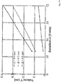
- the objective of the test was to investigate the dependency of the flow rate from inner tube diameter and circumferential speed.
- the circumferential speed was set between 24 and 72 rpm.
- Two fluids were tested partly with tubes of an inner diameter of 0.3 mm, 0.4 mm, 0.7 mm and 0.8 mm.
- the pump was started for 60 seconds at different circumferential speeds and the transported liquid has been collected and scaled. Every dosage step was repeated at least six times for higher accuracy.
- the weight was divided by the number of rotations and the number of rollers to obtain the single dosage volume.
- Mean variation is slightly higher for the lower values of 24 and 36 rpm.
- the coefficient of variation (COV) is between 1.02 and 4.8 percent for all speeds.
- the COV is lower for smaller inner diameters, possibly caused by lower fluctuations (Gilson, http: // www.seas.upenn.edu / ⁇ belab / equipment / equipment_links / Minipuls3_Manual.pdf, acquired 23.10.2015).
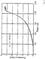
- the maximum pressure generated by the pump was carried out with the setup according to Fig. 8 (II). After activating the pump and closing the valve, the occurring pressure was measured. The circumferential speed was varied for different tests between 60 and 180 rpm.
- the test liquids were the previous used water and glycerin water mixture. The glycerin mixture was chosen due to the higher viscosity to reduce a possible backflow. Pump cartridges with the tube diameter of 0.7 mm have been used during the tests.
- Fig. 11 shows the diagram for the maximum pressure measurement. It is to be noted, that the time necessary to obtain that pressure was around 100 seconds due to the large dead volume after the pump. Several connectors, partly flexible pipes and the pressure sensor adapter reduced the dynamic of the pump.
- the fatigue behavior was investigated to identify the application spectrum of the micro pump.
- the test was carried out at a speed of 100 rpm.
- the cartridge was inserted into the bracket and connected with PTFE tubes.
- a fluid reservoir granted the circulation mode of the test liquid.
- the pressure sensor measured the adjacent pressure at the outlet of the pump.
- a pressure drop below a certain level, detected by the LabVIEW program would lead to a stop of the test.
- the set-up is shown in Fig. 8 (III).
- a modular micro fluidic peristaltic pump has been shown, where the complete contaminated disposable pump cartridge can be discarded after usage. Pipes, stiff PTFE tubes or other fluidic components can be easily connected via flexible ports and sealing ends. It provides the opportunity for a high pressure generation and a small single dosage volume in the nano liter range.
- the fatigue resistance of the tubes was high. Over eight hours of continuous operation will be more than enough for any LOC application. The real fatigue limit will be tested in future.
- the micro pump can be carried out as a stand-alone or an on chip device. Its small size suits to the requirements of low dead volume and high system integration.
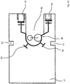
- Fig. 12 shows a schematic representation of an alternative disposable cartridge for a peristaltic micro pump provided with the channel section 40 of a fluid channel, the channel section 40 provided by a flexible tube. It may be provided as a micro fluidic mixing chip (e.g. dimensions of 20 x 40 mm).
- the channel section 40 provides for a curved tube section configured to engage, through a respective opening in the housing, with pump engaging elements providing a rotating pump element arrangement (see Fig. 2 to 4 ).
- the presented approach allows the simple integration of a tube and therefore a peristaltic micro pump into a ⁇ TAS device (TAS - Total Analysis System).
- Fig. 12 shows an embodiment with a circular flexible tube alignment geometry.
- the processed volume leaves the device through an outlet port 44.
- the rotor of the circular pump swings into an opening 46 of the housing 21 to actuate the curved flexible tube section of the fluid channel 40 provided in the housing 21.
- a linear flexible tube alignment geometry (see Figs. 6 and 7 ) may be provided.
- the linear actuator pump engaging elements
- each tube alignment geometry may be assigned to one inlet port 42, 43.
- Fig. 13 shows a schematic representation of an alternative embodiment of a disposable cartridge for a peristaltic micro pump provided with a channel section 40 of a fluid channel, the channel sections 40 provided by a flexible tube.
- the channel section 40 provides for a curved tube section configured to engage, through a respective opening in the housing, with the pump engaging elements providing a rotating pump element arrangement (see Fig. 2 to 4 ).
- This approach also allows the simple integration of a tube and therefore a peristaltic micro pump into a ⁇ TAS device (TAS - Total Analysis System).
- a wrap angle of the flexible tube is varied in comparison with the cartridges shown in Fig. 2 to 4 .
- the flexible tube is provided with holding elements 60 to prevent moving or twisting of the flexible tube when pump engaging elements are engaged.
- Recesses 61 are provided for coupling the cartridge to a peristaltic micro pump
Landscapes
- Engineering & Computer Science (AREA)
- Mechanical Engineering (AREA)
- General Engineering & Computer Science (AREA)
- Reciprocating Pumps (AREA)
Claims (12)
- Einwegkartusche (20) für eine peristaltische Mikropumpe, umfassend- ein Gehäuse (21);- einen Einlass, der an dem Gehäuse vorgesehen ist und einen Einlassanschluss (25) umfasst;- einen Auslass, der an dem Gehäuse vorgesehen ist und einen Auslassanschluss (26) umfasst;- einen Fluidkanal (23), der sich in dem Gehäuse (21) zwischen dem Einlass und dem Auslass erstreckt;- einen Kanalabschnitt (22) des Fluidkanals (23), wobei der Kanalabschnitt (22) durch ein flexibles Rohr (24; 33; 34) vorgesehen ist, das mindestens ein Dichtungselement (31, 32) an jedem von gegenüberliegenden Enden umfasst;- eine oder mehrere Öffnungen, die neben dem Kanalabschnitt (22) in dem Gehäuse (21) derart vorgesehen sind, dass eine oder mehrere Pumpeneingreifelemente eines Pumpenantriebs in das flexible Rohr (24; 33; 34) durch die Öffnung zum Komprimieren des flexiblen Rohrs (24; 33; 34) bei einem Pumpvorgang zum Pumpen eines Fluids durch den Fluidkanal (23) eingreifen können; und- eine Befestigungsvorrichtung, die an dem Gehäuse (21) vorgesehen ist, um das Gehäuse (21) in einem peristaltischen Mikropumpengehäuse entfernbar zu befestigen.
- Einwegkartusche (20) nach Anspruch 1, wobei das flexible Rohr (24; 33; 34) in einer Rohraussparung des Gehäuses (21) entfernbar aufgenommen ist.
- Einwegkartusche (20) nach Anspruch 1 oder 2, wobei das flexible Rohr (24; 33; 34) mindestens einen von einem gekrümmten Rohrabschnitt und einem linearen Rohrabschnitt umfasst, der konfiguriert ist, in das eine oder die mehreren Pumpeneingreifelemente einzugreifen, die eine rotierende Pumpenelementanordnung beziehungsweise eine lineare Pumpenelementanordnung bereitstellen.
- Einwegkartusche (20) nach Anspruch 3, wobei das Gehäuse (21) einen gekrümmten Gehäuseteil zum Aufnehmen von einem oder mehreren Eingreifelementen der rotierenden Pumpenelementanordnung (27) umfasst, die an einem Rotor (28) innerhalb des gekrümmten Gehäuseteils vorgesehen ist, wobei eine erste Öffnung neben dem gekrümmten Abschnitt in der Rotoraussparung vorgesehen ist.
- Einwegkartusche (20) nach Anspruch 4, wobei die erste Öffnung an einer schmalen Seite des Gehäuses (21) vorgesehen ist.
- Einwegkartusche (20) nach mindestens einem der Ansprüche 3 bis 5, wobei das Gehäuse (21) eine lineare Aussparung zum Aufnehmen des linearen Rohrabschnitts umfasst, wobei eine zweite Öffnung neben dem linearen Rohrabschnitt vorgesehen ist.
- Einwegkartusche (20) nach Anspruch 6, wobei die zweite Öffnung an einer flachen Seite des Gehäuses (21) vorgesehen ist.
- Einwegkartusche (20) nach mindestens einem der vorstehenden Ansprüche, wobei das flexible Rohr (24; 33; 34) mehrere flexible Unterrohre umfasst, wobei jedes von den flexiblen Unterrohren in einer separaten Unteraussparung des Gehäuses (21) aufgenommen ist und einen Kanalunterabschnitt des Fluidkanals bereitstellt.
- Einwegkartusche (20) nach mindestens einem der vorstehenden Ansprüche, wobei das flexible Rohr (24; 33; 34) formschlüssig in der Aussparung aufgenommen ist.
- Einwegkartusche (20) nach mindestens einem der vorstehenden Ansprüche, wobei das flexible Rohr (24; 33; 34) eine Flanscherweiterung in mindestens einem Endabschnitt umfasst.
- Einwegkartusche (20) nach mindestens einem der vorstehenden Ansprüche, ferner umfassend einen Flüssigkeitsvorratsbehälter (29), der in dem Gehäuse vorgesehen ist und eine Flüssigkeitsverbindung zu dem Fluidkanal (23) aufweist.
- Peristaltische Mikropumpe, die eine Einwegkartusche (20) nach mindestens einem der vorstehenden Ansprüche umfasst.
Applications Claiming Priority (1)
| Application Number | Priority Date | Filing Date | Title |
|---|---|---|---|
| DE102016004947 | 2016-04-15 |
Publications (2)
| Publication Number | Publication Date |
|---|---|
| EP3232060A1 EP3232060A1 (de) | 2017-10-18 |
| EP3232060B1 true EP3232060B1 (de) | 2019-03-13 |
Family
ID=58549015
Family Applications (1)
| Application Number | Title | Priority Date | Filing Date |
|---|---|---|---|
| EP17166526.8A Not-in-force EP3232060B1 (de) | 2016-04-15 | 2017-04-13 | Einwegpatrone für eine peristaltische mikropumpe und peristaltische mikropumpe |
Country Status (2)
| Country | Link |
|---|---|
| US (1) | US10774823B2 (de) |
| EP (1) | EP3232060B1 (de) |
Families Citing this family (3)
| Publication number | Priority date | Publication date | Assignee | Title |
|---|---|---|---|---|
| EP3823693B1 (de) * | 2018-07-17 | 2025-05-21 | Acist Medical Systems Inc. | Verbessertes injektionssystem und patientenset-anordnung dafür |
| JPWO2021166227A1 (de) * | 2020-02-21 | 2021-08-26 | ||
| CH717820A1 (de) * | 2020-09-08 | 2022-03-15 | Integra Biosciences Ag | Schlauch zum Anbringen an einer Dispensierkassette zur Aufnahme in einer Peristaltikpumpe. |
Citations (1)
| Publication number | Priority date | Publication date | Assignee | Title |
|---|---|---|---|---|
| JP5125811B2 (ja) * | 2008-06-30 | 2013-01-23 | セイコーエプソン株式会社 | チューブユニット、制御ユニット、及びこれらを備えるマイクロポンプ |
Family Cites Families (13)
| Publication number | Priority date | Publication date | Assignee | Title |
|---|---|---|---|---|
| USD264134S (en) * | 1979-05-07 | 1982-04-27 | Stewart-Reiss Laboratories, Inc. | Disposable cassette for use in a peristaltic pump |
| US4417856A (en) * | 1981-08-25 | 1983-11-29 | Minissian Kevin G | Peristaltic pump |
| US4735558A (en) * | 1986-04-08 | 1988-04-05 | Staar Surgical Company | Peristaltic pump latching mechanism |
| US4886431A (en) * | 1988-04-29 | 1989-12-12 | Cole-Parmer Instrument Company | Peristaltic pump having independently adjustable cartridges |
| DE19960668C1 (de) * | 1999-12-15 | 2001-08-16 | W O M Gmbh Physikalisch Medizi | Schlauchkasette für eine peristaltische Pumpe |
| JP3864695B2 (ja) * | 2000-11-09 | 2007-01-10 | 三浦工業株式会社 | 液体吐出装置 |
| CN100344874C (zh) * | 2003-01-28 | 2007-10-24 | 清华大学 | 一种流体的传输方法及实现该方法的微型蠕动泵 |
| US7001153B2 (en) * | 2003-06-30 | 2006-02-21 | Blue-White Industries | Peristaltic injector pump leak monitor |
| US8303275B2 (en) * | 2006-12-07 | 2012-11-06 | Seiko Epson Corporation | Micropump, tube unit, and control unit |
| US20090053085A1 (en) * | 2007-08-24 | 2009-02-26 | Thompson Loren M | Peristalitic pump assembly and method for attaching a cassette thereto |
| JP5282508B2 (ja) * | 2008-09-29 | 2013-09-04 | セイコーエプソン株式会社 | 制御ユニット、チューブユニット、マイクロポンプ |
| US9103340B2 (en) * | 2009-11-11 | 2015-08-11 | Swan Analytische Instrumente Ag | Peristaltic pump and hose cartridge therefor |
| US8459968B2 (en) * | 2011-09-19 | 2013-06-11 | Curlin Medical Inc. | Peristaltic pump cassette and method of installing same |
-
2017
- 2017-04-13 EP EP17166526.8A patent/EP3232060B1/de not_active Not-in-force
- 2017-04-13 US US15/486,676 patent/US10774823B2/en not_active Expired - Fee Related
Patent Citations (1)
| Publication number | Priority date | Publication date | Assignee | Title |
|---|---|---|---|---|
| JP5125811B2 (ja) * | 2008-06-30 | 2013-01-23 | セイコーエプソン株式会社 | チューブユニット、制御ユニット、及びこれらを備えるマイクロポンプ |
Also Published As
| Publication number | Publication date |
|---|---|
| EP3232060A1 (de) | 2017-10-18 |
| US10774823B2 (en) | 2020-09-15 |
| US20170298921A1 (en) | 2017-10-19 |
Similar Documents
| Publication | Publication Date | Title |
|---|---|---|
| Armani et al. | Re-configurable fluid circuits by PDMS elastomer micromachining | |
| CN107620804B (zh) | 流体控制装置 | |
| Skafte-Pedersen et al. | Multi-channel peristaltic pump for microfluidic applications featuring monolithic PDMS inlay | |
| CN103249486A (zh) | 微流体装置、微流体计量供给系统以及用于微流体测量和计量供给的方法 | |
| US10774823B2 (en) | Disposable cartridge for a peristaltic micro pump and a peristaltic micro pump | |
| EP1279832B1 (de) | Förderung von Fluiden durch einen Mikrokanal in einem elastischen Substrat durch regelmässiges Zusammendrücken von Teilen des Mikrokanals | |
| CN109311009B (zh) | 流体蠕动层泵 | |
| Darby et al. | A metering rotary nanopump for microfluidic systems | |
| EP3137214B1 (de) | Verfahren zur erzeugung von tröpfchen | |
| Loth et al. | Disposable high pressure peristaltic micro pump for standalone and on-chip applications | |
| Whulanza et al. | Design and characterization of finger-controlled micropump for lab-on-a-chip devices | |
| Sabourin et al. | Interconnection blocks: a method for providing reusable, rapid, multiple, aligned and planar microfluidic interconnections | |
| Atay et al. | Flow rate-controlled pipetting for microfluidics: second-generation flexible hydraulic reservoir (FHRv2) A. Atay et al. | |
| CN105736330A (zh) | 医用微量注射并联微泵 | |
| EP3431180A1 (de) | System zum laden und entladen von luft unter kontrolliertem druck | |
| Han et al. | Screw-actuated displacement micropumps for thermoplastic microfluidics | |
| Liu et al. | Arrayed pH-responsive microvalves controlled by multiphase laminar flow | |
| EP3377208B1 (de) | Flüssigkeitsmischvorrichtung und flüssigkeitsmischer dafür | |
| CN116529486B (zh) | 筒系统和单螺杆泵 | |
| Huang et al. | A microfluidic device for precise pipetting | |
| Loth et al. | Pneumatic actuated linear peristaltic micro pump for standalone and on-chip applications | |
| Rhie et al. | Design and fabrication of a screw-driven multi-channel peristaltic pump for portable microfluidic devices | |
| Loth et al. | Microfluidic high speed pinch valve | |
| WO2025172096A1 (en) | Microfluidic multi-channel rotary valve system | |
| Lam et al. | Digitally controllable large-scale integrated microfluidic systems |
Legal Events
| Date | Code | Title | Description |
|---|---|---|---|
| PUAI | Public reference made under article 153(3) epc to a published international application that has entered the european phase |
Free format text: ORIGINAL CODE: 0009012 |
|
| STAA | Information on the status of an ep patent application or granted ep patent |
Free format text: STATUS: THE APPLICATION HAS BEEN PUBLISHED |
|
| AK | Designated contracting states |
Kind code of ref document: A1 Designated state(s): AL AT BE BG CH CY CZ DE DK EE ES FI FR GB GR HR HU IE IS IT LI LT LU LV MC MK MT NL NO PL PT RO RS SE SI SK SM TR |
|
| AX | Request for extension of the european patent |
Extension state: BA ME |
|
| STAA | Information on the status of an ep patent application or granted ep patent |
Free format text: STATUS: REQUEST FOR EXAMINATION WAS MADE |
|
| 17P | Request for examination filed |
Effective date: 20180323 |
|
| RBV | Designated contracting states (corrected) |
Designated state(s): AL AT BE BG CH CY CZ DE DK EE ES FI FR GB GR HR HU IE IS IT LI LT LU LV MC MK MT NL NO PL PT RO RS SE SI SK SM TR |
|
| GRAP | Despatch of communication of intention to grant a patent |
Free format text: ORIGINAL CODE: EPIDOSNIGR1 |
|
| STAA | Information on the status of an ep patent application or granted ep patent |
Free format text: STATUS: GRANT OF PATENT IS INTENDED |
|
| GRAJ | Information related to disapproval of communication of intention to grant by the applicant or resumption of examination proceedings by the epo deleted |
Free format text: ORIGINAL CODE: EPIDOSDIGR1 |
|
| GRAP | Despatch of communication of intention to grant a patent |
Free format text: ORIGINAL CODE: EPIDOSNIGR1 |
|
| INTG | Intention to grant announced |
Effective date: 20180927 |
|
| INTG | Intention to grant announced |
Effective date: 20181018 |
|
| GRAS | Grant fee paid |
Free format text: ORIGINAL CODE: EPIDOSNIGR3 |
|
| GRAA | (expected) grant |
Free format text: ORIGINAL CODE: 0009210 |
|
| STAA | Information on the status of an ep patent application or granted ep patent |
Free format text: STATUS: THE PATENT HAS BEEN GRANTED |
|
| AK | Designated contracting states |
Kind code of ref document: B1 Designated state(s): AL AT BE BG CH CY CZ DE DK EE ES FI FR GB GR HR HU IE IS IT LI LT LU LV MC MK MT NL NO PL PT RO RS SE SI SK SM TR |
|
| REG | Reference to a national code |
Ref country code: GB Ref legal event code: FG4D |
|
| REG | Reference to a national code |
Ref country code: CH Ref legal event code: EP Ref country code: AT Ref legal event code: REF Ref document number: 1108060 Country of ref document: AT Kind code of ref document: T Effective date: 20190315 |
|
| REG | Reference to a national code |
Ref country code: IE Ref legal event code: FG4D |
|
| REG | Reference to a national code |
Ref country code: DE Ref legal event code: R096 Ref document number: 602017002622 Country of ref document: DE |
|
| REG | Reference to a national code |
Ref country code: NL Ref legal event code: MP Effective date: 20190313 |
|
| REG | Reference to a national code |
Ref country code: LT Ref legal event code: MG4D |
|
| PG25 | Lapsed in a contracting state [announced via postgrant information from national office to epo] |
Ref country code: FI Free format text: LAPSE BECAUSE OF FAILURE TO SUBMIT A TRANSLATION OF THE DESCRIPTION OR TO PAY THE FEE WITHIN THE PRESCRIBED TIME-LIMIT Effective date: 20190313 Ref country code: NO Free format text: LAPSE BECAUSE OF FAILURE TO SUBMIT A TRANSLATION OF THE DESCRIPTION OR TO PAY THE FEE WITHIN THE PRESCRIBED TIME-LIMIT Effective date: 20190613 Ref country code: SE Free format text: LAPSE BECAUSE OF FAILURE TO SUBMIT A TRANSLATION OF THE DESCRIPTION OR TO PAY THE FEE WITHIN THE PRESCRIBED TIME-LIMIT Effective date: 20190313 Ref country code: LT Free format text: LAPSE BECAUSE OF FAILURE TO SUBMIT A TRANSLATION OF THE DESCRIPTION OR TO PAY THE FEE WITHIN THE PRESCRIBED TIME-LIMIT Effective date: 20190313 |
|
| PG25 | Lapsed in a contracting state [announced via postgrant information from national office to epo] |
Ref country code: LV Free format text: LAPSE BECAUSE OF FAILURE TO SUBMIT A TRANSLATION OF THE DESCRIPTION OR TO PAY THE FEE WITHIN THE PRESCRIBED TIME-LIMIT Effective date: 20190313 Ref country code: RS Free format text: LAPSE BECAUSE OF FAILURE TO SUBMIT A TRANSLATION OF THE DESCRIPTION OR TO PAY THE FEE WITHIN THE PRESCRIBED TIME-LIMIT Effective date: 20190313 Ref country code: NL Free format text: LAPSE BECAUSE OF FAILURE TO SUBMIT A TRANSLATION OF THE DESCRIPTION OR TO PAY THE FEE WITHIN THE PRESCRIBED TIME-LIMIT Effective date: 20190313 Ref country code: GR Free format text: LAPSE BECAUSE OF FAILURE TO SUBMIT A TRANSLATION OF THE DESCRIPTION OR TO PAY THE FEE WITHIN THE PRESCRIBED TIME-LIMIT Effective date: 20190614 Ref country code: HR Free format text: LAPSE BECAUSE OF FAILURE TO SUBMIT A TRANSLATION OF THE DESCRIPTION OR TO PAY THE FEE WITHIN THE PRESCRIBED TIME-LIMIT Effective date: 20190313 Ref country code: BG Free format text: LAPSE BECAUSE OF FAILURE TO SUBMIT A TRANSLATION OF THE DESCRIPTION OR TO PAY THE FEE WITHIN THE PRESCRIBED TIME-LIMIT Effective date: 20190613 |
|
| REG | Reference to a national code |
Ref country code: AT Ref legal event code: MK05 Ref document number: 1108060 Country of ref document: AT Kind code of ref document: T Effective date: 20190313 |
|
| PG25 | Lapsed in a contracting state [announced via postgrant information from national office to epo] |
Ref country code: EE Free format text: LAPSE BECAUSE OF FAILURE TO SUBMIT A TRANSLATION OF THE DESCRIPTION OR TO PAY THE FEE WITHIN THE PRESCRIBED TIME-LIMIT Effective date: 20190313 Ref country code: ES Free format text: LAPSE BECAUSE OF FAILURE TO SUBMIT A TRANSLATION OF THE DESCRIPTION OR TO PAY THE FEE WITHIN THE PRESCRIBED TIME-LIMIT Effective date: 20190313 Ref country code: RO Free format text: LAPSE BECAUSE OF FAILURE TO SUBMIT A TRANSLATION OF THE DESCRIPTION OR TO PAY THE FEE WITHIN THE PRESCRIBED TIME-LIMIT Effective date: 20190313 Ref country code: CZ Free format text: LAPSE BECAUSE OF FAILURE TO SUBMIT A TRANSLATION OF THE DESCRIPTION OR TO PAY THE FEE WITHIN THE PRESCRIBED TIME-LIMIT Effective date: 20190313 Ref country code: IT Free format text: LAPSE BECAUSE OF FAILURE TO SUBMIT A TRANSLATION OF THE DESCRIPTION OR TO PAY THE FEE WITHIN THE PRESCRIBED TIME-LIMIT Effective date: 20190313 Ref country code: PT Free format text: LAPSE BECAUSE OF FAILURE TO SUBMIT A TRANSLATION OF THE DESCRIPTION OR TO PAY THE FEE WITHIN THE PRESCRIBED TIME-LIMIT Effective date: 20190713 Ref country code: SK Free format text: LAPSE BECAUSE OF FAILURE TO SUBMIT A TRANSLATION OF THE DESCRIPTION OR TO PAY THE FEE WITHIN THE PRESCRIBED TIME-LIMIT Effective date: 20190313 Ref country code: AL Free format text: LAPSE BECAUSE OF FAILURE TO SUBMIT A TRANSLATION OF THE DESCRIPTION OR TO PAY THE FEE WITHIN THE PRESCRIBED TIME-LIMIT Effective date: 20190313 |
|
| PG25 | Lapsed in a contracting state [announced via postgrant information from national office to epo] |
Ref country code: PL Free format text: LAPSE BECAUSE OF FAILURE TO SUBMIT A TRANSLATION OF THE DESCRIPTION OR TO PAY THE FEE WITHIN THE PRESCRIBED TIME-LIMIT Effective date: 20190313 Ref country code: SM Free format text: LAPSE BECAUSE OF FAILURE TO SUBMIT A TRANSLATION OF THE DESCRIPTION OR TO PAY THE FEE WITHIN THE PRESCRIBED TIME-LIMIT Effective date: 20190313 |
|
| REG | Reference to a national code |
Ref country code: DE Ref legal event code: R097 Ref document number: 602017002622 Country of ref document: DE |
|
| REG | Reference to a national code |
Ref country code: BE Ref legal event code: MM Effective date: 20190430 |
|
| PG25 | Lapsed in a contracting state [announced via postgrant information from national office to epo] |
Ref country code: LU Free format text: LAPSE BECAUSE OF NON-PAYMENT OF DUE FEES Effective date: 20190413 Ref country code: AT Free format text: LAPSE BECAUSE OF FAILURE TO SUBMIT A TRANSLATION OF THE DESCRIPTION OR TO PAY THE FEE WITHIN THE PRESCRIBED TIME-LIMIT Effective date: 20190313 Ref country code: IS Free format text: LAPSE BECAUSE OF FAILURE TO SUBMIT A TRANSLATION OF THE DESCRIPTION OR TO PAY THE FEE WITHIN THE PRESCRIBED TIME-LIMIT Effective date: 20190713 |
|
| PLBE | No opposition filed within time limit |
Free format text: ORIGINAL CODE: 0009261 |
|
| STAA | Information on the status of an ep patent application or granted ep patent |
Free format text: STATUS: NO OPPOSITION FILED WITHIN TIME LIMIT |
|
| PG25 | Lapsed in a contracting state [announced via postgrant information from national office to epo] |
Ref country code: MC Free format text: LAPSE BECAUSE OF FAILURE TO SUBMIT A TRANSLATION OF THE DESCRIPTION OR TO PAY THE FEE WITHIN THE PRESCRIBED TIME-LIMIT Effective date: 20190313 Ref country code: DK Free format text: LAPSE BECAUSE OF FAILURE TO SUBMIT A TRANSLATION OF THE DESCRIPTION OR TO PAY THE FEE WITHIN THE PRESCRIBED TIME-LIMIT Effective date: 20190313 |
|
| 26N | No opposition filed |
Effective date: 20191216 |
|
| PG25 | Lapsed in a contracting state [announced via postgrant information from national office to epo] |
Ref country code: SI Free format text: LAPSE BECAUSE OF FAILURE TO SUBMIT A TRANSLATION OF THE DESCRIPTION OR TO PAY THE FEE WITHIN THE PRESCRIBED TIME-LIMIT Effective date: 20190313 Ref country code: BE Free format text: LAPSE BECAUSE OF NON-PAYMENT OF DUE FEES Effective date: 20190430 |
|
| PG25 | Lapsed in a contracting state [announced via postgrant information from national office to epo] |
Ref country code: TR Free format text: LAPSE BECAUSE OF FAILURE TO SUBMIT A TRANSLATION OF THE DESCRIPTION OR TO PAY THE FEE WITHIN THE PRESCRIBED TIME-LIMIT Effective date: 20190313 |
|
| PG25 | Lapsed in a contracting state [announced via postgrant information from national office to epo] |
Ref country code: IE Free format text: LAPSE BECAUSE OF NON-PAYMENT OF DUE FEES Effective date: 20190413 |
|
| PG25 | Lapsed in a contracting state [announced via postgrant information from national office to epo] |
Ref country code: CY Free format text: LAPSE BECAUSE OF FAILURE TO SUBMIT A TRANSLATION OF THE DESCRIPTION OR TO PAY THE FEE WITHIN THE PRESCRIBED TIME-LIMIT Effective date: 20190313 |
|
| PG25 | Lapsed in a contracting state [announced via postgrant information from national office to epo] |
Ref country code: MT Free format text: LAPSE BECAUSE OF FAILURE TO SUBMIT A TRANSLATION OF THE DESCRIPTION OR TO PAY THE FEE WITHIN THE PRESCRIBED TIME-LIMIT Effective date: 20190313 Ref country code: HU Free format text: LAPSE BECAUSE OF FAILURE TO SUBMIT A TRANSLATION OF THE DESCRIPTION OR TO PAY THE FEE WITHIN THE PRESCRIBED TIME-LIMIT; INVALID AB INITIO Effective date: 20170413 |
|
| PG25 | Lapsed in a contracting state [announced via postgrant information from national office to epo] |
Ref country code: MK Free format text: LAPSE BECAUSE OF FAILURE TO SUBMIT A TRANSLATION OF THE DESCRIPTION OR TO PAY THE FEE WITHIN THE PRESCRIBED TIME-LIMIT Effective date: 20190313 |
|
| PGFP | Annual fee paid to national office [announced via postgrant information from national office to epo] |
Ref country code: GB Payment date: 20220425 Year of fee payment: 6 Ref country code: FR Payment date: 20220420 Year of fee payment: 6 Ref country code: DE Payment date: 20220419 Year of fee payment: 6 |
|
| PGFP | Annual fee paid to national office [announced via postgrant information from national office to epo] |
Ref country code: CH Payment date: 20220421 Year of fee payment: 6 |
|
| REG | Reference to a national code |
Ref country code: DE Ref legal event code: R119 Ref document number: 602017002622 Country of ref document: DE |
|
| REG | Reference to a national code |
Ref country code: CH Ref legal event code: PL |
|
| GBPC | Gb: european patent ceased through non-payment of renewal fee |
Effective date: 20230413 |
|
| PG25 | Lapsed in a contracting state [announced via postgrant information from national office to epo] |
Ref country code: GB Free format text: LAPSE BECAUSE OF NON-PAYMENT OF DUE FEES Effective date: 20230413 |
|
| PG25 | Lapsed in a contracting state [announced via postgrant information from national office to epo] |
Ref country code: LI Free format text: LAPSE BECAUSE OF NON-PAYMENT OF DUE FEES Effective date: 20230430 Ref country code: GB Free format text: LAPSE BECAUSE OF NON-PAYMENT OF DUE FEES Effective date: 20230413 Ref country code: FR Free format text: LAPSE BECAUSE OF NON-PAYMENT OF DUE FEES Effective date: 20230430 Ref country code: DE Free format text: LAPSE BECAUSE OF NON-PAYMENT OF DUE FEES Effective date: 20231103 Ref country code: CH Free format text: LAPSE BECAUSE OF NON-PAYMENT OF DUE FEES Effective date: 20230430 |