EP3232067A1 - Anneau ou rangée annulaire d'un moteur à turbine à gaz, ensemble et procédé de conception associés - Google Patents
Anneau ou rangée annulaire d'un moteur à turbine à gaz, ensemble et procédé de conception associés Download PDFInfo
- Publication number
- EP3232067A1 EP3232067A1 EP17159392.4A EP17159392A EP3232067A1 EP 3232067 A1 EP3232067 A1 EP 3232067A1 EP 17159392 A EP17159392 A EP 17159392A EP 3232067 A1 EP3232067 A1 EP 3232067A1
- Authority
- EP
- European Patent Office
- Prior art keywords
- spacing
- vanes
- gas turbine
- turbine engine
- circular row
- Prior art date
- Legal status (The legal status is an assumption and is not a legal conclusion. Google has not performed a legal analysis and makes no representation as to the accuracy of the status listed.)
- Withdrawn
Links
- 238000000034 method Methods 0.000 title claims abstract description 15
- 239000007789 gas Substances 0.000 description 45
- 230000000712 assembly Effects 0.000 description 2
- 238000000429 assembly Methods 0.000 description 2
- 238000012986 modification Methods 0.000 description 2
- 230000004048 modification Effects 0.000 description 2
- 230000005284 excitation Effects 0.000 description 1
- 239000012530 fluid Substances 0.000 description 1
- 238000004519 manufacturing process Methods 0.000 description 1
- 230000003068 static effect Effects 0.000 description 1
- 238000011144 upstream manufacturing Methods 0.000 description 1
Images



Classifications
-
- F—MECHANICAL ENGINEERING; LIGHTING; HEATING; WEAPONS; BLASTING
- F04—POSITIVE - DISPLACEMENT MACHINES FOR LIQUIDS; PUMPS FOR LIQUIDS OR ELASTIC FLUIDS
- F04D—NON-POSITIVE-DISPLACEMENT PUMPS
- F04D29/00—Details, component parts, or accessories
- F04D29/66—Combating cavitation, whirls, noise, vibration or the like; Balancing
- F04D29/661—Combating cavitation, whirls, noise, vibration or the like; Balancing especially adapted for elastic fluid pumps
- F04D29/666—Combating cavitation, whirls, noise, vibration or the like; Balancing especially adapted for elastic fluid pumps by means of rotor construction or layout, e.g. unequal distribution of blades or vanes
-
- F—MECHANICAL ENGINEERING; LIGHTING; HEATING; WEAPONS; BLASTING
- F01—MACHINES OR ENGINES IN GENERAL; ENGINE PLANTS IN GENERAL; STEAM ENGINES
- F01D—NON-POSITIVE DISPLACEMENT MACHINES OR ENGINES, e.g. STEAM TURBINES
- F01D9/00—Stators
- F01D9/02—Nozzles; Nozzle boxes; Stator blades; Guide conduits, e.g. individual nozzles
- F01D9/04—Nozzles; Nozzle boxes; Stator blades; Guide conduits, e.g. individual nozzles forming ring or sector
- F01D9/041—Nozzles; Nozzle boxes; Stator blades; Guide conduits, e.g. individual nozzles forming ring or sector using blades
-
- F—MECHANICAL ENGINEERING; LIGHTING; HEATING; WEAPONS; BLASTING
- F01—MACHINES OR ENGINES IN GENERAL; ENGINE PLANTS IN GENERAL; STEAM ENGINES
- F01D—NON-POSITIVE DISPLACEMENT MACHINES OR ENGINES, e.g. STEAM TURBINES
- F01D9/00—Stators
- F01D9/02—Nozzles; Nozzle boxes; Stator blades; Guide conduits, e.g. individual nozzles
- F01D9/04—Nozzles; Nozzle boxes; Stator blades; Guide conduits, e.g. individual nozzles forming ring or sector
- F01D9/042—Nozzles; Nozzle boxes; Stator blades; Guide conduits, e.g. individual nozzles forming ring or sector fixing blades to stators
-
- F—MECHANICAL ENGINEERING; LIGHTING; HEATING; WEAPONS; BLASTING
- F04—POSITIVE - DISPLACEMENT MACHINES FOR LIQUIDS; PUMPS FOR LIQUIDS OR ELASTIC FLUIDS
- F04D—NON-POSITIVE-DISPLACEMENT PUMPS
- F04D29/00—Details, component parts, or accessories
- F04D29/40—Casings; Connections of working fluid
- F04D29/52—Casings; Connections of working fluid for axial pumps
- F04D29/54—Fluid-guiding means, e.g. diffusers
- F04D29/541—Specially adapted for elastic fluid pumps
- F04D29/542—Bladed diffusers
-
- F—MECHANICAL ENGINEERING; LIGHTING; HEATING; WEAPONS; BLASTING
- F04—POSITIVE - DISPLACEMENT MACHINES FOR LIQUIDS; PUMPS FOR LIQUIDS OR ELASTIC FLUIDS
- F04D—NON-POSITIVE-DISPLACEMENT PUMPS
- F04D29/00—Details, component parts, or accessories
- F04D29/26—Rotors specially for elastic fluids
- F04D29/32—Rotors specially for elastic fluids for axial flow pumps
- F04D29/325—Rotors specially for elastic fluids for axial flow pumps for axial flow fans
- F04D29/328—Rotors specially for elastic fluids for axial flow pumps for axial flow fans with unequal distribution of blades around the hub
-
- F—MECHANICAL ENGINEERING; LIGHTING; HEATING; WEAPONS; BLASTING
- F05—INDEXING SCHEMES RELATING TO ENGINES OR PUMPS IN VARIOUS SUBCLASSES OF CLASSES F01-F04
- F05D—INDEXING SCHEME FOR ASPECTS RELATING TO NON-POSITIVE-DISPLACEMENT MACHINES OR ENGINES, GAS-TURBINES OR JET-PROPULSION PLANTS
- F05D2220/00—Application
- F05D2220/30—Application in turbines
- F05D2220/32—Application in turbines in gas turbines
-
- F—MECHANICAL ENGINEERING; LIGHTING; HEATING; WEAPONS; BLASTING
- F05—INDEXING SCHEMES RELATING TO ENGINES OR PUMPS IN VARIOUS SUBCLASSES OF CLASSES F01-F04
- F05D—INDEXING SCHEME FOR ASPECTS RELATING TO NON-POSITIVE-DISPLACEMENT MACHINES OR ENGINES, GAS-TURBINES OR JET-PROPULSION PLANTS
- F05D2240/00—Components
- F05D2240/10—Stators
- F05D2240/12—Fluid guiding means, e.g. vanes
-
- F—MECHANICAL ENGINEERING; LIGHTING; HEATING; WEAPONS; BLASTING
- F05—INDEXING SCHEMES RELATING TO ENGINES OR PUMPS IN VARIOUS SUBCLASSES OF CLASSES F01-F04
- F05D—INDEXING SCHEME FOR ASPECTS RELATING TO NON-POSITIVE-DISPLACEMENT MACHINES OR ENGINES, GAS-TURBINES OR JET-PROPULSION PLANTS
- F05D2240/00—Components
- F05D2240/10—Stators
- F05D2240/12—Fluid guiding means, e.g. vanes
- F05D2240/128—Nozzles
-
- F—MECHANICAL ENGINEERING; LIGHTING; HEATING; WEAPONS; BLASTING
- F05—INDEXING SCHEMES RELATING TO ENGINES OR PUMPS IN VARIOUS SUBCLASSES OF CLASSES F01-F04
- F05D—INDEXING SCHEME FOR ASPECTS RELATING TO NON-POSITIVE-DISPLACEMENT MACHINES OR ENGINES, GAS-TURBINES OR JET-PROPULSION PLANTS
- F05D2250/00—Geometry
- F05D2250/30—Arrangement of components
-
- F—MECHANICAL ENGINEERING; LIGHTING; HEATING; WEAPONS; BLASTING
- F05—INDEXING SCHEMES RELATING TO ENGINES OR PUMPS IN VARIOUS SUBCLASSES OF CLASSES F01-F04
- F05D—INDEXING SCHEME FOR ASPECTS RELATING TO NON-POSITIVE-DISPLACEMENT MACHINES OR ENGINES, GAS-TURBINES OR JET-PROPULSION PLANTS
- F05D2260/00—Function
- F05D2260/96—Preventing, counteracting or reducing vibration or noise
- F05D2260/961—Preventing, counteracting or reducing vibration or noise by mistuning rotor blades or stator vanes with irregular interblade spacing, airfoil shape
Definitions
- This invention relates generally to aircraft gas turbine engine stator vanes and, particularly, to non-uniform vane spacing.
- Stator vanes are commonly used in aircraft gas turbine engine compressors and fans and in some turbine designs.
- Non-rotating or stationary stator vanes typically are placed downstream or upstream of rotor blades of the fans, compressors, and turbines. These vanes influence the tangential flow component entering or leaving the rotors, may increase the static pressure of the fluid and may set the flow angle to a level appropriate for the downstream rotor.
- Non-rotating stationary stator vanes may be variable stator vanes capable of having their angle varied or may be fixed and not able to vary their angle with respect to the incoming gas flow.
- Airfoils in vanes have a series of excitation frequencies associated with them. More specifically, each airfoil produces a wake in an air stream that is felt as a pulse by a passing airfoil.
- the combination of the number of stator vane wakes (pulses) and the rotational speed of the compressor creates a stimulus that may coincide with a natural frequency of the rotor blades. It is highly desirable to keep the majority of the airfoil natural frequencies outside of the designed engine operating range.
- NUVS Non-uniform vane spacing
- NUVS designs have been developed to reduce induced rotor blade vibrations.
- NUVS designs vary the vane spacing around the circumference of the engine casing to facilitate avoidance of rotor blade and stator vane natural frequencies or to reduce the amplitude of rotor blade resonant response at these frequencies. More specifically, within such designs the number of stator vanes is varied in one or more sectors of the stator vane assembly. Although the stator vane spacing may vary from one sector to the next, the stator vanes within each sector remain equally spaced relative to each other, and/or are designed with an equal pitch. The variation in vane spacing or pitch between stator vane sectors facilitates changing the frequency of the vane wakes to reduce the vibration response induced in adjacent rotor blades.
- Some conventional non-uniform vane spacing designs can cause compressor performance and operability issues.
- Some conventional non-uniform vane spacing designs can require a large number of vane sector configurations with associated manufacturing and inventory costs.
- a gas turbine engine ring or circular row of non-uniformally spaced vanes includes first group and second groups including all the vanes in the ring or circular row, only one first group and only one second group of adjacent vanes, unequal first and second spacing between the adjacent vanes in the first and second groups respectively, and the first spacing greater than the second spacing.
- the second group may include only three adjacent vanes and only two adjacent pairs of the vanes and the second spacing between each of the vanes in each of the two adjacent pairs.
- a nominal uniform spacing of the stator vanes may be used as a design parameter for designing the spacing of the non-uniformly spaced stator vanes and the second spacing may be about 25%-35% smaller than the nominal uniform spacing.
- the gas turbine engine ring or circular row may be sectored.
- the gas turbine engine ring or circular row may include about 9 to 14 sectors and about 8 to 16 vanes per sector.
- the second group may include two or more adjacent vanes including one or more adjacent pairs of the vanes and the second spacing being between each of the one or more adjacent pairs of the vanes respectively.
- a gas turbine engine assembly may include a gas turbine engine section including one or more rings or circular rows of fixed and/or variable non-uniformally spaced vanes, first group and second groups including all the vanes in each of the one or more rings or circular rows, only one first group and only one second group of adjacent vanes in each of the one or more rings or circular rows, unequal first and second spacing between the adjacent vanes in the first and second groups respectively, and the first spacing greater than the second spacing.
- a method for designing non-uniform vane spacing for a ring or circular row of non-uniformally spaced gas turbine engine vanes includes determining a 360 degree nominal uniform spacing S pattern, spreading apart one interim pair of the nominal uniformally spaced apart vanes and moving the remaining vanes closer together wherein the remaining vanes are all evenly spaced at a first spacing creating one big gap or an interim large spacing between the interim pair, and inserting an additional vane in the one big gap or interim large spacing forming two adjacent equal narrow gaps or spaces having second spacings smaller than the first spacing.
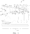
- FIG. 1 Illustrated in FIG. 1 is an exemplary gas turbine engine high pressure compressor 18 with at least one ring or circular row 11 of stator vanes 15 with non-uniform vane spacing (NUVS) illustrated in FIG. 2 .
- a circular ring or row 13 of inlet variable stator vanes 16 which may have non-uniform vane spacing (NUVS) are also illustrated as being disposed in the compressor 18 and are used to optimize the direction at which gases flowing downstream D through a compressor flowpath 20 of the compressor 18 enter first and second rows 47, 48 of rotatable blades 50.
- the circular rows 11 of the fixed or variable stator vanes 15 are axisymmetrical about a longitudinal or axial centerline axis 12.
- the high pressure compressor 18 is generally axisymmetrical about the longitudinal or axial centerline axis 12.
- a circular ring or row 13 of inlet variable stator vanes 16 which may have non-uniform vane spacing (NUVS) are disposed in the compressor 18 and used to optimize the direction at which gases flowing downstream D through the compressor 18 enter the first and second rows 47, 48 of rotatable blades 50.
- NUVS non-uniform vane spacing
- the exemplary embodiment of the stator vanes 15 with non-uniform vane spacing disclosed herein is for a high pressure compressor 18, similar stator vanes 15 with non-uniform vane spacing disclosed herein may be used in other compressor sections and in fan and turbine sections of a gas turbine engine as well.
- a compressor casing 61 radially outwardly supports stator vane assemblies 56 which include the stator vanes 15.
- At least one stator vane assembly 56 or circular row 11 of stator vanes 15 includes a plurality of stator vanes 15.
- Each stator vane 15 has an airfoil 31 radially disposed between the casing 61 and an inner ring 81 which is spaced radially inwardly of the casing 61.
- the airfoil 31 extends inwardly from an airfoil outer end 72 to an airfoil inner end 73 along a span SP of the airfoil.
- the stator vanes may be or variable, capable of having their angle varied as illustrated in FIG. 1 .
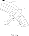
- At least one of the variable stator vane assemblies 56 or circular rows 11 of stator vanes 15 include non-uniform vane spacing indicated by unequal first and second spacing S1, S2 between the vanes 15 in first and second groups G1, G2 respectively of the vanes 15, as illustrated in FIGS. 2 and 2A .
- the exemplary first spacing S1 is greater than the exemplary second spacing S2.
- the unequal first and second spacing S1, S2 are circular or linear distances between the vanes 15. Adjacent vanes 15 in the first and second groups G1, G2 have the same first and second spacing S1, S2 respectively between them.
- S1, S2 may be measured circumferentially along an arc C between an adjacent pair 17 of the vanes 15.
- the arc C extends between a pair of adjacent radii R having a common origin 19 on the axial centerline axis 12 and pass through the adjacent pair 17 of the vanes 15 respectively.
- S1, S2 may be measured linearly from the intersections I of the arc C and the adjacent pair 17 of adjacent radii R having the common origin 19 on the axial centerline axis 12.
- the non-uniform vane spacing may also be angular and measured in degrees between the vanes 15.
- the non-uniform vane spacing may be indicated by unequal first and second angles A1, A2 as measured between the vanes 15 in the first and second groups G1, G2 respectively of the vanes 15 as illustrated in FIG. 2 .
- the radii R may be along centerlines L of the vanes 15 and the unequal first and second angles A1, A2 may be measured between these adjacent radii R.
- the exemplary embodiment of the non-uniform vane spacing illustrated herein in the circular row 11 of non-uniformly spaced stator vanes 15 includes only a single first group G1 and only a single second group G2.
- One of the groups includes widely spaced stator vanes 15 and the other group includes narrowly spaced stator vanes 15.
- the embodiment of the circular row 11 of non-uniformly spaced stator vanes 15, illustrated in FIG. 2 illustrates the single first group G1 as including the widely spaced vanes 15.
- FIG. 2 also illustrates the single second group G2 as including the narrowly spaced apart vanes 15. Only three narrowly spaced vanes 15 spaced narrowly apart with the second spacing S2 between the vanes 15.
- FIG. 6 Other embodiments may have only two narrowly spaced apart vanes 15 with a second spacing S2 between them as illustrated in FIG. 6 .
- the circular row 11 of non-uniformly spaced stator vanes 15 includes a second group G2 of two or more narrowly spaced apart vanes 15 having a second small or narrow spacing S2 therebetween.
- one method may start with a 360 degree equal or uniform spacing S pattern as illustrated in FIG. 3 .
- the uniform spacing S is a nominal spacing which is a design parameter used in designing the spacing of the non-uniformly spaced stator vanes 15.
- FIG. 4 illustrates a subsequent step in the design method in which an interim pair 24 of the spaced apart vanes 15 illustrated in FIG. 3 are spread apart and the remaining vanes 26 are all evenly spaced closer together at what is the first spacing S1, illustrated in FIG. 2 , thus, creating one big gap 33 or with an interim large spacing S3 between the interim pair 24 of the spaced apart vanes 15.
- the first spacing S1 is somewhat smaller than the nominal or uniform spacing S.
- the second spacing S2 is substantially smaller than the nominal or uniform spacing S and in the embodiment illustrated herein the second spacing S2 is about 65%-75% of the nominal or uniform spacing S. Put another way the second spacing S2 is about 25%-35% smaller than the nominal or uniform spacing S.
- the ring or circular row 11 of stator vanes 15 with non-uniform vane spacing may be sectored as illustrated by first and second sectors 36, 38 separated by splits 40 as illustrated in FIG. 5 .
- the sectored embodiment of the row of non-uniformly spaced stator vanes illustrated in FIG. 5 may include several sectors and several vanes 15 in each sector.
- the exemplary embodiment illustrated herein includes 9 to 14 sectors per gas turbine engine compressor stage and about 8-16 vanes per sector.
Landscapes
- Engineering & Computer Science (AREA)
- Mechanical Engineering (AREA)
- General Engineering & Computer Science (AREA)
- Turbine Rotor Nozzle Sealing (AREA)
- Structures Of Non-Positive Displacement Pumps (AREA)
Applications Claiming Priority (1)
| Application Number | Priority Date | Filing Date | Title |
|---|---|---|---|
| US15/070,418 US10443626B2 (en) | 2016-03-15 | 2016-03-15 | Non uniform vane spacing |
Publications (1)
| Publication Number | Publication Date |
|---|---|
| EP3232067A1 true EP3232067A1 (fr) | 2017-10-18 |
Family
ID=58231523
Family Applications (1)
| Application Number | Title | Priority Date | Filing Date |
|---|---|---|---|
| EP17159392.4A Withdrawn EP3232067A1 (fr) | 2016-03-15 | 2017-03-06 | Anneau ou rangée annulaire d'un moteur à turbine à gaz, ensemble et procédé de conception associés |
Country Status (5)
| Country | Link |
|---|---|
| US (1) | US10443626B2 (fr) |
| EP (1) | EP3232067A1 (fr) |
| JP (1) | JP2017166482A (fr) |
| CN (1) | CN107191231B (fr) |
| CA (1) | CA2959676A1 (fr) |
Families Citing this family (21)
| Publication number | Priority date | Publication date | Assignee | Title |
|---|---|---|---|---|
| US10378554B2 (en) * | 2014-09-23 | 2019-08-13 | Pratt & Whitney Canada Corp. | Gas turbine engine with partial inlet vane |
| US10526905B2 (en) * | 2017-03-29 | 2020-01-07 | United Technologies Corporation | Asymmetric vane assembly |
| CN109114019A (zh) * | 2017-06-23 | 2019-01-01 | 博格华纳公司 | 轴向风扇 |
| CN108194424B (zh) * | 2017-11-22 | 2020-05-08 | 中国北方发动机研究所(天津) | 一种基于压气机蜗壳非对称性的叶片式机匣处理装置 |
| US10889366B2 (en) * | 2018-09-21 | 2021-01-12 | Textron Innovations Inc. | Ducted thrusters |
| US11952943B2 (en) | 2019-12-06 | 2024-04-09 | Pratt & Whitney Canada Corp. | Assembly for a compressor section of a gas turbine engine |
| US20220100919A1 (en) * | 2020-09-30 | 2022-03-31 | General Electric Company | Probabilistic fatigue and blend limit assessment and visualization methods for airfoils |
| US11827344B2 (en) * | 2020-12-09 | 2023-11-28 | Textron Innovations Inc. | Low noise ducted fan |
| US11512611B2 (en) * | 2021-02-09 | 2022-11-29 | General Electric Company | Stator apparatus for a gas turbine engine |
| CN116557346A (zh) * | 2022-02-07 | 2023-08-08 | 通用电气公司 | 具有不同定向级的翼型件组件 |
| CN114893442B (zh) * | 2022-05-09 | 2023-05-23 | 北京航空航天大学 | 一种导叶、压气机及压气机的气动布局设计方法 |
| FR3138469B1 (fr) * | 2022-07-29 | 2025-12-05 | Safran Aircraft Engines | Carter fixe d’une turbomachine dont les bras sont non équirépartis |
| CN115306487B (zh) * | 2022-08-05 | 2025-08-29 | 中国航发贵阳发动机设计研究所 | 一种适用于高压涡轮转子叶片减振的非对称导叶设计方法 |
| US12018592B1 (en) | 2022-12-21 | 2024-06-25 | General Electric Company | Outlet guide vane assembly for a turbofan engine |
| US12376660B2 (en) * | 2023-01-17 | 2025-08-05 | Sharkninja Operating Llc | Hot brush |
| CN116163813B (zh) * | 2023-04-04 | 2025-12-26 | 中国航发湖南动力机械研究所 | 一种涡轮导向器及涡轮发动机 |
| US12410722B2 (en) | 2023-06-15 | 2025-09-09 | General Electric Company | Circumferential row of vanes for a gas turbine engine and having non-uniform vane spacing |
| US12320304B2 (en) | 2023-08-18 | 2025-06-03 | General Electric Company | Gas turbine engine including a compressor bleed air system |
| US12366176B2 (en) | 2023-08-28 | 2025-07-22 | General Electric Company | Rotor system for a turbine engine |
| US20250215840A1 (en) * | 2023-12-29 | 2025-07-03 | Rtx Corporation | Aircraft propulsion system with asymmetric exhaust assembly |
| US12497905B1 (en) * | 2024-06-12 | 2025-12-16 | Rtx Corporation | Non-uniform and bi-tri stator spacing for swirl recovery vane (SRV) open rotor engines |
Citations (3)
| Publication number | Priority date | Publication date | Assignee | Title |
|---|---|---|---|---|
| GB1058759A (en) * | 1963-12-24 | 1967-02-15 | Ass Elect Ind | Improvements in or relating to the bladed diaphragms of turbines |
| EP2602490A2 (fr) * | 2011-12-07 | 2013-06-12 | Rolls-Royce plc | Rangée d'aubes de stator |
| WO2015056455A1 (fr) * | 2013-10-17 | 2015-04-23 | 三菱重工業株式会社 | Compresseur et turbine à gaz |
Family Cites Families (18)
| Publication number | Priority date | Publication date | Assignee | Title |
|---|---|---|---|---|
| US1058759A (en) * | 1913-02-05 | 1913-04-15 | Henry Kershaw | Mail-bag catching and delivering apparatus. |
| US1534721A (en) * | 1924-04-28 | 1925-04-21 | Aeg | Construction of elastic-fluid turbines to prevent breakage of blades due to vibrations |
| US3006603A (en) * | 1954-08-25 | 1961-10-31 | Gen Electric | Turbo-machine blade spacing with modulated pitch |
| US3347520A (en) * | 1966-07-12 | 1967-10-17 | Jerzy A Oweczarek | Turbomachine blading |
| CH470588A (de) * | 1968-01-22 | 1969-03-31 | Bbc Brown Boveri & Cie | Geräuschminderung bei aerodynamischen Druckwellenmaschinen |
| US4084922A (en) * | 1976-12-27 | 1978-04-18 | Electric Power Research Institute, Inc. | Turbine rotor with pin mounted ceramic turbine blades |
| US5681145A (en) | 1996-10-30 | 1997-10-28 | Itt Automotive Electrical Systems, Inc. | Low-noise, high-efficiency fan assembly combining unequal blade spacing angles and unequal blade setting angles |
| US6439838B1 (en) | 1999-12-18 | 2002-08-27 | General Electric Company | Periodic stator airfoils |
| DE10326533A1 (de) * | 2003-06-12 | 2005-01-05 | Mtu Aero Engines Gmbh | Rotor für eine Gasturbine sowie Gasturbine |
| US7097420B2 (en) * | 2004-04-14 | 2006-08-29 | General Electric Company | Methods and apparatus for assembling gas turbine engines |
| US8757965B2 (en) * | 2004-06-01 | 2014-06-24 | Volvo Aero Corporation | Gas turbine compression system and compressor structure |
| US7743497B2 (en) | 2005-10-06 | 2010-06-29 | General Electric Company | Method of providing non-uniform stator vane spacing in a compressor |
| US8277166B2 (en) | 2009-06-17 | 2012-10-02 | Dresser-Rand Company | Use of non-uniform nozzle vane spacing to reduce acoustic signature |
| US8534991B2 (en) * | 2009-11-20 | 2013-09-17 | United Technologies Corporation | Compressor with asymmetric stator and acoustic cutoff |
| US20110274537A1 (en) | 2010-05-09 | 2011-11-10 | Loc Quang Duong | Blade excitation reduction method and arrangement |
| US8684685B2 (en) * | 2010-10-20 | 2014-04-01 | General Electric Company | Rotary machine having grooves for control of fluid dynamics |
| US8678752B2 (en) * | 2010-10-20 | 2014-03-25 | General Electric Company | Rotary machine having non-uniform blade and vane spacing |
| US20130094942A1 (en) | 2011-10-12 | 2013-04-18 | Raymond Angus MacKay | Non-uniform variable vanes |
-
2016
- 2016-03-15 US US15/070,418 patent/US10443626B2/en active Active
-
2017
- 2017-03-02 CA CA2959676A patent/CA2959676A1/fr not_active Abandoned
- 2017-03-02 JP JP2017038872A patent/JP2017166482A/ja active Pending
- 2017-03-06 EP EP17159392.4A patent/EP3232067A1/fr not_active Withdrawn
- 2017-03-15 CN CN201710155523.7A patent/CN107191231B/zh active Active
Patent Citations (4)
| Publication number | Priority date | Publication date | Assignee | Title |
|---|---|---|---|---|
| GB1058759A (en) * | 1963-12-24 | 1967-02-15 | Ass Elect Ind | Improvements in or relating to the bladed diaphragms of turbines |
| EP2602490A2 (fr) * | 2011-12-07 | 2013-06-12 | Rolls-Royce plc | Rangée d'aubes de stator |
| WO2015056455A1 (fr) * | 2013-10-17 | 2015-04-23 | 三菱重工業株式会社 | Compresseur et turbine à gaz |
| EP3059456A1 (fr) * | 2013-10-17 | 2016-08-24 | Mitsubishi Heavy Industries, Ltd. | Compresseur et turbine à gaz |
Also Published As
| Publication number | Publication date |
|---|---|
| CN107191231B (zh) | 2022-05-31 |
| US10443626B2 (en) | 2019-10-15 |
| CN107191231A (zh) | 2017-09-22 |
| JP2017166482A (ja) | 2017-09-21 |
| CA2959676A1 (fr) | 2017-09-15 |
| US20170268537A1 (en) | 2017-09-21 |
Similar Documents
| Publication | Publication Date | Title |
|---|---|---|
| US10443626B2 (en) | Non uniform vane spacing | |
| US7210905B2 (en) | Compressor having casing treatment slots | |
| EP3026221B1 (fr) | Agencement d'aubes statoriques, moteur à turbine à gaz, et procédé de réduction de vibration d'aubes rotoriques | |
| CA2990898C (fr) | Assemblage de nacelle de reacteur a double flux dote d'un interrupteur de flux | |
| KR101270864B1 (ko) | 방사형 압축기용 디퓨져 | |
| JP5575741B2 (ja) | ターボ機械の可動のブレード付きホイールのためのケーシング | |
| CN106894847B (zh) | 涡轮机及其涡轮喷嘴 | |
| US7097420B2 (en) | Methods and apparatus for assembling gas turbine engines | |
| KR100984445B1 (ko) | 원심 압축기 | |
| US8277166B2 (en) | Use of non-uniform nozzle vane spacing to reduce acoustic signature | |
| US20130094942A1 (en) | Non-uniform variable vanes | |
| EP2860404B1 (fr) | Barres de traitement de pointe dans un moteur à turbine à gaz | |
| US9581034B2 (en) | Turbomachinery stationary vane arrangement for disk and blade excitation reduction and phase cancellation | |
| CN106907188B (zh) | 涡轮机及其涡轮喷嘴 | |
| US10584591B2 (en) | Rotor with subset of blades having a cutout leading edge | |
| KR20170026493A (ko) | 방사상 컴프레서용 디퓨저 | |
| JP2016512586A5 (fr) | ||
| CN104246137A (zh) | 用于轴流式流体机械的导向叶片环和用于设计导向叶片环的方法 | |
| US20150063997A1 (en) | Airfoil trailing edge |
Legal Events
| Date | Code | Title | Description |
|---|---|---|---|
| PUAI | Public reference made under article 153(3) epc to a published international application that has entered the european phase |
Free format text: ORIGINAL CODE: 0009012 |
|
| AK | Designated contracting states |
Kind code of ref document: A1 Designated state(s): AL AT BE BG CH CY CZ DE DK EE ES FI FR GB GR HR HU IE IS IT LI LT LU LV MC MK MT NL NO PL PT RO RS SE SI SK SM TR |
|
| AX | Request for extension of the european patent |
Extension state: BA ME |
|
| STAA | Information on the status of an ep patent application or granted ep patent |
Free format text: STATUS: THE APPLICATION IS DEEMED TO BE WITHDRAWN |
|
| 18D | Application deemed to be withdrawn |
Effective date: 20180419 |