EP3232069A1 - Système et procédé d'auto-étalonnage d'un actionneur - Google Patents
Système et procédé d'auto-étalonnage d'un actionneur Download PDFInfo
- Publication number
- EP3232069A1 EP3232069A1 EP17162107.1A EP17162107A EP3232069A1 EP 3232069 A1 EP3232069 A1 EP 3232069A1 EP 17162107 A EP17162107 A EP 17162107A EP 3232069 A1 EP3232069 A1 EP 3232069A1
- Authority
- EP
- European Patent Office
- Prior art keywords
- signals
- actuator
- signal
- conditioned
- generate
- Prior art date
- Legal status (The legal status is an assumption and is not a legal conclusion. Google has not performed a legal analysis and makes no representation as to the accuracy of the status listed.)
- Granted
Links
Images



Classifications
-
- G—PHYSICS
- G05—CONTROLLING; REGULATING
- G05B—CONTROL OR REGULATING SYSTEMS IN GENERAL; FUNCTIONAL ELEMENTS OF SUCH SYSTEMS; MONITORING OR TESTING ARRANGEMENTS FOR SUCH SYSTEMS OR ELEMENTS
- G05B19/00—Program-control systems
- G05B19/02—Program-control systems electric
- G05B19/18—Numerical control [NC], i.e. automatically operating machines, in particular machine tools, e.g. in a manufacturing environment, so as to execute positioning, movement or co-ordinated operations by means of program data in numerical form
- G05B19/19—Numerical control [NC], i.e. automatically operating machines, in particular machine tools, e.g. in a manufacturing environment, so as to execute positioning, movement or co-ordinated operations by means of program data in numerical form characterised by positioning or contouring control systems, e.g. to control position from one programmed point to another or to control movement along a programmed continuous path
- G05B19/33—Numerical control [NC], i.e. automatically operating machines, in particular machine tools, e.g. in a manufacturing environment, so as to execute positioning, movement or co-ordinated operations by means of program data in numerical form characterised by positioning or contouring control systems, e.g. to control position from one programmed point to another or to control movement along a programmed continuous path using an analogue measuring device
- G05B19/37—Numerical control [NC], i.e. automatically operating machines, in particular machine tools, e.g. in a manufacturing environment, so as to execute positioning, movement or co-ordinated operations by means of program data in numerical form characterised by positioning or contouring control systems, e.g. to control position from one programmed point to another or to control movement along a programmed continuous path using an analogue measuring device for continuous-path control
- G05B19/371—Numerical control [NC], i.e. automatically operating machines, in particular machine tools, e.g. in a manufacturing environment, so as to execute positioning, movement or co-ordinated operations by means of program data in numerical form characterised by positioning or contouring control systems, e.g. to control position from one programmed point to another or to control movement along a programmed continuous path using an analogue measuring device for continuous-path control the positional error is used to control continuously the servomotor according to its magnitude
-
- G—PHYSICS
- G05—CONTROLLING; REGULATING
- G05B—CONTROL OR REGULATING SYSTEMS IN GENERAL; FUNCTIONAL ELEMENTS OF SUCH SYSTEMS; MONITORING OR TESTING ARRANGEMENTS FOR SUCH SYSTEMS OR ELEMENTS
- G05B19/00—Program-control systems
- G05B19/02—Program-control systems electric
- G05B19/04—Program control other than numerical control, i.e. in sequence controllers or logic controllers
- G05B19/042—Program control other than numerical control, i.e. in sequence controllers or logic controllers using digital processors
- G05B19/0421—Multiprocessor system
-
- F—MECHANICAL ENGINEERING; LIGHTING; HEATING; WEAPONS; BLASTING
- F15—FLUID-PRESSURE ACTUATORS; HYDRAULICS OR PNEUMATICS IN GENERAL
- F15B—SYSTEMS ACTING BY MEANS OF FLUIDS IN GENERAL; FLUID-PRESSURE ACTUATORS, e.g. SERVOMOTORS; DETAILS OF FLUID-PRESSURE SYSTEMS, NOT OTHERWISE PROVIDED FOR
- F15B19/00—Testing; Calibrating; Fault detection or monitoring; Simulation or modelling of fluid-pressure systems or apparatus not otherwise provided for
- F15B19/002—Calibrating
-
- F—MECHANICAL ENGINEERING; LIGHTING; HEATING; WEAPONS; BLASTING
- F16—ENGINEERING ELEMENTS AND UNITS; GENERAL MEASURES FOR PRODUCING AND MAINTAINING EFFECTIVE FUNCTIONING OF MACHINES OR INSTALLATIONS; THERMAL INSULATION IN GENERAL
- F16K—VALVES; TAPS; COCKS; ACTUATING-FLOATS; DEVICES FOR VENTING OR AERATING
- F16K31/00—Actuating devices; Operating means; Releasing devices
- F16K31/02—Actuating devices; Operating means; Releasing devices electric; magnetic
-
- F—MECHANICAL ENGINEERING; LIGHTING; HEATING; WEAPONS; BLASTING
- F16—ENGINEERING ELEMENTS AND UNITS; GENERAL MEASURES FOR PRODUCING AND MAINTAINING EFFECTIVE FUNCTIONING OF MACHINES OR INSTALLATIONS; THERMAL INSULATION IN GENERAL
- F16K—VALVES; TAPS; COCKS; ACTUATING-FLOATS; DEVICES FOR VENTING OR AERATING
- F16K37/00—Special means in or on valves or other cut-off apparatus for indicating or recording operation thereof, or for enabling an alarm to be given
- F16K37/0025—Electrical or magnetic means
- F16K37/005—Electrical or magnetic means for measuring fluid parameters
-
- G—PHYSICS
- G05—CONTROLLING; REGULATING
- G05B—CONTROL OR REGULATING SYSTEMS IN GENERAL; FUNCTIONAL ELEMENTS OF SUCH SYSTEMS; MONITORING OR TESTING ARRANGEMENTS FOR SUCH SYSTEMS OR ELEMENTS
- G05B2219/00—Program-control systems
- G05B2219/20—Pc systems
- G05B2219/22—Pc multi processor system
- G05B2219/2214—Multicontrollers, multimicrocomputers, multiprocessing
-
- G—PHYSICS
- G05—CONTROLLING; REGULATING
- G05B—CONTROL OR REGULATING SYSTEMS IN GENERAL; FUNCTIONAL ELEMENTS OF SUCH SYSTEMS; MONITORING OR TESTING ARRANGEMENTS FOR SUCH SYSTEMS OR ELEMENTS
- G05B2219/00—Program-control systems
- G05B2219/30—Nc systems
- G05B2219/39—Robotics, robotics to robotics hand
- G05B2219/39024—Calibration of manipulator
Definitions
- the present disclosure relates to the field of electrical engineering.
- Mechanical components of such systems may include valves that need to be actuated.
- Valves in mechanical systems that require precise control are actuated using quarter-turn actuators.
- a quarter turn actuator uses mechanical limit stop bolts which assist in precise end of stroke adjustment for open and closed valve positions.
- the stroke adjustment is done before installation and hence the amount of adjustment required for the actuator in a factory setting is not known.
- quarter turn actuators for hydraulic valves rely on calibrated input control for precise operation.
- the input control of the quarter-turn actuator is generally done mechanically or electro-mechanically, such as an electro-hydraulic operated actuator.
- An object of the present disclosure is to provide a system and a method for self-calibration of an actuator which is completely automated.
- Another object of the present disclosure is to provide a system and a method for self-calibration of an actuator having a high accuracy of actuator calibration.
- Yet another object of the present disclosure is to provide a system and a method for self-calibration of an actuator which can be used for all part-turn, linear hydraulic and pneumatic actuators.
- Still another object of the present disclosure is to provide a system and a method for self-calibration of an actuator which can be used in any product that has an adjustable travel limit and requires the measurement of instantaneous parameters.
- the present disclosure envisages a system and method for self-calibration of an actuator.
- the system comprises a memory, a pressure spike sensing and control circuit, a travel limit setting circuit, a profile generation circuit and a processor.
- the memory configured to store a set of self-calibration rules.
- the pressure spike sensing and control circuit is configured to check and set an operating pressure of the actuator based on sensed spike in the operating pressure.
- the travel limit setting circuit is configured to check and set the travel limit of the actuator based on the set of self-calibration rules.
- the profile generation circuit is configured to generate the profiles of a set of parameters of the actuator.
- the processor cooperates with the memory, the pressure spike sensing and control circuit, the travel limit setting circuit and the profile generation circuit.
- the processor is configured to extract the set of self-calibration rules from the memory and instruct the pressure spike sensing and control circuit, the travel limit setting circuit and the profile generation circuit to perform self-calibration of the actuator based on the set of self-calibration rules
- the pressure spike sensing and control circuit includes a first set of sensors, a first signal conditioning circuit, a detector and a pressure control circuit.
- the first set of sensors are disposed in the actuator.
- the first set of sensors are configured to sense the instantaneous value of the operating pressure of the actuator and generate a pressure signal.
- the first signal conditioning circuit is connected to the first set of sensors.
- the first signal conditioning circuit is configured to receive the pressure signal and generate a first conditioned signal.
- the detector is connected to the first signal conditioning circuit.
- the detector is configured to detect a spike in the first conditioned signal and generate a spike status signal at every instant of time.
- the pressure control circuit is connected to the detector.
- the pressure control circuit is configured to receive the spike status signal at a first instant time, increment the operating pressure by a first pre-determined value until a first spike is detected, and set the operating pressure to a second predetermined value if the first spike is detected.
- the pressure control circuit is further configured to receive the spike status signal at a second instant of time, increment the operating pressure by the first pre-determined value until a second spike is detected, set the operating pressure to a third predetermined value if the second spike is detected.
- the pressure control circuit is also configured to generate a first error signal if no spikes are detected.
- the travel limit setting circuit includes a second set of sensors, a second signal conditioning circuit, a digital signal processing circuit, and an error detection circuit.
- the second set of sensors are coupled to the actuator.
- the second set of sensors are configured to detect the rotation of the actuator and generate a set of rotation signals.
- the second signal conditioning circuit connected to the second set of sensors.
- the second signal conditioning circuit is configured to receive the set of rotational signal and generate a set of second conditioned signals.
- the digital signal processing circuit is connected to the second signal conditioning circuit.
- the digital signal processing circuit is configured to process the set of second conditioned signals and generate a set of travel limit signals.
- the second set of sensors are configured to detect the rotation of the actuator for at least two rotational cycles of the actuator and generate the set of rotation signals associated with each of the at least two rotation cycles.
- the second signal conditioning circuit is configured to generate the set of second conditioned signals for each of the set of rotation signals associated with each of the at least two rotation cycles.
- the travel limit setting circuit includes an error detection circuit cooperating with the second signal conditioning circuit. The error detection circuit is configured to generate a set of difference signals by computing the differences between each pair of the set of second conditioned signals for each of the set of rotation signals associated with each of the at least two rotation cycles.
- the error detection circuit is further configured to generate a second error signal by comparing the set of difference signals, and re-initialize the actuation cycles of the actuator by checking the second error signal.
- the digital signal processing circuit includes an encoder and is cooperates with the second signal conditioning circuit and the error detection circuit.
- the digital signal processing circuit is configured to check the second error signal from the error detection circuit and compute the mean of the set of second conditioned signals associated with each of the at least two actuation cycles, when the second error signal is not received.
- the digital signal processing circuit is further configured to full-scale encode the mean of the set of second conditioned signal and generate the set of travel limit signals using the encoded mean of the set of second conditioned signals.
- the profile generation circuit includes a third set of sensors and a third signal conditioning circuit.
- the third set of sensors are coupled to the actuator.
- the third set of sensors are configured to detect the set of parameters of the actuator, to generate a set of profile signals.
- the third signal conditioning circuit is connected to the third set of sensors.
- the third signal conditioning circuit is configured to receive the set of profile signals to generate a set of third conditioned signals.
- the processor is configured to receive operating pressure from the pressure control circuit, convert the operating pressure to generate operating pressure data and store the operating pressure data in the memory.
- the processor is also configured to receive the set of travel limit signals from the digital signal processing circuit and store the set of travel limit signals in the repository.
- the processor is further configured to generate operating torque profile data using the operating pressure data and the set of travel limit signals and store the set of torque profile data in the memory,
- the processor is configured to receive the set of third conditioned signals, convert the set of third conditioned signals to generate a set of profile data, and store the set of profile data in the memory.
- the present disclosure also envisages a method for self-calibration of an actuator.
- the method comprising the following steps:
- Fig. 1 illustrates a block diagram of a system for self-calibration of an actuator, in accordance with an embodiment of the present disclosure.
- the system 100 includes a memory 122, a pressure spike sensing and control circuit 126, a profile generation circuit 128, a travel limit setting circuit 130 and a processor 120.
- the memory 122 is configured to store a set of self-calibration rules.
- the pressure spike sensing and control circuit 126 is configured to check and set an operating pressure of the actuator based on sensed spike in the operating pressure.
- the travel limit setting circuit 130 is configured to check and set the travel limit of the actuator based on the set of self-calibration rules.
- the profile generation circuit 128 is configured to generate the profiles of a set of parameters of the actuator.
- the processor 120 cooperates with the memory 122, the pressure spike sensing and control circuit 126, the travel limit setting circuit 130 and the profile generation circuit 128.
- the processor 120 is configured to extract the set of self-calibration rules from the memory 122 and instruct the pressure spike sensing and control circuit 126, the travel limit setting circuit 130 and the profile generation circuit 128 to perform self-calibration of the actuator based on the set of self-calibration rules.
- the pressure spike sensing and control circuit 126 includes a first set of sensors 102, a first signal conditioning circuit 104, a detector 106, and a pressure control circuit 108.
- the first set of sensors 102 is disposed in the actuator.
- the first set of sensors 102 are selected from the group consisting of pressure sensors, force collector type sensors, capacitive sensors, electromagnetic sensors, potentiometric sensors and MEMS sensors.
- the first set of sensors 102 is configured to sense an operating pressure of the actuator and generate a pressure signal.
- the first signal conditioning circuit 104 is connected to the connected to the first set of sensors 102.
- the first signal conditioning circuit 104 may include an operational amplifier (not shown in figure), a plurality of resistors (not shown in figure), a plurality of transistors (not shown in figure) and capacitors (not shown in figure).
- the first signal conditioning circuit 104 is configured to receive the pressure signal and generate a first conditioned signal.
- the detector 106 is connected to the first signal conditioning circuit 104.
- the detector 106 may include an operation amplifier in a negative feedback configuration, a diode connected at an output of the operation amplifier, a capacitor and a switch connected at a negative input terminal of the operational amplifier.
- the detector 106 is configured to detect a spike in the first conditioned signal and generate a spike status signal at every instant of time.
- the pressure control circuit 108 is connected to detector 106 and the processor 120.
- the pressure control circuit 108 may include a coprocessor and digital counters.
- the pressure control circuit 108 is configured to:
- the first pre-determined value is 50 psi
- the second predetermined value is 2000 psi
- the third predetermined value is 3000 psi.
- the travel limit setting circuit 130 includes a second set of sensors 114, a second signal conditioning circuit 116, a digital signal processing circuit 118 and an error detection circuit 124.
- the second set of sensors 114 are coupled to the actuator.
- the second set of sensors 114 are coupled to the actuator.
- the second set of sensors may include Hall Effect sensors.
- the second set of sensors is configured to detect the rotation of the actuator and generate a set of rotation signals.
- the second set of sensors 114 are further configured to detect the rotation of the actuator for at least two rotational cycles of the actuator and generate the set of rotation signals associated with each of the at least two rotation cycles.
- the second signal conditioning circuit 116 is connected to the second set of sensors 114.
- the second signal conditioning circuit 116 is configured to receive the set of rotational signals and generate a set of second conditioned signals.
- the second signal conditioning circuit 116 may include an offset cancellation circuit, a signal amplifier, low pass filter, a control unit and a current limiter.
- the second signal conditioning circuit 116 is further configured to generate the set of second conditioned signals for each of the set of rotation signals associated with each of the at least two rotation cycles.
- the error detection circuit 124 is connected to the second signal conditioning circuit 116.
- the error detection circuit 124 may include an operational amplifier in an open loop configuration, transistors and resistors.
- the error detection circuit 124 is configured to:
- the digital signal processing circuit 118 is connected to the second signal conditioning circuit 116 and the error detection circuit 124.
- the digital signal processing circuit 118 is configured to process the set of second conditioned signals and generate a set of travel limit signals.
- the digital signal processing circuit 118 may include a digital signal processor and an encoder.
- the digital signal processing circuit is further configured to:
- the profile generation circuit 128 includes a third set of sensors 110 and a third signal conditioning circuit 112.
- the third set of sensors 110 are coupled to the actuator.
- the third set of sensors 110 is configured to detect the set of parameters of the actuator and generate a set of profile signals.
- the third set of sensors 110 are configured to generate pressure profile signals, torque profile signals, time profile signals and rotation profile signals of various mechanical parts of the actuator.
- the third signal conditioning circuit 112 is connected to the third set of sensors.
- the third signal conditioning circuit 112 is configured to receive the set of profile signals and generate a set of third conditioned signals.
- the processor 120 is selected from the group consisting of an application specific integrated circuit, a microprocessor, a microcontroller, an embedded processor, an ARM processor and a FPGA.
- the processor 120 is configured to generate sync and control signals and transmit the sync and control signals to the pressure spike sensing and control circuit 126, the profile generation circuit 128, the travel limit setting circuit 130 and the memory 122, to control and synchronize the operation of circuits and modules.
- the processor 120 is further configured to:
- Fig. 2 illustrates a schematic view 200 of the actuator 202 and the system 100 of Fig. 1 , in accordance with an embodiment of the present disclosure.
- the actuator 202 may be a hydraulic actuator.
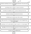
- Fig. 3 illustrates a method for self-calibration of an actuator.
- computer executable instructions may include routines, programs, objects, components and modules.
- the method 300 may be implemented in any suitable hardware, software, firmware, or combination thereof.
- the method 300 includes initializing actuation cycles of the actuator.
- the processor 120 is configured to initialize actuation cycles of the actuator.
- the method 300 includes detecting an instantaneous pressure of the actuator and generating a first pressure signal.
- the first set of sensors 102 is configured to sense an operating pressure of the actuator and generate a pressure signal.
- the method 300 includes converting the pressure signal and generating a first conditioned signal.
- the first signal conditioning circuit 104 is configured to receive the pressure signal to generate a first conditioned signal.
- the method 300 includes detecting at least one spike in the first conditioned signal at a first instant of time.
- the detector 106 is configured to detect a spike in the first conditioned signal and generate a spike status signal at every instant of time.
- the method 300 includes incrementing the operating pressure by a first predetermined value until a first spike is detected.
- the pressure control circuit 108 is configured to increment the operating pressure of the actuator by a first pre-determined value until a spike is detected.
- the method 300 includes setting the operating pressure to a second predetermined value if the first spike is detected.
- the pressure control circuit 108 is configured to set the operating pressure to a second predetermined value if the spike is detected.
- the method 300 includes detecting at least one spike in the first conditioned signal at a second instant of time.
- the detector 106 is configured to detect at least one spike in the first conditioned signal at a second instant of time.
- the method 300 includes incrementing the operating pressure by the first predetermined value until a second spike is detected.
- the pressure control circuit 106 is configured to increment the operating pressure by the first predetermined value until a second spike is detected.
- the method 300 includes setting the operating pressure to a third predetermined value if the second spike is detected.
- the pressure control circuit 106 is configured to set the operating pressure to a third predetermined value if the second spike is detected.
- the method 300 includes generating a first error signal if no spikes are detected.
- the pressure control circuit 108 is configured to generate a first error signal if no spikes are detected.
- the method 300 includes converting the operating pressure to generate operating pressure data.
- the processor 120 is configured to convert the operating pressure to generate operating pressure data.
- the method 300 includes storing the operating pressure data in the memory.
- the processor 120 is configured to store the operating pressure data in the memory.
- the method 300 includes re-initializing the actuation cycles of the actuator.
- the processor 120 is configured to re-initialize the actuation cycles of the actuator.
- the method 300 includes detecting rotation of the actuator during the actuation cycles and generating a set of rotation signals.
- the second set of sensors 114 is configured to detect rotation of the actuator during the actuation cycles and generate a set of rotation signals.
- the method 300 includes generating a set of second conditioned signals using the set of rotation signals.
- the second signal conditioning circuit 116 is configured to generate a set of second conditioned signals using the set of rotation signals.
- the method 300 includes generating a set of travel limit signals using the set of second conditioned signals.
- the digital signal processing circuit 118 is configured to generate a set of travel limit signals using the set of second conditioned signals.
- the method 300 includes storing the set of travel limit signals.
- the processor 120 is configured to store the set of travel limit signals.
- the method 300 includes generating operating torque profile data using the operating pressure data and the set of travel limit signals, and storing the set of torque profile data in the memory.
- the processor 120 is configured to generate operating torque profile data using the operating pressure data and the set of travel limit signals and store the set of torque profile data.
- the method 300 includes detecting a set of parameters of the actuator and generating a set of profile signals.
- the third set of sensors 110 is configured to detect a set of parameters of the actuator and generate a set of profile signals.
- the method 300 includes generating a set of third conditioned signals using the set of profile signals.
- the third signal conditioning circuit 112 is configured to generate a set of third conditioned signals using the set of profile signals.
- the method 300 includes converting the set of third conditioned signals and generating a set of profile data.
- the processor 120 is configured to convert the set of third conditioned signals and generating a set of profile data.
- the method 300 includes storing the set of profile data.
- the processor 120 is configured to store the set of profile data in the memory.
- a step at block 328 is repeated for at least two actuation cycles thereby generating a set of rotation signals for each of the rotation cycles and is further succeeded by the step of generating the set of second conditioned signals for each of the set of rotation signals associated with each of the at least two rotation cycles.
- the step of generating the set of second conditioned signals for each of the set of rotation signals associated with each of the at least two rotation cycles is succeeded by the steps of:
- the step of generating a second error signal is succeeded by the following steps:
Landscapes
- Engineering & Computer Science (AREA)
- General Engineering & Computer Science (AREA)
- Mechanical Engineering (AREA)
- Physics & Mathematics (AREA)
- General Physics & Mathematics (AREA)
- Automation & Control Theory (AREA)
- Fluid Mechanics (AREA)
- Human Computer Interaction (AREA)
- Manufacturing & Machinery (AREA)
- Control Of Electric Motors In General (AREA)
- Fluid-Pressure Circuits (AREA)
Applications Claiming Priority (1)
| Application Number | Priority Date | Filing Date | Title |
|---|---|---|---|
| IN201621010857 | 2016-03-29 |
Publications (2)
| Publication Number | Publication Date |
|---|---|
| EP3232069A1 true EP3232069A1 (fr) | 2017-10-18 |
| EP3232069B1 EP3232069B1 (fr) | 2018-12-19 |
Family
ID=58401430
Family Applications (1)
| Application Number | Title | Priority Date | Filing Date |
|---|---|---|---|
| EP17162107.1A Active EP3232069B1 (fr) | 2016-03-29 | 2017-03-21 | Système et procédé d'auto-étalonnage d'un actionneur |
Country Status (4)
| Country | Link |
|---|---|
| US (1) | US10139804B2 (fr) |
| EP (1) | EP3232069B1 (fr) |
| CN (1) | CN107239051B (fr) |
| CA (1) | CA2962014C (fr) |
Families Citing this family (1)
| Publication number | Priority date | Publication date | Assignee | Title |
|---|---|---|---|---|
| CN113456236B (zh) * | 2021-06-29 | 2022-05-27 | 北京理工大学 | 绳驱动并联主操作手 |
Citations (4)
| Publication number | Priority date | Publication date | Assignee | Title |
|---|---|---|---|---|
| EP0591925A2 (fr) * | 1992-10-05 | 1994-04-13 | Fisher Controls International, Inc. | Calibration de convertisseur électro-pneumatique |
| EP1150031A1 (fr) * | 2000-04-27 | 2001-10-31 | Eaton Corporation | Système et procédé à auto-étalonnage pour contrôler un dispositif hydraulique |
| US6615114B1 (en) * | 1999-12-15 | 2003-09-02 | Caterpillar Inc | Calibration system and method for work machines using electro hydraulic controls |
| US20140163805A1 (en) * | 2012-12-12 | 2014-06-12 | Caterpillar Inc. | Method of modifying a worksite |
Family Cites Families (9)
| Publication number | Priority date | Publication date | Assignee | Title |
|---|---|---|---|---|
| US6671641B1 (en) * | 2000-11-15 | 2003-12-30 | Delphi Technologies, Inc. | Method for calibrating hydraulic actuators |
| US7562554B2 (en) * | 2006-08-31 | 2009-07-21 | Caterpillar Inc. | Method for calibrating independent metering valves |
| US8170761B2 (en) * | 2008-03-03 | 2012-05-01 | Delphi Technologies, Inc. | Method for real-time learning of actuator transfer characteristics |
| US8321059B2 (en) * | 2009-08-28 | 2012-11-27 | Fisher Controls International, Llc | Apparatus, methods and articles of manufacture to calibrate valve-mounted instruments |
| IT1396413B1 (it) * | 2009-10-30 | 2012-11-19 | Natali | Metodo per la taratura di attuatori pneumatici ed attuatore tarato cosi' ottenibile. |
| US8412407B2 (en) * | 2010-09-16 | 2013-04-02 | GM Global Technology Operations LLC | Calibration control systems and methods |
| US20120167996A1 (en) * | 2011-01-05 | 2012-07-05 | Fisher Controls International Llc | Valve Controller Automatic Calibration Without User Interface |
| CN202182232U (zh) * | 2011-06-13 | 2012-04-04 | 费希尔控制国际公司 | 用于阀组件的致动器以及用于电动机和阀组件的控制系统 |
| US9423050B2 (en) * | 2013-04-09 | 2016-08-23 | Fisher Controls International Llc | Intelligent actuator and method of monitoring actuator health and integrity |
-
2017
- 2017-03-16 US US15/460,770 patent/US10139804B2/en active Active
- 2017-03-21 EP EP17162107.1A patent/EP3232069B1/fr active Active
- 2017-03-23 CA CA2962014A patent/CA2962014C/fr active Active
- 2017-03-29 CN CN201710197471.XA patent/CN107239051B/zh active Active
Patent Citations (4)
| Publication number | Priority date | Publication date | Assignee | Title |
|---|---|---|---|---|
| EP0591925A2 (fr) * | 1992-10-05 | 1994-04-13 | Fisher Controls International, Inc. | Calibration de convertisseur électro-pneumatique |
| US6615114B1 (en) * | 1999-12-15 | 2003-09-02 | Caterpillar Inc | Calibration system and method for work machines using electro hydraulic controls |
| EP1150031A1 (fr) * | 2000-04-27 | 2001-10-31 | Eaton Corporation | Système et procédé à auto-étalonnage pour contrôler un dispositif hydraulique |
| US20140163805A1 (en) * | 2012-12-12 | 2014-06-12 | Caterpillar Inc. | Method of modifying a worksite |
Also Published As
| Publication number | Publication date |
|---|---|
| CN107239051A (zh) | 2017-10-10 |
| US20170285607A1 (en) | 2017-10-05 |
| EP3232069B1 (fr) | 2018-12-19 |
| CA2962014A1 (fr) | 2017-09-29 |
| CN107239051B (zh) | 2022-04-12 |
| CA2962014C (fr) | 2023-03-21 |
| US10139804B2 (en) | 2018-11-27 |
Similar Documents
| Publication | Publication Date | Title |
|---|---|---|
| RU2717634C2 (ru) | Способ калибровки позиционера, система управления процессом и компьютерное устройство для регулирования давления для калибровки устройств управления процессом | |
| RU2691675C2 (ru) | Способы и устройства для испытания клапанов при неполном ходе с применением управления давлением | |
| RU2528222C2 (ru) | Калибровка клапанов | |
| US8991268B2 (en) | Method for determining the break-away force of an actuator | |
| EP1984630B1 (fr) | Circuit de dépassement de sécurité pour positionneur pneumatique et procédé d'utilisation de celui-ci | |
| CN203838494U (zh) | 用于限制电气动控制器中驱动值的变化的装置 | |
| EP3232069B1 (fr) | Système et procédé d'auto-étalonnage d'un actionneur | |
| KR20060047815A (ko) | 변위량 측정장치 | |
| US9778069B2 (en) | Determining a position of a hydraulic subsea actuator | |
| CN108292127B (zh) | 包括滑动联接单元的电驱动系统 | |
| SA521430138B1 (ar) | نظام وطريقة لمراقبة وتشخيصات جهاز مشغل لتشغيل صمام لخطوط أنابيب المائع، وجهاز المشغل الذي يُكون جزءًا من هذا النظام | |
| DE10318171B4 (de) | Verfahren zur funktionsüberwachten Bestimmung einer Ventilstellung sowie ein in diesem Verfahren verwendbarer Ventilstellungsaufnehmer und Verwendung desselben | |
| US20150202814A1 (en) | Controller for injection molding machine having function of reducing synchronous errors | |
| US20100181513A1 (en) | Method and electronic device for finding the opening point for a regulated electropneumatic valve of a pneumatic actuating drive | |
| CN104088842B (zh) | 一种比例方向阀控制死区的自动识别及补偿方法和系统 | |
| JPS5825209B2 (ja) | 自動補正システム | |
| EP2426462B1 (fr) | Procédé et dispositif pour corriger les valeurs extrèmes d'un capteur | |
| US5204674A (en) | Servo mechanism with differential phase shift feedback | |
| US8281705B2 (en) | Method for detecting the drive type of an actuator (II) | |
| SE1550334A1 (sv) | A drive unit for controlling a control valve element, a method for operating a drive unit of a control valve element and a control valve unit | |
| WO2023217935A1 (fr) | Système d'actionneur pneumatique | |
| Savaresi et al. | On speed estimation from incremental encoders with tunable error bounds | |
| CN102095353A (zh) | 用于提高位移/位置测量系统的可用性的方法 | |
| JP6625640B2 (ja) | 圧力測定装置、および液圧区間を備えるクラッチアクチュエータ装置 | |
| US11307103B2 (en) | Method and device for determining a mechanical load |
Legal Events
| Date | Code | Title | Description |
|---|---|---|---|
| PUAI | Public reference made under article 153(3) epc to a published international application that has entered the european phase |
Free format text: ORIGINAL CODE: 0009012 |
|
| STAA | Information on the status of an ep patent application or granted ep patent |
Free format text: STATUS: THE APPLICATION HAS BEEN PUBLISHED |
|
| AK | Designated contracting states |
Kind code of ref document: A1 Designated state(s): AL AT BE BG CH CY CZ DE DK EE ES FI FR GB GR HR HU IE IS IT LI LT LU LV MC MK MT NL NO PL PT RO RS SE SI SK SM TR |
|
| AX | Request for extension of the european patent |
Extension state: BA ME |
|
| STAA | Information on the status of an ep patent application or granted ep patent |
Free format text: STATUS: REQUEST FOR EXAMINATION WAS MADE |
|
| 17P | Request for examination filed |
Effective date: 20180412 |
|
| RBV | Designated contracting states (corrected) |
Designated state(s): AL AT BE BG CH CY CZ DE DK EE ES FI FR GB GR HR HU IE IS IT LI LT LU LV MC MK MT NL NO PL PT RO RS SE SI SK SM TR |
|
| REG | Reference to a national code |
Ref country code: DE Ref legal event code: R079 Ref document number: 602017001421 Country of ref document: DE Free format text: PREVIOUS MAIN CLASS: F15B0019000000 Ipc: F16K0037000000 |
|
| GRAP | Despatch of communication of intention to grant a patent |
Free format text: ORIGINAL CODE: EPIDOSNIGR1 |
|
| STAA | Information on the status of an ep patent application or granted ep patent |
Free format text: STATUS: GRANT OF PATENT IS INTENDED |
|
| RIC1 | Information provided on ipc code assigned before grant |
Ipc: F16K 31/02 20060101ALI20180618BHEP Ipc: F16K 37/00 20060101AFI20180618BHEP Ipc: F15B 19/00 20060101ALI20180618BHEP Ipc: G05B 19/37 20060101ALI20180618BHEP |
|
| INTG | Intention to grant announced |
Effective date: 20180719 |
|
| GRAS | Grant fee paid |
Free format text: ORIGINAL CODE: EPIDOSNIGR3 |
|
| GRAA | (expected) grant |
Free format text: ORIGINAL CODE: 0009210 |
|
| STAA | Information on the status of an ep patent application or granted ep patent |
Free format text: STATUS: THE PATENT HAS BEEN GRANTED |
|
| AK | Designated contracting states |
Kind code of ref document: B1 Designated state(s): AL AT BE BG CH CY CZ DE DK EE ES FI FR GB GR HR HU IE IS IT LI LT LU LV MC MK MT NL NO PL PT RO RS SE SI SK SM TR |
|
| REG | Reference to a national code |
Ref country code: GB Ref legal event code: FG4D |
|
| REG | Reference to a national code |
Ref country code: CH Ref legal event code: EP |
|
| REG | Reference to a national code |
Ref country code: IE Ref legal event code: FG4D |
|
| REG | Reference to a national code |
Ref country code: DE Ref legal event code: R096 Ref document number: 602017001421 Country of ref document: DE |
|
| REG | Reference to a national code |
Ref country code: AT Ref legal event code: REF Ref document number: 1079098 Country of ref document: AT Kind code of ref document: T Effective date: 20190115 |
|
| REG | Reference to a national code |
Ref country code: NL Ref legal event code: FP |
|
| PG25 | Lapsed in a contracting state [announced via postgrant information from national office to epo] |
Ref country code: LT Free format text: LAPSE BECAUSE OF FAILURE TO SUBMIT A TRANSLATION OF THE DESCRIPTION OR TO PAY THE FEE WITHIN THE PRESCRIBED TIME-LIMIT Effective date: 20181219 Ref country code: NO Free format text: LAPSE BECAUSE OF FAILURE TO SUBMIT A TRANSLATION OF THE DESCRIPTION OR TO PAY THE FEE WITHIN THE PRESCRIBED TIME-LIMIT Effective date: 20190319 Ref country code: FI Free format text: LAPSE BECAUSE OF FAILURE TO SUBMIT A TRANSLATION OF THE DESCRIPTION OR TO PAY THE FEE WITHIN THE PRESCRIBED TIME-LIMIT Effective date: 20181219 Ref country code: BG Free format text: LAPSE BECAUSE OF FAILURE TO SUBMIT A TRANSLATION OF THE DESCRIPTION OR TO PAY THE FEE WITHIN THE PRESCRIBED TIME-LIMIT Effective date: 20190319 Ref country code: HR Free format text: LAPSE BECAUSE OF FAILURE TO SUBMIT A TRANSLATION OF THE DESCRIPTION OR TO PAY THE FEE WITHIN THE PRESCRIBED TIME-LIMIT Effective date: 20181219 Ref country code: LV Free format text: LAPSE BECAUSE OF FAILURE TO SUBMIT A TRANSLATION OF THE DESCRIPTION OR TO PAY THE FEE WITHIN THE PRESCRIBED TIME-LIMIT Effective date: 20181219 |
|
| REG | Reference to a national code |
Ref country code: LT Ref legal event code: MG4D |
|
| REG | Reference to a national code |
Ref country code: AT Ref legal event code: MK05 Ref document number: 1079098 Country of ref document: AT Kind code of ref document: T Effective date: 20181219 |
|
| PG25 | Lapsed in a contracting state [announced via postgrant information from national office to epo] |
Ref country code: RS Free format text: LAPSE BECAUSE OF FAILURE TO SUBMIT A TRANSLATION OF THE DESCRIPTION OR TO PAY THE FEE WITHIN THE PRESCRIBED TIME-LIMIT Effective date: 20181219 Ref country code: SE Free format text: LAPSE BECAUSE OF FAILURE TO SUBMIT A TRANSLATION OF THE DESCRIPTION OR TO PAY THE FEE WITHIN THE PRESCRIBED TIME-LIMIT Effective date: 20181219 Ref country code: GR Free format text: LAPSE BECAUSE OF FAILURE TO SUBMIT A TRANSLATION OF THE DESCRIPTION OR TO PAY THE FEE WITHIN THE PRESCRIBED TIME-LIMIT Effective date: 20190320 Ref country code: AL Free format text: LAPSE BECAUSE OF FAILURE TO SUBMIT A TRANSLATION OF THE DESCRIPTION OR TO PAY THE FEE WITHIN THE PRESCRIBED TIME-LIMIT Effective date: 20181219 |
|
| PG25 | Lapsed in a contracting state [announced via postgrant information from national office to epo] |
Ref country code: PL Free format text: LAPSE BECAUSE OF FAILURE TO SUBMIT A TRANSLATION OF THE DESCRIPTION OR TO PAY THE FEE WITHIN THE PRESCRIBED TIME-LIMIT Effective date: 20181219 Ref country code: ES Free format text: LAPSE BECAUSE OF FAILURE TO SUBMIT A TRANSLATION OF THE DESCRIPTION OR TO PAY THE FEE WITHIN THE PRESCRIBED TIME-LIMIT Effective date: 20181219 Ref country code: CZ Free format text: LAPSE BECAUSE OF FAILURE TO SUBMIT A TRANSLATION OF THE DESCRIPTION OR TO PAY THE FEE WITHIN THE PRESCRIBED TIME-LIMIT Effective date: 20181219 Ref country code: PT Free format text: LAPSE BECAUSE OF FAILURE TO SUBMIT A TRANSLATION OF THE DESCRIPTION OR TO PAY THE FEE WITHIN THE PRESCRIBED TIME-LIMIT Effective date: 20190419 |
|
| PG25 | Lapsed in a contracting state [announced via postgrant information from national office to epo] |
Ref country code: IS Free format text: LAPSE BECAUSE OF FAILURE TO SUBMIT A TRANSLATION OF THE DESCRIPTION OR TO PAY THE FEE WITHIN THE PRESCRIBED TIME-LIMIT Effective date: 20190419 Ref country code: RO Free format text: LAPSE BECAUSE OF FAILURE TO SUBMIT A TRANSLATION OF THE DESCRIPTION OR TO PAY THE FEE WITHIN THE PRESCRIBED TIME-LIMIT Effective date: 20181219 Ref country code: EE Free format text: LAPSE BECAUSE OF FAILURE TO SUBMIT A TRANSLATION OF THE DESCRIPTION OR TO PAY THE FEE WITHIN THE PRESCRIBED TIME-LIMIT Effective date: 20181219 Ref country code: SM Free format text: LAPSE BECAUSE OF FAILURE TO SUBMIT A TRANSLATION OF THE DESCRIPTION OR TO PAY THE FEE WITHIN THE PRESCRIBED TIME-LIMIT Effective date: 20181219 Ref country code: SK Free format text: LAPSE BECAUSE OF FAILURE TO SUBMIT A TRANSLATION OF THE DESCRIPTION OR TO PAY THE FEE WITHIN THE PRESCRIBED TIME-LIMIT Effective date: 20181219 |
|
| REG | Reference to a national code |
Ref country code: DE Ref legal event code: R097 Ref document number: 602017001421 Country of ref document: DE |
|
| PLBE | No opposition filed within time limit |
Free format text: ORIGINAL CODE: 0009261 |
|
| STAA | Information on the status of an ep patent application or granted ep patent |
Free format text: STATUS: NO OPPOSITION FILED WITHIN TIME LIMIT |
|
| PG25 | Lapsed in a contracting state [announced via postgrant information from national office to epo] |
Ref country code: MC Free format text: LAPSE BECAUSE OF FAILURE TO SUBMIT A TRANSLATION OF THE DESCRIPTION OR TO PAY THE FEE WITHIN THE PRESCRIBED TIME-LIMIT Effective date: 20181219 Ref country code: AT Free format text: LAPSE BECAUSE OF FAILURE TO SUBMIT A TRANSLATION OF THE DESCRIPTION OR TO PAY THE FEE WITHIN THE PRESCRIBED TIME-LIMIT Effective date: 20181219 Ref country code: DK Free format text: LAPSE BECAUSE OF FAILURE TO SUBMIT A TRANSLATION OF THE DESCRIPTION OR TO PAY THE FEE WITHIN THE PRESCRIBED TIME-LIMIT Effective date: 20181219 |
|
| 26N | No opposition filed |
Effective date: 20190920 |
|
| PG25 | Lapsed in a contracting state [announced via postgrant information from national office to epo] |
Ref country code: LU Free format text: LAPSE BECAUSE OF NON-PAYMENT OF DUE FEES Effective date: 20190321 |
|
| REG | Reference to a national code |
Ref country code: BE Ref legal event code: MM Effective date: 20190331 |
|
| PG25 | Lapsed in a contracting state [announced via postgrant information from national office to epo] |
Ref country code: IE Free format text: LAPSE BECAUSE OF NON-PAYMENT OF DUE FEES Effective date: 20190321 |
|
| PG25 | Lapsed in a contracting state [announced via postgrant information from national office to epo] |
Ref country code: BE Free format text: LAPSE BECAUSE OF NON-PAYMENT OF DUE FEES Effective date: 20190331 Ref country code: SI Free format text: LAPSE BECAUSE OF FAILURE TO SUBMIT A TRANSLATION OF THE DESCRIPTION OR TO PAY THE FEE WITHIN THE PRESCRIBED TIME-LIMIT Effective date: 20181219 |
|
| PG25 | Lapsed in a contracting state [announced via postgrant information from national office to epo] |
Ref country code: TR Free format text: LAPSE BECAUSE OF FAILURE TO SUBMIT A TRANSLATION OF THE DESCRIPTION OR TO PAY THE FEE WITHIN THE PRESCRIBED TIME-LIMIT Effective date: 20181219 |
|
| PG25 | Lapsed in a contracting state [announced via postgrant information from national office to epo] |
Ref country code: MT Free format text: LAPSE BECAUSE OF NON-PAYMENT OF DUE FEES Effective date: 20190321 |
|
| REG | Reference to a national code |
Ref country code: CH Ref legal event code: PL |
|
| PG25 | Lapsed in a contracting state [announced via postgrant information from national office to epo] |
Ref country code: CH Free format text: LAPSE BECAUSE OF NON-PAYMENT OF DUE FEES Effective date: 20200331 Ref country code: LI Free format text: LAPSE BECAUSE OF NON-PAYMENT OF DUE FEES Effective date: 20200331 |
|
| PG25 | Lapsed in a contracting state [announced via postgrant information from national office to epo] |
Ref country code: CY Free format text: LAPSE BECAUSE OF FAILURE TO SUBMIT A TRANSLATION OF THE DESCRIPTION OR TO PAY THE FEE WITHIN THE PRESCRIBED TIME-LIMIT Effective date: 20181219 |
|
| PG25 | Lapsed in a contracting state [announced via postgrant information from national office to epo] |
Ref country code: HU Free format text: LAPSE BECAUSE OF FAILURE TO SUBMIT A TRANSLATION OF THE DESCRIPTION OR TO PAY THE FEE WITHIN THE PRESCRIBED TIME-LIMIT; INVALID AB INITIO Effective date: 20170321 |
|
| REG | Reference to a national code |
Ref country code: DE Ref legal event code: R082 Ref document number: 602017001421 Country of ref document: DE Representative=s name: ZACCO LEGAL RECHTSANWALTSGESELLSCHAFT MBH, DE |
|
| PG25 | Lapsed in a contracting state [announced via postgrant information from national office to epo] |
Ref country code: MK Free format text: LAPSE BECAUSE OF FAILURE TO SUBMIT A TRANSLATION OF THE DESCRIPTION OR TO PAY THE FEE WITHIN THE PRESCRIBED TIME-LIMIT Effective date: 20181219 |
|
| P01 | Opt-out of the competence of the unified patent court (upc) registered |
Effective date: 20230526 |
|
| REG | Reference to a national code |
Ref country code: DE Ref legal event code: R082 Ref document number: 602017001421 Country of ref document: DE |
|
| PGFP | Annual fee paid to national office [announced via postgrant information from national office to epo] |
Ref country code: NL Payment date: 20260219 Year of fee payment: 10 |
|
| PGFP | Annual fee paid to national office [announced via postgrant information from national office to epo] |
Ref country code: GB Payment date: 20260219 Year of fee payment: 10 |
|
| PGFP | Annual fee paid to national office [announced via postgrant information from national office to epo] |
Ref country code: DE Payment date: 20260219 Year of fee payment: 10 |
|
| PGFP | Annual fee paid to national office [announced via postgrant information from national office to epo] |
Ref country code: IT Payment date: 20260219 Year of fee payment: 10 |
|
| PGFP | Annual fee paid to national office [announced via postgrant information from national office to epo] |
Ref country code: FR Payment date: 20260219 Year of fee payment: 10 |