EP3232076B1 - Module comprenant un dispositif de friction - Google Patents
Module comprenant un dispositif de friction Download PDFInfo
- Publication number
- EP3232076B1 EP3232076B1 EP17166199.4A EP17166199A EP3232076B1 EP 3232076 B1 EP3232076 B1 EP 3232076B1 EP 17166199 A EP17166199 A EP 17166199A EP 3232076 B1 EP3232076 B1 EP 3232076B1
- Authority
- EP
- European Patent Office
- Prior art keywords
- region
- spring
- component
- wrap spring
- friction
- Prior art date
- Legal status (The legal status is an assumption and is not a legal conclusion. Google has not performed a legal analysis and makes no representation as to the accuracy of the status listed.)
- Active
Links
Images






Classifications
-
- F—MECHANICAL ENGINEERING; LIGHTING; HEATING; WEAPONS; BLASTING
- F16—ENGINEERING ELEMENTS AND UNITS; GENERAL MEASURES FOR PRODUCING AND MAINTAINING EFFECTIVE FUNCTIONING OF MACHINES OR INSTALLATIONS; THERMAL INSULATION IN GENERAL
- F16D—COUPLINGS FOR TRANSMITTING ROTATION; CLUTCHES; BRAKES
- F16D13/00—Friction clutches
- F16D13/22—Friction clutches with axially-movable clutching members
- F16D13/38—Friction clutches with axially-movable clutching members with flat clutching surfaces, e.g. discs
- F16D13/46—Friction clutches with axially-movable clutching members with flat clutching surfaces, e.g. discs in which two axially-movable members, of which one is attached to the driving side and the other to the driven side, are pressed from one side towards an axially-located member
- F16D13/48—Friction clutches with axially-movable clutching members with flat clutching surfaces, e.g. discs in which two axially-movable members, of which one is attached to the driving side and the other to the driven side, are pressed from one side towards an axially-located member with means for increasing the effective force between the actuating sleeve or equivalent member and the pressure member
- F16D13/50—Friction clutches with axially-movable clutching members with flat clutching surfaces, e.g. discs in which two axially-movable members, of which one is attached to the driving side and the other to the driven side, are pressed from one side towards an axially-located member with means for increasing the effective force between the actuating sleeve or equivalent member and the pressure member in which the clutching pressure is produced by springs only
-
- F—MECHANICAL ENGINEERING; LIGHTING; HEATING; WEAPONS; BLASTING
- F16—ENGINEERING ELEMENTS AND UNITS; GENERAL MEASURES FOR PRODUCING AND MAINTAINING EFFECTIVE FUNCTIONING OF MACHINES OR INSTALLATIONS; THERMAL INSULATION IN GENERAL
- F16D—COUPLINGS FOR TRANSMITTING ROTATION; CLUTCHES; BRAKES
- F16D13/00—Friction clutches
- F16D13/08—Friction clutches with a helical band or equivalent member, which may be built up from linked parts, with more than one turn embracing a drum or the like, with or without an additional clutch actuating the end of the band
-
- F—MECHANICAL ENGINEERING; LIGHTING; HEATING; WEAPONS; BLASTING
- F16—ENGINEERING ELEMENTS AND UNITS; GENERAL MEASURES FOR PRODUCING AND MAINTAINING EFFECTIVE FUNCTIONING OF MACHINES OR INSTALLATIONS; THERMAL INSULATION IN GENERAL
- F16D—COUPLINGS FOR TRANSMITTING ROTATION; CLUTCHES; BRAKES
- F16D28/00—Electrically-actuated clutches
-
- F—MECHANICAL ENGINEERING; LIGHTING; HEATING; WEAPONS; BLASTING
- F16—ENGINEERING ELEMENTS AND UNITS; GENERAL MEASURES FOR PRODUCING AND MAINTAINING EFFECTIVE FUNCTIONING OF MACHINES OR INSTALLATIONS; THERMAL INSULATION IN GENERAL
- F16D—COUPLINGS FOR TRANSMITTING ROTATION; CLUTCHES; BRAKES
- F16D23/00—Details of mechanically-actuated clutches not specific for one distinct type
- F16D23/12—Mechanical clutch-actuating mechanisms arranged outside the clutch as such
- F16D2023/123—Clutch actuation by cams, ramps or ball-screw mechanisms
-
- F—MECHANICAL ENGINEERING; LIGHTING; HEATING; WEAPONS; BLASTING
- F16—ENGINEERING ELEMENTS AND UNITS; GENERAL MEASURES FOR PRODUCING AND MAINTAINING EFFECTIVE FUNCTIONING OF MACHINES OR INSTALLATIONS; THERMAL INSULATION IN GENERAL
- F16D—COUPLINGS FOR TRANSMITTING ROTATION; CLUTCHES; BRAKES
- F16D29/00—Clutches and systems of clutches involving both fluid and magnetic actuation
- F16D29/005—Clutches and systems of clutches involving both fluid and magnetic actuation with a fluid pressure piston driven by an electric motor
Definitions
- the invention relates to an assembly having a friction device with at least two relatively rotatable components, in particular for use in a transmission and / or an actuator.
- Actuators are used for example for actuating a clutch of a vehicle and can convert the rotational movement of a component into an axial movement of another component.
- Planetenskylzgewindespindeltriebe are formed from a spindle, a spindle nut and between them arranged over the circumference, received in a planet carrier PlanetenxxlzSystemn.
- the spindle, spindle nut and PlanetenskylzSystem on profiling to transmit a rotational movement between the spindle and spindle nut, wherein one of the components - spindle or spindle nut - rotatably driven and the other component in a rotationally fixed arrangement along the longitudinal axis of the spindle by one of the set translation corresponding Axialweg is relocated.
- the Planetenannalz analyses two different profile sections which mesh on the one hand with the spindle and on the other hand with the spindle nut
- the profile sections on the Planetenannalz analyses grooved and the other profile sections on the Planetenracelz analyses are generally grooved and depending on the embodiment, a complementary threaded portion on the spindle or the spindle nut and according to the groove portion is arranged on the other component.
- a PWG is known in which the spindle has a thread and the spindle nut grooves, on each of which PlanetenracelzSystem by means of roll over complementarily formed profile sections.
- the axially fixed and rotatably driven for example by an electric motor spindle relative to the rotatably mounted spindle nut is rotated, so that the spindle nut is forcibly displaced axially and by the frictional rolling of the planetary body in the grooves of the spindle nut.
- planetary gears of the planet carrier rotates with the planetary rollers at half speed or another ratio, depending on the design of the diameter of the rotating component, namely spindle or spindle nut.
- the DE 10 2010 047 800 A1 shows an application of a Planetenskylzgetriebes, in which designed as a piston of a master cylinder Aktorteil a Hydrostataktors axially fixed to the rotatably and axially displaceably arranged spindle is coupled, wherein the axially fixed spindle nut is rotationally driven by an electric motor, so that upon rotation of the spindle nut spindle and Spindle nut are shifted against each other along the Axialwegs.
- the piston Since the piston accommodating and forming a pressure chamber with this cylinder housing is fixed and the spindle nut is axially supported on this, the piston builds depending on the rotary drive of the spindle nut pressure, for example for actuation of automotive components such as brakes, friction clutch and the like. It is particularly desirable for friction clutches to quickly bridge a clearance with low load request by means of a high pitch and be able to apply high loads with an electric motor with low power in the effective range of the friction clutch by means of a small slope.
- HCA Hydrostatic clutch actuators
- a decisive disadvantage of such actuators is that they require a permanent holding current or, in the event of a power failure / fault (eg cable break, connector drop) Position can not be held. If the clutch is pressed by the actuator, then there is a great danger that the clutch will close unintentionally.
- a power failure / fault eg cable break, connector drop
- wrap springs for example for clutches.
- the wrap spring clutch consists of a wound on a shaft or a cylindrical body coil spring, which is attached to one side of the drive.
- the entrainment effect is based on the fact that the driving torque increases and adds to each turn due to the friction. This increases because of the wrap at the same time the friction causing this force. In the opposite direction occurs only a slight friction - the spring slightly increases its diameter, but does not wrap. Often one uses their remaining in freewheeling friction as a friction clutch (see Wikipedia).
- a torsional vibration damper which has at least two counter to the action of a damping device with circumferentially acting energy storage to each other rotatable parts, one of which is connectable to a prime mover and the other with a driven shaft, wherein between the two parts additionally with the Damping device is provided in series connected torque limiter, which is effective at least in one of the relative rotational directions between the two parts and at least one Schlingenfederkupplung includes, which acts upon reaching a predetermined angle of rotation between the two parts as a freewheel and at least one loop spring element comprises.
- This solution is characterized in that at least one end of the loop spring element is non-rotatably connected to a ring element which has support regions for the energy storage devices acting in the circumferential direction and / or activation regions for the freewheeling effect.
- the object of the present invention is to develop an assembly with a friction device with at least two relatively rotatable components, which is provided in particular for use in a transmission and / or an actuator and with which the friction and thus the efficiency between the relative to each other rotatable components is changeable, for example, when used in an actuator for actuating a clutch to prevent inadvertent closing of the clutch in case of failure of the drive of the actuator or to reduce the holding current or exclude, without the efficiency of a spindle drive (against the load) Example when using an actuator with PWG significantly reduce.
- the assembly with friction device has at least two relatively rotatable components and is used in particular for use in transmission and / or an actuator, for example, for actuating a clutch of a vehicle, according to the invention between the relatively rotatable components at a relative rotation of the components the efficiency / the Friction influencing coil spring is arranged.
- this friction device in the manner of a coil spring, which at least partially forms a wrap, depending on the direction of rotation, the friction between the components in driving actuator against a load only slightly or when the load is significantly increased, thus efficiency-optimized / non-self-locking spindle drives in case of error ( Power failure).
- Another advantage is that a holding current through the friction element can be reduced or no longer required.
- the helical spring which is at least partially configured as a wrap spring, is preferably configured as a simple wrap spring or a double wrap spring or a loop torsion spring and operatively connected to a first component and to a second component that is rotatable or rotatable and axially displaceable relative to the first component.
- a drive gear which
- the helical spring in the form of a wrap spring or double wrap spring or the wrap torsion spring is arranged between a rotary element of a PWG or another gear and a housing-fixed part of the actuator or between two rotatable relative to each other at different speeds elements of the PWG or other transmission ,
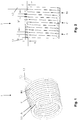
- the areas of the wrap / double wrap / Schling torsion spring are preferably wound from a tape and thus connected in the transition region C with each other, wherein the band may be twisted in the transition region C, so that the cross section of the tape in area A a first orientation and in Area B1 / B2 has a rotated orientation.
- a first region A acting as a wrap-around spring has a first end 1.1 bent radially outward, with a constant friction at the end 1.1 or a constant or variable bias across the first region A to a hub (a Outer diameter) to produce friction.
- acting as a torsion spring second region B1 with a second end 1.2 is present, which is also bent radially outward.
- a transition region C connects the regions A and B with each other. The outer diameter and the inner diameter of the turns are greater in the areas B1 and C than in the area A.
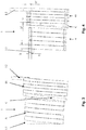
- the Schling torsion spring 1 also has areas A, B1, C, but the area C is twisted by 90 °.
- the rectangular cross-section of the turns thus has in the first region A a Height h and a width b, which is formed by twisting in the region C by 90 ° then in the second region B1, which acts as a torsion spring, such that the height h * in B of the width b in A and the width b * in B1 corresponds to the height h in A.
- the end 1.1 of the first region A is made blunt.
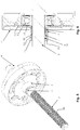
- FIGS. 5 to 9 is shown how, for example, a spindle 2 of a PWG with the designed as a wrap-torsion spring coil spring 1 gem.
- FIGS. 1 and 2 combined.
- FIG. 5 shows the three-dimensional representation of a threaded spindle / spindle 2 of a PWG, which is mounted in a, a spring housing 3 housing-receiving housing 4 and FIG. 6 the longitudinal section according to FIG. 5 in the region of the housing 4.
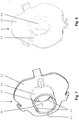
- the spring cup 3 according to the FIGS. 5 and 6 in a three-dimensional representation is from the direction of the front side 3.1 in FIG. 7 and from the direction of the flange 3.3 in FIG. 8 shown. It can be seen that the inner diameter 3d is formed on a bush-like region 3.4. At this is also in comparison to the end-side end face 3.1 'recessed end face 3.1, with which the not shown here end 1.1 of the coil spring, which forms the Schlingfeder- first area cooperates.
- the recessed face 3.1 are two circumferentially spaced stops 3.5 for the radially outwardly angled first end 1.1 of the wrap / first area A (s. Fig. 1 and 2 ) educated.
- the recess 3.2 is formed like a bead in the flange 3.3.
- the second end 1.2 of the torsion spring / second region B1 is mounted rotationally fixed in the mounted state.
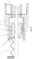
- FIG. 9 An actuator using a coil spring 1 according to the Figures 1 and 2 or already in the FIGS. 5 and 6 shown arrangement of the coil spring 1 is in FIG. 9 shown.
- the helical spring 1 embodied as a looping torsion spring is here fastened between the outer diameter of the threaded spindle / spindle 2 and the inner diameter of the spring cup 3, which is connected in a rotationally fixed manner to the housing 5 of the spindle bearing L.
- the first formed as a wrap region A has in the direction of the PWG 6 and the second formed as a torsion spring region B1 in the direction of the electric motor 7.
- the coil spring 1 is axially fixed.
- FIG. 10 A similar design of an actuator with PWG shows FIG. 10 - in contrast to FIG. 9
- a coil spring 1 in the form of a Schling torsion spring between spindle 2 and spring cup 3, which forms part of the PWG, wherein the spring cup 3 is rotatably mounted on the PWG housing 6.1.
- the second formed as a torsion spring region B1 points in the direction of the PWG 6 and the first designed as a wrap spring region A toward the housing 5.
- the coil spring 1 and the spring cup 3 are moved in the axial direction with the PWG housing 6.1.
- the second end 1.2 is also suspended in a recess 3.2 on the spring cup 3 rotatably.
- the wrap spring in the form of the first region A is rubbed against (at the first end 1.1 to the front side 3.1 of the spring cup 3. FIG. 6 ; or in the first region A between the outer diameter of the spindle 2 and inner diameter of the wrap spring) taken and twisted formed as a torsion spring second region B1.
- the change in diameter to the unloaded state must be maintained, to the torque balance between the restoring moment (due to the load) and torsional moment of the coil spring 1 in the second region B1, and is held in this position.
- the electric motor 7 must be energized. In this case, the first end 1.1 against the stop 3.5 (see FIG.
- the structure can also be reversed, so that the spring is connected to the end 2 with a rotating part (spindle) and rubs against a rotationally fixed component (spring cup).
- the friction and thus the efficiency are thus influenced for the first time by the interposition of a helical spring, which is at least partially formed as a loop spring, in an assembly, for example, a PWG.
- a helical spring which is at least partially formed as a loop spring
- the spindle does not rotate with.
- the wrap spring is clamped between the anti-rotation spring cup and the PWG.
- the wrap spring is connected via form over the other side by means of frictional engagement. Due to the friction, the spring contracts and leads to self-locking of the assembly.
- the loop spring end is placed against a corresponding stop and thus limits the friction torque. This overcomes the self-inhibition.
- the application in combination with another gear such as a ball screw (KGT) is possible.
- FIGS. 11 to 30 describes the use of a coil spring 1 in the form of a double wrap spring or a loop torsion spring, which is integrated in a transmission, here a PWG.
- FIG. 11 shows the schematic diagram of a variant of a coil spring 1 in the form of a Doppelschlingfeder with respect to a schematically arranged shaft 8 (first component) and hub 9 (second component) in the installed state and FIG. 12 the longitudinal section of the free Doppelschlingfeder gem.
- the coil spring 1 has gem.
- FIGS. 11 and 12 a first region A with a blunt end 1.1, wherein the first region A acts as a wrap spring and the outer diameter DA to the inner diameter d9 of the hub 9 is an in FIG. 12 drawn bias (also referred to as interference) or an excess a1 has.
- the second region B2 of the helical spring 1 is likewise designed as a wrap spring, but with a smaller diameter, and has a likewise blunt second end 1.2. Between the outer diameter D8 of the shaft 8 and the inner diameter dB2 of the second region B2 there is a bias voltage / oversize a2. Between the first area A and the second area B2 extends the transition area C.
- FIG. 13 is the three-dimensional representation of a coil spring 1 in the form of a double wrap spring with two blunt ends 1.1, 1.2 with a first acting as a wrap spring region A, a second acting as a wrap spring region B2, which has a smaller outer and inner diameter than the first region A. and in Fig. 14 the longitudinal section of it.
- the transition region C is twisted / twisted by 90 °, as in the Schling torsion spring acc.
- the rectangular cross-section of the turns in the first region A has a height h and a width b which is formed by twisting in the region C by 90 ° then in the second region B2 acting as a wrap spring such that the height h * in B2 corresponds to the width b in A and the width b * in B2 corresponds to the height h in A.
- a coil spring 1 which is also designed as a double wrap spring, but with a non-twisted transition region C between the first Schlingfeder Avenue A and the second Schlingfeder Symposium B2 show the FIGS. 15 and 16 ,
- the first and second ends 1.1, 1.2 here are also made blunt and outer and inner diameter of the second region B2 are smaller than the outer and inner diameter of the first region A.
- FIG. 17 shows a first variant of the design of the excess of a coil spring 1 as Doppelschlingfeder with two blunt ends, installed on the left and right free.
- the first region A has a larger diameter in the non-installed free state than the second region B2 (regions A and B2 act as wrap springs), so that they have a substantially same diameter in the installed state (left illustration).
- the helical spring designed as a double wrap spring has a substantially uniform outer and inner diameter in the initial state, wherein, when installed, the outer diameter of the first region A becomes smaller than the outer diameter of the second region B2.
- the shaft 8 has an outer diameter D8 and the second region B1 an inner diameter dB, so that there is an interference a2 (interference) between them. Between the inner diameter d9 of the hub 9 and the outer diameter of the first region A is an oversize / an interference a1 present. Due to the different output forms of the coil springs 1 in the non-installed state arise in conjunction with the excess dimensions of the shaft and hub different installation conditions in the FIGS. 17 and 18 ,
- the variant according to FIG. 18 is for the manufacturability of the coil spring 1 of advantage (constant winding diameter).
- the variants after Fig. 18 conditioned that shaft 8 and Hub 9 must not overlap axially in double Schlingfeder Scheme. But you can refer to the in FIG. 17 described variant bring a radial space advantage.
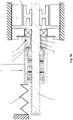
- FIG. 19 shows a longitudinal section of an actuator in the cage 10, the double loop spring (coil spring 1) is integrated, wherein the cage 10 against rotation on the bearing carrier housing / housing 5 of an efficiency-optimized spindle drive, here a PWG 6 is fixed.
- the Doppelschlingfeder thus prevents a relative movement between two mutually rotationally free parts (hub / shaft). This is particularly necessary in actuators that are driven by an axial force but not self-locking, but in case of failure (power failure) must hold the position.
- the functionality is as follows: If the hub 9 is rotated relative to the shaft 8 (driven by a drive motor, preferably electric motor 7) against the winding direction of the coil spring 1, the first region A of the double wrap spring is radially pressed into the hub 9 and locked, at the same time, the second region B2 dragged on the shaft 8 - the second area B indicates the lower drag torque, this is the preferred direction of rotation to work against the axial load F (for example, to open a clutch).
- the second area B2 is locked on the shaft 8 and supports the twisting moment
- the first area A of the double wrap spring is operated to open, but can support a drag torque which is greater than the restoring moment of the axial force.
- provision is prevented, in particular in the event of a fault.
- the drive motor must work against the drag torque of spring range A (assisted by the return torque of the axial load).
- the helical spring acting as a double wrap spring thus serves for the first time as a securing element against unintentional opening of the clutch in the event of a fault, because it is used as a friction element.
- a sufficiently large frictional torque in the closing direction and a very small frictional torque in the opening direction are provided.
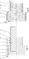
- FIG. 20 Another embodiment of the invention is disclosed in FIG. 20 shown on a longitudinal section of an actuator, in which the two regions having coil spring 1 (designed as a wrap spring first region A and designed as a torsion spring second region B1) between the outer diameter of the ring gear 11 and the inner diameter of a two-part sleeve 12 is arranged.
- the sleeve 12 is connected to the planet 6.2 receiving planet carrier 6.3, which mesh with the spindle 2, and has different areas of the inner diameter.
- a first region 12.1 has a smaller inner diameter which matches the first region A (wrap spring) and a second region 12.2 has a larger inner diameter which is adapted to the second region B1 (torsion spring) of the helical spring 1.
- the second end 1.2 which is formed on the second region B1, is angled radially outwardly and rotatably coupled to the second portion 20.2 of the sleeve 20.
- the ring gear 11 is seated axially between two thrust bearings 6.4 and is set via an axial bearing ring 6.5.
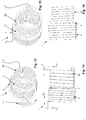
- FIG. 21 is a three-dimensional representation gem.
- the areas 12.1, 12.2 are connected to each other like a housing, wherein the area 12.2 has a radially outwardly facing recess 12.3, in which the torsionsfeder worne second end 1.2 of the coil spring is mounted rotationally fixed.
- FIG. 22 is a three-dimensional representation gem.
- FIG. 21 shown without sleeve 12, from which the different diameter ranges of the coil spring 1 in the form of the first region A, which is designed as a wrap spring and the second region B1 is formed as a torsion spring, can be seen.
- the second end 1.2 of the coil spring 1 engages in the recess 12.3 of the sleeve 12 to this rotation.
- Centric in the PWG the spindle is running 2.
- a three-dimensional representation of the ring gear 11 shows FIG. 23 , On whose non-designated outer diameter sits the coil spring 1 (not shown here), roll in the inner diameter of the planets also not shown here.
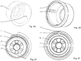
- FIG. 24 and FIG. 25 is a schematic representation of the first part of the sleeve 12.1 with a hinged spring (first area A) in the front view.
- the first part 12.1 of the sleeve 12 has similar to the spring cup 3 in Figure 7/8 a stop 12.4 for the radially outwardly angled first end 1.1 of the coil spring 1. Between the end 1.1 of the wrap spring and the stop 12.4 a torsion angle ⁇ is formed.
- FIG. 26 shows a three-dimensional representation of a second part of the sleeve 12.2 with the radially outwardly facing recess 12.3.
- FIG. 27 is apparent from a schematic diagram of the second part 12.2 of the sleeve 12, that in the recess 12.3, the radially outwardly facing second end 1.1 of the second region B1, the coil spring, 1 acts as a torsion spring is rotatably mounted.
- the first half 12.1 of the sleeve 12 has a stop 12.4 for the first end 1.1, which is spaced in the installed state to this first end 1.1 at an angle ⁇ in the closing direction of the wrap spring (first region A).
- the second sleeve 12.2 know a recess 12.3, in which the second end 1.2 is hung rotationally.
- the ring gear 11 has a cylindrical portion on which the first portion A (wrap spring) of the coil spring 1 is installed with a bias / interference.
- the second area B1 of the spring (torsion spring area) must have space radially outwardly and inwardly for twisting to the surrounding components (sleeve 12 and ring gear 11) in order to fulfill their function.
- the mode of action is the following:
- the low drag torque in the opening direction affects the efficiency of the PWG 6 only slightly.
- the wrap spring area first area A
- the wrap spring area is dragged by friction due to interference (between ring gear 11 and first area A) (reverse direction) and the second area B1 in the form of the torsion spring between ring gear 11 and planet carrier 6.3 twisted until restoring moment (due to the load) and torsion spring moment are in equilibrium.
- the second region B2 (Torsionsfeder Scheme) is further twisted until the first end reaches the stop 12.4 in the first half 12.1 of the sleeve 12 and the ring gear 11 slips in the coil spring 1. (Motor drive torque> as torsional moment until stop)
- the helical spring 1 can also be suspended on the ring gear 11, in which case the stop 12. 4 for the first end 1. 1 must also be mounted on the ring gear 11 or a component that is torsion-proof therewith.
- the cylindrical region (friction region) is then to be arranged in the sleeve 12, as will be described below with reference to a further variant.
- This second friction can not be achieved by the restoring force of the clutch alone all the way, by means of a motor, this force can be overcome by an intended axial stop for spring in the first sleeve part can be reached from a certain angle of rotation then a simpler provision by means of the motor become.
- the helical spring 1 has a first region A formed as a wrap spring and a second region B1 formed as a wrap spring.
- the first region A is in operative connection with the inner diameter of the first part 24.1 of the sleeve 24, the second region B1 is in operative connection with the outer diameter of the ring gear 11.
- the sleeve 12 is rotatably connected to the planet 6.2 receiving planet carriers 6.3.
- the planet 6.2 mesh with the spindle 2 and the ring gear 11 is seated between the two thrust bearings 6.4.
- FIG. 29 is a three-dimensional representation gem.
- the areas 12.1, 12.2 are also connected to each other like a box and form in the connection area a radially outwardly facing collar 12.5, which is encompassed by a sheet metal clamp 13.
- FIG. 30 shows an actuator with an efficiency-optimized spindle drive in the form of a PWG 6 according to Figure 28/29 that is similar to in FIG. 19 is constructed and has an integrated coil spring 1 in the form of a double wrap.
- the actuator operates force or torque controlled.
- the first region A of the wrap spring has an interference to a cylindrical portion of the ring gear 12 and is mounted on this frictionally engaged.
- a second region B2 of the wrap spring knows an interference to a cylindrical portion of the sleeve (functionally assigned to the planet carrier) and is installed in this frictionally engaged.
- the advantage of this variant is that a rotational assignment of the double wrap spring to the surrounding components is not necessary.
- a clutch is preferably actuated by an axial movement of the PWG, in which the rotational movement of the spindle is converted into an axial movement.
- the sleeve 12 of the PWG (which, for example, has a radially outwardly pointing shoulder performs during a rotational movement of the spindle an axial movement against the load of the plate spring tongues and actuates them.
Landscapes
- Engineering & Computer Science (AREA)
- General Engineering & Computer Science (AREA)
- Mechanical Engineering (AREA)
- Physics & Mathematics (AREA)
- Electromagnetism (AREA)
- Mechanical Operated Clutches (AREA)
- Transmission Devices (AREA)
- Springs (AREA)
Claims (9)
- Ensemble comprenant un système de frottement avec au moins deux pièces pouvant tourner l'une par rapport à l'autre, en particulier pour l'actionnement d'un embrayage d'un véhicule, dans lequel un ressort hélicoïdal (1) influençant un rendement ou un frottement lors d'une rotation relative des pièces est disposé entre les pièces pouvant tourner l'une par rapport à l'autre, dans lequel l'ensemble peut être au moins un composant d'une transmission et/ou d'un actionneur, et le ressort hélicoïdal (1), qui forme au moins localement un ressort enroulé, est un ressort enroulé simple ou un ressort enroulé double ou un ressort de torsion enroulé et présente une première région (A), une deuxième région (B1/B2) et une région de transition,
caractérisé en ce que les régions du ressort enroulé ou du ressort enroulé double ou du ressort de torsion enroulé sont enroulées en une bande et sont ainsi connectées les unes aux autres dans la région de transition (C) et en ce que la bande est torsadée dans la région de transition (C) et par conséquent la section transversale de la bande dans la première région (A) présente une première orientation et dans la deuxième région (B1/B2) présente une orientation tournée par rapport à celle-ci. - Ensemble comprenant un système de frottement selon la revendication 1, caractérisé en ce que le ressort hélicoïdal (1) est en liaison active avec une première pièce et avec une deuxième pièce disposée- de façon rotative
ou- de façon rotative et déplaçable axialementpar rapport à la première pièce. - Ensemble comprenant un système de frottement selon une des revendications 1 et 2, caractérisé en ce que la première pièce est disposée radialement à l'intérieur de la deuxième pièce et est éventuellement décalée axialement et- le ressort enroulé ou- le ressort enroulé double ou- le ressort de torsion enroulése trouve entre la première et la deuxième pièces et est relié par une première extrémité (1.1) sans rotation ou par frottement à la première pièce et par une deuxième extrémité (1.2) par frottement à la deuxième pièce.
- Ensemble comprenant un système de frottement selon l'une quelconque des revendications 1 à 3, caractérisé en ce que le ressort hélicoïdal (1) présente les caractéristiques suivantes:- une première région (A) agissant comme ressort enroulé (formule d'Eytelwein) avec la première extrémité (1.1), dans lequel un frottement ou une précontrainte constante ou variable peut être produit(e) dans la première région (A) pour obtenir un frottement,- une deuxième région (B1) agissant comme ressort de torsion avec la deuxième extrémité (1.2),- une région de transition (C), qui relie l'une à l'autre la première région (A) et la deuxième région (B1).
- Ensemble comprenant un système de frottement selon l'une quelconque des revendications 1 à 3, caractérisé en ce que le ressort hélicoïdal (1) réalisé en ressort enroulé double présente les caractéristiques suivantes:- une première région (A) agissant comme ressort enroulé (formule d'Eytelwein) avec une première extrémité émoussée (1.2), dans lequel un frottement ou une précontrainte/interférence (a1) par rapport à la deuxième pièce peut être produite dans la première région (A) sous la forme d'un moyeu (9)/arbre creux/alésage pour obtenir un frottement,- une deuxième région (B2) agissant comme ressort enroulé avec une deuxième extrémité émoussée (1.2), avec une précontrainte/interférence (a2) par rapport à la première pièce sous la forme d'un arbre (8),- une région de transition (C), qui relie l'une à l'autre la première région (A) et la deuxième région (B2).
- Ensemble comprenant un système de frottement selon l'une quelconque des revendications 1 à 5, caractérisé en ce qu'il est intégré dans une transmission par vis à rouleaux planétaires/PWG (6) actionnable par un entraînement ou dans une transmission d'un autre type, de telle manière qu'un frottement dépendant du sens de rotation soit, au moyen de entre la première pièce et la deuxième pièce, légèrement accru lorsque l'actionneur entraîne contre une charge ou nettement accru lorsque la charge entraîne, afin de garder une PWG (6)/transmission non autobloquante en cas de défaut/panne de l'entraînement ou afin de réduire ou d'éviter un courant de maintien.
- Ensemble comprenant un système de frottement selon l'une quelconque des revendications 1 à 6, caractérisé en ce que le ressort enroulé ou le ressort enroulé double ou le ressort de torsion enroulé est disposé entre un élément rotatif d'une PWG [transmission par vis à rouleaux planétaires] (6) ou d'une autre transmission et une partie de l'actionneur fixe par rapport au carter ou entre deux éléments de la PWG (6) ou d'une autre transmission pouvant tourner l'un par rapport à l'autre avec des vitesses différentes.
- Ensemble comprenant un système de frottement selon la revendication 7, caractérisé en ce que le ressort enroulé ou le ressort enroulé double ou le ressort de torsion enroulé- est disposé entre une broche (2) de la PWG (6) pouvant être entraînée en rotation par l'entraînement = première pièce et une pièce/cuvette de ressort (3) fixe par rapport au châssis/carter = deuxième pièceou- est disposé entre une broche (2) de la PWG (6) pouvant être entraînée en rotation par l'entraînement = première pièce et une cuvette de ressort (3) fixe en rotation/par rapport au châssis fixée à un carter de la PWG = deuxième pièce,ou- est intégré dans la PWG (6) entre deux pièces de la PWG (6) pouvant tourner l'une par rapport à l'autre.
- Ensemble comprenant un système de frottement selon la revendication 8, caractérisé en ce que le ressort enroulé ou le ressort enroulé double ou le ressort de torsion enroulé est disposé entre un diamètre extérieur d'une couronne dentée (11) engrenant avec les satellites de la PWG (6) = première pièce et un diamètre intérieur d'un manchon (12) entourant la PWG (6) dans la région de la couronne dentée (11) = deuxième pièce.
Applications Claiming Priority (3)
| Application Number | Priority Date | Filing Date | Title |
|---|---|---|---|
| DE102013219862 | 2013-10-01 | ||
| PCT/DE2014/200480 WO2015048961A2 (fr) | 2013-10-01 | 2014-09-18 | Ensemble comprenant un système de frottement |
| EP14789987.6A EP3052826B1 (fr) | 2013-10-01 | 2014-09-18 | Ensemble comprenant un système de frottement |
Related Parent Applications (2)
| Application Number | Title | Priority Date | Filing Date |
|---|---|---|---|
| EP14789987.6A Division EP3052826B1 (fr) | 2013-10-01 | 2014-09-18 | Ensemble comprenant un système de frottement |
| EP14789987.6A Division-Into EP3052826B1 (fr) | 2013-10-01 | 2014-09-18 | Ensemble comprenant un système de frottement |
Publications (2)
| Publication Number | Publication Date |
|---|---|
| EP3232076A1 EP3232076A1 (fr) | 2017-10-18 |
| EP3232076B1 true EP3232076B1 (fr) | 2019-01-02 |
Family
ID=51830171
Family Applications (2)
| Application Number | Title | Priority Date | Filing Date |
|---|---|---|---|
| EP17166199.4A Active EP3232076B1 (fr) | 2013-10-01 | 2014-09-18 | Module comprenant un dispositif de friction |
| EP14789987.6A Active EP3052826B1 (fr) | 2013-10-01 | 2014-09-18 | Ensemble comprenant un système de frottement |
Family Applications After (1)
| Application Number | Title | Priority Date | Filing Date |
|---|---|---|---|
| EP14789987.6A Active EP3052826B1 (fr) | 2013-10-01 | 2014-09-18 | Ensemble comprenant un système de frottement |
Country Status (7)
| Country | Link |
|---|---|
| US (1) | US10247253B2 (fr) |
| EP (2) | EP3232076B1 (fr) |
| JP (1) | JP6622191B2 (fr) |
| KR (1) | KR102267897B1 (fr) |
| CN (1) | CN105579726B (fr) |
| DE (1) | DE112014004531A5 (fr) |
| WO (1) | WO2015048961A2 (fr) |
Families Citing this family (26)
| Publication number | Priority date | Publication date | Assignee | Title |
|---|---|---|---|---|
| WO2015081951A1 (fr) * | 2013-12-06 | 2015-06-11 | Schaeffler Technologies AG & Co. KG | Actionneur comprenant une vis à rouleaux planétaires (pwg) |
| DE102015217164B4 (de) | 2014-09-11 | 2022-03-24 | Schaeffler Technologies AG & Co. KG | Baugruppe mit einer Reibeinrichtung |
| DE102015220920B4 (de) | 2014-12-15 | 2023-02-16 | Schaeffler Technologies AG & Co. KG | Baugruppe mit einer Reibeinrichtung |
| DE102015207082B4 (de) * | 2015-04-20 | 2017-07-06 | Schaeffler Technologies AG & Co. KG | Aktor mit einer Reibeinrichtung unter Verwendung eines Schlingfederelementes |
| DE102015207391B4 (de) * | 2015-04-23 | 2016-11-10 | Schaeffler Technologies AG & Co. KG | Aktor mit einem Planetenwälzgewindetrieb (PWG) |
| DE102015207642B4 (de) * | 2015-04-27 | 2017-07-06 | Schaeffler Technologies AG & Co. KG | Aktor mit Planetenwälzgewindetrieb |
| US10024415B2 (en) | 2015-11-02 | 2018-07-17 | Gates Corporation | Isolating decoupler |
| KR102658355B1 (ko) * | 2015-11-13 | 2024-04-18 | 섀플러 테크놀로지스 아게 운트 코. 카게 | 액추에이터 |
| DE102016214711A1 (de) * | 2016-08-09 | 2018-02-15 | Schaeffler Technologies AG & Co. KG | Doppelschlingfeder, Rotationseinrichtung und zu aktuierendes System |
| WO2018036589A1 (fr) * | 2016-08-23 | 2018-03-01 | Schaeffler Technologies AG & Co. KG | Double ressort enroulé, dispositif de rotation et système devant être actionné |
| JP6632504B2 (ja) * | 2016-10-03 | 2020-01-22 | 株式会社ミツバ | 動力伝達機構、アクチュエータ、および車両用アクチュエータ |
| DE102016221884A1 (de) | 2016-11-08 | 2018-05-09 | Schaeffler Technologies AG & Co. KG | Doppelschlingfeder, Rotationseinrichtung und zu aktuierendes System |
| DE102018112329B4 (de) | 2017-07-12 | 2020-06-04 | Schaeffler Technologies AG & Co. KG | Verfahren zur betrieblichen Ermittlung einer der Blockstellungen eines hydraulisch gedämpften Riemenspanners |
| US10384877B2 (en) * | 2017-12-08 | 2019-08-20 | General Kinematics Corporation | Spring assembly with transverse attachment site |
| DE102018104095A1 (de) | 2017-12-12 | 2019-06-13 | Schaeffler Technologies AG & Co. KG | Planetenwälzgewindetrieb, Aktuator und Ausrücksystem |
| US10711871B2 (en) * | 2018-01-26 | 2020-07-14 | Schaeffler Technologies AG & Co. KG | Axially compact linear actuator drive arrangement |
| SE543096C2 (en) * | 2018-07-19 | 2020-10-06 | Borgwarner Sweden Ab | An electrical actuator comprising a latching mechanism, a vehicle and a clutch comprising the actuator |
| DE102018131525A1 (de) * | 2018-12-10 | 2020-06-10 | Schaeffler Technologies AG & Co. KG | Antriebsstrang mit einer Mehrzahl von Teilsträngen für ein Kraftfahrzeug |
| DE102019102857A1 (de) | 2019-02-05 | 2020-08-06 | Brose Fahrzeugteile Se & Co. Kommanditgesellschaft, Bamberg | Antriebsstrang |
| JP7190412B2 (ja) * | 2019-09-25 | 2022-12-15 | 日立Astemo株式会社 | ディスクブレーキ |
| CN110961862B (zh) * | 2019-10-30 | 2020-12-18 | 西安远方航空技术发展有限公司 | 进气道测量耙中阻尼环的加工方法 |
| DE102019134250B3 (de) * | 2019-12-13 | 2020-11-26 | Schaeffler Technologies AG & Co. KG | Lageranordnung mit integrierter Doppelschlingfeder; sowie Aktor |
| DE102020105716C5 (de) | 2020-03-03 | 2024-08-29 | Edscha Engineering Gmbh | Stellantrieb mit einer Drehmomentbegrenzungsvorrichtung |
| AT523901B1 (de) * | 2020-06-12 | 2022-07-15 | Ktm Ag | Selbstsichernder Vorspannring für Federbeine |
| US20230405228A1 (en) * | 2020-11-20 | 2023-12-21 | Shl Medical Ag | Torsion spring mechanism for medicament delivery device, and medicament delivery device comprising said mechanism |
| CN115430998B (zh) * | 2022-09-21 | 2023-04-07 | 杭州富春弹簧有限公司 | 一种双涡卷弹簧生产工艺 |
Family Cites Families (28)
| Publication number | Priority date | Publication date | Assignee | Title |
|---|---|---|---|---|
| US2510653A (en) * | 1946-06-07 | 1950-06-06 | Marquette Metal Products Co | Detachable coupling |
| US3242696A (en) * | 1963-10-29 | 1966-03-29 | Kaplan Joseph | Multiple spring slip element |
| NL7509268A (nl) | 1974-08-30 | 1976-03-02 | Siemens Ag | Inrichting voor het begrenzen van het draaimo- ment voor twee draairichtingen. |
| US4246991A (en) * | 1978-04-26 | 1981-01-27 | Lear Siegler, Inc. | Linear motion mechanism with means for preventing back forces |
| US4364286A (en) * | 1980-02-15 | 1982-12-21 | The Rotor Tool Company | Bi-directional speed reducing mechanism |
| JPS59101018U (ja) * | 1982-12-27 | 1984-07-07 | 本田技研工業株式会社 | ラツプスプリングクラツチ |
| US4527683A (en) | 1983-03-22 | 1985-07-09 | Eaton Corporation | Torque limiting coil clutch and automatic slack adjuster utilizing same |
| USRE33514E (en) * | 1984-01-06 | 1991-01-08 | American Assembly Tools, Inc. | Adjustable torque limiting assembly |
| JPS6214446Y2 (fr) * | 1984-10-11 | 1987-04-13 | ||
| DE3739059A1 (de) | 1987-11-17 | 1989-05-24 | Deutsche Forsch Luft Raumfahrt | Vorrichtung zur umwandlung einer drehbewegung in eine axialbewegung |
| US5287949A (en) * | 1988-03-04 | 1994-02-22 | Nhk Spring Co., Ltd. | Shaft locking device |
| CN1054797C (zh) * | 1995-01-31 | 2000-07-26 | 日立工机株式会社 | 螺钉拧紧装置和离合器机构 |
| JP3676479B2 (ja) * | 1995-01-31 | 2005-07-27 | 日立工機株式会社 | ねじ締め装置及びクラッチ機構 |
| US5983743A (en) * | 1997-04-03 | 1999-11-16 | Dresser Industries, Inc. | Actuator assembly |
| JP2002337062A (ja) * | 2001-03-14 | 2002-11-26 | Daijiro Nakamura | 回転出力装置 |
| US20070137966A1 (en) * | 2004-02-27 | 2007-06-21 | Borgwarner Inc. | Electrohydraulic clutch assembly |
| JP5008928B2 (ja) * | 2005-10-31 | 2012-08-22 | 三ツ星ベルト株式会社 | プーリ構造体 |
| JP2008019959A (ja) * | 2006-07-12 | 2008-01-31 | Ntn Corp | スプリングクラッチ |
| DE102007047394A1 (de) | 2006-10-26 | 2008-04-30 | Luk Lamellen Und Kupplungsbau Beteiligungs Kg | Torsionsschwingungsdämpfer |
| JP5057561B2 (ja) | 2007-01-29 | 2012-10-24 | 備前発条株式会社 | 限界荷重付き回転軸構造 |
| CN201377534Y (zh) | 2009-04-14 | 2010-01-06 | 无锡丰力弹簧有限公司 | 洗衣机离合器棘轮抱簧 |
| ITCR20090031A1 (it) * | 2009-07-30 | 2011-01-31 | Cge Services & Trading Srl | Organo di innesto con meccanismo di trasmissione del moto a molla elicoidale e innesco ad attrito |
| FR2948960B1 (fr) | 2009-08-06 | 2011-12-09 | Valeo Securite Habitacle | Actionneur a assistance a la fermeture pour serrure d'ouvrant de vehicule automobile et dispositif associe |
| EP2494228B1 (fr) | 2009-10-29 | 2014-07-02 | Schaeffler Technologies GmbH & Co. KG | Actionneur d'embrayage hydrostatique |
| US9097229B2 (en) * | 2010-06-14 | 2015-08-04 | Litens Automotive Partnership | Engine starter having clutch assembly for selective transmission of rotary power between a plate structure and a drive hub |
| DE102012209883A1 (de) | 2011-07-07 | 2013-01-10 | Schaeffler Technologies AG & Co. KG | Hebelsystem |
| WO2013112048A1 (fr) * | 2012-01-23 | 2013-08-01 | Dti Group B.V. | Dispositif de démarrage destiné à faire démarrer un moteur à combustion |
| JP7026652B2 (ja) * | 2019-02-27 | 2022-02-28 | 日立グローバルライフソリューションズ株式会社 | 冷蔵庫 |
-
2014
- 2014-09-18 JP JP2016519838A patent/JP6622191B2/ja active Active
- 2014-09-18 EP EP17166199.4A patent/EP3232076B1/fr active Active
- 2014-09-18 WO PCT/DE2014/200480 patent/WO2015048961A2/fr not_active Ceased
- 2014-09-18 CN CN201480053270.7A patent/CN105579726B/zh active Active
- 2014-09-18 US US15/022,773 patent/US10247253B2/en active Active
- 2014-09-18 KR KR1020167008341A patent/KR102267897B1/ko active Active
- 2014-09-18 DE DE112014004531.4T patent/DE112014004531A5/de not_active Withdrawn
- 2014-09-18 EP EP14789987.6A patent/EP3052826B1/fr active Active
Non-Patent Citations (1)
| Title |
|---|
| None * |
Also Published As
| Publication number | Publication date |
|---|---|
| DE112014004531A5 (de) | 2016-07-21 |
| US10247253B2 (en) | 2019-04-02 |
| US20160230814A1 (en) | 2016-08-11 |
| CN105579726A (zh) | 2016-05-11 |
| CN105579726B (zh) | 2019-03-01 |
| WO2015048961A2 (fr) | 2015-04-09 |
| EP3232076A1 (fr) | 2017-10-18 |
| KR20160065842A (ko) | 2016-06-09 |
| KR102267897B1 (ko) | 2021-06-23 |
| EP3052826B1 (fr) | 2017-08-16 |
| JP2016538487A (ja) | 2016-12-08 |
| EP3052826A2 (fr) | 2016-08-10 |
| WO2015048961A3 (fr) | 2015-11-26 |
| JP6622191B2 (ja) | 2019-12-18 |
Similar Documents
| Publication | Publication Date | Title |
|---|---|---|
| EP3232076B1 (fr) | Module comprenant un dispositif de friction | |
| DE102015217164B4 (de) | Baugruppe mit einer Reibeinrichtung | |
| DE112016005194B4 (de) | Aktor | |
| DE102015220920B4 (de) | Baugruppe mit einer Reibeinrichtung | |
| DE102010006392B3 (de) | Spannungswellengetriebe und Nockenwellenversteller mit Spannungswellengetriebe | |
| DE102014202060A1 (de) | Nockenwellenversteller und Verfahren zum Betrieb eines Nockenwellenverstellers | |
| DE10143386A1 (de) | Parksperre für ein Kraftfahrzeug | |
| DE102016113117A1 (de) | Elektrischer Stellantrieb und Stellgerät mit einem elektrischen Stellantrieb | |
| DE102019003546A1 (de) | Adapter für einen Antrieb und Antrieb | |
| DE102010056068A1 (de) | Planetengetriebe, Planet und Planetenrad für ein Planetengetriebe, Handantriebseinrichtung und Antrieb mit einem Planetengetriebe | |
| DE102019209470B4 (de) | Parksperrenanordnung mit Parksperrenrad und Torsionsdämpfer | |
| DE102015207391B4 (de) | Aktor mit einem Planetenwälzgewindetrieb (PWG) | |
| EP1816368B1 (fr) | Embrayage à ressort hélicoidal | |
| DE102015220680A1 (de) | Baugruppe mit einer Reibeinrichtung | |
| EP3504453B1 (fr) | Double ressort enroulé, dispositif de rotation et système devant être actionné | |
| DE102012205995A1 (de) | Schräg verzahntes Getriebe, elektrische Maschine | |
| DE102015204504B4 (de) | Baugruppe, insbesondere Aktor mit einer Reibeinrichtung | |
| DE10221625A1 (de) | Vorrichtung zur Kopplung einer Gehäuseanordnung einer Kopplungseinrichtung mit einer Rotoranordnung einer Elektromaschine | |
| WO2018086653A1 (fr) | Double ressort enroulé, dispositif à rotation et système destiné à être actionné | |
| DE102015204588B4 (de) | Aktor mit einer Reibeinrichtung unter Verwendung eines Schlingfederelementes und Verfahren zur Herstellung des Schlingfederelementes | |
| WO2018060221A1 (fr) | Mécanisme de commande muni d'une double roue dentée à roue libre en deux parties pour la protection mécanique de la transmission, et boîtier du mécanisme de commande | |
| DE102016214711A1 (de) | Doppelschlingfeder, Rotationseinrichtung und zu aktuierendes System | |
| DE102010018210A1 (de) | Vorrichtung zur Verstellung der Drehwinkellage einer Welle | |
| DE102015207082B4 (de) | Aktor mit einer Reibeinrichtung unter Verwendung eines Schlingfederelementes | |
| DE102011088904A1 (de) | Drehverbindung |
Legal Events
| Date | Code | Title | Description |
|---|---|---|---|
| PUAI | Public reference made under article 153(3) epc to a published international application that has entered the european phase |
Free format text: ORIGINAL CODE: 0009012 |
|
| STAA | Information on the status of an ep patent application or granted ep patent |
Free format text: STATUS: THE APPLICATION HAS BEEN PUBLISHED |
|
| AC | Divisional application: reference to earlier application |
Ref document number: 3052826 Country of ref document: EP Kind code of ref document: P |
|
| AK | Designated contracting states |
Kind code of ref document: A1 Designated state(s): AL AT BE BG CH CY CZ DE DK EE ES FI FR GB GR HR HU IE IS IT LI LT LU LV MC MK MT NL NO PL PT RO RS SE SI SK SM TR |
|
| STAA | Information on the status of an ep patent application or granted ep patent |
Free format text: STATUS: REQUEST FOR EXAMINATION WAS MADE |
|
| 17P | Request for examination filed |
Effective date: 20180418 |
|
| RBV | Designated contracting states (corrected) |
Designated state(s): AL AT BE BG CH CY CZ DE DK EE ES FI FR GB GR HR HU IE IS IT LI LT LU LV MC MK MT NL NO PL PT RO RS SE SI SK SM TR |
|
| RIC1 | Information provided on ipc code assigned before grant |
Ipc: F16D 28/00 20060101ALI20180525BHEP Ipc: F16D 13/50 20060101AFI20180525BHEP Ipc: F16D 13/08 20060101ALI20180525BHEP |
|
| GRAP | Despatch of communication of intention to grant a patent |
Free format text: ORIGINAL CODE: EPIDOSNIGR1 |
|
| STAA | Information on the status of an ep patent application or granted ep patent |
Free format text: STATUS: GRANT OF PATENT IS INTENDED |
|
| INTG | Intention to grant announced |
Effective date: 20180730 |
|
| GRAS | Grant fee paid |
Free format text: ORIGINAL CODE: EPIDOSNIGR3 |
|
| GRAA | (expected) grant |
Free format text: ORIGINAL CODE: 0009210 |
|
| STAA | Information on the status of an ep patent application or granted ep patent |
Free format text: STATUS: THE PATENT HAS BEEN GRANTED |
|
| AC | Divisional application: reference to earlier application |
Ref document number: 3052826 Country of ref document: EP Kind code of ref document: P |
|
| AK | Designated contracting states |
Kind code of ref document: B1 Designated state(s): AL AT BE BG CH CY CZ DE DK EE ES FI FR GB GR HR HU IE IS IT LI LT LU LV MC MK MT NL NO PL PT RO RS SE SI SK SM TR |
|
| REG | Reference to a national code |
Ref country code: GB Ref legal event code: FG4D Free format text: NOT ENGLISH |
|
| REG | Reference to a national code |
Ref country code: CH Ref legal event code: EP Ref country code: AT Ref legal event code: REF Ref document number: 1084760 Country of ref document: AT Kind code of ref document: T Effective date: 20190115 |
|
| REG | Reference to a national code |
Ref country code: IE Ref legal event code: FG4D Free format text: LANGUAGE OF EP DOCUMENT: GERMAN |
|
| REG | Reference to a national code |
Ref country code: DE Ref legal event code: R096 Ref document number: 502014010565 Country of ref document: DE |
|
| REG | Reference to a national code |
Ref country code: NL Ref legal event code: MP Effective date: 20190102 |
|
| REG | Reference to a national code |
Ref country code: LT Ref legal event code: MG4D |
|
| PG25 | Lapsed in a contracting state [announced via postgrant information from national office to epo] |
Ref country code: NL Free format text: LAPSE BECAUSE OF FAILURE TO SUBMIT A TRANSLATION OF THE DESCRIPTION OR TO PAY THE FEE WITHIN THE PRESCRIBED TIME-LIMIT Effective date: 20190102 |
|
| PG25 | Lapsed in a contracting state [announced via postgrant information from national office to epo] |
Ref country code: FI Free format text: LAPSE BECAUSE OF FAILURE TO SUBMIT A TRANSLATION OF THE DESCRIPTION OR TO PAY THE FEE WITHIN THE PRESCRIBED TIME-LIMIT Effective date: 20190102 Ref country code: NO Free format text: LAPSE BECAUSE OF FAILURE TO SUBMIT A TRANSLATION OF THE DESCRIPTION OR TO PAY THE FEE WITHIN THE PRESCRIBED TIME-LIMIT Effective date: 20190402 Ref country code: PL Free format text: LAPSE BECAUSE OF FAILURE TO SUBMIT A TRANSLATION OF THE DESCRIPTION OR TO PAY THE FEE WITHIN THE PRESCRIBED TIME-LIMIT Effective date: 20190102 Ref country code: LT Free format text: LAPSE BECAUSE OF FAILURE TO SUBMIT A TRANSLATION OF THE DESCRIPTION OR TO PAY THE FEE WITHIN THE PRESCRIBED TIME-LIMIT Effective date: 20190102 Ref country code: ES Free format text: LAPSE BECAUSE OF FAILURE TO SUBMIT A TRANSLATION OF THE DESCRIPTION OR TO PAY THE FEE WITHIN THE PRESCRIBED TIME-LIMIT Effective date: 20190102 Ref country code: PT Free format text: LAPSE BECAUSE OF FAILURE TO SUBMIT A TRANSLATION OF THE DESCRIPTION OR TO PAY THE FEE WITHIN THE PRESCRIBED TIME-LIMIT Effective date: 20190502 Ref country code: SE Free format text: LAPSE BECAUSE OF FAILURE TO SUBMIT A TRANSLATION OF THE DESCRIPTION OR TO PAY THE FEE WITHIN THE PRESCRIBED TIME-LIMIT Effective date: 20190102 |
|
| PG25 | Lapsed in a contracting state [announced via postgrant information from national office to epo] |
Ref country code: LV Free format text: LAPSE BECAUSE OF FAILURE TO SUBMIT A TRANSLATION OF THE DESCRIPTION OR TO PAY THE FEE WITHIN THE PRESCRIBED TIME-LIMIT Effective date: 20190102 Ref country code: RS Free format text: LAPSE BECAUSE OF FAILURE TO SUBMIT A TRANSLATION OF THE DESCRIPTION OR TO PAY THE FEE WITHIN THE PRESCRIBED TIME-LIMIT Effective date: 20190102 Ref country code: BG Free format text: LAPSE BECAUSE OF FAILURE TO SUBMIT A TRANSLATION OF THE DESCRIPTION OR TO PAY THE FEE WITHIN THE PRESCRIBED TIME-LIMIT Effective date: 20190402 Ref country code: IS Free format text: LAPSE BECAUSE OF FAILURE TO SUBMIT A TRANSLATION OF THE DESCRIPTION OR TO PAY THE FEE WITHIN THE PRESCRIBED TIME-LIMIT Effective date: 20190502 Ref country code: GR Free format text: LAPSE BECAUSE OF FAILURE TO SUBMIT A TRANSLATION OF THE DESCRIPTION OR TO PAY THE FEE WITHIN THE PRESCRIBED TIME-LIMIT Effective date: 20190403 Ref country code: HR Free format text: LAPSE BECAUSE OF FAILURE TO SUBMIT A TRANSLATION OF THE DESCRIPTION OR TO PAY THE FEE WITHIN THE PRESCRIBED TIME-LIMIT Effective date: 20190102 |
|
| REG | Reference to a national code |
Ref country code: DE Ref legal event code: R097 Ref document number: 502014010565 Country of ref document: DE |
|
| PG25 | Lapsed in a contracting state [announced via postgrant information from national office to epo] |
Ref country code: DK Free format text: LAPSE BECAUSE OF FAILURE TO SUBMIT A TRANSLATION OF THE DESCRIPTION OR TO PAY THE FEE WITHIN THE PRESCRIBED TIME-LIMIT Effective date: 20190102 Ref country code: EE Free format text: LAPSE BECAUSE OF FAILURE TO SUBMIT A TRANSLATION OF THE DESCRIPTION OR TO PAY THE FEE WITHIN THE PRESCRIBED TIME-LIMIT Effective date: 20190102 Ref country code: SK Free format text: LAPSE BECAUSE OF FAILURE TO SUBMIT A TRANSLATION OF THE DESCRIPTION OR TO PAY THE FEE WITHIN THE PRESCRIBED TIME-LIMIT Effective date: 20190102 Ref country code: AL Free format text: LAPSE BECAUSE OF FAILURE TO SUBMIT A TRANSLATION OF THE DESCRIPTION OR TO PAY THE FEE WITHIN THE PRESCRIBED TIME-LIMIT Effective date: 20190102 Ref country code: CZ Free format text: LAPSE BECAUSE OF FAILURE TO SUBMIT A TRANSLATION OF THE DESCRIPTION OR TO PAY THE FEE WITHIN THE PRESCRIBED TIME-LIMIT Effective date: 20190102 Ref country code: IT Free format text: LAPSE BECAUSE OF FAILURE TO SUBMIT A TRANSLATION OF THE DESCRIPTION OR TO PAY THE FEE WITHIN THE PRESCRIBED TIME-LIMIT Effective date: 20190102 Ref country code: RO Free format text: LAPSE BECAUSE OF FAILURE TO SUBMIT A TRANSLATION OF THE DESCRIPTION OR TO PAY THE FEE WITHIN THE PRESCRIBED TIME-LIMIT Effective date: 20190102 |
|
| PLBE | No opposition filed within time limit |
Free format text: ORIGINAL CODE: 0009261 |
|
| STAA | Information on the status of an ep patent application or granted ep patent |
Free format text: STATUS: NO OPPOSITION FILED WITHIN TIME LIMIT |
|
| PG25 | Lapsed in a contracting state [announced via postgrant information from national office to epo] |
Ref country code: SM Free format text: LAPSE BECAUSE OF FAILURE TO SUBMIT A TRANSLATION OF THE DESCRIPTION OR TO PAY THE FEE WITHIN THE PRESCRIBED TIME-LIMIT Effective date: 20190102 |
|
| 26N | No opposition filed |
Effective date: 20191003 |
|
| PG25 | Lapsed in a contracting state [announced via postgrant information from national office to epo] |
Ref country code: SI Free format text: LAPSE BECAUSE OF FAILURE TO SUBMIT A TRANSLATION OF THE DESCRIPTION OR TO PAY THE FEE WITHIN THE PRESCRIBED TIME-LIMIT Effective date: 20190102 |
|
| PG25 | Lapsed in a contracting state [announced via postgrant information from national office to epo] |
Ref country code: TR Free format text: LAPSE BECAUSE OF FAILURE TO SUBMIT A TRANSLATION OF THE DESCRIPTION OR TO PAY THE FEE WITHIN THE PRESCRIBED TIME-LIMIT Effective date: 20190102 |
|
| PG25 | Lapsed in a contracting state [announced via postgrant information from national office to epo] |
Ref country code: MC Free format text: LAPSE BECAUSE OF FAILURE TO SUBMIT A TRANSLATION OF THE DESCRIPTION OR TO PAY THE FEE WITHIN THE PRESCRIBED TIME-LIMIT Effective date: 20190102 |
|
| REG | Reference to a national code |
Ref country code: CH Ref legal event code: PL |
|
| PG25 | Lapsed in a contracting state [announced via postgrant information from national office to epo] |
Ref country code: LI Free format text: LAPSE BECAUSE OF NON-PAYMENT OF DUE FEES Effective date: 20190930 Ref country code: CH Free format text: LAPSE BECAUSE OF NON-PAYMENT OF DUE FEES Effective date: 20190930 Ref country code: LU Free format text: LAPSE BECAUSE OF NON-PAYMENT OF DUE FEES Effective date: 20190918 Ref country code: IE Free format text: LAPSE BECAUSE OF NON-PAYMENT OF DUE FEES Effective date: 20190918 |
|
| REG | Reference to a national code |
Ref country code: BE Ref legal event code: MM Effective date: 20190930 |
|
| PG25 | Lapsed in a contracting state [announced via postgrant information from national office to epo] |
Ref country code: BE Free format text: LAPSE BECAUSE OF NON-PAYMENT OF DUE FEES Effective date: 20190930 |
|
| GBPC | Gb: european patent ceased through non-payment of renewal fee |
Effective date: 20190918 |
|
| PG25 | Lapsed in a contracting state [announced via postgrant information from national office to epo] |
Ref country code: GB Free format text: LAPSE BECAUSE OF NON-PAYMENT OF DUE FEES Effective date: 20190918 |
|
| REG | Reference to a national code |
Ref country code: AT Ref legal event code: MM01 Ref document number: 1084760 Country of ref document: AT Kind code of ref document: T Effective date: 20190918 |
|
| PG25 | Lapsed in a contracting state [announced via postgrant information from national office to epo] |
Ref country code: FR Free format text: LAPSE BECAUSE OF NON-PAYMENT OF DUE FEES Effective date: 20190930 Ref country code: AT Free format text: LAPSE BECAUSE OF NON-PAYMENT OF DUE FEES Effective date: 20190918 |
|
| PG25 | Lapsed in a contracting state [announced via postgrant information from national office to epo] |
Ref country code: CY Free format text: LAPSE BECAUSE OF FAILURE TO SUBMIT A TRANSLATION OF THE DESCRIPTION OR TO PAY THE FEE WITHIN THE PRESCRIBED TIME-LIMIT Effective date: 20190102 |
|
| PG25 | Lapsed in a contracting state [announced via postgrant information from national office to epo] |
Ref country code: MT Free format text: LAPSE BECAUSE OF FAILURE TO SUBMIT A TRANSLATION OF THE DESCRIPTION OR TO PAY THE FEE WITHIN THE PRESCRIBED TIME-LIMIT Effective date: 20190102 Ref country code: HU Free format text: LAPSE BECAUSE OF FAILURE TO SUBMIT A TRANSLATION OF THE DESCRIPTION OR TO PAY THE FEE WITHIN THE PRESCRIBED TIME-LIMIT; INVALID AB INITIO Effective date: 20140918 |
|
| PG25 | Lapsed in a contracting state [announced via postgrant information from national office to epo] |
Ref country code: MK Free format text: LAPSE BECAUSE OF FAILURE TO SUBMIT A TRANSLATION OF THE DESCRIPTION OR TO PAY THE FEE WITHIN THE PRESCRIBED TIME-LIMIT Effective date: 20190102 |
|
| P01 | Opt-out of the competence of the unified patent court (upc) registered |
Effective date: 20230522 |
|
| PGFP | Annual fee paid to national office [announced via postgrant information from national office to epo] |
Ref country code: DE Payment date: 20251119 Year of fee payment: 12 |