EP3232080A1 - Feder-dämpfersystem aus mehreren hintereinander angeordneten feder-dämpferelementen - Google Patents
Feder-dämpfersystem aus mehreren hintereinander angeordneten feder-dämpferelementen Download PDFInfo
- Publication number
- EP3232080A1 EP3232080A1 EP17000498.0A EP17000498A EP3232080A1 EP 3232080 A1 EP3232080 A1 EP 3232080A1 EP 17000498 A EP17000498 A EP 17000498A EP 3232080 A1 EP3232080 A1 EP 3232080A1
- Authority
- EP
- European Patent Office
- Prior art keywords
- spring
- damper
- elements
- intermediate support
- guide
- Prior art date
- Legal status (The legal status is an assumption and is not a legal conclusion. Google has not performed a legal analysis and makes no representation as to the accuracy of the status listed.)
- Granted
Links
Images


Classifications
-
- F—MECHANICAL ENGINEERING; LIGHTING; HEATING; WEAPONS; BLASTING
- F16—ENGINEERING ELEMENTS AND UNITS; GENERAL MEASURES FOR PRODUCING AND MAINTAINING EFFECTIVE FUNCTIONING OF MACHINES OR INSTALLATIONS; THERMAL INSULATION IN GENERAL
- F16F—SPRINGS; SHOCK-ABSORBERS; MEANS FOR DAMPING VIBRATION
- F16F3/00—Spring units consisting of several springs, e.g. for obtaining a desired spring characteristic
- F16F3/08—Spring units consisting of several springs, e.g. for obtaining a desired spring characteristic with springs made of a material having high internal friction, e.g. rubber
- F16F3/087—Units comprising several springs made of plastics or the like material
- F16F3/0873—Units comprising several springs made of plastics or the like material of the same material or the material not being specified
- F16F3/0876—Units comprising several springs made of plastics or the like material of the same material or the material not being specified and of the same shape
Definitions
- the invention relates to a spring-damper system comprising a plurality of successively arranged spring-damper elements, which are guided along at least one guide element.
- the present invention is based on the problem to develop such a spring-damper system that works easily and safely and also consists of a few different but many similar components.
- the one or more guide elements are rigid guide profiles or bendable traction means.
- the respective spring-damper element is designed in the form of a structure damper.
- the outer edge of the cross section of a spring-damper element surrounds the one or more guide elements. Between the successively arranged spring-damper elements intermediate support elements are arranged.
- the spring-damper elements are lined up, for example, on a guide element alternately with special intermediate support elements. For example, when damped cushioning a vertically falling load, the lowest intermediate support element is stationary. Possibly. this intermediate support element is attached to the guide element or otherwise arranged in a fixed manner. About this intermediate support element, the remaining intermediate support elements, each spaced by a spring-damper element stacked. On the uppermost spring-damper element in turn is an intermediate support element. Alternatively, the lowermost and the uppermost intermediate support element can each be replaced by a special, adapted to the task and function End galement.
- the falling load slides along the guide member in the direction of gravity down to sit at the stroke end on the upper intermediate or end support member and push together the coupled or stacked spring-damper elements to absorb energy.
- the individual structure damper can hereby differ in both the geometric shape and the material properties in order to precisely fulfill a specific function in the combination.
- the Figures 1 and 2 show a spring-damper system with many successively arranged spring-damper elements (40). Between each two spring-damper elements (40) has a substantially disc-shaped intermediate support element (60) is inserted. About the intermediate support elements (60), the spring-damper elements (40) are mounted and guided in the embodiments of a guide element (10).
- guide elements (10) are smooth-walled guide rods each having a circular cross-section (18).
- the guide rods (10) are made of a stainless steel, for example. They can also have non-circular cross-sections, such as those found in a polygon prism or in a polygonal profile. Furthermore, rectangular cross sections, oval or elliptical cross sections, semi-circular cross sections or other cross sections are possible, which may possibly prevent twisting of the guided components.
- the guide rods (10) are generally rectilinear and dimensionally stable guide elements. However, they may also be curved along a two- or three-dimensional trajectory. However, the center line (19) of the guide rod (10) at any point has two tangents.
- the guide element (11) a wire rope, for example, a left-handed Gleichschlagseil according to DIN EN 12385-2.
- a wire rope for example, a left-handed Gleichschlagseil according to DIN EN 12385-2.
- compacted strands or semi or fully closed spiral cables may be used.
- wire rope (11) can also be a traction means in the form of a joint or link chain, e.g. a roller chain according to DIN ISO 1275, are used.
- a flat belt is conceivable as a traction means.
- the spring-damper elements (40, 50) are lined up one behind the other. After the FIGS. 1 to 3 . 7 . 10 . 15 and 18 for example, there are only five spring-damper elements (40, 50) in each case.
- the latter are designed as structural dampers. They belong to the group of axial dampers.
- the single structural damper (40, 50) has in the embodiments in undeformed state a length of eg 35.6 mm with a maximum outer diameter of 47 mm.
- the individual structural damper (40) has the shape of a tube with a barrel-shaped wall, cf. FIGS. 1 to 5 and 7 , Despite a variable along its longitudinal extent cross-section, its wall thickness varies - outside the front chamfers - along this longitudinal extent only in the 1-5 percent range.
- the longitudinal extent in this case runs along the center line (19) of the respective guide element (10, 11).
- the average wall thickness is for example 8.5 mm.
- the wall thickness measures eg 18 ⁇ 5% of the maximum diameter of the respective structure damper.
- the minimum diameter of the central StrukturdämpferausEnglishung - it is in each case in the immediate vicinity of the respective end face (41, 42) - is in the embodiments of the Figures 2 and 7 about 23.6 mm. Between the end faces (41, 42) extends in the central region outwardly curved inner recess (48), see. also FIGS. 4 and 5 ,
- the maximum diameter of the barrel-shaped outer wall (43) is about 1/3 of the undeformed structure damper length removed from the left end face (41).
- the radius of curvature is approximately 16.6 mm at this point.
- FIGS. 10 to 12 and 15 show a cup-like structure damper (50) having approximately a bell-shaped wall.
- a bottom disc (54) with a flat bottom surface (55), which is delimited in the region of the outer wall (53) by a waist (57) from the outer bell shape.
- the bottom disc (54) has a central bore (56) measuring, for example 14 mm.
- the geometry of the inner recess (58) of the structure damper (50) corresponds in the area the right end face (52) of the geometry of the inner recess (48) of the structure damper (40).
- the coarse outer dimensions, the wall thicknesses and the curvature ratios of the structural damper (50) correspond to those of the structural damper (40) in the region of a 1 to 5 percent deviation.
- the waist-like constriction (57) facilitates the folding of the pot wall under axial load.
- the structural damper is deformed for damping and cushioning - in a compression in the longitudinal direction of the center line (19) - in the axial and radial directions.
- the pot wall bulges outwards in the middle region, as a result of which the respective inner wall region folds together, cf. also FIG. 18 , However, the maximum deformed structural damper (40) is shown there. Large areas of the outer wall are applied to the large plate surfaces (62) of the intermediate support elements (60). Both in the undeformed and in the load-deformed state, the structural dampers (40, 50) do not contact the guide element or elements (10, 11).
- the material is used for the dampers (40, 50) on a copolyester-based thermoplastic elastomer (TPC) used, for example, Hytrel ®. Its hardness in Shore is between 40D and 55D. For example, the single structural damper absorbs approximately 52% of the load-trapping energy. The rest is used for springback. After each functional deformation, it regains its original, geometric shape.
- TPC copolyester-based thermoplastic elastomer
- the structural damper (40, 50) are arranged in the same direction one behind the other. They can also be positioned alternately along the respective guide element (10, 11), cf. FIG. 7 ,
- the spring-damper elements (40) are supported on both sides by intermediate support elements (60).
- the at its - normal to the center line (19) of the guide member (10) located - symmetrical centered component (60) consists of an example one-piece disc-shaped plate (61) on a both sides of the plate (61) projecting sliding sleeve (63) is formed.
- the axially oriented plate surfaces (62) shown here in plan can have a crown or a spherical curvature, wherein the convex side of the curvature faces the respectively adjacent structure damper (40, 50).
- the sliding sleeve (63) guided on the guide rod (10) with a clearance of 0.1 to 0.2 mm has e.g. with an outer diameter of 23.8 mm a length of 21.5 mm.
- the guide rod (10) itself here has an outer diameter of 14 mm.
- the bore (64) of the sliding sleeve (63) is finished.
- the plate (61) formed integrally on the sliding sleeve (63) has a wall thickness of e.g. 5 mm.
- the outer diameter of the plate (61) is dimensioned, for example, so that it is always greater than the maximum outer diameter of the single, maximum compressed structural damper (40, 50), see. FIG. 18 , In the latter case, the sliding sleeve end faces of the intermediate support elements (60) contact.
- the intermediate support elements (60) are made, for example, of a dimensionally stable plastic, such as e.g. ABS, or made of an iron or non-ferrous metal material.
- the structural damper (40) with the frontal areas of the inner recess sit - for example, slightly stretched under tension - on the respective radial outer wall (65) of the sliding sleeve (63). At the same time they lie with their end faces (41, 42) on the flat surfaces (62) of the plate (61).
- the intermediate support element (60) is shown with an incorporated angle groove (68).
- a part of the angle groove (68) forms a channel in the plate surface (62), while the other part is a groove in the sliding sleeve (63).
- the angle groove (68) prevents inter alia the building of a braking dynamic pressure in the interior (49) of the structural damper (40, 50) when pushed together.
- one angle groove (68) extends per intermediate support element (60).
- each intermediate support element side it is also possible for each intermediate support element side to have several angle grooves or channels for the ventilation of the interior spaces (49) of the structural dampers (40, 50).
- the central bores of the intermediate support elements (60) are replaced by recesses (67).
- These recesses (67) widen, according to the sectional view FIG. 3 , starting from the center of the component (60) to the sliding sleeve side faces increasingly on.
- the wall of the recess (67) is a doubly curved shell whose shape corresponds, for example, to a central region of a torus near the center.
- the in the plane of the drawing FIG. 3 The curvature located has a radius which is smaller than the radius of the wire curl minus the wire rope radius.
- FIG. 10 a spring-damper system is shown, in which instead of the structure damper (40), the structure damper (50) are used. Since, in the case of these structural dampers (50), the inner recesses have different inner diameters at the ends, It is necessary to use appropriately designed intermediate support elements (70).
- the illustrated intermediate support element (70) has a stepped sliding sleeve (73).
- the example, 10 mm short, left end of the sliding sleeve (73) is a short sliding sleeve tube (75), for example, has an outer diameter of 14 mm and into the bore (56) of the bottom plate (54) protrudes.
- the right end of the sliding sleeve (73) has a 12 mm long sliding sleeve tube (76) an outer diameter of 23.8 mm. At it, the left end portion of the inner recess (58) of the structure damper (50) is supported.
- the guide rod (10) has an outer diameter of 10 mm in this embodiment.
- the left outer structural damper (50) rests in FIG. 10 on an end support element (100).
- the end support element (100) is, for example, a disk whose central bore (101) surrounds the guide element (10) in a force-fitting manner, for example.
- a short sliding sleeve tube (75) is formed for positioning the structure damper (50).
- the right outer structural damper (50) abuts an end support member (110), e.g. also has the shape of a disc.
- a long sliding sleeve tube (76) is arranged on the right side, which engages in the large opening of the inner recess (58) of the structure damper (50).
- the central bore (111) of the end support member (110) sits with a clearance of 0.1 to 0.2 mm on the guide rod. At this End 400 is the - not shown here - to be mitigated or attenuated load.
- FIG. 7 a spring damping system is shown in which the structural dampers (40) are supported on intermediate support elements (80), which are comparable in terms of their symmetry and coarse dimensions with the intermediate support elements (60). Indeed have the intermediate support elements (80) in the region of the end faces (81, 82) of the sliding sleeve (63) integrally formed behind grip elements (86), cf.
- FIG. 9 For example, at the front edge, along the circumference, five elastic rear grip elements (86) are arranged.
- the sliding sleeve (63) theoretically each end a recess (83) with a flat collar surface (85).
- the recess (83) can be so much material over the entire sliding sleeve length in the end that there is a tubular end portion (84), which is 4 mm long with an outer diameter of 18 mm, for example. This preserves the length of the bore (64). Over the free end surfaces of the end portions (84), the intermediate support members (80) can contact each other at maximum compression of the spring-damper system.
- the individual engagement elements (86) are formed on both sides of the sliding sleeve (63) so that they project outwardly from the collar surface (85) on each side.
- the outer envelope surface of the detent elements (86) forms a truncated cone-shaped surface whose cone angle is e.g. 14.3 ⁇ 2 angular degrees.
- the tip of the imaginary cone lies on the other side of the plate (61).
- the individual rear grip elements (86) are separated from one another by narrow slots (87) which extend to the collar surface (85). Since the rear grip elements (86) have a wall thickness smaller than the radial extent of the recess (83), it measures e.g. 2 mm, is located radially between the end portion (84) and the rear grip elements (86) has an annular channel (88) with a rectangular or trapezoidal cross-section.
- the intermediate support elements (80) and (90) are used to create elastic rear grip elements, for example made of a polyamide, a polyethylene or a comparable elastic material manufactured. Possibly. the material may be enriched at least in some areas with glass or carbon fibers.
- FIG. 7 For example, five structural damper (40) are shown, which are arranged in addition to the alternate arrangement also axially backlash and biased on the guide element (10).
- the guide rod (10) has at its left end a shaft collar (12) on which the first intermediate support element (80) rests.
- the left shaft end has a larger diameter than the central region of the guide rod (10) on which the intermediate support elements (80) can slide.
- a cup-shaped end support element (120) is arranged in front of the right outer structural damper (40).
- the bottom (121) and the left side of this end support member (120) correspond to the intermediate support members (80) used herein.
- a support tube (122) is integrally formed or attached.
- the inner diameter of the support tube (122) is greater than the maximum outer diameter of a locking ring (127) latched onto the guide rod (10).
- a structure damper (40) Between the retaining ring (127) and the shaft collar (12) sit the structure damper (40) under a predetermined bias.
- the locking ring (127) sits on the guide rod (10) in a conventional annular groove (13).
- a circumferential notch relief groove (14) whose in FIG. 7 illustrated cross-section is designed semicircular.
- the constriction by the Kerbentlastungsnut (14) is greater than that of the annular groove (13), so that the notch effect latter is largely eliminated.
- the load to be absorbed or dampened acts on the right-side end face (125) of the end support element (120). If the cushioning to the mutual contacting of the intermediate support members (80) may be required, the minimum length of the support tube (122) is calculated from the product, which consists of the number of structural damper (40) and the maximum free distance between two adjacent sliding sleeves (63) lies.
- FIG. 15 will be one with FIG. 10 partially comparable spring-damper system shown.
- the rear grip elements (86) of the respective left slide sleeve end faces (81) are in FIG ). They correspond with respect to their structural design largely from FIG. 9 known grip elements (86).
- Each right sides of the stepped sliding sleeves (73) are, for example, six elements which protrude at the theoretically plan collar surface (95) of the stepped or shortened sliding sleeve (73) substantially in the axial direction.
- the waistband (95) is oriented normal to the centerline (19).
- the outer envelope surface of the rear grip elements (96) also forms a frustoconical surface whose cone angle measures, for example, 14.3 ⁇ 2 angular degrees.
- the tip of the imaginary cone lies on the other side of the plate (61).
- the individual rear grip elements (96) are separated from one another by narrow slots (87) which extend to the collar surface (95).
- the free ends of the radially outwardly spring-loaded rear grip elements (96) are planar partial surfaces (98) of a planar contact envelope surface over which - in the case of block dampers (50) - the respective right-side sliding sleeve end of an intermediate support element (90) contacts the left side slide sleeve end of the adjacent intermediate support member (90).
- the wall thickness of the individual rear grip elements (96) is constant, for example, so that the inner surfaces (99) of the rear grip elements (96) do not contact the guide rod (10).
- the guide elements (10, 11) are shown only as an example horizontally. Of course, the guide elements can also be positioned vertically or askew in space.
Landscapes
- Engineering & Computer Science (AREA)
- General Engineering & Computer Science (AREA)
- Mechanical Engineering (AREA)
- Vibration Dampers (AREA)
- Vibration Prevention Devices (AREA)
- Buildings Adapted To Withstand Abnormal External Influences (AREA)
Abstract
Description
- Die Erfindung betrifft ein Feder-Dämpfersystem aus mehreren hintereinander angeordneten Feder-Dämpferelementen, die entlang mindestens eines Führungselements geführt sind.
- Zum Dämpfen und Abfedern von Maschinenschlitten, die horizontal, vertikal oder schräg im Raum gelagert und geführt sind, werden oft einfache, wartungsarme und ggf. wetterfeste Systeme benötigt. Solche Systeme sollen beispielsweise auch im Aufzugsbau, in manntragenden Körben von Fassadenreinigungsvorrichtungen oder in Sicherungsvorrichtungen von Industriekletterern verwendbar sein.
- Aus dem Lehrbuch "Decker, Maschinenelemente; Gestaltung und Berechnung" des Carl Hanser Verlags, München, 12. Auflage, Seiten 251 und 252, ist das Hintereinanderschalten von Schraubendruckfedern unter Verwendung von zwischen den Schraubendruckfedern angeordneten Platten bekannt.
- Aus der noch unveröffentlichten
DE 10 2009 012 684 A1 ist ein Rückstoßdämpfungssystem für eine Schulterstütze bekannt, bei dem zwei Feder-Dämpferelemente hintereinander angeordnet sind. - Der vorliegenden Erfindung liegt die Problemstellung zugrunde, ein derartiges Feder-Dämpfersystem zu entwickeln, das einfach und sicher funktioniert und zudem aus wenigen verschiedenen aber vielen gleichartigen Bauteilen besteht.
- Diese Problemstellung wird mit den Merkmalen des Hauptanspruchs gelöst. Dabei sind das oder die Führungselemente starre Führungsprofile oder biegbare Zugmittel. Das jeweilige Feder-Dämpferelement ist in Form eines Strukturdämpfers ausgebildet. Der Außenrand des Querschnitts eines Feder-Dämpferelements umschließt das oder die Führungselemente. Zwischen den hintereinander angeordneten Feder-Dämpferelementen sind Zwischenstützelemente angeordnet.
- Die Feder-Dämpferelemente werden z.B. auf einem Führungselement wechselweise mit speziellen Zwischenstützelementen aufgereiht. Beispielsweise beim gedämpften Abfedern einer vertikal fallenden Last, liegt das unterste Zwischenstützelement ortsfest auf. Ggf. ist dieses Zwischenstützelement am Führungselement befestigt oder in sonstiger Weise fest angeordnet. Über diesem Zwischenstützelement stapeln sich die restlichen Zwischenstützelemente, jeweils durch ein Feder-Dämpferelement voneinander beabstandet. Auf dem obersten Feder-Dämpferelement liegt wiederum ein Zwischenstützelement auf. Alternativ können das unterste und das oberste Zwischenstützelement jeweils durch ein spezielles, an die Aufgabe und Funktion angepasstes Endstützelement ersetzt werden.
- Die fallende Last gleitet entlang dem Führungselement in Schwerkraftrichtung nach unten, um am Hubende am oberen Zwischen- oder Endstützelement aufzusitzen und die gekoppelten bzw. gestapelten Feder-Dämpferelemente energieabsorbierend zusammenzuschieben.
- Der größte Teil der Energie der Last wird in den in Reihe geschalteten Strukturdämpfern in Federenergie und Wärme umgewandelt. Die Wärme entsteht durch innere Reibung im Material des Strukturdämpfers. Die kurzzeitig gespeicherte Federenergie der gekoppelten Strukturdämpfer wird nach dem Abfedern der Last durch ein teilweises Dekomprimieren der Strukturdämpfer in Form eines geringfügigen Anhebens der Last wieder freigegeben. Wird die Last von den Strukturdämpfern weggefahren, so entspannen sich letztere vollständig. Dies ist möglich, da die Zwischenstützelemente und ggf. mindestens eines der Endstützelemente reibungsarm auf dem Führungselement geführt sind.
- Da das Material des einzelnen Strukturdämpfers weitgehend inkompressibel ist, kann dieser beim Dämpfen nur seine Gestalt aber nicht sein Volumen ändern.
- Anstelle der in den Ausführungsbeispielen verwendeten gleichartigen Strukturdämpfer pro System können auch mehrere verschiedenartige Strukturdämpfer entlang eines Führungselements angeordnet werden. Die einzelnen Strukturdämpfer können sich hierbei sowohl in der geometrischen Gestalt als auch in den Werkstoffeigenschaften unterscheiden, um in der Kombination eine bestimmte Funktion präzise zu erfüllen.
- Auch ist es möglich, Strukturdämpfer, deren Querschnittsbreite z.B. größer ist als deren Qüerschnittstiefe, an zwei parallelen, zueinander beabstandeten Führungselementen zu führen. Strukturdämpfer mit großen Querschnitten können ferner an drei oder mehr parallelen Führungselementen geführt werden. In der Regel ist hierbei der Querschnitt des Strukturdämpfers immer größer als die Summe der Einzelquerschnitte der verwendeten Führungselemente.
- Weitere Einzelheiten der Erfindung ergeben sich aus den Unteransprüchen und der nachfolgenden Beschreibung mindestens einer schematisch dargestellten Ausführungsform.
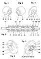
- Figur 1:
- perspektivische Ansicht eines Feder-Dämpfersystems mit hintereinander angeordneten Strukturdämpfern;
- Figur 2:
- Längsschnitt zu
Figur 1 ; - Figur 3:
- Längsschnitt zu
Figur 1 , jedoch mit ungeradem und/oder flexiblem Führungselement; - Figur 4:
- schräge Vorderansicht eines Strukturdämpfers nach
Figur 1 ; - Figur 5:
- schräge Rückansicht zu
Figur 4 ; - Figur 6:
- perspektivische Ansicht eines Zwischenstützelements nach
Figur 1 ; - Figur 7:
- Längsschnitt eines Feder-Dämpfersystems mit strukturdämpferhintergreifenden Zwischenstützelementen;
- Figur 8:
- perspektivische Ansicht eines Zwischenstützelements mit Be- und Entlüftungskerbe für das System nach
Figur 1 ; - Figur 9:
- perspektivische Ansicht eines Zwischenstützelements mit Hintergriffselementen nach
Figur 7 ; - Figur 10:
- Längsschnitt eines Feder-Dämpfersystems mit taillierten Strukturdämpfern;
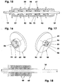
- Figur 11:
- schräge Vorderansicht eines Strukturdämpfers nach
Figur 10 und15 ; - Figur 12:
- schräge Rückansicht zu
Figur 11 ; - Figur 13:
- perspektivische Ansicht eines Zwischenstützelements von schräg vorn nach
Figur 10 ; - Figur 14:
- perspektivische Ansicht eines Zwischenstützelements von schräg hinten nach
Figur 10 ; - Figur 15:
- Längsschnitt eines Feder-Dämpfersystems mit taillierten Strukturdämpfern und Zwischenstützelementen mit Hintergriffselementen;
- Figur 16:
- perspektivische Ansicht eines Zwischenstützelements nach
Figur 15 von schräg vorn; - Figur 17:
- perspektivische Ansicht eines Zwischenstützelements nach
Figur 15 von schräg hinten; - Figur 18:
- Längsschnitt der auf Block zusammengeschobenen Feder-Dämpfersystemelemente des Systems nach
Figur 2 . - Die
Figuren 1 und 2 zeigen ein Feder-Dämpfersystem mit vielen hintereinander angeordneten Feder-Dämpferelementen (40). Zwischen je zwei Feder-Dämpferelementen (40) ist ein im Wesentlichen scheibenförmiges Zwischenstützelement (60) eingefügt. Über die Zwischenstützelemente (60) sind die Feder-Dämpferelemente (40) in den Ausführungsbeispielen an einem Führungselement (10) gelagert und geführt. - Die in den
Figuren 1, 2 ,10 ,15 und 18 gezeigten Führungselemente (10) sind glattwandige Führungsstangen mit jeweils kreisrundem Querschnitt (18). Die Führungsstangen (10) sind beispielsweise aus einem nichtrostenden Stahl gefertigt. Sie können auch unrunde Querschnitte haben, wie sie z.B. bei einem Vieleckprisma oder bei einem Polygonprofil zu finden sind. Ferner sind Rechteckquerschnitte, Oval- oder Ellipsenquerschnitte, Halbrundquerschnitte oder andere Querschnitte möglich, die ggf. ein Verdrehen der geführten Bauteile verhindern können. - Die Führungsstangen (10) sind in der Regel geradlinige und formsteife Führungselemente. Sie können jedoch auch entlang einer zwei- oder dreidimensionalen Bahnkurve gekrümmt sein. Allerdings hat die Mittellinie (19) der Führungsstange (10) an keiner Stelle zwei Tangenten.
- Nach
Figur 3 ist das Führungselement (11) ein Drahtseil, z.B. ein linksgängiges Gleichschlagseil nach DIN EN 12385-2. Vorzugsweise können verdichtete Litzen oder halb- oder vollverschlossene Spiralseile verwendet werden. - Anstelle eines Drahtseiles (11) kann auch ein Zugmittel in Form einer Gelenk- oder Gliederkette, z.B. eine Rollenkette nach DIN ISO 1275, eingesetzt werden. Auch ein Flachriemen ist als Zugmittel denkbar.
- Auf dem Führungselement (10, 11) sind u.a. die Feder-Dämpferelemente (40, 50) hintereinander aufgereiht. Nach den
Figuren 1 bis 3 ,7 ,10 ,15 und 18 sind es jeweils nur beispielhaft fünf Feder-Dämpferelemente (40, 50). Letztere sind als Strukturdämpfer ausgebildet. Sie gehören zur Gruppe der Axialdämpfer. Der einzelne Strukturdämpfer (40, 50) hat in den Ausführungsbeispielen im unverformten Zustand eine Länge von z.B. 35,6 mm bei einem maximalen Außendurchmesser von 47 mm. - Der einzelne Strukturdämpfer (40) hat die Form eines Rohres mit tonnenförmiger Wandung, vgl.
Figuren 1 bis 5 und7 . Trotz eines entlang seiner Längsausdehnung veränderlichen Querschnitts, variiert seine Wandstärke - außerhalb der stirnseitigen Anfasungen - entlang dieser Längsausdehnung nur im 1 bis 5-Prozentbereich. Die Längsausdehnung verläuft hierbei entlang der Mittellinie (19) des jeweiligen Führungselements (10, 11). - Die mittlere Wandstärke liegt z.B. bei 8,5 mm. Die Wandstärke misst z.B. 18 ± 5 % des maximalen Durchmessers des jeweiligen Strukturdämpfers. Der minimale Durchmesser der zentralen Strukturdämpferausnehmung - er liegt jeweils in unmittelbarer Nähe der jeweiligen Stirnseite (41, 42) - beträgt bei den Ausführungsbeispielen der
Figuren 2 und7 ca. 23,6 mm. Zwischen den Stirnseiten (41, 42) erstreckt sich die im mittleren Bereich nach außen gewölbte Innenausnehmung (48), vgl. auchFiguren 4 und 5 . - Der maximale Durchmesser der tonnenförmigen Außenwandung (43) ist von der linken Stirnseite (41) ca. 1/3 der unverformten Strukturdämpferlänge entfernt. Der Krümmungsradius beträgt an dieser Stelle ca. 16,6 mm.
- Die
Figuren 10 bis 12 und15 zeigen einen topfartigen Strukturdämpfer (50), der näherungsweise eine glockenförmige Wandung aufweist. Im Bereich der linken Stirnseite (51) hat er eine Bodenscheibe (54) mit einer planen Bodenfläche (55), die sich im Bereich der Außenwandung (53) durch eine Taille (57) von der äußeren Glockenform abgrenzt. Die Bodenscheibe (54) hat eine zentrale Bohrung (56), die z.B. 14 mm misst. Die Geometrie der Innenausnehmung (58) des Strukturdämpfers (50) entspricht im Bereich der rechten Stirnseite (52) der Geometire der Innenausnehmung (48) des Strukturdämpfers (40). Die groben Außenmaße, die Wandstärken und die Krümmungsverhältnisse des Strukturdämpfers (50) entsprechen im Bereich einer 1 bis 5 prozentigen Abweichung denen des Strukturdämpfers (40). - Die taillenartige Einschnürung (57) erleichtert das Zusammenfalten der Topfwandung unter axialer Belastung. Der Strukturdämpfer wird zur Dämpfung und Abfederung - bei einer Kompression in Längsrichtung der Mittellinie (19) - in Axial- und Radialrichtung verformt. Die Topfwandung beult im mittleren Bereich nach außen, wodurch sich der jeweilige Innenwandungbereich zusammenfaltend aneinanderlegt, vgl. auch
Figur 18 . Allerdings ist dort der maximal verformte Strukturdämpfer (40) dargestellt. Große Bereiche der Außenwandung legen sich an den großen Tellerflächen (62) der Zwischenstützelemente (60) an. Sowohl im unverformten als auch im unter Last verformten Zustand kontaktieren die Strukturdämpfer (40, 50) nicht das oder die Führungselemente (10, 11). - Als Werkstoff wird für die Strukturdämpfer (40, 50) ein auf CoPolyester basierter thermoplastischer Elastomer (TPC) verwendet, z.B. Hytrel ®. Seine Härte in Shore liegt zwischen 40D und 55D. Der einzelne Strukturdämpfer absorbiert beispielsweise ca. 52% der Lastabfangenergie. Der Rest wird für das Rückfedern benutzt. Nach jeder funktionsbedingten Verformung erlangt er wieder seine ursprüngliche, konstruktionsbedingte geometrische Form.
- In den
Figuren 1 bis 3 ,10 ,15 und 18 sind die Strukturdämpfer (40, 50) gleichsinnig hintereinander angeordnet. Sie sind entlang des jeweiligen Führungselements (10, 11) auch wechselweise positionierbar, vgl.Figur 7 . - Gemäß
Figur 2 stützen sich die Feder-Dämpferelemente (40) beidseitig an Zwischenstützelementen (60) ab. Das zu seiner - normal zur Mittellinie (19) des Führungselements (10) gelegenen - Mittelebene symmetrisch gestaltete Bauteil (60) besteht aus einem z.B. einteiligen, scheibenförmigen Teller (61), der an einer beidseits des Tellers (61) überstehenden Gleithülse (63) angeformt ist. Ggf. können die hier plan dargestellten axialorientierten Tellerflächen (62) eine Balligkeit oder eine sphärische Krümmung aufweisen, wobei die konvexe Seite der Krümmung dem jeweils anliegenden Strukturdämpfer (40, 50) zugewandt ist. - Die auf der Führungsstange (10) mit einem Spiel von 0,1 bis 0,2 mm geführte Gleithülse (63) hat z.B. bei einem Außendurchmesser von 23,8 mm eine Länge vom 21,5 mm. Die Führungsstange (10) selbst hat hier einen Außendurchmesser von 14 mm. Die Bohrung (64) der Gleithülse (63) ist feinbearbeitet. Der mittig auf der Gleithülse (63) angeformte Teller (61) hat bei einem Außendurchmesser von 59 mm eine Wandstärke von z.B. 5 mm.
- Der Außendurchmesser des Tellers (61) ist beispielsweise so bemessen, dass er immer größer ist als der maximale Außendurchmesser des einzelnen, maximal gestauchten Strukturdämpfers (40, 50), vgl.
Figur 18 . In letzterem Fall kontaktieren sich die Gleithülsenstirnseiten der Zwischenstützelemente (60). - Die Zwischenstützelemente (60) werden beispielsweise aus einem formsteifen Kunststoff, wie z.B. ABS, oder aus einem Eisen- oder Buntmetallwerkstoff gefertigt.
- Im zusammengebauten Feder-Dämpfersystem sitzen die Strukturdämpfer (40) mit den stirnseitennahen Bereichen der Innenausnehmung - z.B. geringfügig gedehnt unter Zugspannung - auf der jeweiligen radialen Außenwandung (65) der Gleithülse (63). Zugleich liegen sie mit ihren Stirnseiten (41, 42) an den Planflächen (62) der Teller (61) an.
- In
Figur 8 ist das Zwischenstützelement (60) mit einer eingearbeiteten Winkelnut (68) dargestellt. Ein Teil der Winkelnut (68) bildet einen Kanal in der Tellerfläche (62), während der andere Teil eine Nut in der Gleithülse (63) ist. Die Winkelnut (68) verhindert u.a. das Aufbauen eines bremsenden Staudrucks im Innenraum (49) der Strukturdämpfer (40, 50) bei dessen Zusammenschieben. Prinzipiell reicht pro Zwischenstützelement (60) eine Winkelnut (68). Es können aber auch pro Zwischenstützelementseite mehrere Winkelnuten oder Kanäle für die Be- und Entlüftung der Innenräume (49) der Strukturdämpfer (40, 50) angeordnet werden. - Für den Anwendungsfall nach
Figur 3 werden die zentralen Bohrungen der Zwischenstützelemente (60) durch Ausnehmungen (67) ersetzt. Diese Ausnehmungen (67) weiten sich, gemäß der Schnittdarstellung nachFigur 3 , ausgehend von der Mitte des Bauteils (60) zu den gleithülsenseitigen Stirnflächen zunehmend auf. Die Wandung der Ausnehmung (67) ist eine doppelt gekrümmte Schale, deren Form z.B. einem zentrumsnahen Teilbereich eines Torus entspricht. Die in der Zeichnungsebene derFigur 3 gelegene Krümmung hat einen Radius, der kleiner ist als der Radius der Drahtseilkrümmung abzüglich des Drahtseilradius. - Soll das Führungselement ein Zugmittel z.B. in Form einer Gelenk- oder Gliederkette sein, wird die Ausnehmung des Zwischenstützelements (60, 70, 80, 90) an die Querschnittsform des Zugmittels und an den kleinsten Krümmungsradius des Führungselements (10, 11) angepasst. Ein derartiges Zugmittel krümmt sich in der Regel nur in einer Ebene. Findet das dämpfende Zusammenschieben der Feder-Dämpferelemente (40, 50) auf einem Abschnitt einer Kreisbahn statt, können die Stirnseiten (81, 82) gewölbt ausgeführt werden. Die Wölbung (78), vgl.
Figur 3 , hat die Form eines Zylindermantelabschnitts, dessen Mittellinie die Zeichnungsebene derFigur 3 senkrecht schneidet und zugleich auf der Verlängerung der Mittellinie (69, 79) der jeweiligen Gleithülse (63, 73) liegt. Die Flächenpressung zwischen zwei einander kontaktierenden Stirnseiten (81, 82) ist minimal, wenn der Krümmungsradius der Wölbung (78) gleich oder geringfügig kleiner ist als der aus der folgenden Formel berechnete Radius "r": - Der Radius "r" basiert auf dem Krümmungsradius "R" der Mittellinie (19), dem Durchmesser "d" und der Wandstärke "b" des Tellers (61). Über die Hilfsgrößen "p" und "q" wird "r" ermittelt


- Wird anstelle der Kette ein im Raum gekrümmtes Stahlseil benutzt, wird der Zylindermantelabschnitt durch eine sphärische Krümmung ersetzt. Die Bedingungen für den Radius "r" bleiben erhalten.
- In
Figur 10 wird ein Feder-Dämpfersystem gezeigt, bei dem anstelle der Strukturdämpfer (40) die Strukturdämpfer (50) eingesetzt werden. Da bei diesen Strukturdämpfern (50) die Innenausnehmung endseitig unterschiedlich große Innendurchmesser haben, ist es erforderlich, entsprechend passend gestaltete Zwischenstützelemente (70) zu verwenden. Das gezeigte Zwischenstützelement (70) hat dabei eine gestufte Gleithülse (73). Das z.B. 10 mm kurze, linke Ende der Gleithülse (73) ist ein kurzes Gleithülsenrohr (75), das z.B. einen Außendurchmesser von 14 mm hat und in die Bohrung (56) der Bodenscheibe (54) hineinragt. Das rechte Ende der Gleithülse (73) hat als 12 mm langes Gleithülsenrohr (76) einen Außendurchmesser von 23,8 mm. An ihm stützt sich der linke Endbereich der Innenausnehmung (58) des Strukturdämpfers (50) ab. - Die Führungsstange (10) hat in diesem Ausführungsbeispiel einen Außendurchmesser von 10 mm. Der linke, äußere Strukturdämpfer (50) stützt sich in
Figur 10 an einem Endstützelement (100) ab. Das Endstützelement (100) ist z.B. eine Scheibe, dessen zentrale Bohrung (101) das Führungselement (10) z.B. kraftschlüssig umgibt. An ihm ist zur Positionierung des Strukturdämpfers (50) ein kurzes Gleithülsenrohr (75) angeformt. - Am rechten, äußeren Strukturdämpfer (50) liegt ein Endstützelement (110) an, das z.B. ebenfalls die Form einer Scheibe hat. Allerdings ist hier rechtsseitig ein langes Gleithülsenrohr (76) angeordnet, das in die große Öffnung der Innenausnehmung (58) des Strukturdämpfers (50) eingreift. Die zentrale Bohrung (111) des Endstützelements (110) sitzt mit einem Spiel von 0,1 bis 0,2 mm auf der Führungsstange. An diesem Endstützelement (110) steht die - hier nicht dargestellt - abzufedernde bzw. abzudämpfende Last an.
- In
Figur 7 wird ein Feder-Dämpfungssystem gezeigt, bei dem die Strukturdämpfer (40) sich an Zwischenstützelementen (80) abstützen, die bezüglich ihrer Symmetrie und groben Abmessungen mit den Zwischenstützelementen (60) vergleichbar sind. Allerdings haben die Zwischenstützelemente (80) im Bereich der Stirnseiten (81, 82) der Gleithülse (63) angeformte Hintergriffselemente (86), vgl.Figur 9 . Beispielsweise sind am stirnseitigen Rand, entlang dem Umfang, fünf elastische Hintergriffselemente (86) angeordnet. Dazu weist die Gleithülse (63) endseitig theoretisch jeweils eine Eindrehung (83) mit einer planen Bundfläche (85) auf. Die Eindrehung (83) lässt über die gesamte Gleithülsenlänge im Endbereich so viel Material stehen, dass dort ein rohrförmiger Endabschnitt (84) entsteht, der bei einem Außendurchmesser von 18 mm z.B. 4 mm lang ist. Dadurch bleibt die Länge der Bohrung (64) erhalten. Über die freien Stirnflächen der Endabschnitte (84) können sich die Zwischenstützelemente (80) bei maximaler Kompression des Feder-Dämpfersystems gegenseitig kontaktieren. - Im radial äußeren Bereich der planen Bundfläche (85) sind die einzelnen Hintergriffselemente (86) auf beiden Seiten der Gleithülse (63) so angeformt, dass sie pro Seite von der Bundfläche (85) aus nach außen abstehen. Die äußere Hüllfläche der Hintergriffselemente (86) bildet eine kegelstumpfmantelförmige Fläche, deren Kegelwinkel z.B. 14,3 ± 2 Winkelgrade misst. Die Spitze des gedachten Kegels liegt jeweils auf der anderen Seite des Tellers (61). Die einzelnen Hintergriffselemente (86) sind durch schmale Schlitze (87) voneinander getrennt, die sich bis zur Bundfläche (85) erstrecken. Da die Hintergriffelemente (86) eine Wandstärke haben, die kleiner ist als die radiale Ausdehnung der Eindrehung (83), sie misst z.B. 2 mm, befindet sich radial zwischen dem Endabschnitt (84) und den Hintergriffselementen (86) ein Ringkanal (88) mit einem rechteckigen oder trapezförmigen Querschnitt.
- Die Zwischenstützelemente (80) und (90) werden zur Schaffung elastischer Hintergriffselemente z.B. aus einem Polyamid, einem Polyethylen oder aus einem vergleichbar elastischen Werkstoff gefertigt. Ggf. kann der Werkstoff zumindest bereichsweise mit Glas- oder Kohlefasern angereichert sein.
- In
Figur 7 sind beispielsweise fünf Strukturdämpfer (40) gezeigt, die neben der wechselweisen Anordnung auch noch axial spielfrei und vorgespannt auf dem Führungselement (10) angeordnet sind. Dazu hat die Führungsstange (10) an ihrem linken Ende einen Wellenbund (12), an dem das erste Zwischenstützelement (80) anliegt. Das linke Wellenende hat einen größeren Durchmesser als der mittlere Bereich der Führungsstange (10), auf dem die Zwischenstützelemente (80) gleiten können. Vor dem rechts außen liegenden Strukturdämpfer (40) ist anstelle eines Zwischenstützelementes (80) ein topfförmiges Endstützelement (120) angeordnet. Der Boden (121) und die linke Seite dieses Endstützelements (120) entsprechen den hier verwendeten Zwischenstützelementen (80). Allerdings ist an der rechten Seite des Tellers (61) ein Stützrohr (122) angeformt oder befestigt. Der Innendurchmesser des Stützrohres (122) ist größer als der maximale Außendurchmesser eines auf der Führungsstange (10) eingerasteten Sicherungsrings (127). Zwischen dem Sicherungsring (127) und dem Wellenbund (12) sitzen die Strukturdämpfer (40) unter einer vorgegebenen Vorspannung. - Der Sicherungsring (127) sitzt auf der Führungsstange (10) in einer üblichen Ringnut (13). In Belastungsrichtung vor der Ringnut (13) befindet sich eine umlaufende Kerbentlastungsnut (14), deren in
Figur 7 dargestellter Querschnitt halbkreisförmig gestaltet ist. Die Einschnürung durch die Kerbentlastungsnut (14) ist größer als die der Ringnut (13), so dass die Kerbwirkung letzterer weitgehend eliminiert wird. - Im Belastungsfall nach
Figur 7 wirkt die abzufedernde bzw. abzudämpfende Last auf die rechtsseitige Stirnfläche (125) des Endstützelementes (120). Soll die Abfederung bis zum gegenseitigen Kontaktieren der Zwischenstützelemente (80) erforderlich sein, errechnet sich die minimale Länge des Stützrohres (122) aus dem Produkt, das aus der Anzahl der Strukturdämpfer (40) und dem maximalen freien Abstand besteht, der zwischen zwei benachbarten Gleithülsen (63) liegt. - In
Figur 15 wird ein mitFigur 10 teilweise vergleichbares Feder-Dämpfersystem dargestellt. Allerdings sind hier beide Stirnseiten (81, 82) der gestuften Gleithülse (73) der Zwischenstützelemente (90) mit die Strukturdämpfer (50) einhakenden Hintergriffselementen (86, 96) ausgestattet. Die Hintergriffselemente (86) der jeweils linken Gleithülsenstirnseiten (81) sind inFigur (16 ) gezeigt. Sie entsprechen bezüglich ihres konstruktiven Aufbaus weitgehend den ausFigur 9 bekannten Hintergriffselementen (86). - Bei den Hintergriffselementen (86) der - nach
Figur 15 - jeweils rechten Seiten der gestuften Gleithülsen (73) handelt es sich um z.B. sechs Elemente, die an der theoretisch planen Bundfläche (95) der gestuften bzw. verkürzten Gleithülse (73) im Wesentlichen in Axialrichtung abstehen. Die Bundfläche (95) ist normal zur Mittellinie (19) orientiert. Die äußere Hüllfläche der Hintergriffselemente (96) bildet auch hier eine kegelstumpfmantelförmige Fläche, deren Kegelwinkel z.B. 14,3 ± 2 Winkelgrade misst. Die Spitze des gedachten Kegels liegt jeweils auf der anderen Seite des Tellers (61). Die einzelnen Hintergriffselemente (96) sind durch schmale Schlitze (87) voneinander getrennt, die sich bis zur Bundfläche (95) erstrecken. Die freien Enden der radial nach außen aufgefederten Hintergriffselemente (96) sind plane Teilflächen (98) einer planen Kontakthüllfläche, über die - bei auf Block liegenden Strukturdämpfern (50) - das jeweils rechtsseitige Gleithülsenende des einen Zwischenstützelements (90) das linksseitige Gleithülsenende des danebenliegenden Zwischenstützelements (90) kontaktiert. - Die Wandstärke der einzelnen Hintergriffselemente (96) ist beispielsweise konstant, so dass die Innenflächen (99) der Hintergriffselemente (96) die Führungsstange (10) nicht kontaktieren.
- In den dargestellten Ausführungsbeispielen sind die Führungselemente (10, 11) nur beispielhaft horizontal dargestellt. Selbstverständlich können die Führungselemente auch vertikal oder windschief im Raum positioniert sein.
-
- 10
- Führungselement, Führungsstange, formsteif
- 11
- Führungselement, Drahtseil, flexibel
- 12
- Wellenbund
- 13
- Ringnut
- 14
- Kerbentlastungsnut
- 18
- Querschnittsform, Querschnitt
- 19
- Mittellinie
- 40
- Feder-Dämpferelemente, Dämpferglieder, Strukturdämpfer, Axialdämpfer, Dämpfer
- 41, 42
- Stirnseiten; links, rechts
- 43
- Außenwandung
- 48
- Innenausnehmung, Strukturdämpferausnehmung
- 49
- Innenraum
- 50
- Feder-Dämpferelemente mit Taille, Dämpferglieder, Strukturdämpfer, Axialdämpfer, Dämpfer
- 51, 52
- Stirnseiten; links, rechts
- 53
- Außenwandung
- 54
- Bodenscheibe
- 55
- Bodenfläche
- 56
- Bohrung, zentral
- 57
- Taille, Einschnürung
- 58
- Innenausnehmung
- 60
- Zwischenstützelemente, symmetrisch, Bauteil
- 61
- Teller
- 62
- Planfläche, Tellerfläche, Stirnseite
- 63
- Gleithülse
- 64
- Bohrung, zylindrisch, Ausnehmung
- 65
- Außenwandung, radial
- 67
- Ausnehmung, bereichsweise torusmantelförmig
- 68
- Winkelnut
- 69
- Mittellinie
- 70
- Zwischenstützelemente, asymmetrisch
- 73
- Gleithülse, gestuft
- 75
- Gleithülsenrohr, kurz, kleiner Außendurchmesser
- 76
- Gleithülsenrohr, lang, großer Außendurchmesser
- 78
- Wölbung, gestrichelt dargestellt
- 79
- Mittellinie
- 80
- Zwischenstützelemente mit Hintergriffen, symmetrisch,
- 81, 82
- Stirnseiten; links, rechts von (60, 70, 80, 90)
- 83
- Eindrehung
- 84
- Endabschnitt
- 85
- Bundfläche, plan
- 86
- Hintergriffselemente
- 87
- Schlitze
- 88
- Ringkanal
- 90
- Zwischenstützelemente mit Hintergriffen, asymmetrisch
- 95
- Bundfläche, plan
- 96
- Hintergriffselemente, klein
- 97
- Schlitze
- 98
- Teilflächen
- 99
- Innenflächen
- 100
- Endstützelement, links
- 101
- Bohrung, zentral
- 110
- Endstützelement, rechts
- 111
- Bohrung, zentral
- 120
- Endstützelement, topfförmig
- 121
- Boden
- 122
- Stützrohr
- 125
- Stirnfläche, Lastauflage
- 127
- Sicherungsring
Claims (10)
- Feder-Dämpfersystem aus mehreren hintereinander angeordneten Feder-Dämpferelementen (40, 50), die entlang mindestens eines Führungselements (10, 11) geführt sind,- wobei das oder die Führungselemente (10, 11) starre Führungsprofile oder biegbare Zugmittel sind,- wobei das jeweilige Feder-Dämpferelement (40, 50) in Form eines Strukturdämpfers ausgebildet ist,- wobei der Außenrand des Querschnitts eines Feder-Dämpferelements (40, 50) das oder die Führungselemente (10, 11) umschließt und- wobei zwischen den hintereinander angeordneten Feder-Dämpferelementen (40, 50) Zwischenstützelemente (60, 70, 80, 90) angeordnet sind.
- Feder-Dämpfersystem gemäß Anspruch 1, dadurch gekennzeichnet, dass zwischen zwei Feder-Dämpferelementen (40, 50) ein Zwischenstützelement (60, 70, 80, 90) angeordnet ist.
- Feder-Dämpfersystem gemäß Anspruch 1, dadurch gekennzeichnet, dass die Zwischenstützelemente (60, 70, 80, 90) an den Führungselementen (10, 11) gleitfähig geführt sind.
- Feder-Dämpfersystem gemäß Anspruch 1, dadurch gekennzeichnet, dass die freien Enden der endseitigen Feder-Dämpferelemente (40, 50) an Endstützelementen (100, 110) anliegen, deren den Feder-Dämpferelementen (40, 50) zugewandte geometrische Form der analogen Seite eines entsprechenden Zwischenstützelements (60, 70, 80, 90) entspricht.
- Feder-Dämpfersystem gemäß Anspruch 1, dadurch gekennzeichnet, dass das einzelne Zwischenstützelement (60, 70, 80, 90) einen Teller (61) hat, an dessen Stirnseiten (62) jeweils ein Feder-Dämpferelement (40, 50) anliegt.
- Feder-Dämpfersystem gemäß Anspruch 1, dadurch gekennzeichnet, dass das einzelne Zwischenstützelement (60, 70, 80, 90) eine Gleithülse (63, 73) hat, deren Bohrung (64) oder Ausnehmung (67) das jeweilige Führungselement (10, 11) kontaktiert und an dessen radialer Außenwandung (65) das jeweilige Feder-Dämpferelement (40, 50) zumindest bereichsweise anliegt.
- Feder-Dämpfersystem gemäß Anspruch 1, dadurch gekennzeichnet, dass das einzelne Feder-Dämpferelement (40, 50) aufgrund seiner Materialeigenschaften nach jeder funktionsbedingten Belastung in seine Ausgangslage zurückkehrt und somit auch ein Rückholsystem bildet.
- Feder-Dämpfersystem gemäß Anspruch 1, dadurch gekennzeichnet, dass das einzelne Feder-Dämpferelement (40, 50) eine rohr- und/oder topfförmige Gestalt hat und in der Hauptsache axial belastbar ist.
- Feder-Dämpfersystem gemäß Anspruch 1, dadurch gekennzeichnet, dass für das einzelne Feder-Dämpferelement (40, 50) ein auf einem CoPolyester basierender thermoplastischer Elastomer (TPC) verwendet wird, dessen Härte in Shore zwischen 40D und 55D liegt.
- Feder-Dämpfersystem gemäß Anspruch 6, dadurch gekennzeichnet, dass jede Gleithülse (63, 73) mindestens an einem Ende mindestens zwei elastisch federnde Hintergriffselemente (86, 96) aufweist.
Applications Claiming Priority (1)
| Application Number | Priority Date | Filing Date | Title |
|---|---|---|---|
| DE102016003607.9A DE102016003607B4 (de) | 2016-03-29 | 2016-03-29 | Feder-Dämpfersystem aus mehreren hintereinander angeordneten Feder-Dämpferelementen |
Publications (2)
| Publication Number | Publication Date |
|---|---|
| EP3232080A1 true EP3232080A1 (de) | 2017-10-18 |
| EP3232080B1 EP3232080B1 (de) | 2022-09-28 |
Family
ID=58544678
Family Applications (1)
| Application Number | Title | Priority Date | Filing Date |
|---|---|---|---|
| EP17000498.0A Active EP3232080B1 (de) | 2016-03-29 | 2017-03-27 | Feder-dämpfersystem aus mehreren hintereinander angeordneten feder-dämpferelementen |
Country Status (2)
| Country | Link |
|---|---|
| EP (1) | EP3232080B1 (de) |
| DE (1) | DE102016003607B4 (de) |
Cited By (1)
| Publication number | Priority date | Publication date | Assignee | Title |
|---|---|---|---|---|
| CN112555329A (zh) * | 2020-12-11 | 2021-03-26 | 苏州市通吉汽车零部件有限公司 | 一种具有耐压结构的减振器弹簧及其加工工艺 |
Citations (9)
| Publication number | Priority date | Publication date | Assignee | Title |
|---|---|---|---|---|
| BE355901A (de) * | 1928-11-17 | 1929-02-28 | Weydert Hubert Jules | |
| US2639141A (en) * | 1950-10-27 | 1953-05-19 | Perma Realty Co | Shock-absorbing mechanism |
| DE2734501A1 (de) * | 1977-07-30 | 1979-02-01 | Alpine Ag | Vorrichtung zur daempfung der laermabstrahlung bei der mechanischen bearbeitung von werkstuecken |
| US4200268A (en) * | 1977-06-17 | 1980-04-29 | Eduard Wiek | Shock-absorber |
| EP0019533A1 (de) * | 1979-05-11 | 1980-11-26 | Hutchinson-Mapa | Stossdämpfer |
| GB2079400A (en) * | 1980-07-04 | 1982-01-20 | Norde Suspensions Ltd | Suspension or damping unit |
| US20100059470A1 (en) * | 2008-09-10 | 2010-03-11 | Carlstedt Richard A | Railcar elastomeric spring |
| EP2184508A1 (de) * | 2007-08-01 | 2010-05-12 | Tancheng Huang | Elastomerstruktur |
| DE102009012684A1 (de) | 2009-03-13 | 2010-09-16 | Günther Zimmer | Rückstoßdämpfersystem für eine Schulterstütze |
Family Cites Families (7)
| Publication number | Priority date | Publication date | Assignee | Title |
|---|---|---|---|---|
| DE1003053B (de) * | 1953-10-12 | 1957-02-21 | Heinrich Ristenpart | Achsenfederung, insbesondere fuer Landfahrzeuge, vorzugsweise Kraftfahrzeuge |
| DE1120901B (de) * | 1958-12-06 | 1961-12-28 | Maschf Augsburg Nuernberg Ag | Federung zwischen einem Motor und dem Rahmen von Strassen- und Schienenfahrzeugen |
| US3677535A (en) * | 1970-08-24 | 1972-07-18 | Lord Corp | Axial suspension system that accommodate relative lateral movement |
| US3781058A (en) * | 1972-03-03 | 1973-12-25 | Int Harvester Co | Shock and vibration dampening mount assembly |
| US4198037A (en) * | 1976-12-28 | 1980-04-15 | Miner Enterprises, Inc. | Method of making polyester elastomer compression spring and resulting product |
| DE102008015552B4 (de) * | 2008-03-25 | 2011-02-10 | Siemens Aktiengesellschaft | Kompakt-Entkoppler-Modul |
| BE1020628A3 (fr) * | 2012-04-24 | 2014-02-04 | Vention Sprl E | Ressort de compression. |
-
2016
- 2016-03-29 DE DE102016003607.9A patent/DE102016003607B4/de not_active Expired - Fee Related
-
2017
- 2017-03-27 EP EP17000498.0A patent/EP3232080B1/de active Active
Patent Citations (9)
| Publication number | Priority date | Publication date | Assignee | Title |
|---|---|---|---|---|
| BE355901A (de) * | 1928-11-17 | 1929-02-28 | Weydert Hubert Jules | |
| US2639141A (en) * | 1950-10-27 | 1953-05-19 | Perma Realty Co | Shock-absorbing mechanism |
| US4200268A (en) * | 1977-06-17 | 1980-04-29 | Eduard Wiek | Shock-absorber |
| DE2734501A1 (de) * | 1977-07-30 | 1979-02-01 | Alpine Ag | Vorrichtung zur daempfung der laermabstrahlung bei der mechanischen bearbeitung von werkstuecken |
| EP0019533A1 (de) * | 1979-05-11 | 1980-11-26 | Hutchinson-Mapa | Stossdämpfer |
| GB2079400A (en) * | 1980-07-04 | 1982-01-20 | Norde Suspensions Ltd | Suspension or damping unit |
| EP2184508A1 (de) * | 2007-08-01 | 2010-05-12 | Tancheng Huang | Elastomerstruktur |
| US20100059470A1 (en) * | 2008-09-10 | 2010-03-11 | Carlstedt Richard A | Railcar elastomeric spring |
| DE102009012684A1 (de) | 2009-03-13 | 2010-09-16 | Günther Zimmer | Rückstoßdämpfersystem für eine Schulterstütze |
Cited By (2)
| Publication number | Priority date | Publication date | Assignee | Title |
|---|---|---|---|---|
| CN112555329A (zh) * | 2020-12-11 | 2021-03-26 | 苏州市通吉汽车零部件有限公司 | 一种具有耐压结构的减振器弹簧及其加工工艺 |
| CN112555329B (zh) * | 2020-12-11 | 2022-03-22 | 苏州市通吉汽车零部件有限公司 | 一种具有耐压结构的减振器弹簧及其加工工艺 |
Also Published As
| Publication number | Publication date |
|---|---|
| EP3232080B1 (de) | 2022-09-28 |
| DE102016003607B4 (de) | 2022-08-18 |
| DE102016003607A1 (de) | 2017-10-05 |
Similar Documents
| Publication | Publication Date | Title |
|---|---|---|
| DE3730393C2 (de) | Lenkwelle für Kraftfahrzeuge, bestehend aus axial ineinander verschieblichen Wellenteilen | |
| DE102013208003A1 (de) | Längseinsteller für einen Fahrzeugsitz und Fahrzeugsitz | |
| DE102008049799A1 (de) | Freilauf mit Innenstern | |
| EP2753842A1 (de) | Freilaufeinrichtung | |
| DE102015206618A1 (de) | Fliehkraftpendel | |
| EP2625442B1 (de) | Klemmrollenfreilauf für eine verstelleinrichtung in einem kraftfahrzeug | |
| DE102017123897A1 (de) | Fliehkraftpendel | |
| EP3232080B1 (de) | Feder-dämpfersystem aus mehreren hintereinander angeordneten feder-dämpferelementen | |
| DE102009025985A1 (de) | Biegedorn mit Ausrichtemitteln | |
| DE102009042166A1 (de) | Kugelrollenlager | |
| DE4222175A1 (de) | Wälzlagerkäfig | |
| DE102015209309B4 (de) | Freilauf | |
| DE102006044802A1 (de) | Kombiniertes Rollen-Kugellager | |
| DE102004014775A1 (de) | Mehrreihiges Schrägkugellager | |
| WO2016112887A1 (de) | Geräuschentkoppeltes lager für ein cvt-getriebe mit ovaler nut | |
| DE2257761A1 (de) | Waelzlagerkaefig | |
| DE2201437A1 (de) | Waelzlager-Freilaufkupplung | |
| WO2017045677A1 (de) | Drehmomentübertragungseinrichtung | |
| EP1956252A1 (de) | Längsverschiebeeinheit für Gelenkwellen | |
| WO2015003905A1 (de) | Verstellungsantrieb, insbesondere höhenverstellungsantrieb, eines fahrzeugsitzes mit einer fangvorrichtung | |
| EP3321538A1 (de) | Torsionsschwingungsdämpfer | |
| DE1202588B (de) | Kugelkaefig eines Gleichlaufdrehgelenkes | |
| DE102017114940A1 (de) | Rampenaktor sowie Kupplungseinrichtung mit Rampenaktor | |
| DE102015106330A1 (de) | Torsionsschwingungsdämpfungsvorrichtung | |
| DE102016123938A1 (de) | Fliehkraftpendeleinrichtung |
Legal Events
| Date | Code | Title | Description |
|---|---|---|---|
| PUAI | Public reference made under article 153(3) epc to a published international application that has entered the european phase |
Free format text: ORIGINAL CODE: 0009012 |
|
| STAA | Information on the status of an ep patent application or granted ep patent |
Free format text: STATUS: THE APPLICATION HAS BEEN PUBLISHED |
|
| AK | Designated contracting states |
Kind code of ref document: A1 Designated state(s): AL AT BE BG CH CY CZ DE DK EE ES FI FR GB GR HR HU IE IS IT LI LT LU LV MC MK MT NL NO PL PT RO RS SE SI SK SM TR |
|
| AX | Request for extension of the european patent |
Extension state: BA ME |
|
| STAA | Information on the status of an ep patent application or granted ep patent |
Free format text: STATUS: REQUEST FOR EXAMINATION WAS MADE |
|
| 17P | Request for examination filed |
Effective date: 20180416 |
|
| RBV | Designated contracting states (corrected) |
Designated state(s): AL AT BE BG CH CY CZ DE DK EE ES FI FR GB GR HR HU IE IS IT LI LT LU LV MC MK MT NL NO PL PT RO RS SE SI SK SM TR |
|
| STAA | Information on the status of an ep patent application or granted ep patent |
Free format text: STATUS: EXAMINATION IS IN PROGRESS |
|
| 17Q | First examination report despatched |
Effective date: 20191121 |
|
| GRAP | Despatch of communication of intention to grant a patent |
Free format text: ORIGINAL CODE: EPIDOSNIGR1 |
|
| STAA | Information on the status of an ep patent application or granted ep patent |
Free format text: STATUS: GRANT OF PATENT IS INTENDED |
|
| INTG | Intention to grant announced |
Effective date: 20220622 |
|
| GRAS | Grant fee paid |
Free format text: ORIGINAL CODE: EPIDOSNIGR3 |
|
| GRAA | (expected) grant |
Free format text: ORIGINAL CODE: 0009210 |
|
| STAA | Information on the status of an ep patent application or granted ep patent |
Free format text: STATUS: THE PATENT HAS BEEN GRANTED |
|
| AK | Designated contracting states |
Kind code of ref document: B1 Designated state(s): AL AT BE BG CH CY CZ DE DK EE ES FI FR GB GR HR HU IE IS IT LI LT LU LV MC MK MT NL NO PL PT RO RS SE SI SK SM TR |
|
| REG | Reference to a national code |
Ref country code: GB Ref legal event code: FG4D Free format text: NOT ENGLISH |
|
| REG | Reference to a national code |
Ref country code: CH Ref legal event code: EP |
|
| REG | Reference to a national code |
Ref country code: DE Ref legal event code: R096 Ref document number: 502017013846 Country of ref document: DE |
|
| REG | Reference to a national code |
Ref country code: AT Ref legal event code: REF Ref document number: 1521415 Country of ref document: AT Kind code of ref document: T Effective date: 20221015 |
|
| REG | Reference to a national code |
Ref country code: IE Ref legal event code: FG4D Free format text: LANGUAGE OF EP DOCUMENT: GERMAN |
|
| REG | Reference to a national code |
Ref country code: LT Ref legal event code: MG9D |
|
| PG25 | Lapsed in a contracting state [announced via postgrant information from national office to epo] |
Ref country code: SE Free format text: LAPSE BECAUSE OF FAILURE TO SUBMIT A TRANSLATION OF THE DESCRIPTION OR TO PAY THE FEE WITHIN THE PRESCRIBED TIME-LIMIT Effective date: 20220928 Ref country code: RS Free format text: LAPSE BECAUSE OF FAILURE TO SUBMIT A TRANSLATION OF THE DESCRIPTION OR TO PAY THE FEE WITHIN THE PRESCRIBED TIME-LIMIT Effective date: 20220928 Ref country code: NO Free format text: LAPSE BECAUSE OF FAILURE TO SUBMIT A TRANSLATION OF THE DESCRIPTION OR TO PAY THE FEE WITHIN THE PRESCRIBED TIME-LIMIT Effective date: 20221228 Ref country code: LV Free format text: LAPSE BECAUSE OF FAILURE TO SUBMIT A TRANSLATION OF THE DESCRIPTION OR TO PAY THE FEE WITHIN THE PRESCRIBED TIME-LIMIT Effective date: 20220928 Ref country code: LT Free format text: LAPSE BECAUSE OF FAILURE TO SUBMIT A TRANSLATION OF THE DESCRIPTION OR TO PAY THE FEE WITHIN THE PRESCRIBED TIME-LIMIT Effective date: 20220928 Ref country code: FI Free format text: LAPSE BECAUSE OF FAILURE TO SUBMIT A TRANSLATION OF THE DESCRIPTION OR TO PAY THE FEE WITHIN THE PRESCRIBED TIME-LIMIT Effective date: 20220928 |
|
| REG | Reference to a national code |
Ref country code: NL Ref legal event code: MP Effective date: 20220928 |
|
| PG25 | Lapsed in a contracting state [announced via postgrant information from national office to epo] |
Ref country code: HR Free format text: LAPSE BECAUSE OF FAILURE TO SUBMIT A TRANSLATION OF THE DESCRIPTION OR TO PAY THE FEE WITHIN THE PRESCRIBED TIME-LIMIT Effective date: 20220928 Ref country code: GR Free format text: LAPSE BECAUSE OF FAILURE TO SUBMIT A TRANSLATION OF THE DESCRIPTION OR TO PAY THE FEE WITHIN THE PRESCRIBED TIME-LIMIT Effective date: 20221229 |
|
| PG25 | Lapsed in a contracting state [announced via postgrant information from national office to epo] |
Ref country code: SM Free format text: LAPSE BECAUSE OF FAILURE TO SUBMIT A TRANSLATION OF THE DESCRIPTION OR TO PAY THE FEE WITHIN THE PRESCRIBED TIME-LIMIT Effective date: 20220928 Ref country code: RO Free format text: LAPSE BECAUSE OF FAILURE TO SUBMIT A TRANSLATION OF THE DESCRIPTION OR TO PAY THE FEE WITHIN THE PRESCRIBED TIME-LIMIT Effective date: 20220928 Ref country code: PT Free format text: LAPSE BECAUSE OF FAILURE TO SUBMIT A TRANSLATION OF THE DESCRIPTION OR TO PAY THE FEE WITHIN THE PRESCRIBED TIME-LIMIT Effective date: 20230130 Ref country code: ES Free format text: LAPSE BECAUSE OF FAILURE TO SUBMIT A TRANSLATION OF THE DESCRIPTION OR TO PAY THE FEE WITHIN THE PRESCRIBED TIME-LIMIT Effective date: 20220928 Ref country code: CZ Free format text: LAPSE BECAUSE OF FAILURE TO SUBMIT A TRANSLATION OF THE DESCRIPTION OR TO PAY THE FEE WITHIN THE PRESCRIBED TIME-LIMIT Effective date: 20220928 |
|
| PG25 | Lapsed in a contracting state [announced via postgrant information from national office to epo] |
Ref country code: SK Free format text: LAPSE BECAUSE OF FAILURE TO SUBMIT A TRANSLATION OF THE DESCRIPTION OR TO PAY THE FEE WITHIN THE PRESCRIBED TIME-LIMIT Effective date: 20220928 Ref country code: PL Free format text: LAPSE BECAUSE OF FAILURE TO SUBMIT A TRANSLATION OF THE DESCRIPTION OR TO PAY THE FEE WITHIN THE PRESCRIBED TIME-LIMIT Effective date: 20220928 Ref country code: IS Free format text: LAPSE BECAUSE OF FAILURE TO SUBMIT A TRANSLATION OF THE DESCRIPTION OR TO PAY THE FEE WITHIN THE PRESCRIBED TIME-LIMIT Effective date: 20230128 Ref country code: EE Free format text: LAPSE BECAUSE OF FAILURE TO SUBMIT A TRANSLATION OF THE DESCRIPTION OR TO PAY THE FEE WITHIN THE PRESCRIBED TIME-LIMIT Effective date: 20220928 |
|
| REG | Reference to a national code |
Ref country code: DE Ref legal event code: R097 Ref document number: 502017013846 Country of ref document: DE |
|
| PG25 | Lapsed in a contracting state [announced via postgrant information from national office to epo] |
Ref country code: NL Free format text: LAPSE BECAUSE OF FAILURE TO SUBMIT A TRANSLATION OF THE DESCRIPTION OR TO PAY THE FEE WITHIN THE PRESCRIBED TIME-LIMIT Effective date: 20220928 Ref country code: AL Free format text: LAPSE BECAUSE OF FAILURE TO SUBMIT A TRANSLATION OF THE DESCRIPTION OR TO PAY THE FEE WITHIN THE PRESCRIBED TIME-LIMIT Effective date: 20220928 |
|
| PG25 | Lapsed in a contracting state [announced via postgrant information from national office to epo] |
Ref country code: DK Free format text: LAPSE BECAUSE OF FAILURE TO SUBMIT A TRANSLATION OF THE DESCRIPTION OR TO PAY THE FEE WITHIN THE PRESCRIBED TIME-LIMIT Effective date: 20220928 |
|
| PLBE | No opposition filed within time limit |
Free format text: ORIGINAL CODE: 0009261 |
|
| STAA | Information on the status of an ep patent application or granted ep patent |
Free format text: STATUS: NO OPPOSITION FILED WITHIN TIME LIMIT |
|
| 26N | No opposition filed |
Effective date: 20230629 |
|
| PG25 | Lapsed in a contracting state [announced via postgrant information from national office to epo] |
Ref country code: MC Free format text: LAPSE BECAUSE OF FAILURE TO SUBMIT A TRANSLATION OF THE DESCRIPTION OR TO PAY THE FEE WITHIN THE PRESCRIBED TIME-LIMIT Effective date: 20220928 |
|
| REG | Reference to a national code |
Ref country code: CH Ref legal event code: PL |
|
| PG25 | Lapsed in a contracting state [announced via postgrant information from national office to epo] |
Ref country code: SI Free format text: LAPSE BECAUSE OF FAILURE TO SUBMIT A TRANSLATION OF THE DESCRIPTION OR TO PAY THE FEE WITHIN THE PRESCRIBED TIME-LIMIT Effective date: 20220928 |
|
| REG | Reference to a national code |
Ref country code: BE Ref legal event code: MM Effective date: 20230331 |
|
| PG25 | Lapsed in a contracting state [announced via postgrant information from national office to epo] |
Ref country code: LU Free format text: LAPSE BECAUSE OF NON-PAYMENT OF DUE FEES Effective date: 20230327 |
|
| REG | Reference to a national code |
Ref country code: IE Ref legal event code: MM4A |
|
| PG25 | Lapsed in a contracting state [announced via postgrant information from national office to epo] |
Ref country code: LI Free format text: LAPSE BECAUSE OF NON-PAYMENT OF DUE FEES Effective date: 20230331 Ref country code: IE Free format text: LAPSE BECAUSE OF NON-PAYMENT OF DUE FEES Effective date: 20230327 Ref country code: CH Free format text: LAPSE BECAUSE OF NON-PAYMENT OF DUE FEES Effective date: 20230331 |
|
| PG25 | Lapsed in a contracting state [announced via postgrant information from national office to epo] |
Ref country code: BE Free format text: LAPSE BECAUSE OF NON-PAYMENT OF DUE FEES Effective date: 20230331 |
|
| PGFP | Annual fee paid to national office [announced via postgrant information from national office to epo] |
Ref country code: DE Payment date: 20240319 Year of fee payment: 8 Ref country code: GB Payment date: 20240320 Year of fee payment: 8 |
|
| REG | Reference to a national code |
Ref country code: AT Ref legal event code: MM01 Ref document number: 1521415 Country of ref document: AT Kind code of ref document: T Effective date: 20230327 |
|
| PGFP | Annual fee paid to national office [announced via postgrant information from national office to epo] |
Ref country code: IT Payment date: 20240327 Year of fee payment: 8 Ref country code: FR Payment date: 20240321 Year of fee payment: 8 |
|
| PG25 | Lapsed in a contracting state [announced via postgrant information from national office to epo] |
Ref country code: AT Free format text: LAPSE BECAUSE OF NON-PAYMENT OF DUE FEES Effective date: 20230327 |
|
| PG25 | Lapsed in a contracting state [announced via postgrant information from national office to epo] |
Ref country code: AT Free format text: LAPSE BECAUSE OF NON-PAYMENT OF DUE FEES Effective date: 20230327 |
|
| PG25 | Lapsed in a contracting state [announced via postgrant information from national office to epo] |
Ref country code: BG Free format text: LAPSE BECAUSE OF FAILURE TO SUBMIT A TRANSLATION OF THE DESCRIPTION OR TO PAY THE FEE WITHIN THE PRESCRIBED TIME-LIMIT Effective date: 20220928 |
|
| PG25 | Lapsed in a contracting state [announced via postgrant information from national office to epo] |
Ref country code: BG Free format text: LAPSE BECAUSE OF FAILURE TO SUBMIT A TRANSLATION OF THE DESCRIPTION OR TO PAY THE FEE WITHIN THE PRESCRIBED TIME-LIMIT Effective date: 20220928 |
|
| PG25 | Lapsed in a contracting state [announced via postgrant information from national office to epo] |
Ref country code: CY Free format text: LAPSE BECAUSE OF FAILURE TO SUBMIT A TRANSLATION OF THE DESCRIPTION OR TO PAY THE FEE WITHIN THE PRESCRIBED TIME-LIMIT; INVALID AB INITIO Effective date: 20170327 |
|
| PG25 | Lapsed in a contracting state [announced via postgrant information from national office to epo] |
Ref country code: HU Free format text: LAPSE BECAUSE OF FAILURE TO SUBMIT A TRANSLATION OF THE DESCRIPTION OR TO PAY THE FEE WITHIN THE PRESCRIBED TIME-LIMIT; INVALID AB INITIO Effective date: 20170327 |
|
| REG | Reference to a national code |
Ref country code: DE Ref legal event code: R119 Ref document number: 502017013846 Country of ref document: DE |
|
| GBPC | Gb: european patent ceased through non-payment of renewal fee |
Effective date: 20250327 |
|
| PG25 | Lapsed in a contracting state [announced via postgrant information from national office to epo] |
Ref country code: TR Free format text: LAPSE BECAUSE OF FAILURE TO SUBMIT A TRANSLATION OF THE DESCRIPTION OR TO PAY THE FEE WITHIN THE PRESCRIBED TIME-LIMIT Effective date: 20220928 |
|
| PG25 | Lapsed in a contracting state [announced via postgrant information from national office to epo] |
Ref country code: DE Free format text: LAPSE BECAUSE OF NON-PAYMENT OF DUE FEES Effective date: 20251001 |
|
| PG25 | Lapsed in a contracting state [announced via postgrant information from national office to epo] |
Ref country code: GB Free format text: LAPSE BECAUSE OF NON-PAYMENT OF DUE FEES Effective date: 20250327 |
|
| PG25 | Lapsed in a contracting state [announced via postgrant information from national office to epo] |
Ref country code: FR Free format text: LAPSE BECAUSE OF NON-PAYMENT OF DUE FEES Effective date: 20250331 Ref country code: IT Free format text: LAPSE BECAUSE OF NON-PAYMENT OF DUE FEES Effective date: 20250327 |