EP3232128A1 - Heizelementabdeckungskomponente, heizelementabdeckung, strahlungskühlungs- und -erwärmungsvorrichtung und klimatisierungssystem - Google Patents
Heizelementabdeckungskomponente, heizelementabdeckung, strahlungskühlungs- und -erwärmungsvorrichtung und klimatisierungssystem Download PDFInfo
- Publication number
- EP3232128A1 EP3232128A1 EP16708921.8A EP16708921A EP3232128A1 EP 3232128 A1 EP3232128 A1 EP 3232128A1 EP 16708921 A EP16708921 A EP 16708921A EP 3232128 A1 EP3232128 A1 EP 3232128A1
- Authority
- EP
- European Patent Office
- Prior art keywords
- heating element
- outer shell
- element cover
- shell portion
- heating
- Prior art date
- Legal status (The legal status is an assumption and is not a legal conclusion. Google has not performed a legal analysis and makes no representation as to the accuracy of the status listed.)
- Granted
Links
Images


Classifications
-
- F—MECHANICAL ENGINEERING; LIGHTING; HEATING; WEAPONS; BLASTING
- F24—HEATING; RANGES; VENTILATING
- F24F—AIR-CONDITIONING; AIR-HUMIDIFICATION; VENTILATION; USE OF AIR CURRENTS FOR SCREENING
- F24F5/00—Air-conditioning systems or apparatus not covered by F24F1/00 or F24F3/00, e.g. using solar heat or combined with household units such as an oven or water heater
- F24F5/0089—Systems using radiation from walls or panels
-
- F—MECHANICAL ENGINEERING; LIGHTING; HEATING; WEAPONS; BLASTING
- F28—HEAT EXCHANGE IN GENERAL
- F28F—DETAILS OF HEAT-EXCHANGE AND HEAT-TRANSFER APPARATUS, OF GENERAL APPLICATION
- F28F1/00—Tubular elements; Assemblies of tubular elements
- F28F1/10—Tubular elements and assemblies thereof with means for increasing heat-transfer area, e.g. with fins, with projections, with recesses
- F28F1/12—Tubular elements and assemblies thereof with means for increasing heat-transfer area, e.g. with fins, with projections, with recesses the means being only outside the tubular element
- F28F1/14—Tubular elements and assemblies thereof with means for increasing heat-transfer area, e.g. with fins, with projections, with recesses the means being only outside the tubular element and extending longitudinally
- F28F1/20—Tubular elements and assemblies thereof with means for increasing heat-transfer area, e.g. with fins, with projections, with recesses the means being only outside the tubular element and extending longitudinally the means being attachable to the element
-
- F—MECHANICAL ENGINEERING; LIGHTING; HEATING; WEAPONS; BLASTING
- F28—HEAT EXCHANGE IN GENERAL
- F28F—DETAILS OF HEAT-EXCHANGE AND HEAT-TRANSFER APPARATUS, OF GENERAL APPLICATION
- F28F1/00—Tubular elements; Assemblies of tubular elements
- F28F1/10—Tubular elements and assemblies thereof with means for increasing heat-transfer area, e.g. with fins, with projections, with recesses
- F28F1/40—Tubular elements and assemblies thereof with means for increasing heat-transfer area, e.g. with fins, with projections, with recesses the means being only inside the tubular element
-
- F—MECHANICAL ENGINEERING; LIGHTING; HEATING; WEAPONS; BLASTING
- F28—HEAT EXCHANGE IN GENERAL
- F28F—DETAILS OF HEAT-EXCHANGE AND HEAT-TRANSFER APPARATUS, OF GENERAL APPLICATION
- F28F2215/00—Fins
- F28F2215/10—Secondary fins, e.g. projections or recesses on main fins
-
- F—MECHANICAL ENGINEERING; LIGHTING; HEATING; WEAPONS; BLASTING
- F28—HEAT EXCHANGE IN GENERAL
- F28F—DETAILS OF HEAT-EXCHANGE AND HEAT-TRANSFER APPARATUS, OF GENERAL APPLICATION
- F28F2275/00—Fastening; Joining
- F28F2275/08—Fastening; Joining by clamping or clipping
- F28F2275/085—Fastening; Joining by clamping or clipping with snap connection
-
- F—MECHANICAL ENGINEERING; LIGHTING; HEATING; WEAPONS; BLASTING
- F28—HEAT EXCHANGE IN GENERAL
- F28F—DETAILS OF HEAT-EXCHANGE AND HEAT-TRANSFER APPARATUS, OF GENERAL APPLICATION
- F28F2275/00—Fastening; Joining
- F28F2275/14—Fastening; Joining by using form fitting connection, e.g. with tongue and groove
Definitions
- the present invention relates to a heating element cover component, a heating element cover, a radiant cooling and heating apparatus, and an air conditioning system. Specifically, the present invention relates to a heating element cover component for protecting a heating element of a radiant cooling and heating apparatus and having an excellent close-fitting property with a heating element disposed inside and excellent in thermal conductivity and a heating element cover, a radiant cooling and heating apparatus, and an air conditioning system using the same heating element cover component.
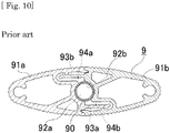
- the heating element cover 9 (described as an "outer shell body” in the specification of Patent Document 1) shown in Fig. 10 has a pair of shell members 91a and 91b having the same shape as each other, and in the shell member 91a, an abutting portion 92a formed with a concave face to be joined so as to be closely fitted to an outer surface of a flow pipe 90 being the heating element, a projecting piece portion 93a, and a recess portion 94a are formed, and in the shell member 91b, an abutting portion 92b formed with a concave face to be joined so as to be closely fitted to the outer surface of the flow pipe 90, a projecting piece portion 93b, and a recess portion 94b are formed.
- the shell members 91a and 91b have a structure in which the respective shell members 91a and 91b are fitted together with each other by inserting the projecting piece portion 94a into the recess portion 95b and inserting the projecting piece portion 94b into the recess portion 95a in a manner of sandwiching the flow pipe 90 with the abutting portions 91a and 91b.
- the heating element cover 9 protects the flow pipe 90 and is a simple structure that can be assembled by only fitting together, no special tool or special technique is required for operation, which enables quick assembly. Also, because the shell members 91a and 91b are identical components, needless expense in component procurement can be eliminated to resultingly achieve a reduction in manufacturing costs.
- Patent Document 1 Japanese Patent No. 5544580
- an inner diameter formed by the abutting portions 92a and 92b is provided slightly larger than an outer diameter of the flow pipe 90, and for the resulting gap, an operation of applying or filling with a heat radiation grease has been performed. This is because, for closely fitting the abutting portions 92a and 92b and the flow pipe 90 in a manner not damaging the flow pipe 90 by a pressing force applied from the abutting portions 92a and 92b, a high processing accuracy becomes necessary for both of the abutting portions 92a and 92b and the flow pipe 90.
- the present invention has been made in view of the above points, and an object thereof is to provide a heating element cover component for protecting a heating element of a radiant cooling and heating apparatus and having an excellent close-fitting property with a heating element disposed inside and excellent in thermal conductivity and a heating element cover, a radiant cooling and heating apparatus, and an air conditioning system using the same heating element cover component.
- a heating element cover component of the present invention includes a hollow outer shell portion of a required length, having required rigidity and thermal conductivity, a substantially half-pipe shaped abutting portion formed with a required thickness at a required site of the outside of the outer shell portion in parallel with a longitudinal direction of the outer shell portion, having flexibility and thermal conductivity, and with a slit penetrating in a thickness direction formed over the entire length in parallel with the longitudinal direction, a connecting portion having flexibility and thermal conductivity, connecting opposed edges of the abutting portion parallel to the longitudinal direction with the outer shell portion, and an engaging portion constituted by engaging elements that are disposed at line-symmetrical positions using a longitudinal straight line located at a widthwise middle of the abutting portion as an axis of symmetry to form a pair structured to be engageable with each other.
- the outer shell portion secures strength to such an extent that the heating element cover component is not easily deformed. Also, the outer shell portion, as a result of having thermal conductivity, can radiate heat transmitted from a covering heating element and absorb heat from the outside (hereinafter, collectively referredto as "exchange heat"). Further, because the outer shell portion is hollow, the member weight is reduced to reduce a load to be applied to the covering heating element.
- the abutting portion as a result of having thermal conductivity, can exchange heat between a covering heating element and the outer shell portion by abutting against the heating element. Also, the abutting portion, as a result of being a substantially half-pipe shaped abutting portion having flexibility and with a slit penetrating in a thickness direction formed over the entire length in parallel with the longitudinal direction, even if the covering heating element has a thickness slightly larger than the abutting portions when sandwiching the heating element therebetween, can warp in a direction in which the slit expands in width to enclose the heating element in a manner not producing a gap between the heating element and the abutting portions.
- the connecting portion having thermal conductivity and connecting the abutting portion and the outer shell portion, heat transfers between the heating element and the outer shell portion via the abutting portion. Further, the connecting portion, as a result of having flexibility, warps following an expanding motion of the abutting portion, and therefore assists the expanding motion of the abutting portion according to the thickness of the heating element.
- the engaging portion as a result of its engaging elements being constructed with the arrangement described above, allows assembling a heating element cover by making mutual joining portions face to face with another heating element cover component having the identical structure and engaging paired engaging elements.
- the slit is formed in a shape that gradually narrows from a side of a hollow region in the outer shell body to a direction of an outer surface of the abutting portion, by constructing the abutting portion to be partially thin only on the periphery of the slit without reducing the thickness thereof in whole, the abutting portion warps with the slit part as a start, and becomes likely to expand in a direction in which the abutting portion swells.
- a heating element cover component when a heating element cover component is manufactured by extruding, if a slit forming part of an extrusion die used is thread-like, it becomes likely that said part chips due to pressurization to pose a problem in durability of the extrusion die, but by providing the slit in the shape described above, a large slit forming part can be secured in the extrusion die, while the slit that is to appear at the outer surface side of the abutting portion can be prevented from becoming wide in width.
- the outer shell portion, the abutting portion, the connecting portion, and the engaging portion are made of aluminum or made of an aluminum alloy, and an alumite processing is applied to an outer surface of the outer shell portion, the abutting portion, the connecting portion, and the engaging portion and an inner surface of the outer shell portion, corrosion resistance is improved by a formed film.
- a film formed on the inner surface of the outer shell portion can improve resistance to corrosion caused by a temperature change or dew condensation that occurs in the hollow region in the outer shell portion.
- a film formed on the outer surface of the outer shell portion etc. can improve heat dissipation to increase the efficiency of heat exchange.
- an alumite film formed on the abutting portion does not conduct electricity because of having insulating properties and thereby prevents the occurrence of electrolytic corrosion (galvanic corrosion) that possibly occurs when the heating element being an attaching target is a dissimilar metal such as copper.
- one of the engaging elements is a projecting piece that projects in a direction opposite to the outer shell portion and is formed with a latching pawl
- the other of the engaging elements is a projecting piece inserting portion that is set to a size capable of receiving the projecting piece and is capable of latching the latching pawl
- only making respective joining portions of a pair of heating element cover components face to face to be fitted together by inserting the projection piece of one heating element cover component into the projecting piece inserting portion of the other heating element cover component to latch the latching pawl and likewise inserting the projection piece of the other heating element cover component into the projecting piece inserting portion of the one heating element cover component to latch the latching pawl allows strongly fixedly fixing the respective heating element cover components.
- the engaging elements have a simple structure of only fitting the pro jectingpiece and the projecting piece inserting portion together, no special tool or special technique is required for an assembling operation to a covering heating element, which thus enables quick assembly.
- a heating element cover of the present invention has a structure of a pair of heating element cover components each including a hollow outer shell portion of a required length, having required rigidity and thermal conductivity, a substantially half-pipe shaped abutting portion formed with a required thickness at a required site of the outside of the outer shell portion in parallel with a longitudinal direction of the outer shell portion, having flexibility and thermal conductivity, and with a slit penetrating in a thickness direction formed over the entire length in parallel with the longitudinal direction, a connecting portion having flexibility and thermal conductivity, connecting opposed edges of the abutting portion parallel to the longitudinal direction with the outer shell portion, and an engaging portion constituted by engaging elements that are disposed at line-symmetrical positions using a longitudinal straight line located at a widthwise middle of the abutting portion as an axis of symmetry to form a pair structured to be engageable with each other, of which the engaging elements mutually paired are engaged with each other in a manner joining the abutting portions together with the engaging
- the outer shell portion secures strength to such an extent so as not to easily deform. Moreover, the outer shell portion prevents a covering heating element from being deformed or damaged by an outside pressure or impact. Also, the outer shell portion, as a result of having thermal conductivity, can exchange heat with the covering heating element. The surface area can thereby be made wider than when the heating element is directly exposed for use, and heat dissipation and heat absorption are improved to have an excellent heat exchange efficiency. Further, because the outer shell portion is hollow, the member weight is reduced to reduce a load to be applied to the covering heating element.
- the abutting portion as a result of having thermal conductivity, can exchange heat between a covering heating element and the outer shell portion by abutting against the heating element. Also, the abutting portion, as a result of being a substantially half-pipe shaped abutting portion having flexibility and with a slit penetrating in a thickness direction formed over the entire length in parallel with the longitudinal direction, even if the covering heating element has a thickness slightly larger than the abutting portions when sandwiching the heating element therebetween, can warp in a direction in which the slit expands in width to enclose the heating element in a manner not producing a gap between the heating element and the abutting portions.
- the connecting portion having thermal conductivity and connecting the abutting portion and the outer shell portion, heat transfers between the heating element and the outer shell portion via the abutting portion. Further, the connecting portion, as a result of having flexibility, warps following an expanding motion of the abutting portion, and assists the expanding motion of the abutting portion according to the thickness of the heating element.
- the engaging portion as a result of its engaging elements being constructed with the arrangement described above, allows assembling a heating element cover by making mutual joining portions face to face with another heating element cover component having the identical structure and engaging paired engaging elements.
- a heating element cover can be obtained.
- the respective heating element cover components are joined, because the opposed ends of the respective abutting portions are also joined as a result of the respective engaging elements being present at the line-symmetrical positions described above, into the heating element cover thus obtained, the heating element can be appropriately fitted.
- the heating element cover is improved in thermal conductivity and heat exchange efficiency.
- the joined abutting portions are, even with their diameter being slightly smaller than that of the heating element, constructed so that the respective abutting portions can be deformed by warping to be closely fitted, and can therefore be attached, because of the construction described above, even with some errors, although a high processing accuracy has conventionally been required for closely fitting the abutting portions and the heating element.
- this heating element cover has a pair of constituting heating element cover components being identical components, needless expense in component procurement can be eliminated to resultingly achieve a reduction in manufacturing costs.
- a radiant cooling and heating apparatus includes a support frame, a heating element which is disposed in an in-between region sandwiched by the support frame or surrounded by the support frame, inside of which a flowable heating medium can flow through, and which consists of a plurality of tubular parts laid thereacross at an interval, and a heating element cover having a structure of a pair of heating element cover components installed for each of the tubular parts of the heating element, and each including a hollow outer shell portion of a required length, having required rigidity and thermal conductivity, a substantially half-pipe shaped abutting portion formed with a required thickness at a required site of the outside of the outer shell portion in parallel with a longitudinal direction of the outer shell portion, having flexibility and thermal conductivity, and with a slit penetrating in a thickness direction formed over the entire length in parallel with the longitudinal direction, a connecting portion having flexibility and thermal conductivity, connecting opposed edges of the abutting portion parallel to the longitudinal direction with the outer shell
- the support frame supports the heating element and the heating element cover at a required interval. Also, the heating element, as a result of a flowable heating medium flowing through the inside thereof, transmits heat to the heating element cover that is in contact with its tubular parts.
- the outer shell portion of the heating element cover secures strength to such an extent so as not to easily deform, and prevents the heating element from being deformed or damaged by an outside pressure or impact.
- the outer shell portion as a result of having thermal conductivity, can exchange heat by, for example, radiating heat transmitted from the heating element to the surroundings. The surface area can thereby be made wider than when the heating element is directly exposed for use, and heat dissipation and heat absorption are improved to have an excellent heat exchange efficiency.
- the outer shell portion is hollow, the member weight is reduced to reduce a load to be applied to the heating element and the support frame.
- the abutting portion of the heating element cover can exchange heat between an abutted heating element and the outer shell portion.
- the abutting portion as a result of being a substantially half-pipe shaped abutting portion having flexibility and with a slit penetrating in a thickness direction formed over the entire length in parallel with the longitudinal direction, even if the tubular part of the heating element has a thickness slightly larger than the abutting portions when sandwiching the heating element therebetween, can warp in a direction in which the slit expands in width to enclose the heating element in a manner not producing a gap between the heating element and the abutting portions.
- the connecting port ion of the heating element cover having thermal conductivity and connecting the abutting portion and the outer shell portion, heat transfers between the heating element and the outer shell portion via the abutting portion.
- the connecting portion as a result of having flexibility, warps following an expanding mot ion of the abutting portion, and assists the expanding motion of the abutting port ion according to the thickness of the heating element.
- the engaging portion of the heating element cover allows assembling a heating element cover by making mutual joining portions face to face with another heating element cover component having the identical structure and engaging paired engaging elements.
- the radiant cooling and heating apparatus allows assembling a heating element cover by engaging the engaging elements mutually paired, of the respective heating element cover components described above, with each other in a manner joining the abutting portions together with the engaging elements made face to face with each other.
- the respective heating element cover components are joined, because the opposed ends of the respective abutting portions are also joined as a result of the respective engaging elements being present at the line-symmetrical positions described above, into the heating element cover thus obtained, the heating element can be appropriately fitted.
- the heating element cover is improved in thermal conductivity and heat exchange efficiency.
- the joined abutting portions are, even with their diameter being slightly smaller than that of the heating element, constructed so that the respective abutting portions can be deformed by warping to be closely fitted, and can therefore be attached, because of the construction described above, even with some errors, although a high processing accuracy has conventionally been required for closely fitting the abutting portions and the heating element.
- this heating element cover has a pair of constituting heating element cover components being identical components, needless expense in component procurement can be eliminated to resultingly achieve a reduction in manufacturing costs.
- an air conditioning system of the present invention includes a radiant cooling and heating apparatus including a support frame, a heating element which is disposed in an in-between region sandwiched by the support frame or surrounded by the support frame, inside of which a flowable heating medium can flow through, and which consists of a plurality of tubular parts laid thereacross at an interval, a heating element cover having a structure of a pair of heating element cover components installed for each of the tubular parts of the heating element, and each including a hollow outer shell portion of a required length, having required rigidity and thermal conductivity, a substantially half-pipe shaped abutting portion formed with a required thickness at a required site of the outside of the outer shell portion in parallel with a longitudinal direction of the outer shell portion, having flexibility and thermal conductivity, and with a slit penetrating in a thickness direction formed over the entire length in parallel with the longitudinal direction, a connecting portion having flexibility and thermal conductivity, connecting opposed edges of the abutting portion parallel to the longitudinal direction with
- the support frame of the radiant cooling and heating apparatus supports the heating element and the heating element cover at a required interval.
- the heating element of the radiant cooling and heating apparatus as a result of a refrigerant supplied from the air conditioner flowing through the inside thereof, transmits heat to the heating element cover that is in contact with its tubular parts.
- the outer shell portion of the heating element cover secures strength to such an extent so as not to easily deform, and prevents the heating element from being deformed or damaged by an outside pressure or impact.
- the outer shell portion as a result of having thermal conductivity, can exchange heat by, for example, radiating heat transmitted from the heating element to the surroundings. The surface area can thereby be made wider than when the heating element is directly exposed for use, and heat dissipation and heat absorption are improved to have an excellent heat exchange efficiency.
- the outer shell portion is hollow, the member weight is reduced to reduce a load to be applied to the heating element and the support frame.
- the abutting portion of the heating element cover can exchange heat between an abutted heating element and the outer shell portion.
- the abutting portion as a result of being a substantially half-pipe shaped abutting portion having flexibility and with a slit penetrating in a thickness direction formed over the entire length in parallel with the longitudinal direction, even if the tubular part of the heating element has a thickness slightly larger than the abutting portions when sandwiching the heating element therebetween, can warp in a direction in which the slit expands in width to enclose the heating element in a manner not producing a gap between the heating element and the abutting portions.
- the connecting port ion of the heating element cover having thermal conductivity and connecting the abutting portion and the outer shell portion, heat transfers between the heating element and the outer shell portion via the abutting portion.
- the connecting portion as a result of having flexibility, warps following an expanding mot ion of the abutting portion, and assists the expanding mot ion of the abuttingportion according to the thickness of the heating element.
- the engaging portion of the heating element cover allows assembling a heating element cover by making mutual joining portions face to face with another heating element cover component having the identical structure and engaging paired engaging elements.
- the air conditioner as a result of being one including a refrigerant circuit in which a compressor, an expansion valve, a flow path switching valve, an indoor side heat exchanger, and an outdoor side heat exchanger are connected by piping to circulate a refrigerant to perform a refrigeration cycle and supplying air that has undergone heat exchange with the refrigerant by the indoor side heat exchanger to an indoor space by a fan, can perform air conditioning of the interior of the installation space by forced convection due to blown air.
- the radiant cooling and heating apparatus allows assembling a heating element cover by engaging the engaging elements mutually paired, of the respective heating element cover components described above, with each other in a manner joining the abutting portions together with the engaging elements made face to face with each other.
- the respective heating element cover components are joined, because the opposed ends of the respective abutting portions are also joined as a result of the respective engaging elements being present at the line-symmetrical positions described above, into the heating element cover thus obtained, the heating element can be appropriately fitted.
- the heating element cover is improved in thermal conductivity and heat exchange efficiency.
- the joined abutting portions are, even with their diameter being slightly smaller than that of the heating element, constructed so that the respective abutting portions can be deformed by warping to be closely fitted, and can therefore be attached, because of the construction described above, even with some errors, although a high processing accuracy has conventionally been required for closely fitting the abutting portions and the heating element.
- this heating element cover has a pair of constituting heating element cover components being identical components, needless expense in component procurement can be eliminated to resultingly achieve a reduction in manufacturing costs.
- the radiant cooling and heating apparatus as a result of being incorporated in the refrigerant circuit of the air conditioner, is supplied with a refrigerant from the air conditioner side, equipment such as a compressor becomes no longer necessary for the radiant cooling and heating apparatus, and it also becomes possible to perform control coupled with the air conditioner.
- the radiant cooling and heating apparatus during operation, a person in the surrounding area never feels an uncomfortable draft sensation, and air heated or cooled by the heating element cover directly warms or cools a space in front thereof, and can efficiently warm and cool the installation space because convection occurs in the interior of the installation space.
- the air conditioning system described above by operating the radiant cooling and heating apparatus and the air conditioner in combination, enables approaching a target temperature in a short time by mainly operating the air conditioner at start-up, and thereafter by mainly operating the air conditioning device, enables maintaining the temperature of the interior of the installation space, and the fan operating time of the indoor heat exchanger can be held short to perform air conditioning that does not provide an uncomfortable draft sensation to the human body.
- radiant heat from the radiant cooling and heating apparatus acts directly on the body sensation of a person that is present in the vicinity, while the air conditioner performs air conditioning of the entirety, and therefore, the time until comfort is provided for the person in the surrounding area can be shortened than when either the air conditioner or the radiant cooling and heating apparatus is operated alone. Further, convecting the radiant heat from the radiant cooling and heating apparatus and blown air from the fan allows quickly making the temperature of the interior of the installation space uniform.
- the heating element cover component according to the present invention can provide one for protecting a heating element of a radiant cooling and heating apparatus and having an excellent close-fitting property with a heating element disposed inside and excellent in thermal conductivity.
- the heating element cover according to the present invention can provide one for protecting a heating element of a radiant cooling and heating apparatus and having an excellent close-fitting property with a heating element disposed inside and excellent in thermal conductivity.
- the radiant cooling and heating apparatus can provide one for protecting its heating element and having an excellent close-fitting property with a heating element disposed inside and excellent in thermal conductivity.
- the air conditioning system according to the present invention can provide one for protecting a heating element of a radiant cooling and heating apparatus incorporated in the air conditioning system and having an excellent close-fitting property with a heating element disposed inside and excellent in thermal conductivity.
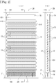
- An air conditioning system A shown in Fig. 1 and Fig. 6 includes a radiant cooling and heating apparatus 1a and an air conditioner 2 including an outdoor machine 21 and a convective indoor machine 22, and the respective portions will be described in the following.
- the radiant cooling and heating apparatus 1a has a support frame 11, a heating element 12, heating element covers 13, a reflector 15, a water receiving portion 16, and a panel body 17.
- the support frame 11 has support portions 110 provided to stand on an installation surface F (if indoors, a floor surface or the like) of the radiant cooling and heating apparatus 1a and disposed at an interval in the horizontal direction.
- the respective support portions 110 store inside connecting parts located at both ends of the heating element 12 to be described later in a manner not visible from the outside (refer to Fig. 2(a) ).
- the heating element 12 is a copper-made tubular body through the inside of which a refrigerant can flow, and is disposed in a region between the support portions 110 of the support frame 11.
- the heating element 12 has a structure, in a manner connecting at both end sides, meandering in an up-and-down direction so as to run as a whole along an identical vertical plane, in which heating element covers 13 are respectively mounted on respective horizontal parts arranged at regular intervals.
- Connecting portions 181 and 182 are provided over and under the radiant cooling and heating apparatus 1a, respectively, and these are connecting parts to an inlet pipe or return pipe of a refrigerant that flows to or from the heating element 12.
- Each horizontal part of the heating element 12 is formed with an outer diameter of its cross-section that is substantially the same as or slightly larger than an inner diameter of a region being circular in cross-section constituted by an abutting portion 134a and an abutting portion 134b when heating element cover components 130a and 130b are fitted to each other.
- the outer diameter of each horizontal part of the heating element 12 has a numerical value of 105 when the numerical value of the inner diameter of a circular region constituted by the abutting port ion 134a and the abutting port ion 134b is provided as 100.
- the heating element cover 13 covers the heating element 12, and has a structure capable of dissipating to the outside heat transmitted from the heating element 12.
- the heating element cover 13 having a required length is constituted by a combination of a pair of heating element cover components 130a and 130b having the same shape as each other.
- the heating element cover components 130a and 130b when fitted together have an outer shape of a cross-section being a slightly flat substantially elliptical shape (refer to Fig. 5(b) ).
- the respective heating element covers 13 are attached to the support frame 11 in a manner such that long axis directions of their cross-sections are similarly downwardly inclined toward the reflector 15 (refer to Fig. 2(b) ).
- An inclination angle when attaching the respective heating element covers 13 to the support frame 11 is 45° where the angle at which the long axis of an elliptical sectional shape of the heating element cover 13 becomes horizontal is provided as 0°.
- the heating element cover components 130a and 130b are made of an aluminum alloy having required rigidity and thermal conductivity, and are manufactured by extrusion molding and cut at a required length to be used.
- the heating element cover components 130a and 130b are the same in structure as each other, and therefore, the heating element cover components 130a will be described by way of example in the following.
- the heating element cover component 130a has an outer shape of a cross-section being a slightly flat substantially semielliptical shape divided in a short diameter direction as viewed in end elevation, and is made up of an outer shell portion 131a and a joining portion 133a.
- An outer surface of the outer shell portion 131a and the joining portion 133a and an inner surface of the outer shell portion 131a are applied with an alumite processing.
- the outer shell portion 131a has a space 132 that continues longitudinally at the inner side. Moreover, the outer shell portion 131a is applied across its entire outer surface and an inner wall of the space 132 excluding the side of a rear surface of the abutting portion 134a with knurling that forms longitudinally extending concavities and convexities.
- the outer shell portion 131a is slightly thick-walled in the vicinity of a projecting piece inserting portion 140a to be described later so as to have flexibility, but other parts are formed with a wall thickness that enables securing required rigidity.
- the joining portion 133a is made up of the abutting portion 134a provided with a slit 135a, connecting portions 136, and an engaging portion having a projecting piece 138a and a projecting piece inserting portion 140a that are engaging elements.
- the abutting portion 134a has a substantially half-pipe shape, and is semicircular as viewed in end elevation.
- the abutting portion 134a is provided at a required site of the outside of the outer shell portion 131a in parallel with the longitudinal direction, and its opposed edges parallel to the longitudinal direction are connected with the outer shell portion 131a by the connecting portions 136 formed with a wall thickness to have flexibility.
- the abutting portion 134a has, at a middle portion in its arc direction, a slit 135a that is provided penetrating in its thickness direction over the entire length in parallel with the longitudinal direction and that connects to the space 132.
- the slit 135a is formed in a shape (substantially wedge shape in cross-section) that gradually narrows from the side of the space 132 being its outer peripheral side to the direction of an inner peripheral side of the abutting portion 134a.
- the slit 135a is formed so as to appear with a width on the order of 0.5 mm to 1 mm at the side of an inner peripheral surface of the abutting portion 134a (side to abut against the heating element 12).
- the projecting piece 138a and the projecting piece inserting portion 140a are disposed at line-symmetrical positions using a longitudinal straight line located at a widthwise middle of the abutting portion 134a as an axis of symmetry (point located at the center of the broken line of Fig. 4 ), and form a pair structured to be engageable with each other.
- the projecting piece 138a projects from one connecting portion 136 to the side opposite to the outer shell portion 131a, and is provided near its front end with a latching pawl 139a.
- the projecting piece inserting portion 140a has an internal space of a size capable of receiving the projecting piece 138a, and is provided, on an inner wall of the internal space, with a latching pawl retaining portion 141a being a projection portion capable of latching the latching pawl.
- the latching pawl retaining portion 141a latches a latching pawl 139b of the heating element cover component 130b being a combination target.
- the outer shell portion 131b corresponds to the outer shell portion 131a to have the same structure, and the joining portion 133b, to the joining portion 133a, and the abutting portion 134b, to the abutting portion 134a, and the slit 135b, to the slit 135a, and the engaging portion 137b, to the engaging portion 137a, and the projecting piece 138b, to the projecting piece 138a, and the latching pawl 139b, to the latching pawl 139a, and the projecting piece inserting portion 140b, to the projecting piece inserting portion 140a, and the latching pawl retaining portion 141b, to the latching pawl retaining portion 141a, respectively.
- the reflector 15 is formed of a heat insulating material, and has a reflecting surface 151 that is not permeable to water, and the reflecting surface 151 is disposed so as to be opposed at an interval to an end edge portion at a lower side in the long axis direction of the heating element cover 13.
- a guide plate 152 bent at an obtuse angle to the side of the heating element cover 13 is attached to a lower end of the reflector 15.
- a front end of the guide plate 152 is structured to be located in the inside of the water receiving portion 16 to be described later.
- the water receiving portion 16 is located below the lowermost one among the heating element covers 13 and under the reflector 151 (more specifically, under a guide plate 142 attached to the reflector 15), and is in a gutter shape opened at an upper part.
- the panel body 17 is formed of a perforated metal, and attached to below the front side of the radiant cooling and heating apparatus 1a.
- the panel body 17 provides a covering for the water receiving portion 16, a piping portion (not shown), etc., so as to serve as a screen when viewed from the front direction. Also, the panel body 17 is attached so that a clearance for ventilation is formed with the installation surface F.
- the outdoor machine 21 and the general convective indoor machine 22 connected therein are connected by refrigerant piping 23.
- the radiant cooling and heating apparatus 1a is communicatively connected in series. Accordingly, the radiant cooling and heating apparatus 1a and the convective indoor machine 22 installed in a room or the like having an air conditioning target space form a part of a refrigerant circuit, and a cooling operation or heating operation can be performed in the air conditioning target space by circulating a refrigerant in the refrigerant circuit.
- the outdoor machine 21 has a publicly known structure having a compressor 211, an outdoor side heat exchanger 212, an expansion valve 213, and a four-way switching valve 214
- the convective indoor machine 22 has a publicly known structure including an indoor side heat exchanger 221 and a blowing fan (not shown).
- This equipment constitutes a so-called blow type air conditioner, and in the following, is sometimes collectively called simply an "air conditioner" when describing actions.
- the indoor side heat exchanger 221 serves as a vaporizer during a cooling operation and as a condenser (radiator) during a heating operation, performs heat exchange between air supplied from the blowing fan or the like and the refrigerant, and generates heating air or cooling air to be supplied to the air conditioning target space.
- the equipment described above is connected via the refrigerant piping 23, and constitutes a part of a refrigeration cycle (refrigerant circuit) of the air conditioning system A.
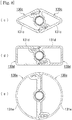
- Fig. 5 is referred to.
- the joining portions 133a and 133b of the heating element cover components 130a and 130b are made face to face, and the projecting piece 138ais located directly opposite the projecting piece inserting portion 140b and the projecting piece 138b is located directly opposite the projecting piece inserting portion 140a, and the heating element 12 is disposed in a manner sandwiching between the abutting portions 134a and 134b.
- the slits 135a and 135b have not yet been expanded.
- the heating element cover components 130a and 130b are fitted to each other.
- the outer shape of a cross-section of the horizontal part of the heating element 12 has a diameter slightly larger than the inner diameter of the circular region constituted by the abutting portions 134a and 134b, a force to be applied in the direction of P1 is generated when the heating element 12 is fitted in the abutting portion 134a (134b) (although a partially enlarged view of the abutting portion 134b is omitted, the same action as in the partially enlarged view of the abutting portion 134a occurs).
- the abutting portion 134a (134b) warps due to the force applied in the direction of P1 and expands in the direction of P2 and P3, and a force is also applied in the direction of P4 to P7 to warp the connecting portions 136 and the outer shell portion 131a (131b) in part, as well.
- the heating element cover components 130a and 130b can thereby be attached to the horizontal part of the heating element 12, and after the attachment, the heating element 12 and the heating element cover components 130a and 130b are closely fitted and kept so as to be immovable.
- the heating element cover components 130a and 130b are joined, because the opposed ends of the arc forms (semicircular forms) of the abutting portions 134a and 134b are also joined as a result of the projecting piece 138a and the projecting piece inserting portion 140b and the projecting piece 138b and the projecting piece inserting portion 140a, which are respectively engaging elements, being present at the aforementioned line-symmetrical positions, the heating element cover 13 thus attached can be appropriately fitted over the circular pipe-shaped heating element 12.
- the abutting portions 134a and 134b are constructed to be partially thin only on the periphery of the slit without reducing the thickness thereof in whole, and the abutting portions 135a and 135b warp with the slit part as a start to become likely to expand in a direction in which each abutting portion swells.
- the thermal conductivity and heat exchange efficiency are improved.
- the abutting portions 134a and 134b are, even with their diameter being slightly smaller than that of the heating element 12, constructed so that the respective abutting portions can be deformed by warping to be closely fitted, and can therefore be attached, because of the construction described above, even with some errors, although a high processing accuracy has conventionally been required for closely fitting the abutting portions and the heating element.
- An alumite film formed on the abutting portions 134a and 134b does not conduct electricity because of having insulating properties, and prevents the occurrence of electrolytic corrosion (galvanic corrosion) caused by a difference in material between the abutting portions and the heating element.
- electrolytic corrosion galvanic corrosion
- electrolytic corrosion does not occur or is unlikely to occur, for example, when the heating element is made of the same aluminum alloy, it is also optionally possible not to perform an alumite processing or the like.
- heating element cover components 130a (130b) being constituting components are identical, needless expense in component procurement can be eliminated to resultingly achieve a reduction in manufacturing costs.
- the heating element cover 13 has the structure described above and is simply formed by only fitting the heating element cover components 130a (130b) together, no special tool or special technique is required for an assembling operation to the heating element 12, which thus enables quick assembly.
- the heating element cover 13 thus radiates radiant heat to the outside.
- a portion generated from a side disposed on the front side of the radiant cooling and heating apparatus 1a is directly radiated to the front direction side of the radiant cooling and heating apparatus 1a, and a portion generated from a side disposed on the back side is reflected by the reflecting surface 151 of the reflector 23, and radiated to the front direction side of the radiant cooling and heating apparatus 1a through clearance gaps between the respective heating element covers 13.
- the attaching angle of the heating element cover 13 is 45°, a radiation flux generated from the side to be a front side of the heating element cover 13 is likely to head for the front side of the radiant cooling and heating apparatus 1a and a front-side floor surface, and can directly provide either cool or warm radiant heat to a person present on the front side of the radiant cooling and heating apparatus 1a.
- the heating element cover 13 prevents the heating element 12 from being deformed or damaged by an outside pressure or impact. Moreover, the heating element cover 13 makes the surface area where radiant heat is generated wider than when the heating element 12 dissipates heat alone, and also improves the heat exchange efficiency. Further, also when heat is absorbed, the surface area is made wider than when the heating element 12 absorbs heat alone, and the heat exchange efficiency is therefore improved. In addition, the thermal conduction pathway when absorbing heat is opposite (heading for the heating element from the outer shell portions) to that of the heat dissipation described above.
- the dew condensation water T flows down only to the side of the reflector 23. Then, the dew condensation water (not shown) adhered to the reflecting surface 151 runs down the plate surface to flow down onto the water receiving portion 16 located below. Further, the dew condensation water does not splatter onto the front side of the radiant cooling and heating apparatus 1a even if dripping onto the heating element cover 13 located at a lower height because the heating element cover 13 is inclined to the side of the reflector 23 as described above.
- the water receiving portion 16 changes the direction of convection to guide cold air so as to flow to the front side of the radiant cooling and heating apparatus 1a to thereby prevent dew condensation from being produced on the installation surface F as a result of cold air that is convecting from an up to down direction during cooling directly contacting the installation surface F.
- the radiant cooling and heating apparatus 1a With the radiant cooling and heating apparatus 1a, during operation, because the flow of air that is generated in the space of an installation region is thus by natural convection due to a difference in temperature of the interior of the space not by blown air due to forced convection as in a conventional air conditioner, a person in the surrounding area never feels an uncomfortable draft sensation, and air heated or cooled by the heating element cover 13 directly warms or cools a space in front of the radiant cooling and heating apparatus 1a, and can efficiently warm and cool the installation space because convection occurs in the installation space. Also, the radiant cooling and heating apparatus 1a can prevent staining the periphery of an installation site with produced dew condensation water.
- the air conditioning system A makes use of the advantages of each of the radiant cooling and heating apparatus and air conditioner (the air conditioner being able to make the interior of the space quickly reach a target temperature by forced convection, the radiant cooling and heating apparatus not providing a draft sensation to the user) to complement their respective disadvantages (the air conditioner providing a draft sensation to the user, the radiant cooling and heating apparatus taking a long time to make the interior of the space reach a target temperature).
- the air conditioning system A when switching cooling and heating, the air conditioning system A performs operation by reversing the refrigerant flowing direction.
- the air conditioning system A for example, by mainly operating the air conditioner 2 at first, enables approaching a target temperature in a short time, and thereafter by mainly operating the radiant cooling and heating apparatus 1a, enables maintaining the temperature of the interior of the space.
- the fan operating time of the convective indoor machine 22 can thereby be held short to enable air conditioning that does not provide an uncomfortable draft sensation to the human body.
- radiant heat from the radiant cooling and heating apparatus 1a acts directly on the body sensation of a person that is present in the nearby surrounding area, while the air conditioner 2 performs air conditioning of the entirety, and therefore, the time until comfort is provided for the person in the surrounding area can become shorter than when either the air conditioner 2 or the radiant cooling and heating apparatus 1a is operated alone. Further, convecting the radiant heat from the radiant cooling and heating apparatus 1a and blown air from the air conditioner 2 allows realizing a uniform temperature of the interior of the space in a short time.
- the heating element cover component 130f shown in Fig. 7 (a) is a modification in the slit of the heating element cover component.
- a slit 135f of the heating element cover component 130f is formed in a shape that is straight with a constant width from the side of the space 132 to the direction of an inner peripheral side of an abutting portion 134f.
- the slit width is narrower because the contact area with the heating element 12 is reduced if the slit width is wider.
- the slit has a narrow width, because a large load is applied to a slit forming part of an extrusion molding die and said part is narrow and weak in strength, the die may be damaged.
- molding may first be performed with a slightly wide slit width as in the heating cover component 130f, and by pressuring the heating cover component 130f in a manner flattening in the short diameter direction, the slit 135f may be narrowed in width.
- the slit 135f after being narrowed in width can expand to a moderate width according to the size of the heating element 12, which can prevent the contact area with the heating element 12 from being excessively reduced by excessive widening of the slit width.
- the heating element cover component 130g shown in Fig. 7 (b) is a modification in the engaging elements of the engaging portion.
- the engaging elements of the engaging portion 137g are constituted of a guide piece 191 projecting in a hook shape and a guide groove 192 in a shape that allows storing the guide piece 191 by sliding from its end face direction.
- the guide piece 191 and the guide groove 192 are disposed at line-symmetrical positions using a longitudinal straight line located at a widthwise middle of an abutting portion 134g as an axis of symmetry, and form a pair structured to be engageable with each other.
- the heating element cover component 130g is substantially the same in construction and action of other parts as the heating element cover component 130a (130b) in the foregoing, and description thereof will therefore be omitted.
- Fig. 8 is referred to.
- Fig. 8(c) shows modification 3
- Fig. 8(d) shows modification 4
- Fig. 8(e) shows modification 5, and these are modifications in the outer shell portions of the hating element cover component.
- the hating element cover component 130c shown in modification 3 of Fig. 8(c) has an outer shape of a cross-section being a substantially triangular shape.
- the hating element cover component 130d shown in modification 4 of Fig. 8(d) has an outer shape of a cross-section being a substantially quadrilateral shape.
- the hating element cover component 130e shown in modification 5 of Fig. 8(e) has an outer shape of a cross-section being a substantially semicircular shape.
- the heating element cover components 130c, 130d, and 130e are substantially the same in construction and action of other parts as the heating element cover component 130a (130b) in the foregoing, and description thereof will therefore be omitted.
- the radiant cooling and heating apparatus 1b shown in Fig. 9 is a modification where the direction in which the heating element and heating element covers are disposed is the vertical direction. As shown in Fig. 9(b) , the respective heating element covers 13b enclosing the heating element 12b are disposed in inverted-V shape (or zigzag) configurations such that with mutually adjacent heating element covers 13b, the outer surfaces are not opposed to each other and mutual influence by radiant heat is thereby avoided, and the heat exchange efficiency can be improved in regard to this point as well. In addition, the radiant cooling and heating apparatus 1b is substantially the same in construction and action of other parts as those of the radiant cooling and heating apparatus 1a in the foregoing, and description thereof will therefore be omitted.
- the radiant cooling and heating apparatus 1a includes the reflector 15, but is not limited thereto, and for example, the reflector 15 may be eliminated to make the radiant cooling and heating apparatus 1a emit radiant heat to both the front side and back side.
- the engaging elements of the engaging portion consist of the projecting piece having a latching pawl and a projecting piece inserting portion having a latching pawl retaining portion, but other publicly known engaging structures may be adopted. Also, the engaging elements may be provided into a separable mechanism, and in that case, the heating element cover can be disassembled to improve maintenance properties of cleaning and parts replacement.
- the air conditioning system A is constituted by one outdoor machine 21, one convective indoor machine 22, and one radiant cooling and heating apparatus 1a, but the number of each of the machines/apparatuses is not limited to the number shown in the figures.
- the slit 135a is formed in a shape (substantially wedge shape in cross-section) that gradually narrows from the side of the space 132 being its outer peripheral side to the direction of an inner peripheral side of the abutting portion 134a, but is not limited thereto, and for example, it may be straight as in modification 1 described above.
- the slit may also be formed by post-processing such as cutting after forming a heating element cover component without a slit (which is the same as the heating element cover component 130a in parts other than the slit).
- the heating element cover component 130a, 130b has an outer diameter of a cross-section being a slightly flat substantially semielliptical shape, but is not limited thereto, and for example, it may be appropriately set into various shapes as in modification 3, modification 4, and modification 5 described above.
- the direction in which the heating element 12 and the heating element covers 13 are disposed is the horizontal direction, but is not limited thereto, and for example, it may be the vertical direction as in modification 6 described above, and can be appropriately changed to various directions.
- the heating element 12 is a meandering pipe as described above, but is not limited thereto, and for example, it may be a ladder-shaped heating element having a pair of tubular bodies extending in the up-and-down direction and a plurality of tubular heat generating portions laid so as to flow liquid between the tubular bodies.
- the connecting portion 181 and the connecting portion 182 of the heating element 12 are provided in the positions described above, but are not limited thereto, and the positions and numbers thereof can be appropriately set.
- the inclination angle when attaching the heating element cover 13 to the support frame 11 is 45°, but is not limited thereto, and for example, it suffices to be in a range of 1° to 89°.
- the inclination angle of the heating element cover 13 described above is preferably in a range of 35° to 70°, because, if in the same inclination angle range, as to be described later, a radiation flux generated from the side to be a lower surface side of the heating element cover 13 is likely to head for a front-side floor surface from the front side of the air conditioning device 1a.
- the heating element cover component 130a, 130b is applied at its inner and outer surfaces with knurling and an alumite processing, but is not limited thereto, and for example, one type or a combination of aplurality of types of processing or coating selected from among other types of coating including heat dissipation coating, far infrared ray emission coating, and coating having a deodorizing function, an antibacterial function, or a volatile organic compound adsorption-decomposition function can be applied to provide various functions for the heating element cover. Also, such processing does not eliminate being applied only to either of the inner and outer surfaces described above.
- the heating element cover is improved in heat dissipation, and if a far infrared ray emission coating is applied to the heating element cover, the far infrared rays emitted therefrom, together with the radiant heat, cause indoor temperature adjustment to be performed efficiently.
- a coating having a deodorizing function, an antibacterial function, or a volatile organic compound adsorption-decomposition function to the heating element cover, the maintenance of the air conditioning device is made simpler and comfortable use can be realized by these functions.
- a processing such as a water-repelling processing or a guide groove with which dew condensation water is likely to flow down is applied, and a processing to enhance a heat dissipation effect such as knurling is applied to a region facing the side to be the front of the radiant cooling and heating apparatus 1a.
- dew condensation water produced on that heating element cover 13 or dew condensation water that has dripped from the heating element cover 13 located at an upper height is likely to flow down to the side of the reflector 15, and is unlikely to head for the side to be the front of the radiant cooling and heating apparatus 1a.
- a measure against dew condensation water by applying a hydrophilization processing such as blasting to a surface of the region facing the side of the reflector 15 is also not excluded.
- knurling etc. is applied to the side, of the outer surface of the heating element cover 13, to be the front of the radiant cooling and heating apparatus 1a, the efficiency of heat dissipation to a person or space located on the front side is excellent.
- the abutting portion 134a, 134b is semicircular as viewed in end elevation, but is not limited thereto, and for example, if the heating element is a triangular or quadrilateral angular pipe, it may be such an angular shape so as to be able to sandwich the same.
- the panel body 17 is attached to below the front side of the front of the radiant cooling and heating apparatus 1a, but is not limited thereto, and there may be a form in which the panel body is attached to above the front side of the radiant cooling and heating apparatus 1a when a piping portion (not shown) or the like is provided in an upper portion.
- a refrigerant is used as a flowable heating medium, but the flowable heating medium is not limited thereto, and examples thereof include warm (hot) water, steam, coldwater, liquid phase refrigerants, gas-liquid two phase refrigerants, and gas phase refrigerants of hydrochlorofluorocarbon, hydrofluorocarbon, etc., but the flowable heating medium is not limited thereto, and other publicly known flowable heating media may be adopted.
- the flowable heating medium is warm water or cold water, handling is easier than when it is oil or a chemical, and there is less environmental burden at disposal.
- the radiant cooling and heating apparatus 1a uses, as the flowable heating medium, a refrigerant that is in common with the refrigerant circuit of the air conditioner 2, but the radiant cooling and heating apparatus 1a and the air conditioner 2 may respectively use exclusive refrigerants, and the radiant cooling and heating apparatus 1a and the air conditioner 2 may respectively use different flowable heating media.
- the numerical value of the outer diameter of each horizontal part of the heating element 12 is provided so as to become 105 when the numerical value of the inner diameter of a circular region constituted by the abutting portion 134a and the abutting portion 134b is provided as 100, but it is not limited thereto, and for example, the numerical value of the outer diameter of each horizontal part of the heating element 12 is preferably in a range of 100 to 112.
- the heating element cover 13 by using a heat transfer member such as a heat radiation grease as is conventionally done even when the numerical value of the outer diameter of each horizontal part of the heating element 12 is 99 or less when the numerical value of the inner diameter of a circular region constituted by the abutting portion 134a and the abutting portion 134b is provided as 100, but for the reason described above, it is preferable that the inner diameter of a circular region constituted by the respective abutting portions is the same as or slightly larger than the outer diameter of each horizontal part of the heating element.
- a heat transfer member such as a heat radiation grease
- the connecting portions 136 when the abutting portion 135a etc., expands in the direction in which the same swells, the connecting portions 136 (particularly, the connecting portion 136 on the side where the projecting piece inserting portion 140a is formed) is also deformed by warping (refer to P4 to P7 in Fig. 5(b) for the direction of deformation), and the warping deformation occurs, for example, about where the outer shell portion 131a etc. , and the connecting portion 136 connect and/or about a middle (refer to Fig. 4 ) of the outer periphery of the outer shell portion 131a etc., in some cases.
Landscapes
- Engineering & Computer Science (AREA)
- Mechanical Engineering (AREA)
- Physics & Mathematics (AREA)
- General Engineering & Computer Science (AREA)
- Life Sciences & Earth Sciences (AREA)
- Thermal Sciences (AREA)
- Geometry (AREA)
- Sustainable Development (AREA)
- Chemical & Material Sciences (AREA)
- Combustion & Propulsion (AREA)
- Devices For Blowing Cold Air, Devices For Blowing Warm Air, And Means For Preventing Water Condensation In Air Conditioning Units (AREA)
- Resistance Heating (AREA)
- Air-Conditioning For Vehicles (AREA)
Applications Claiming Priority (1)
| Application Number | Priority Date | Filing Date | Title |
|---|---|---|---|
| PCT/JP2016/056366 WO2017149692A1 (ja) | 2016-03-02 | 2016-03-02 | 発熱体カバー部品、発熱体カバー、輻射式冷暖房機、および空気調和システム |
Publications (3)
| Publication Number | Publication Date |
|---|---|
| EP3232128A4 EP3232128A4 (de) | 2017-10-18 |
| EP3232128A1 true EP3232128A1 (de) | 2017-10-18 |
| EP3232128B1 EP3232128B1 (de) | 2019-01-02 |
Family
ID=57939765
Family Applications (1)
| Application Number | Title | Priority Date | Filing Date |
|---|---|---|---|
| EP16708921.8A Active EP3232128B1 (de) | 2016-03-02 | 2016-03-02 | Heizelementabdeckungskomponente, heizelementabdeckung, strahlungskühlungs- und -erwärmungsvorrichtung und klimatisierungssystem |
Country Status (10)
| Country | Link |
|---|---|
| US (1) | US10066844B2 (de) |
| EP (1) | EP3232128B1 (de) |
| CN (1) | CN107407486B (de) |
| CA (1) | CA2924556C (de) |
| HK (1) | HK1244311B (de) |
| MY (1) | MY188054A (de) |
| PH (1) | PH12016500539A1 (de) |
| SG (1) | SG11201602334PA (de) |
| TW (1) | TWI622740B (de) |
| WO (1) | WO2017149692A1 (de) |
Families Citing this family (9)
| Publication number | Priority date | Publication date | Assignee | Title |
|---|---|---|---|---|
| JP6848893B2 (ja) * | 2018-01-29 | 2021-03-24 | ダイキン工業株式会社 | 輻射パネル用の固定具および輻射パネルユニット |
| JP6683210B2 (ja) * | 2018-01-29 | 2020-04-15 | ダイキン工業株式会社 | 輻射パネル、及び空気調和装置 |
| JP6960347B2 (ja) * | 2018-02-06 | 2021-11-05 | ダイキン工業株式会社 | 輻射パネル及び空気調和装置 |
| WO2019159721A1 (ja) * | 2018-02-19 | 2019-08-22 | ダイキン工業株式会社 | 空気調和装置 |
| JP7089158B2 (ja) * | 2018-03-16 | 2022-06-22 | ダイキン工業株式会社 | 輻射パネルの製造方法 |
| CN113776181B (zh) * | 2021-09-02 | 2022-09-23 | 珠海格力电器股份有限公司 | 机房加热安装组件和机房 |
| FR3134173B1 (fr) * | 2022-04-04 | 2024-06-14 | Liebherr Aerospace Toulouse Sas | Profilé fendu pour insertion de tube de circulation de fluide et échangeur de chaleur associé |
| KR102769673B1 (ko) * | 2022-04-11 | 2025-02-19 | 권석만 | 전열선이 내장된 히팅파이프 |
| WO2024057503A1 (ja) * | 2022-09-15 | 2024-03-21 | 株式会社エコファクトリー | 伝熱部材、及び輻射パネル |
Family Cites Families (13)
| Publication number | Priority date | Publication date | Assignee | Title |
|---|---|---|---|---|
| DE886919C (de) * | 1951-11-01 | 1955-01-31 | Ferdinand Dipl-Ing Tschinka | Waermeaustauscher |
| US3735465A (en) * | 1969-01-21 | 1973-05-29 | Airco Inc | Assembling apparatus for rolling and clamping a part to a tubular member |
| US4241727A (en) * | 1978-11-06 | 1980-12-30 | Toti Andrew J | Structural assembly, method of forming same, and elongated panel structure resulting therefrom |
| CN2278171Y (zh) * | 1996-05-13 | 1998-04-08 | 乐正伟 | 管壳式换热空调机 |
| JP2002130704A (ja) * | 2000-10-23 | 2002-05-09 | Sanyo Electric Co Ltd | 暖房用放熱器 |
| ITTO20030876A1 (it) | 2003-11-05 | 2005-05-06 | Tubiflex Spa | Canalina per l'ottenimento di guaine atte all'alloggiamento dei condotti degli impianti di condizionamento. |
| US7992623B2 (en) * | 2007-01-10 | 2011-08-09 | Keller Komfort Radiant Systems, Inc. | Radiant heat wall covering system |
| DE102009057904A1 (de) * | 2009-12-11 | 2011-06-16 | Deutsches Zentrum für Luft- und Raumfahrt e.V. | Wärmeübertragungsrohr |
| KR101102526B1 (ko) | 2009-12-30 | 2012-01-03 | 한국수력원자력 주식회사 | 전기 절연용 간격체가 구비된 고온 가열기 |
| US20130063958A1 (en) * | 2011-09-12 | 2013-03-14 | Leader Trend Technology Corp. | Lamp heat dissipating device, and heat dissipating assembly thereof |
| CN202303811U (zh) * | 2011-10-08 | 2012-07-04 | 宁波奥克斯空调有限公司 | 空调挂机外壳 |
| JP5544580B1 (ja) | 2013-07-26 | 2014-07-09 | 株式会社 エコファクトリー | 空気調和装置及び空気調和装置の運転方法 |
| CN204717236U (zh) | 2015-06-03 | 2015-10-21 | 常州北源机械科技发展有限公司 | 管路保温管套 |
-
2016
- 2016-03-02 SG SG11201602334PA patent/SG11201602334PA/en unknown
- 2016-03-02 WO PCT/JP2016/056366 patent/WO2017149692A1/ja not_active Ceased
- 2016-03-02 HK HK18103635.5A patent/HK1244311B/en unknown
- 2016-03-02 CA CA2924556A patent/CA2924556C/en active Active
- 2016-03-02 EP EP16708921.8A patent/EP3232128B1/de active Active
- 2016-03-02 MY MYPI2016700988A patent/MY188054A/en unknown
- 2016-03-02 US US15/022,964 patent/US10066844B2/en active Active
- 2016-03-02 CN CN201680000096.9A patent/CN107407486B/zh active Active
- 2016-03-15 TW TW105107909A patent/TWI622740B/zh active
- 2016-03-21 PH PH12016500539A patent/PH12016500539A1/en unknown
Also Published As
| Publication number | Publication date |
|---|---|
| CA2924556C (en) | 2018-09-25 |
| TW201732204A (zh) | 2017-09-16 |
| CN107407486A (zh) | 2017-11-28 |
| CA2924556A1 (en) | 2017-09-02 |
| EP3232128A4 (de) | 2017-10-18 |
| US20180087787A1 (en) | 2018-03-29 |
| SG11201602334PA (en) | 2017-10-30 |
| MY188054A (en) | 2021-11-15 |
| CN107407486B (zh) | 2019-11-08 |
| HK1244311B (en) | 2019-10-25 |
| TWI622740B (zh) | 2018-05-01 |
| WO2017149692A1 (ja) | 2017-09-08 |
| PH12016500539B1 (en) | 2016-06-13 |
| US10066844B2 (en) | 2018-09-04 |
| EP3232128B1 (de) | 2019-01-02 |
| PH12016500539A1 (en) | 2016-06-13 |
Similar Documents
| Publication | Publication Date | Title |
|---|---|---|
| EP3232128B1 (de) | Heizelementabdeckungskomponente, heizelementabdeckung, strahlungskühlungs- und -erwärmungsvorrichtung und klimatisierungssystem | |
| HK1244311A1 (en) | Heating element cover component, heating elelment cover, radiation cooling and heating equipment, and air-conditioning system | |
| EP3141828B1 (de) | Klimaanlage und klimatisierungssystem | |
| JP2010107151A (ja) | 冷暖房用などのパネル | |
| US11698213B2 (en) | Heat exchanger, indoor unit for air-conditioner, and refrigeration device | |
| JP5355730B2 (ja) | 空調装置 | |
| JP4969998B2 (ja) | 仕切壁構造 | |
| JP6304783B2 (ja) | 空気調和装置 | |
| JP6694199B1 (ja) | 放射パネル | |
| JP5396248B2 (ja) | 個別空間用空調システム | |
| JP3170417U (ja) | 空気調和装置 | |
| JP2009019806A (ja) | 放射パネル | |
| JP7017929B2 (ja) | 空調システム | |
| RU65192U1 (ru) | Кожух напольного отопительного конвектора | |
| HK1237394A1 (en) | Air conditioner and air conditioning system | |
| JP2006098047A (ja) | 管付きパネル | |
| WO2024057503A1 (ja) | 伝熱部材、及び輻射パネル | |
| CN109425247A (zh) | 一种散热器、室外机以及空调器 | |
| JP2018146143A (ja) | 放射パネル | |
| KR20080070299A (ko) | 공기조화시스템 | |
| HK1205237A1 (en) | Air conditioning device |
Legal Events
| Date | Code | Title | Description |
|---|---|---|---|
| STAA | Information on the status of an ep patent application or granted ep patent |
Free format text: STATUS: UNKNOWN |
|
| STAA | Information on the status of an ep patent application or granted ep patent |
Free format text: STATUS: THE INTERNATIONAL PUBLICATION HAS BEEN MADE |
|
| PUAI | Public reference made under article 153(3) epc to a published international application that has entered the european phase |
Free format text: ORIGINAL CODE: 0009012 |
|
| STAA | Information on the status of an ep patent application or granted ep patent |
Free format text: STATUS: REQUEST FOR EXAMINATION WAS MADE |
|
| 17P | Request for examination filed |
Effective date: 20160323 |
|
| A4 | Supplementary search report drawn up and despatched |
Effective date: 20170821 |
|
| AK | Designated contracting states |
Kind code of ref document: A1 Designated state(s): AL AT BE BG CH CY CZ DE DK EE ES FI FR GB GR HR HU IE IS IT LI LT LU LV MC MK MT NL NO PL PT RO RS SE SI SK SM TR |
|
| AX | Request for extension of the european patent |
Extension state: BA ME |
|
| RIN1 | Information on inventor provided before grant (corrected) |
Inventor name: MURAKAMI TAKANOBU |
|
| GRAP | Despatch of communication of intention to grant a patent |
Free format text: ORIGINAL CODE: EPIDOSNIGR1 |
|
| STAA | Information on the status of an ep patent application or granted ep patent |
Free format text: STATUS: GRANT OF PATENT IS INTENDED |
|
| REG | Reference to a national code |
Ref country code: HK Ref legal event code: DE Ref document number: 1244311 Country of ref document: HK |
|
| INTG | Intention to grant announced |
Effective date: 20180709 |
|
| GRAS | Grant fee paid |
Free format text: ORIGINAL CODE: EPIDOSNIGR3 |
|
| GRAA | (expected) grant |
Free format text: ORIGINAL CODE: 0009210 |
|
| STAA | Information on the status of an ep patent application or granted ep patent |
Free format text: STATUS: THE PATENT HAS BEEN GRANTED |
|
| AK | Designated contracting states |
Kind code of ref document: B1 Designated state(s): AL AT BE BG CH CY CZ DE DK EE ES FI FR GB GR HR HU IE IS IT LI LT LU LV MC MK MT NL NO PL PT RO RS SE SI SK SM TR |
|
| DAV | Request for validation of the european patent (deleted) | ||
| DAX | Request for extension of the european patent (deleted) | ||
| REG | Reference to a national code |
Ref country code: GB Ref legal event code: FG4D |
|
| REG | Reference to a national code |
Ref country code: CH Ref legal event code: EP Ref country code: AT Ref legal event code: REF Ref document number: 1084885 Country of ref document: AT Kind code of ref document: T Effective date: 20190115 |
|
| REG | Reference to a national code |
Ref country code: IE Ref legal event code: FG4D |
|
| REG | Reference to a national code |
Ref country code: DE Ref legal event code: R096 Ref document number: 602016008987 Country of ref document: DE |
|
| REG | Reference to a national code |
Ref country code: NL Ref legal event code: FP |
|
| REG | Reference to a national code |
Ref country code: LT Ref legal event code: MG4D |
|
| REG | Reference to a national code |
Ref country code: AT Ref legal event code: MK05 Ref document number: 1084885 Country of ref document: AT Kind code of ref document: T Effective date: 20190102 |
|
| PG25 | Lapsed in a contracting state [announced via postgrant information from national office to epo] |
Ref country code: PT Free format text: LAPSE BECAUSE OF FAILURE TO SUBMIT A TRANSLATION OF THE DESCRIPTION OR TO PAY THE FEE WITHIN THE PRESCRIBED TIME-LIMIT Effective date: 20190502 Ref country code: ES Free format text: LAPSE BECAUSE OF FAILURE TO SUBMIT A TRANSLATION OF THE DESCRIPTION OR TO PAY THE FEE WITHIN THE PRESCRIBED TIME-LIMIT Effective date: 20190102 Ref country code: SE Free format text: LAPSE BECAUSE OF FAILURE TO SUBMIT A TRANSLATION OF THE DESCRIPTION OR TO PAY THE FEE WITHIN THE PRESCRIBED TIME-LIMIT Effective date: 20190102 Ref country code: NO Free format text: LAPSE BECAUSE OF FAILURE TO SUBMIT A TRANSLATION OF THE DESCRIPTION OR TO PAY THE FEE WITHIN THE PRESCRIBED TIME-LIMIT Effective date: 20190402 Ref country code: PL Free format text: LAPSE BECAUSE OF FAILURE TO SUBMIT A TRANSLATION OF THE DESCRIPTION OR TO PAY THE FEE WITHIN THE PRESCRIBED TIME-LIMIT Effective date: 20190102 Ref country code: LT Free format text: LAPSE BECAUSE OF FAILURE TO SUBMIT A TRANSLATION OF THE DESCRIPTION OR TO PAY THE FEE WITHIN THE PRESCRIBED TIME-LIMIT Effective date: 20190102 Ref country code: FI Free format text: LAPSE BECAUSE OF FAILURE TO SUBMIT A TRANSLATION OF THE DESCRIPTION OR TO PAY THE FEE WITHIN THE PRESCRIBED TIME-LIMIT Effective date: 20190102 |
|
| PG25 | Lapsed in a contracting state [announced via postgrant information from national office to epo] |
Ref country code: GR Free format text: LAPSE BECAUSE OF FAILURE TO SUBMIT A TRANSLATION OF THE DESCRIPTION OR TO PAY THE FEE WITHIN THE PRESCRIBED TIME-LIMIT Effective date: 20190403 Ref country code: BG Free format text: LAPSE BECAUSE OF FAILURE TO SUBMIT A TRANSLATION OF THE DESCRIPTION OR TO PAY THE FEE WITHIN THE PRESCRIBED TIME-LIMIT Effective date: 20190402 Ref country code: RS Free format text: LAPSE BECAUSE OF FAILURE TO SUBMIT A TRANSLATION OF THE DESCRIPTION OR TO PAY THE FEE WITHIN THE PRESCRIBED TIME-LIMIT Effective date: 20190102 Ref country code: HR Free format text: LAPSE BECAUSE OF FAILURE TO SUBMIT A TRANSLATION OF THE DESCRIPTION OR TO PAY THE FEE WITHIN THE PRESCRIBED TIME-LIMIT Effective date: 20190102 Ref country code: LV Free format text: LAPSE BECAUSE OF FAILURE TO SUBMIT A TRANSLATION OF THE DESCRIPTION OR TO PAY THE FEE WITHIN THE PRESCRIBED TIME-LIMIT Effective date: 20190102 Ref country code: IS Free format text: LAPSE BECAUSE OF FAILURE TO SUBMIT A TRANSLATION OF THE DESCRIPTION OR TO PAY THE FEE WITHIN THE PRESCRIBED TIME-LIMIT Effective date: 20190502 |
|
| REG | Reference to a national code |
Ref country code: DE Ref legal event code: R097 Ref document number: 602016008987 Country of ref document: DE |
|
| PG25 | Lapsed in a contracting state [announced via postgrant information from national office to epo] |
Ref country code: SK Free format text: LAPSE BECAUSE OF FAILURE TO SUBMIT A TRANSLATION OF THE DESCRIPTION OR TO PAY THE FEE WITHIN THE PRESCRIBED TIME-LIMIT Effective date: 20190102 Ref country code: RO Free format text: LAPSE BECAUSE OF FAILURE TO SUBMIT A TRANSLATION OF THE DESCRIPTION OR TO PAY THE FEE WITHIN THE PRESCRIBED TIME-LIMIT Effective date: 20190102 Ref country code: IT Free format text: LAPSE BECAUSE OF FAILURE TO SUBMIT A TRANSLATION OF THE DESCRIPTION OR TO PAY THE FEE WITHIN THE PRESCRIBED TIME-LIMIT Effective date: 20190102 Ref country code: EE Free format text: LAPSE BECAUSE OF FAILURE TO SUBMIT A TRANSLATION OF THE DESCRIPTION OR TO PAY THE FEE WITHIN THE PRESCRIBED TIME-LIMIT Effective date: 20190102 Ref country code: AL Free format text: LAPSE BECAUSE OF FAILURE TO SUBMIT A TRANSLATION OF THE DESCRIPTION OR TO PAY THE FEE WITHIN THE PRESCRIBED TIME-LIMIT Effective date: 20190102 Ref country code: DK Free format text: LAPSE BECAUSE OF FAILURE TO SUBMIT A TRANSLATION OF THE DESCRIPTION OR TO PAY THE FEE WITHIN THE PRESCRIBED TIME-LIMIT Effective date: 20190102 Ref country code: AT Free format text: LAPSE BECAUSE OF FAILURE TO SUBMIT A TRANSLATION OF THE DESCRIPTION OR TO PAY THE FEE WITHIN THE PRESCRIBED TIME-LIMIT Effective date: 20190102 Ref country code: MC Free format text: LAPSE BECAUSE OF FAILURE TO SUBMIT A TRANSLATION OF THE DESCRIPTION OR TO PAY THE FEE WITHIN THE PRESCRIBED TIME-LIMIT Effective date: 20190102 Ref country code: CZ Free format text: LAPSE BECAUSE OF FAILURE TO SUBMIT A TRANSLATION OF THE DESCRIPTION OR TO PAY THE FEE WITHIN THE PRESCRIBED TIME-LIMIT Effective date: 20190102 |
|
| REG | Reference to a national code |
Ref country code: CH Ref legal event code: PL |
|
| PLBE | No opposition filed within time limit |
Free format text: ORIGINAL CODE: 0009261 |
|
| STAA | Information on the status of an ep patent application or granted ep patent |
Free format text: STATUS: NO OPPOSITION FILED WITHIN TIME LIMIT |
|
| PG25 | Lapsed in a contracting state [announced via postgrant information from national office to epo] |
Ref country code: LU Free format text: LAPSE BECAUSE OF NON-PAYMENT OF DUE FEES Effective date: 20190302 Ref country code: SM Free format text: LAPSE BECAUSE OF FAILURE TO SUBMIT A TRANSLATION OF THE DESCRIPTION OR TO PAY THE FEE WITHIN THE PRESCRIBED TIME-LIMIT Effective date: 20190102 |
|
| 26N | No opposition filed |
Effective date: 20191003 |
|
| REG | Reference to a national code |
Ref country code: BE Ref legal event code: MM Effective date: 20190331 |
|
| PG25 | Lapsed in a contracting state [announced via postgrant information from national office to epo] |
Ref country code: IE Free format text: LAPSE BECAUSE OF NON-PAYMENT OF DUE FEES Effective date: 20190302 Ref country code: CH Free format text: LAPSE BECAUSE OF NON-PAYMENT OF DUE FEES Effective date: 20190331 Ref country code: LI Free format text: LAPSE BECAUSE OF NON-PAYMENT OF DUE FEES Effective date: 20190331 |
|
| PG25 | Lapsed in a contracting state [announced via postgrant information from national office to epo] |
Ref country code: BE Free format text: LAPSE BECAUSE OF NON-PAYMENT OF DUE FEES Effective date: 20190331 Ref country code: SI Free format text: LAPSE BECAUSE OF FAILURE TO SUBMIT A TRANSLATION OF THE DESCRIPTION OR TO PAY THE FEE WITHIN THE PRESCRIBED TIME-LIMIT Effective date: 20190102 |
|
| PG25 | Lapsed in a contracting state [announced via postgrant information from national office to epo] |
Ref country code: TR Free format text: LAPSE BECAUSE OF FAILURE TO SUBMIT A TRANSLATION OF THE DESCRIPTION OR TO PAY THE FEE WITHIN THE PRESCRIBED TIME-LIMIT Effective date: 20190102 |
|
| PG25 | Lapsed in a contracting state [announced via postgrant information from national office to epo] |
Ref country code: MT Free format text: LAPSE BECAUSE OF NON-PAYMENT OF DUE FEES Effective date: 20190302 |
|
| PG25 | Lapsed in a contracting state [announced via postgrant information from national office to epo] |
Ref country code: CY Free format text: LAPSE BECAUSE OF FAILURE TO SUBMIT A TRANSLATION OF THE DESCRIPTION OR TO PAY THE FEE WITHIN THE PRESCRIBED TIME-LIMIT Effective date: 20190102 |
|
| PG25 | Lapsed in a contracting state [announced via postgrant information from national office to epo] |
Ref country code: HU Free format text: LAPSE BECAUSE OF FAILURE TO SUBMIT A TRANSLATION OF THE DESCRIPTION OR TO PAY THE FEE WITHIN THE PRESCRIBED TIME-LIMIT; INVALID AB INITIO Effective date: 20160302 |
|
| PG25 | Lapsed in a contracting state [announced via postgrant information from national office to epo] |
Ref country code: MK Free format text: LAPSE BECAUSE OF FAILURE TO SUBMIT A TRANSLATION OF THE DESCRIPTION OR TO PAY THE FEE WITHIN THE PRESCRIBED TIME-LIMIT Effective date: 20190102 |
|
| PGFP | Annual fee paid to national office [announced via postgrant information from national office to epo] |
Ref country code: DE Payment date: 20250331 Year of fee payment: 10 |
|
| PGFP | Annual fee paid to national office [announced via postgrant information from national office to epo] |
Ref country code: NL Payment date: 20250319 Year of fee payment: 10 |
|
| PGFP | Annual fee paid to national office [announced via postgrant information from national office to epo] |
Ref country code: GB Payment date: 20250321 Year of fee payment: 10 |
|
| PGFP | Annual fee paid to national office [announced via postgrant information from national office to epo] |
Ref country code: FR Payment date: 20260320 Year of fee payment: 11 |