EP3232132A1 - Système de climatisation - Google Patents
Système de climatisation Download PDFInfo
- Publication number
- EP3232132A1 EP3232132A1 EP16865275.8A EP16865275A EP3232132A1 EP 3232132 A1 EP3232132 A1 EP 3232132A1 EP 16865275 A EP16865275 A EP 16865275A EP 3232132 A1 EP3232132 A1 EP 3232132A1
- Authority
- EP
- European Patent Office
- Prior art keywords
- air
- controller
- detection data
- terminal
- test run
- Prior art date
- Legal status (The legal status is an assumption and is not a legal conclusion. Google has not performed a legal analysis and makes no representation as to the accuracy of the status listed.)
- Granted
Links
Images


Classifications
-
- F—MECHANICAL ENGINEERING; LIGHTING; HEATING; WEAPONS; BLASTING
- F24—HEATING; RANGES; VENTILATING
- F24F—AIR-CONDITIONING; AIR-HUMIDIFICATION; VENTILATION; USE OF AIR CURRENTS FOR SCREENING
- F24F11/00—Control or safety arrangements
- F24F11/30—Control or safety arrangements for purposes related to the operation of the system, e.g. for safety or monitoring
- F24F11/49—Control or safety arrangements for purposes related to the operation of the system, e.g. for safety or monitoring ensuring correct operation, e.g. by trial operation or configuration checks
-
- F—MECHANICAL ENGINEERING; LIGHTING; HEATING; WEAPONS; BLASTING
- F24—HEATING; RANGES; VENTILATING
- F24F—AIR-CONDITIONING; AIR-HUMIDIFICATION; VENTILATION; USE OF AIR CURRENTS FOR SCREENING
- F24F11/00—Control or safety arrangements
- F24F11/50—Control or safety arrangements characterised by user interfaces or communication
- F24F11/52—Indication arrangements, e.g. displays
-
- F—MECHANICAL ENGINEERING; LIGHTING; HEATING; WEAPONS; BLASTING
- F24—HEATING; RANGES; VENTILATING
- F24F—AIR-CONDITIONING; AIR-HUMIDIFICATION; VENTILATION; USE OF AIR CURRENTS FOR SCREENING
- F24F11/00—Control or safety arrangements
- F24F11/50—Control or safety arrangements characterised by user interfaces or communication
- F24F11/56—Remote control
- F24F11/57—Remote control using telephone networks
-
- F—MECHANICAL ENGINEERING; LIGHTING; HEATING; WEAPONS; BLASTING
- F24—HEATING; RANGES; VENTILATING
- F24F—AIR-CONDITIONING; AIR-HUMIDIFICATION; VENTILATION; USE OF AIR CURRENTS FOR SCREENING
- F24F11/00—Control or safety arrangements
- F24F11/50—Control or safety arrangements characterised by user interfaces or communication
- F24F11/56—Remote control
- F24F11/58—Remote control using Internet communication
-
- F—MECHANICAL ENGINEERING; LIGHTING; HEATING; WEAPONS; BLASTING
- F24—HEATING; RANGES; VENTILATING
- F24F—AIR-CONDITIONING; AIR-HUMIDIFICATION; VENTILATION; USE OF AIR CURRENTS FOR SCREENING
- F24F11/00—Control or safety arrangements
- F24F11/62—Control or safety arrangements characterised by the type of control or by internal processing, e.g. using fuzzy logic, adaptive control or estimation of values
- F24F11/63—Electronic processing
- F24F11/64—Electronic processing using pre-stored data
-
- G—PHYSICS
- G05—CONTROLLING; REGULATING
- G05B—CONTROL OR REGULATING SYSTEMS IN GENERAL; FUNCTIONAL ELEMENTS OF SUCH SYSTEMS; MONITORING OR TESTING ARRANGEMENTS FOR SUCH SYSTEMS OR ELEMENTS
- G05B19/00—Program-control systems
- G05B19/02—Program-control systems electric
- G05B19/04—Program control other than numerical control, i.e. in sequence controllers or logic controllers
- G05B19/042—Program control other than numerical control, i.e. in sequence controllers or logic controllers using digital processors
-
- F—MECHANICAL ENGINEERING; LIGHTING; HEATING; WEAPONS; BLASTING
- F24—HEATING; RANGES; VENTILATING
- F24F—AIR-CONDITIONING; AIR-HUMIDIFICATION; VENTILATION; USE OF AIR CURRENTS FOR SCREENING
- F24F11/00—Control or safety arrangements
- F24F11/30—Control or safety arrangements for purposes related to the operation of the system, e.g. for safety or monitoring
- F24F11/32—Responding to malfunctions or emergencies
-
- F—MECHANICAL ENGINEERING; LIGHTING; HEATING; WEAPONS; BLASTING
- F24—HEATING; RANGES; VENTILATING
- F24F—AIR-CONDITIONING; AIR-HUMIDIFICATION; VENTILATION; USE OF AIR CURRENTS FOR SCREENING
- F24F11/00—Control or safety arrangements
- F24F11/50—Control or safety arrangements characterised by user interfaces or communication
- F24F11/56—Remote control
-
- F—MECHANICAL ENGINEERING; LIGHTING; HEATING; WEAPONS; BLASTING
- F24—HEATING; RANGES; VENTILATING
- F24F—AIR-CONDITIONING; AIR-HUMIDIFICATION; VENTILATION; USE OF AIR CURRENTS FOR SCREENING
- F24F2110/00—Control inputs relating to air properties
- F24F2110/10—Temperature
-
- F—MECHANICAL ENGINEERING; LIGHTING; HEATING; WEAPONS; BLASTING
- F24—HEATING; RANGES; VENTILATING
- F24F—AIR-CONDITIONING; AIR-HUMIDIFICATION; VENTILATION; USE OF AIR CURRENTS FOR SCREENING
- F24F2120/00—Control inputs relating to users or occupants
- F24F2120/10—Occupancy
- F24F2120/12—Position of occupants
-
- G—PHYSICS
- G05—CONTROLLING; REGULATING
- G05B—CONTROL OR REGULATING SYSTEMS IN GENERAL; FUNCTIONAL ELEMENTS OF SUCH SYSTEMS; MONITORING OR TESTING ARRANGEMENTS FOR SUCH SYSTEMS OR ELEMENTS
- G05B2219/00—Program-control systems
- G05B2219/20—Pc systems
- G05B2219/26—Pc applications
- G05B2219/2614—HVAC, heating, ventillation, climate control
Definitions
- the present invention relates to an air-conditioning system, and in particular to an air-conditioning system in which an air-conditioning apparatus and a controller communicate with each other by a first communication method, and the controller and a terminal, different from the controller, communicate with each other by a second communication method.
- Some of conventional air-conditioning systems include a controller connected to an air-conditioning apparatus via a wiring, and configured to store data such as operation history and failure code and transmit the data to, for example, a terminal such as a mobile phone (see, for example, Patent Literature 1).
- a controller connected to an air-conditioning apparatus via a wiring, and configured to store data such as operation history and failure code and transmit the data to, for example, a terminal such as a mobile phone (see, for example, Patent Literature 1).
- the data is transmitted to a service store from the terminal, for example the mobile phone, so that the service store can decide whether the air-conditioning apparatus has to undergo an inspection.
- Patent Literature 1 Japanese Unexamined Patent Application Publication No. 2009-14233
- the conventional air-conditioning systems With the conventional air-conditioning systems, whether the air-conditioning apparatus has to undergo an inspection can be roughly determined on the basis of the operation history and the failure code. However, the conventional air-conditioning systems are unable to recognize, for example, that a part of the space to be air-conditioned is not sufficiently cooled, or the temperature is uneven in the space to be air-conditioned.
- the present invention has been made in view of the foregoing situation, and an object of the present invention is to provide an air-conditioning system that enables more precise decision to be made regarding whether the air-conditioning apparatus has to undergo an inspection.
- the present invention provides an air-conditioning system including an air-conditioning apparatus including an outdoor unit and an indoor unit having a radiation temperature sensor configured to detect radiation temperature in a space to be air-conditioned; a controller configured to communicate with the indoor unit and acquire detection data from the radiation temperature sensor; and a terminal configured to communicate with the controller and acquire the detection data from the controller, the terminal being configured to detect a change in detection data and output the change.
- the air-conditioning system 500 includes an air-conditioning apparatus 100, a controller 1, and a terminal 8.
- a service store 90 may also be included in the air-conditioning system 500.
- the terminal 8 is exemplified by a mobile phone.
- the terminal 8 is not limited to the mobile phone but may be other devices such as a personal computer (PC).
- the air-conditioning apparatus 100 includes an outdoor unit 7, and an indoor unit 5 including a radiation temperature sensor 9 that detects radiation temperature of a space to be air-conditioned.
- the controller 1 communicates with the indoor unit 5 and acquires (receives) detection data from the radiation temperature sensor 9.
- the terminal 8 communicates with the controller 1, and acquires (receives) the detection data from the controller 1.
- the detection data refers to data of the radiation temperature in the space to be air-conditioned.
- the terminal 8 generates image data representing temperature distribution in the space to be air-conditioned, according to the detection data.
- the controller 1 includes a main controller A, a sub controller B, and a sub controller C.
- the controller 1 may be constituted, for example, of a remote controller.
- the controller 1 is communicably connected to four indoor units 5.
- the sub controller B is also connected to four indoor units 5 so as to be able to communicate with each other.
- the sub controller C is connected to two indoor units 5 so as to be able to communicate with each other.
- the indoor units 5 communicate with each other by a first communication method.
- the indoor units 5 also communicate with the controller 1 by the first communication method.
- the indoor units 5 are connected to each other via a wiring L1.
- the indoor units 5 are also connected to the controller 1 via the wiring L1.
- the wiring L1 may be, for example, a dedicated line communicating between the indoor units 5 and the controller 1.
- the operating power of the controller 1 is supplied from the indoor unit 5.
- the controller 1 and the terminal 8 communicate with each other by the second communication method, via wireless communication L2.
- a short-range wireless communication may be adopted as the second communication method.
- Employing the short-range wireless communication allows reduction of the power supply from the indoor unit 5 to the controller 1.
- the outdoor unit 7 and the indoor unit 5 communicate with each other by a third communication method.
- the outdoor unit 7 and the indoor unit 5 are connected to each other via a wiring L3.
- the wiring L3 may either include an AC power line and a communication line, or a dedicated line.
- the former configuration is easier to install compared with the latter, the former configuration has a shorter communication range and a slower communication rate than the latter. Accordingly, at most approximately four indoor units 5 can be connected to one outdoor unit 7.
- the wiring L3 is composed of the AC power line and one communication line.
- Embodiment represents, as an example, the case where four indoor units 5 are connected to the outdoor unit 7.
- the terminal 8 and the service store 90 communicate with each other by a fourth communication method, either via wireless or wired communication.
- the indoor unit 5 includes the radiation temperature sensor 9 that detects the radiation temperature in the space to be air-conditioned.
- the indoor unit 5 transmits the detection data of the radiation temperature sensor 9 to the controller 1.
- the indoor unit 5 also receives data related to operation instructions for the air-conditioning apparatus 100 from the controller 1.
- the radiation temperature sensor 9 detects the temperature of a human and the floor.
- Each of the indoor units 5 transmits the detection data of the radiation temperature sensor 9 to the controller 1 by the first communication method.
- the controller 1 transmits the detection data of the radiation temperature sensor 9 to the terminal 8 by the second communication method.
- the terminal 8 receives the detection data, and detects a change in detection data. Upon detecting the change in detection data, the terminal 8 outputs the content of the detected change.
- the term "output" refers to displaying image data of temperature distribution in the space to be air-conditioned, on a display unit 20 of the terminal 8. However, the outputting may be performed in different forms, such as turning on a caution lamp provided on the terminal 8 upon detecting a change in detection data. Alternatively, the terminal 8 may output verbal notification upon detecting a change in detection data.
- the detection data is transmitted to the controller 1 after the radiation temperature sensor 9 rotates 360 degrees.
- the detection data is again transmitted to the controller 1.
- the transmitted data is composed of values (array) read by the radiation temperature sensor 9.
- the controller 1 transmits the array data to the terminal 8.
- the user can select whether to transmit the array data to the terminal 8, by giving or cancelling the transmission permission to the controller 1.
- the controller 1 can transmit the data related to the operation instructions for the air-conditioning apparatus 100, to the indoor unit 5.
- the controller 1 can also receive the detection data of the space to be air-conditioned, from the indoor unit 5.
- the controller 1 can transmit the detection data of the space to be air-conditioned to the terminal 8.
- the controller 1 can also receive the data related to the operation instructions, from the terminal 8.
- the terminal 8 can transmit the data related to the operation instructions for the air-conditioning apparatus 100, to the controller 1.
- the terminal 8 can also receive the detection data of the space to be air-conditioned, from the controller 1.
- the terminal 8 is configured to detect a change in detection data of the space to be air-conditioned received from the controller 1.
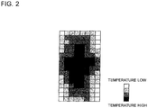
- the terminal 8 can also display a grid square map (image data) representing the temperature distribution in the space to be air-conditioned, according to the detection data of the space to be air-conditioned received from the controller 1 (see Fig. 2 ).
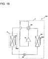
- the air-conditioning apparatus 100 includes the indoor unit 5 and the outdoor unit 7.
- the air-conditioning apparatus 100 includes a compressor 51 that compresses refrigerant, and a flow switching valve 52 that switches the flow path of the refrigerant.
- the air-conditioning apparatus 100 also includes an indoor heat exchanger 53 that serves as an evaporator or a condenser, an outdoor heat exchanger 55 that serves as a condenser or an evaporator, an indoor fan 53A that supplies air to the indoor heat exchanger 53, and an outdoor fan 55A that supplies air to the outdoor heat exchanger 55.
- the air-conditioning apparatus 100 includes an expansion device 54 that depressurizes the refrigerant.
- the indoor unit 5 includes the indoor heat exchanger 53 and the indoor fan 53A.
- the outdoor unit 7 includes the compressor 51, the flow switching valve 52, the outdoor heat exchanger 55, the expansion device 54, and the outdoor fan 55A.
- the air-conditioning apparatus 100 can switch between a cooling operation and a heating operation, by switching the flow switching valve 52.
- Fig. 1B illustrates a setting for the heating operation.
- Fig. 1C is a functional block diagram of the air-conditioning system 500 according to Embodiment.
- Fig. 2 is a grid square map generated by the air-conditioning system 500 according to Embodiment.
- the indoor unit 5 of the air-conditioning apparatus 100 includes an operation control unit 10, a determination unit 11, a test run switch SW, a memory Me, a reception unit 12, and a transmission unit 13.
- the operation control unit 10 controls the actuators according to results of determination of the determination unit 11 and the data related to operation instructions transmitted from the controller 1.
- the operation control unit 10 controls, for example, the rotation speed of the outdoor fan 55A and the indoor fan 53A, the opening degree of the expansion device 54, the frequency of the compressor 51, and the switching of the flow switching valve 52.
- the operation control unit 10 controls the actuators so as to perform predetermined actions, when the determination unit 11 determines that the test run switch SW has been pressed.
- the determination unit 11 determines whether or not a part of the space to be air-conditioned is cooled or heated, for example according to the detection data of the radiation temperature sensor 9. The determination unit 11 also decides whether the test run switch SW is pressed.
- the test run switch SW is attached, for example, to the indoor unit 5.
- the air-conditioning apparatus 100 performs a predetermined operation.
- the predetermined operation includes an air-sending operation in which only the indoor fan 53A is activated, and the cooling operation or the heating operation in which the compressor 51, the indoor fan 53A, the outdoor fan 55A, the expansion device 54, and the flow switching valve 52 are activated.
- the memory Me stores therein various types of data.
- the memory Me stores, for example, the detection data from the radiation temperature sensor 9.
- the memory Me can store operation data of the air-conditioning apparatus 100 such as a target temperature, data indicating the model of the air-conditioning apparatus 100, operation data of the air-conditioning apparatus 100 such as the duration of the operation, and the power consumption and rotation speed of the compressor 51 of the outdoor unit 7, the code indicating the cause of failure of the air-conditioning apparatus 100, and data of outside temperature.
- the reception unit 12 receives the data from the controller 1.
- the transmission unit 13 transmits the data to the controller 1.
- the controller 1 outputs, upon being operated by the user, the instruction for the cooling or heating operation to the air-conditioning apparatus 100.
- the controller 1 stores a plurality of pieces of detection data, out of which the controller 1 transmits the detection data according to a request from the terminal 8.
- the controller 1 includes a transmission unit 14 that transmits the data to the reception unit 12 of the air-conditioning apparatus 100, and a reception unit 15 that receives the data from the transmission unit 13 of the air-conditioning apparatus 100.
- the controller 1 also includes a determination unit 22 that decides whether a test run operation instruction has been received from the terminal 8, and a memory 23 that stores various types of data.
- the transmission unit 14 of the controller 1 can also transmit the data to the terminal 8, and the reception unit 15 can also receive the data from the terminal 8.
- the controller 1 Upon receipt of the operation instruction from the terminal 8, the controller 1 transmits the detection data received from the indoor unit 5 in advance of the test run to the terminal 8, and then causes the air-conditioning apparatus 100 to perform the test run.
- the controller 1 acquires the detection data after the test run, from the indoor unit 5. Further, the controller 1 transmits the detection data acquired from the indoor unit 5 after the test run, to the terminal 8.
- the terminal 8 detects a change between the detection data before the test run and the detection data after the test run, and outputs the change.
- the terminal 8 includes a reception unit 16 that receives the data from the controller 1, and a transmission unit 17 that transmits the data to the controller 1.
- the terminal 8 also includes a change detection unit 18 that detects a change in the detection data transmitted from the controller 1, and a data generation unit 19 that generates a grid square map according to the detection data received through the reception unit 16.
- the terminal 8 may be exemplified by a mobile phone (portable terminal) such as a smartphone, which includes a display unit 20.
- the terminal 8 also includes a memory 21 that stores various types of data.
- the terminal 8 receives, upon being operated by a service person, the instruction to cause the air-conditioning apparatus 100 to start the test run, and transmits the instruction data to the air-conditioning apparatus 100 through the controller 1.
- the change detection unit 18 is configured to detect whether a change has taken place, through comparison of the detection data sequentially acquired.
- the change detection unit 18 detects whether the air-conditioning apparatus 100 is normally operating, on the basis of a difference in the detection data from the radiation temperature sensor 9, or deviation of the differences in the detection data.
- the data generation unit 19 is configured to generate image data on the basis of the detection data of the radiation temperature sensor 9 received from the controller 1 through the reception unit 16.
- the image data is displayed on the display unit 20 in the form of the grid square map shown in Fig. 2 .
- the image data represents the temperature distribution in the space to be air-conditioned. In Fig. 2 , the higher the temperature is, the darker the shade is.
- the terminal 8 includes the memory 21, in which a plurality of pieces of image data can be stored.
- the data generation unit 19 is also configured to sort out the plurality of pieces of image data generated from the detection data according to the order of receipt from the controller 1. Accordingly, the grid square map representing the image data generated by the data generation unit 19 can be displayed on the display unit 20 on a time series basis.
- the time-series display may be in a form of a list, or in a form of slide-show.
- the grid square map generated by the data generation unit 19 can be displayed on the display unit 20. Therefore, the service person can recognize, in view of the terminal 8, the temperature distribution in the space to be air-conditioned.
- the operation control unit 10 and the determination unit 11 may be constituted of a control device.
- the change detection unit 18 and the data generation unit 19 may also be constituted of a control device.
- the control device may be constituted of, for example, dedicated hardware, or a central processing unit (CPU), also called, an arithmetic unit, a microprocessor, a processor, or a microcomputer, which executes a program stored in a memory.
- Examples of the dedicated hardware serving as the controller include a single circuit, a composite circuit, an application specific integrated circuit (ASIC), a field-programmable gate array (FPGA), and a combination thereof.
- ASIC application specific integrated circuit
- FPGA field-programmable gate array
- Each of the functional units of the control device may be realized by individual hardware, or the functional units may be realized by a single piece of hardware.
- the functions to be performed by the control device are realized by software, firmware, or a combination of the software and the firmware.
- the software and the firmware are described as a program and stored in a memory.
- the CPU realizes the functions of the control device by reading out and executing the program stored in the memory.
- Examples of the memory include a volatile or nonvolatile semiconductor memory, such as a RAM, a ROM, a flash memory, an EPROM, or an EEPROM.
- a part of the functions of the control device may be realized by the dedicated hardware, and another part may be realized by the software or the firmware.
- Fig. 3 is a sequence chart showing an operation of the air-conditioning system 500 according to Embodiment.
- the terminal 8 transmits request instruction data for the detection data and test run instruction data to the controller 1 (S1).
- the controller 1 transmits the request instruction data and the test run instruction data received from the terminal 8, to the indoor unit 5 (S2).
- the operation control unit 10 controls the corresponding actuators according to the test run instruction data (S3).
- the air-conditioning apparatus 100 activates the indoor fan 53A to perform the air-sending operation.
- the operation control unit 10 also controls the motor of the radiation temperature sensor 9, according to the request instruction data.
- the radiation temperature sensor 9 is made to rotate 360 degrees.
- the radiation temperature sensor 9 acquires the detection data from the range of 360 degrees.
- the indoor unit 5 transmits the detection data to the controller 1, (S4).
- the controller 1 transmits the detection data received from the indoor unit 5, to the terminal 8 (S5).
- the data generation unit 19 of the terminal 8 generates the image data (S6).
- the target temperature of the cooling operation may be set, for example, to 25 degrees Celsius.
- the indoor unit 5 Since the indoor unit 5 already received the request instruction data, the indoor unit 5 transmits the detection data to the controller 1 (S8).
- the controller 1 transmits the detection data received from the indoor unit 5, to the terminal 8 (S9).
- the data generation unit 19 of the terminal 8 generates the image data (S6).
- the indoor unit 5 received the test run instruction data at S2, performs the heating operation following the cooling operation (S11).
- the target temperature of the heating operation may be set, for example, to 25 degrees Celsius.
- the indoor unit 5 Since the indoor unit 5 already received the request instruction data, the indoor unit 5 transmits the detection data to the controller 1 (S12).
- the controller 1 transmits the detection data received from the indoor unit 5, to the terminal 8 (S13).
- the data generation unit 19 of the terminal 8 generates the image data (S14).
- the terminal 8 Upon completing the acquisition of the detection data from the test run of the air-conditioning apparatus 100, the terminal 8 transmits operation finish instruction data to the controller 1 (S15).
- the controller 1 transmits the operation finish instruction data received from the terminal 8, to the indoor unit 5 (S16).
- the controller 1 sequentially transmits the detection data (array data) received from the indoor unit 5, to the terminal 8.
- the control process through which the test run switch SW is turned on and the detection data acquired before the test run switch SW was turned on is transmitted to the controller 1, is omitted from Fig. 3 .
- the indoor unit 5 may transmit, before S3, the detection data already received before the test run switch SW was turned on to the controller 1, and the controller 1 may transmit the same detection data to the terminal 8.
- the change detection unit 18 of the terminal 8 compares the detection data which has been sequentially acquired, to detect whether there has been a change.
- the change detection unit 18 can detect that the air-conditioning apparatus 100 is not properly operating, for example, when the change is larger than a predetermined value.
- the detection result of the change detection unit 18 is, for example, displayed on the display unit 20, and transmitted to the service store 90.
- the terminal 8 converts the array data into the image data, and displays the image data on the display unit 20.
- the service person can visually confirm the transition of the radiation temperature in the space to be air-conditioned by viewing the slide show of the displayed image.
- the service person can confirm the transition of the radiation temperature not only from the detection result of the change detection unit 18, but also by viewing the grid square map on the display unit 20.
- the controller 1 instead of the controller 1 alleviates the restriction on the operation speed of the CPU, memory capacity, and so forth. That is, the display of the image data and the analysis of the detection data can be performed at a higher speed, and the storage capacity of the image data and the detection data can be increased.
- the value obtained by dividing the data amount of the radiation temperature sensor 9 by the data acquisition interval is set to a sufficiently smaller value than the communication rate between the indoor unit 5 and the controller 1, as well as between the controller 1 and the terminal 8.
- the terminal 8 of the air-conditioning system 500 detects the change between the detection data before the test run and the detection data after the test run, and outputs the change.
- the test run may be performed, for example, at the time of repair, inspection, installation, or replacement of the air-conditioning apparatus 100.
- the air-conditioning system 500 therefore, such malfunctions that a part of the space to be air-conditioned is not sufficiently cooled or heated, and that the temperature distribution in the space to be air-conditioned is uneven can be notified to the service person through the output (display or sound) from the terminal 8.
- the terminal 8 outputs a display
- the terminal 8 displays the region in the space to be air-conditioned that is insufficiently cooled.
- the air-conditioning apparatus 100 normally performs through the test run, after the repair, inspection, installation, or replacement of the air-conditioning apparatus 100, actually the foregoing malfunctions may take place owing to the defective installation work of the air-conditioning apparatus 100, or insufficient capacity thereof.
- the air-conditioning system 500 allows such malfunctions to be outputted from the terminal 8 thus to be notified to the service person. Accordingly, the service person carrying the terminal 8 can easily recognize whether it is necessary to perform further repair or inspection, or whether the air-conditioning apparatus 100 has to be replaced because of insufficient capacity.
- the service store also acquires the radiation temperature data transmitted from the terminal 8, and hence can easily recognize whether it is necessary to perform further repair or inspection.
- the air-conditioning system 500 according to Embodiment enables more precise decision to be made regarding whether the air-conditioning apparatus 100 has to undergo a repair, an inspection, or replacement.
- Fig. 4 is a sequence chart showing a modification of the operation of the air-conditioning system 500 according to Embodiment.
- test run instruction data from the terminal 8 serves as a trigger for starting the test run, however in the variation of Embodiment the test run switch SW provided on the indoor unit 5 serves as the trigger for starting the test run.
- the indoor unit 5 includes the test run switch SW for causing the air-conditioning apparatus 100 to perform the test run.
- the indoor unit 5 transmits the detection data acquired before the test run switch SW was turned on, to the controller 1.
- the indoor unit 5 also transmits the detection data acquired after the test run was started to the controller 1, when a predetermined time has elapsed after the start of the test run.
- the terminal 8 detects the change between the detection data acquired before the test run switch SW was turned on and the detection data acquired after the start of the test run, and outputs the change.
- Conventional air-conditioning apparatuses are not configured to transmit the data from the indoor unit to the controller when the test run switch is turned on. This is because it suffices for the service person to visually confirm that predetermined operations, for example the operation of the indoor fan, are normally performed, after the test run switch is turned on.
- the detection data is transmitted from the indoor unit 5 to the controller 1, so that the detection data is transmitted to the terminal 8 for confirmation therewith of whether the foregoing malfunctions are observed.
- the indoor unit 5 transmits switch-on data to the controller 1 (S20).
- the controller 1 transmits the switch-on data received from the indoor unit 5 to the terminal 8 (S21).
- the terminal 8 Upon receipt of the switch-on data, the terminal 8 transmits the request instruction data for the detection data to the controller 1 (S22).
- the controller 1 transmits the request instruction data received from the terminal 8 to the indoor unit 5 (S23).
- the terminal 8 is exempted from transmitting the test run instruction data at S22 and S23, because the air-conditioning apparatus 100 can recognize that the test run instruction has been issued, when the test run switch SW is pressed.
- the controller 1 may keep periodical logs, irrespective of whether the controller 1 is connected to the terminal 8. In other words, the controller 1 may periodically acquire the detection data from the indoor unit 5 during the test run of the air-conditioning apparatus 100, and store the detection data.
- the mentioned log keeping is represented by SS in Fig. 4 . It may be optionally determined whether to perform the process of SS. The log keeping may be performed between S29 and S30, or between S33 and S34.
- the log may be stored together with the control status of the air-conditioning operation, and may include the detection data itself from the radiation temperature sensor 9, or statistical values of the radiation temperature such as the average, maximum value, minimum value, and standard deviation. In the case of the latter, the data of a week or a month can be recorded provided that the controller 1 has a sufficient memory capacity, and the recorded data can be retrieved when the terminal 8 is connected.
- the controller 1 may only store the status immediately after the test run and a latest status (statistical values of the radiation temperature, such as the average, maximum value, minimum value, and standard deviation), to thereby detect a change in radiation temperature during the test run, by calculating the differences.
- the control process, through which the test run switch SW is turned on and the detection data acquired before the test run switch SW was turned on is transmitted to the controller 1, is omitted from Fig. 4 .
- the indoor unit 5 may transmit, before S24, the detection data already received before the test run switch SW was turned on to the controller 1, and the controller 1 may transmit the same detection data to the terminal 8.
Landscapes
- Engineering & Computer Science (AREA)
- General Engineering & Computer Science (AREA)
- Chemical & Material Sciences (AREA)
- Combustion & Propulsion (AREA)
- Mechanical Engineering (AREA)
- Signal Processing (AREA)
- Human Computer Interaction (AREA)
- Physics & Mathematics (AREA)
- Fuzzy Systems (AREA)
- Mathematical Physics (AREA)
- General Physics & Mathematics (AREA)
- Automation & Control Theory (AREA)
- Air Conditioning Control Device (AREA)
Applications Claiming Priority (1)
| Application Number | Priority Date | Filing Date | Title |
|---|---|---|---|
| PCT/JP2016/056266 WO2017149660A1 (fr) | 2016-03-01 | 2016-03-01 | Système de climatisation |
Publications (3)
| Publication Number | Publication Date |
|---|---|
| EP3232132A1 true EP3232132A1 (fr) | 2017-10-18 |
| EP3232132A4 EP3232132A4 (fr) | 2017-11-29 |
| EP3232132B1 EP3232132B1 (fr) | 2019-04-24 |
Family
ID=59742600
Family Applications (1)
| Application Number | Title | Priority Date | Filing Date |
|---|---|---|---|
| EP16865275.8A Active EP3232132B1 (fr) | 2016-03-01 | 2016-03-01 | Système de climatisation |
Country Status (6)
| Country | Link |
|---|---|
| US (1) | US20190003735A1 (fr) |
| EP (1) | EP3232132B1 (fr) |
| JP (1) | JP6625196B2 (fr) |
| CN (1) | CN108700320B (fr) |
| AU (1) | AU2016395065B2 (fr) |
| WO (1) | WO2017149660A1 (fr) |
Families Citing this family (3)
| Publication number | Priority date | Publication date | Assignee | Title |
|---|---|---|---|---|
| JP7269461B2 (ja) * | 2018-03-28 | 2023-05-09 | ダイキン工業株式会社 | 空気調和ユニットおよび空気質測定装置 |
| CN110749032B (zh) * | 2019-10-31 | 2021-08-31 | 广东美的制冷设备有限公司 | 运行控制方法、装置、空调器以及存储介质 |
| US12410932B2 (en) | 2022-06-30 | 2025-09-09 | Haier Us Appliance Solutions, Inc. | Air conditioning appliance and method for control |
Family Cites Families (14)
| Publication number | Priority date | Publication date | Assignee | Title |
|---|---|---|---|---|
| JP3933365B2 (ja) * | 2000-03-08 | 2007-06-20 | 三洋電機株式会社 | 空気調和装置のメンテナンスシステム |
| CN1167913C (zh) * | 2002-07-18 | 2004-09-22 | 上海交通大学 | 热舒适模糊控制空调器 |
| JP4225137B2 (ja) * | 2003-06-27 | 2009-02-18 | ダイキン工業株式会社 | 空気調和装置の室内パネル及び空気調和装置 |
| KR100664056B1 (ko) * | 2004-10-26 | 2007-01-03 | 엘지전자 주식회사 | 멀티형 공기조화기의 고장유무 판별장치 및 방법 |
| JP2009014233A (ja) * | 2007-07-03 | 2009-01-22 | Hitachi Appliances Inc | 空気調和機、及び空気調和機の管理システム |
| JP2011141081A (ja) * | 2010-01-07 | 2011-07-21 | Mitsubishi Heavy Ind Ltd | 空調監視システム及びその制御方法、空気調和機、並びに集中監視装置 |
| JP5258816B2 (ja) * | 2010-02-27 | 2013-08-07 | 三菱電機株式会社 | 空気調和機 |
| JP6091243B2 (ja) * | 2013-02-18 | 2017-03-08 | 三菱電機株式会社 | 空気調和機 |
| JP6261295B2 (ja) * | 2013-11-20 | 2018-01-17 | 日立ジョンソンコントロールズ空調株式会社 | 空気調和システム |
| US9581985B2 (en) * | 2014-02-21 | 2017-02-28 | Johnson Controls Technology Company | Systems and methods for auto-commissioning and self-diagnostics |
| CN104896685B (zh) * | 2014-03-03 | 2019-06-28 | 松下电器(美国)知识产权公司 | 传感方法、传感系统及包含它们的空调设备 |
| JP6150750B2 (ja) * | 2014-03-12 | 2017-06-21 | 三菱電機株式会社 | 室内機及び空気調和装置 |
| JP6303731B2 (ja) * | 2014-03-31 | 2018-04-04 | ダイキン工業株式会社 | 温熱環境再現システム |
| JP6334262B2 (ja) * | 2014-05-27 | 2018-05-30 | 三菱電機株式会社 | 空気調和機 |
-
2016
- 2016-03-01 JP JP2018502909A patent/JP6625196B2/ja active Active
- 2016-03-01 WO PCT/JP2016/056266 patent/WO2017149660A1/fr not_active Ceased
- 2016-03-01 AU AU2016395065A patent/AU2016395065B2/en active Active
- 2016-03-01 US US16/064,036 patent/US20190003735A1/en not_active Abandoned
- 2016-03-01 CN CN201680082439.0A patent/CN108700320B/zh active Active
- 2016-03-01 EP EP16865275.8A patent/EP3232132B1/fr active Active
Also Published As
| Publication number | Publication date |
|---|---|
| JPWO2017149660A1 (ja) | 2018-09-27 |
| AU2016395065A1 (en) | 2018-07-26 |
| US20190003735A1 (en) | 2019-01-03 |
| JP6625196B2 (ja) | 2019-12-25 |
| WO2017149660A1 (fr) | 2017-09-08 |
| AU2016395065B2 (en) | 2019-08-22 |
| EP3232132A4 (fr) | 2017-11-29 |
| EP3232132B1 (fr) | 2019-04-24 |
| CN108700320A (zh) | 2018-10-23 |
| CN108700320B (zh) | 2020-08-21 |
Similar Documents
| Publication | Publication Date | Title |
|---|---|---|
| US11635222B2 (en) | Damper fault detection | |
| EP2913598B1 (fr) | Climatiseur et son procédé de fonctionnement | |
| US10422544B2 (en) | Information notification method and relocation determination device | |
| EP3406984B1 (fr) | Système de gestion d'informations de dispositif | |
| JP6355850B2 (ja) | 判定支援装置、判定支援方法及びプログラム | |
| US20170082309A1 (en) | Air-conditioning system | |
| WO2017199373A1 (fr) | Climatiseur | |
| EP3232132B1 (fr) | Système de climatisation | |
| WO2017189430A1 (fr) | Extraction d'informations à base de localisation, visualisation et diagnostic pour des systèmes de réfrigération, cvc et d'autres systèmes de bâtiment | |
| EP3214384B1 (fr) | Télécommande pour système de climatisation | |
| KR102206461B1 (ko) | 공기조화기 시스템 및 그 동작방법 | |
| US20190120516A1 (en) | Systems and methods for mitigating ice formation conditions in air conditioning systems | |
| US20140167970A1 (en) | Refrigerant Charge Level Detection | |
| EP3879197A1 (fr) | Dispositif de commande de climatisation, dispositif de commande de circuit de réfrigérant, procédé de contrôle, et programme | |
| US12031736B2 (en) | Inspection execution method, management server, mobile terminal, and refrigerant cycle apparatus | |
| US10495338B2 (en) | Remote controller setting device | |
| WO2023148866A1 (fr) | Système de pompe à chaleur et système de commande | |
| US11339986B2 (en) | Remote controller and air-conditioning apparatus | |
| US20150253031A1 (en) | Air-conditioning apparatus | |
| CN114902003B (zh) | 空调系统 | |
| KR200408306Y1 (ko) | 타이머 컨트롤러 | |
| WO2018127969A1 (fr) | Système de source de chaleur | |
| KR101852824B1 (ko) | 공기조화장치의 제어방법 | |
| KR20060039590A (ko) | 공기 조화기 및 그 제어 방법 |
Legal Events
| Date | Code | Title | Description |
|---|---|---|---|
| STAA | Information on the status of an ep patent application or granted ep patent |
Free format text: STATUS: UNKNOWN |
|
| STAA | Information on the status of an ep patent application or granted ep patent |
Free format text: STATUS: THE INTERNATIONAL PUBLICATION HAS BEEN MADE |
|
| PUAI | Public reference made under article 153(3) epc to a published international application that has entered the european phase |
Free format text: ORIGINAL CODE: 0009012 |
|
| STAA | Information on the status of an ep patent application or granted ep patent |
Free format text: STATUS: REQUEST FOR EXAMINATION WAS MADE |
|
| 17P | Request for examination filed |
Effective date: 20170524 |
|
| AK | Designated contracting states |
Kind code of ref document: A1 Designated state(s): AL AT BE BG CH CY CZ DE DK EE ES FI FR GB GR HR HU IE IS IT LI LT LU LV MC MK MT NL NO PL PT RO RS SE SI SK SM TR |
|
| AX | Request for extension of the european patent |
Extension state: BA ME |
|
| RIN1 | Information on inventor provided before grant (corrected) |
Inventor name: KOIZUMI, YOSHIAKI Inventor name: KOJIMA, YOSHIHISA Inventor name: MURAMATSU, HIDETOSHI |
|
| A4 | Supplementary search report drawn up and despatched |
Effective date: 20171030 |
|
| RIC1 | Information provided on ipc code assigned before grant |
Ipc: G08B 21/18 20060101ALI20171024BHEP Ipc: F24F 11/02 20060101AFI20171024BHEP Ipc: G08B 25/08 20060101ALI20171024BHEP Ipc: F24F 11/00 20060101ALI20171024BHEP |
|
| REG | Reference to a national code |
Ref country code: DE Ref legal event code: R079 Ref document number: 602016012990 Country of ref document: DE Free format text: PREVIOUS MAIN CLASS: F24F0011020000 Ipc: F24F0011300000 |
|
| RIC1 | Information provided on ipc code assigned before grant |
Ipc: F24F 11/62 20180101ALI20180718BHEP Ipc: F24F 11/30 20180101AFI20180718BHEP |
|
| GRAP | Despatch of communication of intention to grant a patent |
Free format text: ORIGINAL CODE: EPIDOSNIGR1 |
|
| STAA | Information on the status of an ep patent application or granted ep patent |
Free format text: STATUS: GRANT OF PATENT IS INTENDED |
|
| DAX | Request for extension of the european patent (deleted) | ||
| INTG | Intention to grant announced |
Effective date: 20181016 |
|
| GRAS | Grant fee paid |
Free format text: ORIGINAL CODE: EPIDOSNIGR3 |
|
| RIC1 | Information provided on ipc code assigned before grant |
Ipc: F24F 11/62 20180101ALI20180718BHEP Ipc: F24F 11/30 20180101AFI20180718BHEP |
|
| GRAA | (expected) grant |
Free format text: ORIGINAL CODE: 0009210 |
|
| STAA | Information on the status of an ep patent application or granted ep patent |
Free format text: STATUS: THE PATENT HAS BEEN GRANTED |
|
| AK | Designated contracting states |
Kind code of ref document: B1 Designated state(s): AL AT BE BG CH CY CZ DE DK EE ES FI FR GB GR HR HU IE IS IT LI LT LU LV MC MK MT NL NO PL PT RO RS SE SI SK SM TR |
|
| DAV | Request for validation of the european patent (deleted) | ||
| REG | Reference to a national code |
Ref country code: GB Ref legal event code: FG4D |
|
| REG | Reference to a national code |
Ref country code: CH Ref legal event code: EP |
|
| REG | Reference to a national code |
Ref country code: DE Ref legal event code: R096 Ref document number: 602016012990 Country of ref document: DE |
|
| REG | Reference to a national code |
Ref country code: AT Ref legal event code: REF Ref document number: 1124610 Country of ref document: AT Kind code of ref document: T Effective date: 20190515 Ref country code: IE Ref legal event code: FG4D |
|
| REG | Reference to a national code |
Ref country code: NL Ref legal event code: MP Effective date: 20190424 |
|
| REG | Reference to a national code |
Ref country code: LT Ref legal event code: MG4D |
|
| PG25 | Lapsed in a contracting state [announced via postgrant information from national office to epo] |
Ref country code: NL Free format text: LAPSE BECAUSE OF FAILURE TO SUBMIT A TRANSLATION OF THE DESCRIPTION OR TO PAY THE FEE WITHIN THE PRESCRIBED TIME-LIMIT Effective date: 20190424 |
|
| PG25 | Lapsed in a contracting state [announced via postgrant information from national office to epo] |
Ref country code: AL Free format text: LAPSE BECAUSE OF FAILURE TO SUBMIT A TRANSLATION OF THE DESCRIPTION OR TO PAY THE FEE WITHIN THE PRESCRIBED TIME-LIMIT Effective date: 20190424 Ref country code: PT Free format text: LAPSE BECAUSE OF FAILURE TO SUBMIT A TRANSLATION OF THE DESCRIPTION OR TO PAY THE FEE WITHIN THE PRESCRIBED TIME-LIMIT Effective date: 20190824 Ref country code: ES Free format text: LAPSE BECAUSE OF FAILURE TO SUBMIT A TRANSLATION OF THE DESCRIPTION OR TO PAY THE FEE WITHIN THE PRESCRIBED TIME-LIMIT Effective date: 20190424 Ref country code: SE Free format text: LAPSE BECAUSE OF FAILURE TO SUBMIT A TRANSLATION OF THE DESCRIPTION OR TO PAY THE FEE WITHIN THE PRESCRIBED TIME-LIMIT Effective date: 20190424 Ref country code: HR Free format text: LAPSE BECAUSE OF FAILURE TO SUBMIT A TRANSLATION OF THE DESCRIPTION OR TO PAY THE FEE WITHIN THE PRESCRIBED TIME-LIMIT Effective date: 20190424 Ref country code: FI Free format text: LAPSE BECAUSE OF FAILURE TO SUBMIT A TRANSLATION OF THE DESCRIPTION OR TO PAY THE FEE WITHIN THE PRESCRIBED TIME-LIMIT Effective date: 20190424 Ref country code: NO Free format text: LAPSE BECAUSE OF FAILURE TO SUBMIT A TRANSLATION OF THE DESCRIPTION OR TO PAY THE FEE WITHIN THE PRESCRIBED TIME-LIMIT Effective date: 20190724 Ref country code: LT Free format text: LAPSE BECAUSE OF FAILURE TO SUBMIT A TRANSLATION OF THE DESCRIPTION OR TO PAY THE FEE WITHIN THE PRESCRIBED TIME-LIMIT Effective date: 20190424 |
|
| PG25 | Lapsed in a contracting state [announced via postgrant information from national office to epo] |
Ref country code: RS Free format text: LAPSE BECAUSE OF FAILURE TO SUBMIT A TRANSLATION OF THE DESCRIPTION OR TO PAY THE FEE WITHIN THE PRESCRIBED TIME-LIMIT Effective date: 20190424 Ref country code: PL Free format text: LAPSE BECAUSE OF FAILURE TO SUBMIT A TRANSLATION OF THE DESCRIPTION OR TO PAY THE FEE WITHIN THE PRESCRIBED TIME-LIMIT Effective date: 20190424 Ref country code: GR Free format text: LAPSE BECAUSE OF FAILURE TO SUBMIT A TRANSLATION OF THE DESCRIPTION OR TO PAY THE FEE WITHIN THE PRESCRIBED TIME-LIMIT Effective date: 20190725 Ref country code: LV Free format text: LAPSE BECAUSE OF FAILURE TO SUBMIT A TRANSLATION OF THE DESCRIPTION OR TO PAY THE FEE WITHIN THE PRESCRIBED TIME-LIMIT Effective date: 20190424 Ref country code: BG Free format text: LAPSE BECAUSE OF FAILURE TO SUBMIT A TRANSLATION OF THE DESCRIPTION OR TO PAY THE FEE WITHIN THE PRESCRIBED TIME-LIMIT Effective date: 20190724 |
|
| REG | Reference to a national code |
Ref country code: AT Ref legal event code: MK05 Ref document number: 1124610 Country of ref document: AT Kind code of ref document: T Effective date: 20190424 |
|
| PG25 | Lapsed in a contracting state [announced via postgrant information from national office to epo] |
Ref country code: IS Free format text: LAPSE BECAUSE OF FAILURE TO SUBMIT A TRANSLATION OF THE DESCRIPTION OR TO PAY THE FEE WITHIN THE PRESCRIBED TIME-LIMIT Effective date: 20190824 |
|
| REG | Reference to a national code |
Ref country code: DE Ref legal event code: R097 Ref document number: 602016012990 Country of ref document: DE |
|
| PG25 | Lapsed in a contracting state [announced via postgrant information from national office to epo] |
Ref country code: AT Free format text: LAPSE BECAUSE OF FAILURE TO SUBMIT A TRANSLATION OF THE DESCRIPTION OR TO PAY THE FEE WITHIN THE PRESCRIBED TIME-LIMIT Effective date: 20190424 Ref country code: DK Free format text: LAPSE BECAUSE OF FAILURE TO SUBMIT A TRANSLATION OF THE DESCRIPTION OR TO PAY THE FEE WITHIN THE PRESCRIBED TIME-LIMIT Effective date: 20190424 Ref country code: SK Free format text: LAPSE BECAUSE OF FAILURE TO SUBMIT A TRANSLATION OF THE DESCRIPTION OR TO PAY THE FEE WITHIN THE PRESCRIBED TIME-LIMIT Effective date: 20190424 Ref country code: CZ Free format text: LAPSE BECAUSE OF FAILURE TO SUBMIT A TRANSLATION OF THE DESCRIPTION OR TO PAY THE FEE WITHIN THE PRESCRIBED TIME-LIMIT Effective date: 20190424 Ref country code: EE Free format text: LAPSE BECAUSE OF FAILURE TO SUBMIT A TRANSLATION OF THE DESCRIPTION OR TO PAY THE FEE WITHIN THE PRESCRIBED TIME-LIMIT Effective date: 20190424 Ref country code: RO Free format text: LAPSE BECAUSE OF FAILURE TO SUBMIT A TRANSLATION OF THE DESCRIPTION OR TO PAY THE FEE WITHIN THE PRESCRIBED TIME-LIMIT Effective date: 20190424 |
|
| PG25 | Lapsed in a contracting state [announced via postgrant information from national office to epo] |
Ref country code: IT Free format text: LAPSE BECAUSE OF FAILURE TO SUBMIT A TRANSLATION OF THE DESCRIPTION OR TO PAY THE FEE WITHIN THE PRESCRIBED TIME-LIMIT Effective date: 20190424 Ref country code: SM Free format text: LAPSE BECAUSE OF FAILURE TO SUBMIT A TRANSLATION OF THE DESCRIPTION OR TO PAY THE FEE WITHIN THE PRESCRIBED TIME-LIMIT Effective date: 20190424 |
|
| PLBE | No opposition filed within time limit |
Free format text: ORIGINAL CODE: 0009261 |
|
| STAA | Information on the status of an ep patent application or granted ep patent |
Free format text: STATUS: NO OPPOSITION FILED WITHIN TIME LIMIT |
|
| PG25 | Lapsed in a contracting state [announced via postgrant information from national office to epo] |
Ref country code: TR Free format text: LAPSE BECAUSE OF FAILURE TO SUBMIT A TRANSLATION OF THE DESCRIPTION OR TO PAY THE FEE WITHIN THE PRESCRIBED TIME-LIMIT Effective date: 20190424 |
|
| 26N | No opposition filed |
Effective date: 20200127 |
|
| PG25 | Lapsed in a contracting state [announced via postgrant information from national office to epo] |
Ref country code: SI Free format text: LAPSE BECAUSE OF FAILURE TO SUBMIT A TRANSLATION OF THE DESCRIPTION OR TO PAY THE FEE WITHIN THE PRESCRIBED TIME-LIMIT Effective date: 20190424 |
|
| PG25 | Lapsed in a contracting state [announced via postgrant information from national office to epo] |
Ref country code: MC Free format text: LAPSE BECAUSE OF FAILURE TO SUBMIT A TRANSLATION OF THE DESCRIPTION OR TO PAY THE FEE WITHIN THE PRESCRIBED TIME-LIMIT Effective date: 20190424 |
|
| REG | Reference to a national code |
Ref country code: CH Ref legal event code: PL |
|
| REG | Reference to a national code |
Ref country code: BE Ref legal event code: MM Effective date: 20200331 |
|
| PG25 | Lapsed in a contracting state [announced via postgrant information from national office to epo] |
Ref country code: LU Free format text: LAPSE BECAUSE OF NON-PAYMENT OF DUE FEES Effective date: 20200301 |
|
| PG25 | Lapsed in a contracting state [announced via postgrant information from national office to epo] |
Ref country code: CH Free format text: LAPSE BECAUSE OF NON-PAYMENT OF DUE FEES Effective date: 20200331 Ref country code: FR Free format text: LAPSE BECAUSE OF NON-PAYMENT OF DUE FEES Effective date: 20200331 Ref country code: IE Free format text: LAPSE BECAUSE OF NON-PAYMENT OF DUE FEES Effective date: 20200301 Ref country code: LI Free format text: LAPSE BECAUSE OF NON-PAYMENT OF DUE FEES Effective date: 20200331 |
|
| PG25 | Lapsed in a contracting state [announced via postgrant information from national office to epo] |
Ref country code: BE Free format text: LAPSE BECAUSE OF NON-PAYMENT OF DUE FEES Effective date: 20200331 |
|
| REG | Reference to a national code |
Ref country code: DE Ref legal event code: R084 Ref document number: 602016012990 Country of ref document: DE |
|
| PG25 | Lapsed in a contracting state [announced via postgrant information from national office to epo] |
Ref country code: MT Free format text: LAPSE BECAUSE OF FAILURE TO SUBMIT A TRANSLATION OF THE DESCRIPTION OR TO PAY THE FEE WITHIN THE PRESCRIBED TIME-LIMIT Effective date: 20190424 Ref country code: CY Free format text: LAPSE BECAUSE OF FAILURE TO SUBMIT A TRANSLATION OF THE DESCRIPTION OR TO PAY THE FEE WITHIN THE PRESCRIBED TIME-LIMIT Effective date: 20190424 |
|
| REG | Reference to a national code |
Ref country code: GB Ref legal event code: 746 Effective date: 20220509 |
|
| PG25 | Lapsed in a contracting state [announced via postgrant information from national office to epo] |
Ref country code: MK Free format text: LAPSE BECAUSE OF FAILURE TO SUBMIT A TRANSLATION OF THE DESCRIPTION OR TO PAY THE FEE WITHIN THE PRESCRIBED TIME-LIMIT Effective date: 20190424 |
|
| P01 | Opt-out of the competence of the unified patent court (upc) registered |
Effective date: 20230512 |
|
| PGFP | Annual fee paid to national office [announced via postgrant information from national office to epo] |
Ref country code: GB Payment date: 20260202 Year of fee payment: 11 |
|
| PGFP | Annual fee paid to national office [announced via postgrant information from national office to epo] |
Ref country code: DE Payment date: 20260128 Year of fee payment: 11 |