EP3232168A1 - Détermination du niveau de remplissage d'un milieu - Google Patents
Détermination du niveau de remplissage d'un milieu Download PDFInfo
- Publication number
- EP3232168A1 EP3232168A1 EP17158025.1A EP17158025A EP3232168A1 EP 3232168 A1 EP3232168 A1 EP 3232168A1 EP 17158025 A EP17158025 A EP 17158025A EP 3232168 A1 EP3232168 A1 EP 3232168A1
- Authority
- EP
- European Patent Office
- Prior art keywords
- container
- measuring device
- radar signal
- arrangement according
- radar
- Prior art date
- Legal status (The legal status is an assumption and is not a legal conclusion. Google has not performed a legal analysis and makes no representation as to the accuracy of the status listed.)
- Withdrawn
Links
- 238000011156 evaluation Methods 0.000 claims abstract description 12
- 238000005259 measurement Methods 0.000 claims description 14
- 239000012811 non-conductive material Substances 0.000 claims description 6
- 238000000034 method Methods 0.000 claims description 5
- 239000000523 sample Substances 0.000 description 5
- 230000008901 benefit Effects 0.000 description 4
- 230000004888 barrier function Effects 0.000 description 3
- 230000008859 change Effects 0.000 description 3
- 238000002592 echocardiography Methods 0.000 description 2
- 230000005540 biological transmission Effects 0.000 description 1
- 238000004140 cleaning Methods 0.000 description 1
- 230000006870 function Effects 0.000 description 1
- 238000009434 installation Methods 0.000 description 1
- 239000007788 liquid Substances 0.000 description 1
- 239000010808 liquid waste Substances 0.000 description 1
- 239000000463 material Substances 0.000 description 1
- 239000007769 metal material Substances 0.000 description 1
- 230000004048 modification Effects 0.000 description 1
- 238000012986 modification Methods 0.000 description 1
- 230000035515 penetration Effects 0.000 description 1
- 230000008569 process Effects 0.000 description 1
- 230000007704 transition Effects 0.000 description 1
- XLYOFNOQVPJJNP-UHFFFAOYSA-N water Substances O XLYOFNOQVPJJNP-UHFFFAOYSA-N 0.000 description 1
Images

Classifications
-
- G—PHYSICS
- G01—MEASURING; TESTING
- G01F—MEASURING VOLUME, VOLUME FLOW, MASS FLOW OR LIQUID LEVEL; METERING BY VOLUME
- G01F23/00—Indicating or measuring liquid level or level of fluent solid material, e.g. indicating in terms of volume or indicating by means of an alarm
- G01F23/22—Indicating or measuring liquid level or level of fluent solid material, e.g. indicating in terms of volume or indicating by means of an alarm by measuring physical variables, other than linear dimensions, pressure or weight, dependent on the level to be measured, e.g. by difference of heat transfer of steam or water
- G01F23/28—Indicating or measuring liquid level or level of fluent solid material, e.g. indicating in terms of volume or indicating by means of an alarm by measuring physical variables, other than linear dimensions, pressure or weight, dependent on the level to be measured, e.g. by difference of heat transfer of steam or water by measuring the variations of parameters of electromagnetic or acoustic waves applied directly to the liquid or fluent solid material
- G01F23/284—Electromagnetic waves
Definitions
- the invention relates to an arrangement with a container and a measuring device and a method for determining a level of a medium in the container according to the radar principle according to the preamble of claim 1 and 11, respectively.
- Level sensors according to the radar principle send a radar signal to the surface of the medium to be measured and evaluate the echoes.
- a disadvantage of the conventional level sensors is that they must be mounted directly in the container or at a designated opening so that the radar signal can propagate freely to the medium and back.
- a level gauge is known, the antenna is separated from the interior of the container by a microwave transparent plate. This plate is part of the antenna system and does not change the way of mounting and measuring the level gauge with the aforementioned disadvantages.
- the US 7,775,106 B2 discloses a level measurement, which is referred to as radar-based, but in reality based on a guided in a microwave probe and no radar radiated signal.
- the probe is mounted laterally on the container whose wall has a microwave-permeable window in the region of the probe. This is to prevent that the probe protrudes into the medium, so that measurements with media are possible, which would damage the probe.
- the DE 20 2013 103 563 U1 describes a level sensor which is designed as a microwave barrier with evaluation of the signal attenuation. Transmitter and receiver of the microwave barrier can also outside the container be arranged. However, such microwave barriers do not work according to the radar principle.
- the measuring device initially works as usual with a transmitter and a receiver which emit a radar signal in the direction of the medium by means of an antenna, generate a received signal from the echo of the radar signal and forward it to an evaluation unit which determines the fill level therefrom.
- This evaluation preferably determines the signal propagation time of the radar signal, resulting in the distance between the measuring device and the surface of the medium. From container geometry and position of the measuring device that is easily convertible to a level.
- the invention is based on the basic idea of not arranging the measuring device to the medium as conventionally with a free signal path. Rather, the measuring device is arranged with respect to the container so that there is a wall of the container between the measuring device and the container. This wall is non-conductive and is therefore irradiated by the radar signal. A conductive wall would shield the wave of the radar signal, and then the measurement will not work.
- the invention has the advantage that no direct introduction or attachment of the measuring device in or on the container is required.
- the container does not have to be opened or modified in any way for cooperation with the measuring device. Therefore, a structure or a change of arrangement is particularly easy.
- the advantage is particularly evident in small containers that are frequently replaced or emptied or filled by hand, as this no installation steps are necessary.
- the container can simply be removed or placed on the measuring device.
- the container is preferably closed. This means that there is no opening at all in the container in which a measuring device is mounted or could pass through a radar signal. However, it does not exclude any connections, for example for lines for filling or removing the medium.
- the container is preferably made of non-conductive material.
- the container is thus not only in the passage region of the radar signal, but a total of non-conductive or non-metallic, for example made of plastic. It is then not necessary to take into account in the arrangement of the measuring device consideration of the passage area, which may be anywhere on the container.
- the measuring device is preferably mounted without contact with the container. This further facilitates assembly and replacement of measuring device or container. However, it is also conceivable to introduce the container directly to the measuring device, without establishing a firm connection. Also conceivable is a common holding device in which the container and / or measuring device are detachably mounted. In any case, so the container can be easily replaced without dismantling the measuring device and vice versa, and a recalibration is therefore not required.
- the measuring device is preferably spaced from the container.
- the arrangement is thus not only contactless, but there is a significant mutual distance of for example one meter or more. As a result, the measuring device can interfere with the operations on the container even less.
- the measuring device is preferably arranged above the container. This is a frequent measuring position for level sensors, which is also possible according to the invention without a free signal path.
- the non-conductive wall in this case is the lid of the container or a part thereof.
- the measuring device can be arranged laterally to the container.
- the nonconductive wall in this case is a side wall or a part thereof.
- a preferred function in a lateral arrangement is the level guard for a certain level, such as full or empty containers.
- a lateral radar measurement is extremely difficult, if not impossible, because a lateral opening for the radar signal is needed and this, of course, must not lead to leakage of the medium from the container.
- the measuring device can be arranged below the container.
- the container is simply placed on the measuring device, which has a corresponding housing, which is protected, for example against splashes and the like and the antenna encapsulated in accordance with non-metallic material.
- the space required for mounting the measuring device is substantially reduced.
- the handling is particularly simple, because the measuring device can be designed so that it does not differ from the user of a simple filing for the user.
- a plurality of containers are provided, and the evaluation device is adapted to determine a plurality of levels in the plurality of containers.
- An intelligent multiple evaluation here means the least amount of equipment.
- the direction of the radar signal is variable, be it by physical movement of the antenna, directional antenna control or the use of multiple antennas for different directions.
- the evaluation unit is preferably designed to determine in a learning step, the transit time differences in the passage of the radar signal through the non-conductive wall of the passage region and to compensate during operation. This prevents that the wall penetrated by the radar signal falsifies the level measurement.
- This calibration can be done by an empty measurement, but also a parameterization, for example on the basis of an invoice with knowledge of the geometry and material of the container.
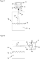
- FIG. 1 shows an arrangement of a measuring device for determining the level or a level sensor 10 according to the radar principle on a container 12 with a medium 14.
- the task of the level sensor 10 is to determine the position of the surface 16 of the medium 14 and thus its level.
- the level sensor 10 has a transmitter 18, an antenna 20 and a receiver 22. Transmitter 18 and receiver 22 may also be designed together as a transceiver. Thus, a radar signal 24 is emitted in the direction of the surface 16 and received its echo again. The radar signal 24 is preferably directed to suppress echoes not generated at the surface 16. The receiver 22 forwards the received signal generated by the radar signal to an evaluation unit 26. There the signal transit time between transmission and reception is determined in a manner known per se. In this way, the distance of the surface 16 is measured, from which by means of the position of the level sensor 10 relative to the container 12, the filling level and in known geometry of the container 12, the filling quantity can be determined.
- the container 12 is closed at least in the passage region 28 of the radar signal 24. There is thus no opening, but a wall of the container 28, in this case the lid.
- the passage region 28 is made of a non-conductive material.
- a kind of window made of non-conductive material but it may also consist of the entire lid or even the entire container 12 made of non-conductive material.
- a typical example of such a container is a plastic canister or bottle.
- the measurement of the level sensor 10 thus takes place through the container wall. This is possible because the radiated with the radar signal 24 propagates energy of a high frequency wave through non-conductive materials. Thus, the radiated wave can pass through the passage region 28 to the surface 16. There, the wave is reflected and propagates again through the passage area to the antenna 20. Due to the measurement in the closed container 12 into the can Level sensor 10 are mounted without contact and even at a greater distance from the container 12.
- the runtime error caused thereby is learned or parameterized in a calibration measurement and then corrected during operation in the evaluation unit 28.
- a preferred application is rather to smaller containers 12, for example a 10 liter canister into which, for example, a liquid waste product is introduced from a process.
- the canister When the canister is full, it can simply be dumped and returned or replaced with an empty canister. Steps such as removing or removing the level sensor 10, eliminating the need for cleaning and reassembly. Equally simple is the replacement of the level sensor 10.
- FIG. 2 shows an alternative arrangement of the level sensor 10 side of the container 12.
- the laterally arranged level sensor 10 can be used in particular as a guard for a certain level.
- a modification of the container 12, so the attachment of an opening or the like, is not required because the radar signal penetrates the passage region 28 of the container 12.
- FIG. 3 shows a further alternative arrangement in which the level sensor 10 is disposed below the container 12.
- the container 12 is placed on the level sensor 10. Therefore, in this embodiment, the antenna 20 is fully shown within the level sensor 10, this being the case for the other embodiments FIG. 1 or 2 it is also conceivable.
- a not shown interposed tray is conceivable, but should be non-conductive and preferably designed to be less attenuating.
- This arrangement of the level sensor 10 from below is particularly suitable for media 14 with low permittivity such as oil and virtually all liquids with low water content.
- the radar measurement first generates an echo at the bottom of the container 12 in the region of the wall 28, but this echo is mainly caused by the entry into the medium 14 and not by the wall 28. Another echo, that provides the actual reading, then arises at the surface 16 in the transition from medium 14 to the overlying air layer.
- a low permittivity of the medium 14 is useful because then, after the lower echo, there is still enough energy left to produce the strongest, easily evaluable echo at the surface 16.
Landscapes
- Physics & Mathematics (AREA)
- Electromagnetism (AREA)
- Thermal Sciences (AREA)
- Fluid Mechanics (AREA)
- General Physics & Mathematics (AREA)
- Measurement Of Levels Of Liquids Or Fluent Solid Materials (AREA)
Applications Claiming Priority (1)
| Application Number | Priority Date | Filing Date | Title |
|---|---|---|---|
| DE102016107049.1A DE102016107049B3 (de) | 2016-04-15 | 2016-04-15 | Bestimmen eines Füllstands eines Mediums |
Publications (1)
| Publication Number | Publication Date |
|---|---|
| EP3232168A1 true EP3232168A1 (fr) | 2017-10-18 |
Family
ID=58185364
Family Applications (1)
| Application Number | Title | Priority Date | Filing Date |
|---|---|---|---|
| EP17158025.1A Withdrawn EP3232168A1 (fr) | 2016-04-15 | 2017-02-27 | Détermination du niveau de remplissage d'un milieu |
Country Status (2)
| Country | Link |
|---|---|
| EP (1) | EP3232168A1 (fr) |
| DE (1) | DE102016107049B3 (fr) |
Cited By (1)
| Publication number | Priority date | Publication date | Assignee | Title |
|---|---|---|---|---|
| WO2021239260A1 (fr) * | 2020-05-29 | 2021-12-02 | Vega Grieshaber Kg | Dispositif de mesure optique de niveau de remplissage |
Families Citing this family (1)
| Publication number | Priority date | Publication date | Assignee | Title |
|---|---|---|---|---|
| DE102023203927A1 (de) | 2023-04-27 | 2024-10-31 | Vega Grieshaber Kg | Füllstandmessgerät zur Prozessautomatisierung im industriellen oder privaten Umfeld |
Citations (9)
| Publication number | Priority date | Publication date | Assignee | Title |
|---|---|---|---|---|
| DE19516789A1 (de) * | 1995-05-08 | 1996-11-14 | Stoeckert Instr Gmbh | Vorrichtung zur Überwachung des Füllstandes eines Vorratsbehälters |
| DE4407823C2 (de) | 1994-03-09 | 1997-12-11 | Grieshaber Vega Kg | Füllstandmeßgerät |
| DE19913530A1 (de) * | 1999-03-25 | 2000-09-28 | Ksb Ag | Niveauabhängige Steuerung von Pumpen |
| DE112006000738T5 (de) * | 2005-03-31 | 2008-03-06 | Agellis Group Ab | Verfahren zum Analysieren einer Substanz in einem Behälter |
| US7775106B2 (en) | 2008-02-01 | 2010-08-17 | Schlumberger Technology Corporation | Non-contact radar based level measurement device |
| DE102010000034A1 (de) * | 2010-01-11 | 2011-07-14 | Universität Bayreuth, 95447 | Vorrichtung und Verfahren zur Bestimmung des Füllstandes einer Flüssigkeit und Abfüllanlage zum Abfüllen von Flüssigkeiten in Behälter |
| US20110248725A1 (en) * | 2010-04-12 | 2011-10-13 | Clear View Technologies, Inc. | Non-Invasive Level Measurement for Liquid or Granular Solids |
| EP2657664A2 (fr) * | 2012-04-24 | 2013-10-30 | Krohne Messtechnik GmbH | Procédé de détermination du niveau de remplissage d'un fluide et dispositif correspondant |
| DE202013103563U1 (de) | 2013-08-08 | 2014-11-13 | Sick Ag | Füllstandssensor zum Messen des Füllstands eines Mediums |
Family Cites Families (2)
| Publication number | Priority date | Publication date | Assignee | Title |
|---|---|---|---|---|
| US5457394A (en) * | 1993-04-12 | 1995-10-10 | The Regents Of The University Of California | Impulse radar studfinder |
| CA2950588A1 (fr) * | 2014-06-04 | 2015-12-10 | Schlumberger Canada Limited | Surveillance d'etat de fluide a l'aide de signaux d'onde stimulee |
-
2016
- 2016-04-15 DE DE102016107049.1A patent/DE102016107049B3/de active Active
-
2017
- 2017-02-27 EP EP17158025.1A patent/EP3232168A1/fr not_active Withdrawn
Patent Citations (9)
| Publication number | Priority date | Publication date | Assignee | Title |
|---|---|---|---|---|
| DE4407823C2 (de) | 1994-03-09 | 1997-12-11 | Grieshaber Vega Kg | Füllstandmeßgerät |
| DE19516789A1 (de) * | 1995-05-08 | 1996-11-14 | Stoeckert Instr Gmbh | Vorrichtung zur Überwachung des Füllstandes eines Vorratsbehälters |
| DE19913530A1 (de) * | 1999-03-25 | 2000-09-28 | Ksb Ag | Niveauabhängige Steuerung von Pumpen |
| DE112006000738T5 (de) * | 2005-03-31 | 2008-03-06 | Agellis Group Ab | Verfahren zum Analysieren einer Substanz in einem Behälter |
| US7775106B2 (en) | 2008-02-01 | 2010-08-17 | Schlumberger Technology Corporation | Non-contact radar based level measurement device |
| DE102010000034A1 (de) * | 2010-01-11 | 2011-07-14 | Universität Bayreuth, 95447 | Vorrichtung und Verfahren zur Bestimmung des Füllstandes einer Flüssigkeit und Abfüllanlage zum Abfüllen von Flüssigkeiten in Behälter |
| US20110248725A1 (en) * | 2010-04-12 | 2011-10-13 | Clear View Technologies, Inc. | Non-Invasive Level Measurement for Liquid or Granular Solids |
| EP2657664A2 (fr) * | 2012-04-24 | 2013-10-30 | Krohne Messtechnik GmbH | Procédé de détermination du niveau de remplissage d'un fluide et dispositif correspondant |
| DE202013103563U1 (de) | 2013-08-08 | 2014-11-13 | Sick Ag | Füllstandssensor zum Messen des Füllstands eines Mediums |
Cited By (2)
| Publication number | Priority date | Publication date | Assignee | Title |
|---|---|---|---|---|
| WO2021239260A1 (fr) * | 2020-05-29 | 2021-12-02 | Vega Grieshaber Kg | Dispositif de mesure optique de niveau de remplissage |
| US12339154B2 (en) | 2020-05-29 | 2025-06-24 | Vega Grieshaber Kg | Optical fill level measuring device |
Also Published As
| Publication number | Publication date |
|---|---|
| DE102016107049B3 (de) | 2017-04-20 |
Similar Documents
| Publication | Publication Date | Title |
|---|---|---|
| DE4405238C2 (de) | Anordnung zur Messung des Füllstands in einem Behälter | |
| DE102007060579B4 (de) | Verfahren zur Ermittlung und/oder zur Beurteilung des Befüllzustands eines mit zumindest einem Medium gefüllten Behälters | |
| EP2223059B1 (fr) | Procédé de mesure du niveau de remplissage | |
| DE202016102013U1 (de) | Bestimmen eines Füllstands eines Mediums | |
| DE10037715A1 (de) | Vorrichtung zur Messung des Füllstands eines Füllguts in einem Behälter | |
| DE10060068C1 (de) | Füllstandsmeßgerät | |
| DE102018102366A1 (de) | Füllstandsmessgerät | |
| EP2527805A1 (fr) | Dispositif d'évaluation et procédé de détermination d'une grandeur caractéristique pour la position d'une surface limite dans un récipient | |
| WO2020069813A1 (fr) | Procédé de mesure du niveau de remplissage | |
| DE102012014267A1 (de) | Verfahren zur Zustandsüberwachung eines nach dem Radar-Prinzip arbeitenden Füllstandmessgeräts und entsprechendes Füllstandmessgerät | |
| EP3112821A1 (fr) | Procede et appareil de mesure de niveau de remplissage | |
| DE102021131690A1 (de) | Füllstandsmessgerät | |
| DE102011106568B4 (de) | Schwimmkörper zur Anzeige eines Füllstandes | |
| DE4306193B4 (de) | Füllstandssensor | |
| WO2002033439A1 (fr) | Dispositif destine a determiner le niveau de remplissage d'un materiau dans un contenant | |
| DE102016107049B3 (de) | Bestimmen eines Füllstands eines Mediums | |
| WO2007028365A1 (fr) | Dispositif pour detecter un etat de remplissage d'un fluide dans un reservoir | |
| EP1274973A2 (fr) | Dispositif de determination du niveau de remplissage d'un recipient avec un agent de remplissage | |
| EP3150072A1 (fr) | Machine de remplissage et procédé de mesure de niveau de remplissage à l'aide d'un capteur radar en particulier pour la fabrication de saucisses | |
| EP1039272A2 (fr) | Contrôle des pompes en fonction du niveau | |
| DE102005049278B4 (de) | Vorrichtung zur Messung von Füllständen mittels geführter Wellen in einem Kraftstoffbehälter | |
| WO2019072473A1 (fr) | Procédé de détermination du niveau de remplissage d'un produit de remplissage se trouvant dans un récipient | |
| WO2019096466A1 (fr) | Procédé de création d'une courbe de suppression pour appareil de mesure de niveau de remplissage | |
| DE102005011778A1 (de) | Verfahren zur Messung des Füllstands eines in einem Behälter vorgesehenen Mediums auf der Grundlage des Radar-Prinzips | |
| DE102013221213A1 (de) | Schwimmkörper und Anordnung zum Messen eines Füllstands |
Legal Events
| Date | Code | Title | Description |
|---|---|---|---|
| PUAI | Public reference made under article 153(3) epc to a published international application that has entered the european phase |
Free format text: ORIGINAL CODE: 0009012 |
|
| AK | Designated contracting states |
Kind code of ref document: A1 Designated state(s): AL AT BE BG CH CY CZ DE DK EE ES FI FR GB GR HR HU IE IS IT LI LT LU LV MC MK MT NL NO PL PT RO RS SE SI SK SM TR |
|
| AX | Request for extension of the european patent |
Extension state: BA ME |
|
| STAA | Information on the status of an ep patent application or granted ep patent |
Free format text: STATUS: THE APPLICATION HAS BEEN WITHDRAWN |
|
| 18W | Application withdrawn |
Effective date: 20171027 |