EP3232403B1 - Enregistrement d'image multispectrale rapide par modélisation de mouvement de la plate-forme - Google Patents
Enregistrement d'image multispectrale rapide par modélisation de mouvement de la plate-forme Download PDFInfo
- Publication number
- EP3232403B1 EP3232403B1 EP17162276.4A EP17162276A EP3232403B1 EP 3232403 B1 EP3232403 B1 EP 3232403B1 EP 17162276 A EP17162276 A EP 17162276A EP 3232403 B1 EP3232403 B1 EP 3232403B1
- Authority
- EP
- European Patent Office
- Prior art keywords
- band
- warp
- band pair
- profile
- offset
- Prior art date
- Legal status (The legal status is an assumption and is not a legal conclusion. Google has not performed a legal analysis and makes no representation as to the accuracy of the status listed.)
- Active
Links
Images


Classifications
-
- G—PHYSICS
- G06—COMPUTING OR CALCULATING; COUNTING
- G06T—IMAGE DATA PROCESSING OR GENERATION, IN GENERAL
- G06T7/00—Image analysis
- G06T7/30—Determination of transform parameters for the alignment of images, i.e. image registration
-
- G—PHYSICS
- G06—COMPUTING OR CALCULATING; COUNTING
- G06T—IMAGE DATA PROCESSING OR GENERATION, IN GENERAL
- G06T7/00—Image analysis
- G06T7/30—Determination of transform parameters for the alignment of images, i.e. image registration
- G06T7/32—Determination of transform parameters for the alignment of images, i.e. image registration using correlation-based methods
-
- G—PHYSICS
- G06—COMPUTING OR CALCULATING; COUNTING
- G06T—IMAGE DATA PROCESSING OR GENERATION, IN GENERAL
- G06T3/00—Geometric image transformations in the plane of the image
- G06T3/18—Image warping, e.g. rearranging pixels individually
-
- G—PHYSICS
- G06—COMPUTING OR CALCULATING; COUNTING
- G06T—IMAGE DATA PROCESSING OR GENERATION, IN GENERAL
- G06T3/00—Geometric image transformations in the plane of the image
- G06T3/40—Scaling of whole images or parts thereof, e.g. expanding or contracting
-
- G—PHYSICS
- G06—COMPUTING OR CALCULATING; COUNTING
- G06T—IMAGE DATA PROCESSING OR GENERATION, IN GENERAL
- G06T2207/00—Indexing scheme for image analysis or image enhancement
- G06T2207/10—Image acquisition modality
- G06T2207/10032—Satellite or aerial image; Remote sensing
- G06T2207/10036—Multispectral image; Hyperspectral image
Definitions
- the present disclosure relates to imagery, and more particularly to registration of multiple images such as used in multi-modality and multi-spectral imagery.
- the invention of the present application provides a method of predicting warps for image registration as claimed in claim 1.
- the method of predicting warps for image registration includes receiving warp data for a first band pair in an N-band system.
- a Focal Plane Array (FPA) is used to acquire the imagery and comprises linear sensor arrays termed "sticks"; the sticks are positioned along the moving direction, y, of the platform on which the sticks are mounted.
- the method includes fitting a warp model to the warp data to produce an offset profile for the first band pair, predicting a respective offset profile for at least one other band pair in the N-band system, and using the predicted respective offset profile to generate a warp for the at least one other band pair.
- the warp model has a slope and an offset for a space varying translation between a band pair, and the offset profile is the offset as a function of y (time) for the space varying translation between the band pair.
- the method also includes registering images of the at least one other band pair using the warp for the at least one other band pair.
- Fitting a warp model to the warp data can include producing a slope profile for the first band pair, wherein the method includes predicting a respective slope profile for the at least one other band pair in the N-band system, and wherein using the predicted offset profile to generate a warp includes using both the predicted offset and slope profiles to generate the warp.
- the slope profile is the slope as a function of time for the space varying translation between a band pair.
- Predicting a respective offset profile includes shifting and scaling the offset profile for the first band pair. Predicting a respective offset profile includes estimating stick spacing for the N-bands of the FPA.
- Shifting and scaling values of the offset profile for the first band pair are derived from the stick spacing of the bands in the first band pair and the bands in the at least one other band pair.
- Predicting a respective offset profile for the at least one other band pair, d and e can include shifting and scaling the offset profile for the first band pair, f and g .
- c ⁇ de fg y c ⁇ fg y ⁇ ⁇ y de fg r de fg , where ⁇ fg ( ⁇ ) denotes offset profile estimated for first band pair f and g.
- Using the predicted respective offset profile to generate a warp for the at least one other band pair includes using a respective optical distortion profile for each respective band pair.
- FIG. 1 a partial view of an exemplary embodiment of a focal plane array (FPA) in accordance with the disclosure is shown in Fig. 1 and is designated generally by reference character 100.
- FPA focal plane array
- FIG. 2A-6 Other embodiments of systems and methods in accordance with the disclosure, or aspects thereof, are provided in Figs. 2A-6 , as will be described.
- the systems and methods described herein can be used for multi-modal/multi-spectral image registration.
- Push broom scanner systems acquire imagery by scanning the target area using platform motion.
- the focal plane array (FPA) used to acquire the imagery comprises a series of linear sensor arrays (sticks), one for each spectral band, which are aligned with each other along the length of the array but displaced from each other in the orthogonal direction.
- Fig. 1 shows an example arrangement of the sticks for a 3 band system.
- the spacing of the sticks in the Y direction may be non-uniform and the alignment in the x direction need not be perfect.
- the push broom system generally positions the FPA for imaging such that the x direction is more or less perpendicular to the direction of motion of the platform and Y aligns with the motion direction.
- the 2-d imagery of the target area is then acquired by reading out the full length of the sensor sticks at regular time intervals (line time) as the platform moves forward in time.
- the image for each band is put together 1 line at a time until the scanning stops.
- the images for each band are also displaced from each other along the Y direction.
- the images from each of the bands needs to be registered to each other to enable the measurement of the different spectral bands at the same physical location of the target. If the motion of the platform was held constant during the acquisition time, it would be a simple matter of finding a fixed displacement between the band images. In practice however, the platform motion cannot be controlled precisely and both the speed and direction of motion as well as the orientation of the FPA is in a constant state of flux. This variability in motion is more severe for airborne platforms and less variable for spaceborne platforms.
- the variable motion introduces a time-varying displacement both in the x and y directions between the different bands and is referred to as a warp between the images.
- This warp can be estimated by image processing techniques known to people skilled in the art.
- One method of estimating the warp involves laying down a regular grid of tie-points (spacing determined by the expected variability of the motion) in the reference image and then finding the corresponding tie-point in the other image by correlating the image content in the neighborhood of the tie-point.
- Such a process is computationally very intensive and can take a significant amount of processing time for large images and highly variable motion, which requires a fine grid spacing for the tie-points.
- N band multi-spectral system usually one of the bands is deemed as reference and all the other bands are registered to this reference band. This requires N-1 band pairings that need to be correlated increasing the computational burden by a factor of N -1.
- the warp may be obtained by employing a model for the imaging system (sensor model) and using it in conjunction with the motion and orientation data of the platform and a measurement of the terrain.
- this method is also very computationally intensive as the models involved are highly non-linear and do not have closed form solutions requiring iterative optimization.
- the accuracy of estimating the warp in this manner also suffers from not accounting for the height of the man-made objects on top of the terrain and the inherent noise in the measurement of the motion, orientation, and terrain data.
- the accuracy of the warp obtained solely from a sensor model is not good enough and people have to revert to image correlation methods as a final step to obtain the desired accuracy.
- the warp between any two bands gives us information about the relative motion of the platform at the time instances the two bands are acquired.
- the relative warp between any other band pairing can then be obtained from the platform motion model.
- the method can be employed to trade-off computational speed and accuracy of the registration in varying degrees depending on the application requirements. So if computational speed is a concern, we could perform correlation on a single band pair and use it to infer the platform motion.
- the warps between all the other bands can then be synthesized from the inferred platform motion.
- warp data of up to N ( N- 1)/2 pairs of bands obtained via image correlation may be used to fit the platform motion.
- the subsequent warp derived from the fitted platform motion is optimal and leverages all available information. In this manner, speed and accuracy can be traded to varying degrees by choosing anywhere between 1 and N ( N - 1)/2 band pairings to compute the raw warp data.
- the motion of the platform occurs in a 6 dimensional space, 3 degrees of freedom for position and 3 degrees of freedom for orientation.
- image correlation between the bands only gives us information about the relative motion between the bands and no information about the absolute positioning of the platform or its orientation.
- the original motion space is therefore over parameterized for our purposes.
- the proposed solution has two components: first, a compact representation of the motion that most efficiently encodes the warp between any band pairing, and second, a transformation in this compact parameter space that allows us to compute the warp between any band pairing given the parameters of the some other band pairing.
- the compact representation of the motion for modeling the warp has another advantage in that it allows us to reduce the noise in the warp estimated by image correlation by utilizing a priori information of the projection geometry.
- Section 2 For the first component of the solution, we propose a separable spline warp model that encodes the relative motion between any band pairing compactly in a 4 -d space, which represents a reduction of 2 degrees of freedom from the original motion representation. This is covered in Section 2. Section 3 then covers the parameter transformation of the spline warp model that allows us to predict the warp for any band pairing given the warp parameters for a particular band pairing.
- ⁇ x w , y w ⁇ denote the coordinates in the warped band that correspond to the coordinates ⁇ x , y ⁇ in the reference band.
- the images of the reference and warped bands are acquired by two sensor sticks displaced from each other spatially in the Y direction. The sensor sticks are mounted on a moving platform and the images are obtained by scanning the sticks in time as the platform moves. The platform motion may not be perfectly uniform in time and this causes a time-dependent warping between the bands.
- the linear warping in x will be time dependent but the optical distortion will be constant in time.
- s x ( ⁇ ) and c x ( ⁇ ) denote the slope and offset as a function of time for the linear mapping of the warp in the x component.
- s y ( ⁇ ) and c y ( ⁇ ) denote the slope and offset for the Y component of the warp in time.
- o x ( ⁇ ) and o y ( ⁇ ) denote the relative optical distortion between the warped and the reference band along the sensor array for the x and y component respectively.
- B j , k o ⁇ to denote either for the spline basis or the polynomial basis.
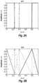
- the number and location of the knots need to be specified along with the order of the spline.
- the knots sequence be denoted as t 1 ⁇ t 2 ⁇ ⁇ ⁇ t n , where n is the number of knots.
- the B-spline basis functions for any order k is generated recursively from the previous order basis functions.
- the knots are non-uniformly spaced at [0,0.25,0.4,0.8,1] and are shown as black dotted lines.
- the matrix P has all the spline coefficients
- the matrix d has all the data
- the matrix A is constructed based on the model structure.
- the spline basis functions have a compact local support and this makes the matrix A to be sparse. Note that bold case letters will be used to represent matrices. Subscripts on matrices will be used to identify rows (first index) and columns (second index) with * denoting all indices. For example, A i * denotes the i th row and A * j denotes the j th column of matrix A .
- the first and second columns of p and d matrices contain the model coefficients and data for x and y respectively. Hence we will also use p * v or d * v with v taking values ⁇ x , y ⁇ to denote the column vectors corresponding to x and y .
- Equation (10) compactly represents the warp model evaluated at the tie point grid where warping data is available either through image registration or some other means. In general, there will be noise in the data either due to measurement process or model mismatch. We would like to adjust the unknown spline coefficient to minimize the mean square error between the model predictions and the data.
- the spline coefficients that minimize the mean square error C is obtained by differentiating Eq.
- This restriction can be easily relaxed by using a different matrix A for the x and y components.
- the warping model matrix A can end up being badly scaled and ill-conditioned leading to a host of numerical issues in the solution of the model spline coefficients.
- the large range of x makes the basis functions for the optical distortion model given by Eq. (6) to have a very large dynamic range if the polynomial model is chosen. With finite precision, the matrices will become rank deficient making it difficult to fit the data correctly. To overcome this problem, it is advisable to first normalize the range of the x and y between 0 and 1. The warping model is then fitted in the normalized domain and the results scaled back to the original domain for subsequent processing.
- an image resampling routine will evaluate the warp using eq. (24) at each pixel location of the reference image to determine the location of the corresponding pixel in the warped band and then use the interpolated pixel value of the warped band at this location to fill in the values for the de-warped band at the reference pixel location.
- the spline and offset coefficients covariance matrices are contained as sub-matrices of ⁇ v .
- ⁇ ⁇ c ⁇ ⁇ ⁇ v n s + 1 : n s + n c , n s + 1 : n s + n c .
- ⁇ fg ( ⁇ ) denotes the slope profile estimated for the warp between bands f and g using image correlation data as given by eq. (21).
- the slope and offset profiles encode the relative motion at the time instances the two bands are measured. In this sense, they are derivatives of the platform motion profile. So the slope and offset profiles should just scale by the ratio of the time difference between the two band pairings.
- the profiles will also be shifted in time between the two band pairings. The shift will be equal to the time difference between the time spacing of the two band pairings.
- N N- 1/2 band pairs in a N band system and we can choose to do image correlation between any of those combinations.
- M the number of band pairs chosen for image correlation.
- P the set of all band pairs on which image correlation is performed.
- ⁇ 13(13) ( ⁇ ) ⁇ 13 ( ⁇ ).
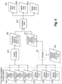
- Fig. 3 shows the data flow during calibration for a 3 band system.
- the 3 sets of band pairs ⁇ 1,2 ⁇ , ⁇ 2,3 ⁇ , and ⁇ 1,3 ⁇ , are correlated 12 to generate warp data 13, 14, 15, respectively. This data will generally be noisy especially in areas where there is little edge information in the image to correlate against.
- the noisy warp data is then fitted using the warp model 16 and the slope, offset, and optical distortion profiles 18, 30, 32, 24, 26, and 28 are generated. This is described above in Sec. 2.
- the optical distortion profiles 24, 26, and 28 between the band pairs are static and stored for future use.
- the slope and offset profiles 18, 30, and 32 should be scaled and shifted versions of one another as seen in eq. (32).
- the time shift is a function of the stick spacing as seen in eq. (33).
- the 3 stick positions 22 ⁇ y 1 , y 2 , y 3 ⁇ can be estimated 20. Note that we can only solve for the relative spacing between the sticks so y 1 can be set to zero without loss of generality and the other stick positions ⁇ y 2 , y 3 ⁇ can be solved for in a least squares sense from the 3 time shift measurements.
- Fig. 4 shows the on-line data flow for computing the warps between all pairs of a 3 band system using data from just a single image correlation. This configuration would be used if computational speed is very important and reduced accuracy can be tolerated. Note that the process for Fig. 4 is run every time a new image is acquired (on-line) whereas the process for Fig. 3 need run only once (off-line) on a previously collected image data set to estimate the calibration parameters subsequently used in the on-line process. In this case, band pair ⁇ 1,2 ⁇ of the acquired image is fed to the image correlation routine 120 to generate the noisy warp data 140. The warp model 160 is fitted to this data to generate the slope, offset, and optical distortion profiles 180 and 240. The profiles can then be used in eq.
- Equation (32) is used to do the prediction.
- the predicted slope and offset profiles 36 along with the calibrated optical distortion profiles 38, i.e. calibrated optical distortions 26 and 28 from Fig. 3 are then used to compute 40, using eq. (24), the warps 46 and 48 for band pairs ⁇ 2,3 ⁇ and ⁇ 1,3 ⁇ , respectively, at any location.
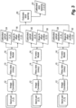
- Fig. 5 shows the data flow for computing the warps 44, 46, and 48 between all pairs of a 3 band system by leveraging all available information.
- the image correlation is done between all band pairs and this data is used to optimally predict the parameters of the warp model. This configuration would be used if accuracy is important and computational speed is of secondary consideration.
- this is an on-line process that is performed every time a new image is acquired.
- the slope, offset, and optical distortion profiles 180, 300, 320, 240, 260, and 280 are first estimated by fitting the warp model 16 to the data generated by the image correlation process 12 for each band pair ( ⁇ 1,2 ⁇ , ⁇ 2,3 ⁇ , and ⁇ 1,3 ⁇ ), of the acquired image.
- the estimation process is the same as shown in Fig. 3 but it is performed on the newly acquired image. All of the 3 slope and offset profiles 180, 300, and 320 are used to predict 340 slope and offset profile for each band pair using eq. (32). This provides 3 predictions for each band pair, which are optimally combined using eq. (36) to produce a single smoothed estimate 360 of the slope and offset.
- the optical distortion profiles 240, 260, and 280 for each band pair may also optionally be smoothed 50 using the calibrated optical distortion profile 380 (a collection of calibrated optical distortions 24, 26, and 28 from Fig. 3 ) for each respective band pair.
- the smoothed slope and offset profiles 360 along with the (smoothed) optical distortion profile 52 for each band pair is used to evaluate 400 the warp 440, 460 and 480 for that band pair.
- Fig. 6 shows the data flow for a registration application that uses the generated warps for the example 3 band system.
- band 1 is considered as the reference band and the warped bands 2 and 3 are resampled 54 using the warps between band pairs ⁇ 1,2 ⁇ and ⁇ 1,3 ⁇ respectively.
- the dewarped bands 2 and 3 are now spatially registered to the reference band 1.
- a system for registering images can include a module configured to implement machine readable instructions to perform one or more of the method embodiments described above.
- aspects of the present embodiments may be embodied as a system, method or computer program product. Accordingly, aspects of the present embodiments may take the form of an entirely hardware embodiment, an entirely software embodiment (including firmware, resident software, micro-code, etc.) or an embodiment combining software and hardware aspects that may all generally be referred to herein as a "circuit,” “module” or “system.” Furthermore, aspects of the present disclosure may take the form of a computer program product embodied in one or more computer readable medium(s) having computer readable program code embodied thereon.
- the computer readable medium may be a computer readable signal medium or a computer readable storage medium.
- a computer readable storage medium may be, for example, but not limited to, an electronic, magnetic, optical, electromagnetic, infrared, or semiconductor system, apparatus, or device, or any suitable combination of the foregoing.
- a computer readable storage medium may be any tangible medium that can contain, or store a program for use by or in connection with an instruction execution system, apparatus, or device.
- a computer readable signal medium may include a propagated data signal with computer readable program code embodied therein, for example, in baseband or as part of a carrier wave. Such a propagated signal may take any of a variety of forms, including, but not limited to, electro-magnetic, optical, or any suitable combination thereof.
- a computer readable signal medium may be any computer readable medium that is not a computer readable storage medium and that can communicate, propagate, or transport a program for use by or in connection with an instruction execution system, apparatus, or device.
- Program code embodied on a computer readable medium may be transmitted using any appropriate medium, including but not limited to wireless, wireline, optical fiber cable, RF, etc., or any suitable combination of the foregoing.
- Computer program code for carrying out operations for aspects of the present disclosure may be written in any combination of one or more programming languages, including an object oriented programming language such as Java, Smalltalk, C++ or the like and conventional procedural programming languages, such as the "C" programming language or similar programming languages.
- the program code may execute entirely on the user's computer, partly on the user's computer, as a stand-alone software package, partly on the user's computer and partly on a remote computer or entirely on the remote computer or server.
- the remote computer may be connected to the user's computer through any type of network, including a local area network (LAN) or a wide area network (WAN), or the connection may be made to an external computer (for example, through the Internet using an Internet Service Provider).
- LAN local area network
- WAN wide area network
- Internet Service Provider for example, AT&T, MCI, Sprint, EarthLink, MSN, GTE, etc.
- These computer program instructions may also be stored in a computer readable medium that can direct a computer, other programmable data processing apparatus, or other devices to function in a particular manner, such that the instructions stored in the computer readable medium produce an article of manufacture including instructions which implement the function/act specified in the flowchart and/or block diagram block or blocks.
- the computer program instructions may also be loaded onto a computer, other programmable data processing apparatus, or other devices to cause a series of operational steps to be performed on the computer, other programmable apparatus or other devices to produce a computer implemented process such that the instructions which execute on the computer or other programmable apparatus provide processes for implementing the functions/acts specified in a flowchart and/or block diagram block or blocks
Landscapes
- Engineering & Computer Science (AREA)
- Physics & Mathematics (AREA)
- General Physics & Mathematics (AREA)
- Theoretical Computer Science (AREA)
- Computer Vision & Pattern Recognition (AREA)
- Image Processing (AREA)
- Image Analysis (AREA)
Claims (5)
- Procédé mis en œuvre par ordinateur pour prédire les déformations pour l'enregistrement d'images entre des paires de bandes dans un système à N bandes, dans lequel un réseau à plan focal, FPA, est utilisé pour acquérir l'imagerie, et dans lequel le FPA comprend des réseaux de capteurs linéaires, des bâtons, dans lequel les bâtons sont positionnés le long d'une direction y et sont déplacés les uns par rapport aux autres spatialement dans la direction y, et dans lequel les bâtons sont montés sur une plate-forme se déplaçant dans la direction y, le procédé comprenant :la réception de données de déformation (13 ; 14 ; 15 ; 140) pour une première paire de bandes dans un système à N bandes ;l'ajustement d'un modèle de déformation (16 ; 160) aux données de déformation (13 ; 14 ; 15 ; 140) pour produire un profil de décalage pour la première paire de bandes, dans lequel le modèle de déformation (16 ; 160) a une pente et un décalage pour un une translation variable dans l'espace entre une paire de bandes, et le profil de décalage est le décalage en fonction de y pour la translation variable dans l'espace entre la paire de bandes ;la prédiction d'un profil de décalage respectif pour au moins une autre paire de bandes dans le système à N bandes ;l'utilisation du profil de décalage respectif prédit pour générer une déformation (44 ; 46 ; 48 ; 440 ; 460 ; 480) pour l'au moins une autre paire de bandes ; etl'enregistrement d'images de l'au moins une autre paire de bandes à l'aide de la déformation pour l'au moins une autre paire de bandes ;le procédé caractérisé en ce que la prédiction d'un profil de décalage respectif inclut :l'estimation de l'espacement des bâtons (22) pour les N bandes du FPA ; etle décalage et la mise à l'échelle du profil de décalage pour la première paire de bandes, dans lequel les valeurs de décalage et de mise à l'échelle du profil de décalage pour la première paire de bandes sont dérivées de l'espacement des bâtons (22) des bandes dans la première paire de bandes et des bandes dans au moins une autre paire de bandes.
- Procédé selon la revendication 1, dans lequel l'ajustement d'un modèle de déformation (16 ; 160) aux données de déformation (13 ; 14 ; 15 ; 140) inclut la production d'un profil de pente pour la première paire de bandes, le profil de pente étant la pente en fonction de y pour la translation variable dans l'espace entre une paire de bandes, et dans lequel le procédé inclut la prédiction d'un profil de pente respectif pour au moins une autre paire de bandes dans le système à N bandes, et dans lequel l'utilisation du profil de décalage prédit pour générer une déformation inclut l'utilisation à la fois des profils de décalage et de pente prévus pour générer la déformation.
- Procédé selon la revendication 1 ou 2, dans lequel les valeurs de décalage et de mise à l'échelle pour prédire l'au moins une autre paire de bandes, d et e, à partir de la première paire de bandes, f et g, sont données comme
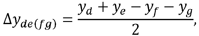

- Procédé selon la revendication 3, dans lequel la prédiction d'un profil de décalage respectif pour au moins une autre paire de bandes, d et e, inclut le décalage et la mise à l'échelle du profil de décalage pour la première paire de bandes, f et g

- Procédé selon une quelconque revendication précédente, dans lequel l'utilisation du profil de décalage respectif prédit pour générer une déformation pour l'au moins une autre paire de bandes inclut l'utilisation d'un profil de distorsion optique respectif (24 ; 26 ; 28 ; 240 ; 260 ; 280) pour chaque paire de bandes respective.
Applications Claiming Priority (1)
| Application Number | Priority Date | Filing Date | Title |
|---|---|---|---|
| US201662321008P | 2016-04-11 | 2016-04-11 |
Publications (3)
| Publication Number | Publication Date |
|---|---|
| EP3232403A2 EP3232403A2 (fr) | 2017-10-18 |
| EP3232403A3 EP3232403A3 (fr) | 2017-11-29 |
| EP3232403B1 true EP3232403B1 (fr) | 2024-05-29 |
Family
ID=58464172
Family Applications (1)
| Application Number | Title | Priority Date | Filing Date |
|---|---|---|---|
| EP17162276.4A Active EP3232403B1 (fr) | 2016-04-11 | 2017-03-22 | Enregistrement d'image multispectrale rapide par modélisation de mouvement de la plate-forme |
Country Status (2)
| Country | Link |
|---|---|
| US (2) | US10360688B2 (fr) |
| EP (1) | EP3232403B1 (fr) |
Families Citing this family (7)
| Publication number | Priority date | Publication date | Assignee | Title |
|---|---|---|---|---|
| CN109598745B (zh) * | 2018-12-25 | 2021-08-17 | 上海联影智能医疗科技有限公司 | 图像配准方法、装置和计算机设备 |
| CN110009670A (zh) * | 2019-03-28 | 2019-07-12 | 上海交通大学 | 基于fast特征提取和piifd特征描述的异源图像配准方法 |
| US11601135B2 (en) * | 2020-02-27 | 2023-03-07 | BTS Software Solutions, LLC | Internet of things data compression system and method |
| US12395313B1 (en) * | 2020-08-28 | 2025-08-19 | Response Images, LLC | Methods and sensor array platforms for creating and monitoring cryptographic blockchain images and executing programs based on monitored images |
| EP4053794A1 (fr) * | 2021-03-05 | 2022-09-07 | Leica Microsystems CMS GmbH | Système de microscope multispectral et procédé d'enregistrement d'une première image et d'une seconde image au moyen de ce système |
| CN116309750B (zh) * | 2023-03-20 | 2026-04-14 | 四川省星时代智能卫星科技有限公司 | 微纳卫星的光学遥感数据配准方法、存储介质及电子设备 |
| US20240412390A1 (en) * | 2023-06-08 | 2024-12-12 | Mediatek Inc. | Method and electronic system for image alignment |
Family Cites Families (19)
| Publication number | Priority date | Publication date | Assignee | Title |
|---|---|---|---|---|
| JP3935507B2 (ja) * | 1996-02-28 | 2007-06-27 | 松下電器産業株式会社 | 高解像度および立体映像記録用光ディスク、光ディスク再生装置、光ディスク記録装置 |
| JP2002527953A (ja) * | 1998-10-02 | 2002-08-27 | マクロニクス インターナショナル カンパニー リミテッド | キーストーン歪みを防止する方法および装置 |
| GB2372656A (en) * | 2001-02-23 | 2002-08-28 | Ind Control Systems Ltd | Optical position determination |
| US6503201B1 (en) * | 2001-10-03 | 2003-01-07 | Koninklijke Philips Electronics N.V. | Correction of extended field of view images for distortion due to scanhead motion |
| US7043474B2 (en) * | 2002-04-15 | 2006-05-09 | International Business Machines Corporation | System and method for measuring image similarity based on semantic meaning |
| US7643684B2 (en) * | 2003-07-15 | 2010-01-05 | Samsung Electronics Co., Ltd. | Apparatus for and method of constructing multi-view face database, and apparatus for and method of generating multi-view face descriptor |
| US7162063B1 (en) * | 2003-07-29 | 2007-01-09 | Western Research Company, Inc. | Digital skin lesion imaging system and method |
| US7719563B2 (en) * | 2003-12-11 | 2010-05-18 | Angus Richards | VTV system |
| US7751651B2 (en) | 2004-04-02 | 2010-07-06 | The Boeing Company | Processing architecture for automatic image registration |
| US8446468B1 (en) | 2007-06-19 | 2013-05-21 | University Of Southern California | Moving object detection using a mobile infrared camera |
| US8463078B2 (en) * | 2007-08-23 | 2013-06-11 | Lockheed Martin Corporation | Multi-bank TDI approach for high-sensitivity scanners |
| US8390628B2 (en) * | 2007-09-11 | 2013-03-05 | Sony Computer Entertainment America Llc | Facial animation using motion capture data |
| US8194952B2 (en) * | 2008-06-04 | 2012-06-05 | Raytheon Company | Image processing system and methods for aligning skin features for early skin cancer detection systems |
| US8219438B1 (en) * | 2008-06-30 | 2012-07-10 | Videomining Corporation | Method and system for measuring shopper response to products based on behavior and facial expression |
| WO2010028811A1 (fr) * | 2008-09-10 | 2010-03-18 | Nobel Biocare Services Ag | Dispositif et procédure d'implantation d'implant dentaire |
| US8503037B2 (en) * | 2009-06-09 | 2013-08-06 | Xerox Corporation | Reducing IOP registration error in a digital document system |
| US20110164108A1 (en) | 2009-12-30 | 2011-07-07 | Fivefocal Llc | System With Selective Narrow FOV and 360 Degree FOV, And Associated Methods |
| ITTO20111145A1 (it) * | 2011-12-13 | 2013-06-14 | Sidel Spa Con Socio Unico | Dispositivo convogliatore per articoli ed impianto di trattamento di tali articoli comprendente il suddetto dispositivo convogliatore |
| US9007490B1 (en) * | 2013-03-14 | 2015-04-14 | Amazon Technologies, Inc. | Approaches for creating high quality images |
-
2017
- 2017-03-22 EP EP17162276.4A patent/EP3232403B1/fr active Active
- 2017-04-07 US US15/482,212 patent/US10360688B2/en active Active
-
2018
- 2018-12-05 US US16/210,091 patent/US10769801B2/en active Active
Also Published As
| Publication number | Publication date |
|---|---|
| US10360688B2 (en) | 2019-07-23 |
| EP3232403A3 (fr) | 2017-11-29 |
| EP3232403A2 (fr) | 2017-10-18 |
| US10769801B2 (en) | 2020-09-08 |
| US20190114791A1 (en) | 2019-04-18 |
| US20170294024A1 (en) | 2017-10-12 |
Similar Documents
| Publication | Publication Date | Title |
|---|---|---|
| EP3232403B1 (fr) | Enregistrement d'image multispectrale rapide par modélisation de mouvement de la plate-forme | |
| Liu et al. | A new polarization image demosaicking algorithm by exploiting inter-channel correlations with guided filtering | |
| Wang et al. | TPSSI-Net: Fast and enhanced two-path iterative network for 3D SAR sparse imaging | |
| Güven et al. | An augmented Lagrangian method for complex-valued compressed SAR imaging | |
| US8351740B2 (en) | Correlatability analysis for sparse alignment | |
| US8078009B2 (en) | Optical flow registration of panchromatic/multi-spectral image pairs | |
| CN110688763B (zh) | 一种基于脉冲型ToF相机深度和光强图像的多径效应补偿方法 | |
| US10762654B2 (en) | Method and system for three-dimensional model reconstruction | |
| CN121073780B (zh) | 一种基于巨型遥感星群的时空谱联合超分辨率重建方法 | |
| EP3229207B1 (fr) | Modèles de chaîne pour l'enregistrement d'imagerie multispectrale | |
| Sentlinger et al. | Sub-pixel water temperature estimation from thermal-infrared imagery using vectorized lake features | |
| CN106646470A (zh) | 基于广义正交匹配追踪的层析sar三维点云生成方法 | |
| Fouhey et al. | Large-scale Spatial Cross-calibration of Hinode/SOT-SP and SDO/HMI | |
| Aiazzi et al. | Deployment of pansharpening for correction of local misalignments between MS and Pan | |
| Lylko et al. | Prototype of satellite infrared spectroradiometer with superresolution | |
| Montagnon et al. | A new deep-learning approach for the sub-pixel registration of satellite images containing sharp displacement discontinuities | |
| Conran et al. | A new technique to define the spatial resolution of imaging sensors | |
| Galbraith et al. | Resampling methods for the MTI coregistration product | |
| Saquib et al. | Spline warp model for registering pushbroom multispectral imagery | |
| Cain | Bayesian-based subpixel brightness temperature estimation from multichannel infrared GOES radiometer data | |
| Murtada et al. | Accelerated consensus ADMM for widely distributed radar imaging | |
| Mejia et al. | Filtered gradient reconstruction algorithm for compressive spectral imaging | |
| Chen et al. | Surface velocities from multiple-tracer image sequences | |
| Grycewicz et al. | Avoiding stair-step artifacts in image registration for GOES-R navigation and registration assessment | |
| Stelter et al. | Atmospheric correction using diffusion models and MODTRAN for constrained training |
Legal Events
| Date | Code | Title | Description |
|---|---|---|---|
| PUAI | Public reference made under article 153(3) epc to a published international application that has entered the european phase |
Free format text: ORIGINAL CODE: 0009012 |
|
| STAA | Information on the status of an ep patent application or granted ep patent |
Free format text: STATUS: THE APPLICATION HAS BEEN PUBLISHED |
|
| AK | Designated contracting states |
Kind code of ref document: A2 Designated state(s): AL AT BE BG CH CY CZ DE DK EE ES FI FR GB GR HR HU IE IS IT LI LT LU LV MC MK MT NL NO PL PT RO RS SE SI SK SM TR |
|
| AX | Request for extension of the european patent |
Extension state: BA ME |
|
| PUAL | Search report despatched |
Free format text: ORIGINAL CODE: 0009013 |
|
| AK | Designated contracting states |
Kind code of ref document: A3 Designated state(s): AL AT BE BG CH CY CZ DE DK EE ES FI FR GB GR HR HU IE IS IT LI LT LU LV MC MK MT NL NO PL PT RO RS SE SI SK SM TR |
|
| AX | Request for extension of the european patent |
Extension state: BA ME |
|
| RIC1 | Information provided on ipc code assigned before grant |
Ipc: G06T 7/32 20170101AFI20171025BHEP |
|
| STAA | Information on the status of an ep patent application or granted ep patent |
Free format text: STATUS: REQUEST FOR EXAMINATION WAS MADE |
|
| 17P | Request for examination filed |
Effective date: 20180529 |
|
| RBV | Designated contracting states (corrected) |
Designated state(s): AL AT BE BG CH CY CZ DE DK EE ES FI FR GB GR HR HU IE IS IT LI LT LU LV MC MK MT NL NO PL PT RO RS SE SI SK SM TR |
|
| STAA | Information on the status of an ep patent application or granted ep patent |
Free format text: STATUS: EXAMINATION IS IN PROGRESS |
|
| 17Q | First examination report despatched |
Effective date: 20210211 |
|
| P01 | Opt-out of the competence of the unified patent court (upc) registered |
Effective date: 20230922 |
|
| GRAP | Despatch of communication of intention to grant a patent |
Free format text: ORIGINAL CODE: EPIDOSNIGR1 |
|
| STAA | Information on the status of an ep patent application or granted ep patent |
Free format text: STATUS: GRANT OF PATENT IS INTENDED |
|
| INTG | Intention to grant announced |
Effective date: 20231218 |
|
| GRAS | Grant fee paid |
Free format text: ORIGINAL CODE: EPIDOSNIGR3 |
|
| GRAA | (expected) grant |
Free format text: ORIGINAL CODE: 0009210 |
|
| STAA | Information on the status of an ep patent application or granted ep patent |
Free format text: STATUS: THE PATENT HAS BEEN GRANTED |
|
| AK | Designated contracting states |
Kind code of ref document: B1 Designated state(s): AL AT BE BG CH CY CZ DE DK EE ES FI FR GB GR HR HU IE IS IT LI LT LU LV MC MK MT NL NO PL PT RO RS SE SI SK SM TR |
|
| REG | Reference to a national code |
Ref country code: CH Ref legal event code: EP |
|
| REG | Reference to a national code |
Ref country code: IE Ref legal event code: FG4D |
|
| REG | Reference to a national code |
Ref country code: DE Ref legal event code: R096 Ref document number: 602017082238 Country of ref document: DE |
|
| REG | Reference to a national code |
Ref country code: LT Ref legal event code: MG9D |
|
| REG | Reference to a national code |
Ref country code: NL Ref legal event code: MP Effective date: 20240529 |
|
| PG25 | Lapsed in a contracting state [announced via postgrant information from national office to epo] |
Ref country code: IS Free format text: LAPSE BECAUSE OF FAILURE TO SUBMIT A TRANSLATION OF THE DESCRIPTION OR TO PAY THE FEE WITHIN THE PRESCRIBED TIME-LIMIT Effective date: 20240929 |
|
| PG25 | Lapsed in a contracting state [announced via postgrant information from national office to epo] |
Ref country code: BG Free format text: LAPSE BECAUSE OF FAILURE TO SUBMIT A TRANSLATION OF THE DESCRIPTION OR TO PAY THE FEE WITHIN THE PRESCRIBED TIME-LIMIT Effective date: 20240529 |
|
| PG25 | Lapsed in a contracting state [announced via postgrant information from national office to epo] |
Ref country code: HR Free format text: LAPSE BECAUSE OF FAILURE TO SUBMIT A TRANSLATION OF THE DESCRIPTION OR TO PAY THE FEE WITHIN THE PRESCRIBED TIME-LIMIT Effective date: 20240529 Ref country code: FI Free format text: LAPSE BECAUSE OF FAILURE TO SUBMIT A TRANSLATION OF THE DESCRIPTION OR TO PAY THE FEE WITHIN THE PRESCRIBED TIME-LIMIT Effective date: 20240529 |
|
| PG25 | Lapsed in a contracting state [announced via postgrant information from national office to epo] |
Ref country code: GR Free format text: LAPSE BECAUSE OF FAILURE TO SUBMIT A TRANSLATION OF THE DESCRIPTION OR TO PAY THE FEE WITHIN THE PRESCRIBED TIME-LIMIT Effective date: 20240830 |
|
| REG | Reference to a national code |
Ref country code: AT Ref legal event code: MK05 Ref document number: 1691278 Country of ref document: AT Kind code of ref document: T Effective date: 20240529 |
|
| PG25 | Lapsed in a contracting state [announced via postgrant information from national office to epo] |
Ref country code: ES Free format text: LAPSE BECAUSE OF FAILURE TO SUBMIT A TRANSLATION OF THE DESCRIPTION OR TO PAY THE FEE WITHIN THE PRESCRIBED TIME-LIMIT Effective date: 20240529 |
|
| PG25 | Lapsed in a contracting state [announced via postgrant information from national office to epo] |
Ref country code: AT Free format text: LAPSE BECAUSE OF FAILURE TO SUBMIT A TRANSLATION OF THE DESCRIPTION OR TO PAY THE FEE WITHIN THE PRESCRIBED TIME-LIMIT Effective date: 20240529 |
|
| PG25 | Lapsed in a contracting state [announced via postgrant information from national office to epo] |
Ref country code: PL Free format text: LAPSE BECAUSE OF FAILURE TO SUBMIT A TRANSLATION OF THE DESCRIPTION OR TO PAY THE FEE WITHIN THE PRESCRIBED TIME-LIMIT Effective date: 20240529 |
|
| PG25 | Lapsed in a contracting state [announced via postgrant information from national office to epo] |
Ref country code: LV Free format text: LAPSE BECAUSE OF FAILURE TO SUBMIT A TRANSLATION OF THE DESCRIPTION OR TO PAY THE FEE WITHIN THE PRESCRIBED TIME-LIMIT Effective date: 20240529 |
|
| PG25 | Lapsed in a contracting state [announced via postgrant information from national office to epo] |
Ref country code: PL Free format text: LAPSE BECAUSE OF FAILURE TO SUBMIT A TRANSLATION OF THE DESCRIPTION OR TO PAY THE FEE WITHIN THE PRESCRIBED TIME-LIMIT Effective date: 20240529 Ref country code: NO Free format text: LAPSE BECAUSE OF FAILURE TO SUBMIT A TRANSLATION OF THE DESCRIPTION OR TO PAY THE FEE WITHIN THE PRESCRIBED TIME-LIMIT Effective date: 20240829 Ref country code: LV Free format text: LAPSE BECAUSE OF FAILURE TO SUBMIT A TRANSLATION OF THE DESCRIPTION OR TO PAY THE FEE WITHIN THE PRESCRIBED TIME-LIMIT Effective date: 20240529 Ref country code: IS Free format text: LAPSE BECAUSE OF FAILURE TO SUBMIT A TRANSLATION OF THE DESCRIPTION OR TO PAY THE FEE WITHIN THE PRESCRIBED TIME-LIMIT Effective date: 20240929 Ref country code: HR Free format text: LAPSE BECAUSE OF FAILURE TO SUBMIT A TRANSLATION OF THE DESCRIPTION OR TO PAY THE FEE WITHIN THE PRESCRIBED TIME-LIMIT Effective date: 20240529 Ref country code: GR Free format text: LAPSE BECAUSE OF FAILURE TO SUBMIT A TRANSLATION OF THE DESCRIPTION OR TO PAY THE FEE WITHIN THE PRESCRIBED TIME-LIMIT Effective date: 20240830 Ref country code: FI Free format text: LAPSE BECAUSE OF FAILURE TO SUBMIT A TRANSLATION OF THE DESCRIPTION OR TO PAY THE FEE WITHIN THE PRESCRIBED TIME-LIMIT Effective date: 20240529 Ref country code: ES Free format text: LAPSE BECAUSE OF FAILURE TO SUBMIT A TRANSLATION OF THE DESCRIPTION OR TO PAY THE FEE WITHIN THE PRESCRIBED TIME-LIMIT Effective date: 20240529 Ref country code: BG Free format text: LAPSE BECAUSE OF FAILURE TO SUBMIT A TRANSLATION OF THE DESCRIPTION OR TO PAY THE FEE WITHIN THE PRESCRIBED TIME-LIMIT Effective date: 20240529 Ref country code: AT Free format text: LAPSE BECAUSE OF FAILURE TO SUBMIT A TRANSLATION OF THE DESCRIPTION OR TO PAY THE FEE WITHIN THE PRESCRIBED TIME-LIMIT Effective date: 20240529 Ref country code: RS Free format text: LAPSE BECAUSE OF FAILURE TO SUBMIT A TRANSLATION OF THE DESCRIPTION OR TO PAY THE FEE WITHIN THE PRESCRIBED TIME-LIMIT Effective date: 20240829 |
|
| PG25 | Lapsed in a contracting state [announced via postgrant information from national office to epo] |
Ref country code: NL Free format text: LAPSE BECAUSE OF FAILURE TO SUBMIT A TRANSLATION OF THE DESCRIPTION OR TO PAY THE FEE WITHIN THE PRESCRIBED TIME-LIMIT Effective date: 20240529 |
|
| PG25 | Lapsed in a contracting state [announced via postgrant information from national office to epo] |
Ref country code: NL Free format text: LAPSE BECAUSE OF FAILURE TO SUBMIT A TRANSLATION OF THE DESCRIPTION OR TO PAY THE FEE WITHIN THE PRESCRIBED TIME-LIMIT Effective date: 20240529 |
|
| PG25 | Lapsed in a contracting state [announced via postgrant information from national office to epo] |
Ref country code: DK Free format text: LAPSE BECAUSE OF FAILURE TO SUBMIT A TRANSLATION OF THE DESCRIPTION OR TO PAY THE FEE WITHIN THE PRESCRIBED TIME-LIMIT Effective date: 20240529 |
|
| PG25 | Lapsed in a contracting state [announced via postgrant information from national office to epo] |
Ref country code: EE Free format text: LAPSE BECAUSE OF FAILURE TO SUBMIT A TRANSLATION OF THE DESCRIPTION OR TO PAY THE FEE WITHIN THE PRESCRIBED TIME-LIMIT Effective date: 20240529 |
|
| PG25 | Lapsed in a contracting state [announced via postgrant information from national office to epo] |
Ref country code: CZ Free format text: LAPSE BECAUSE OF FAILURE TO SUBMIT A TRANSLATION OF THE DESCRIPTION OR TO PAY THE FEE WITHIN THE PRESCRIBED TIME-LIMIT Effective date: 20240529 |
|
| PG25 | Lapsed in a contracting state [announced via postgrant information from national office to epo] |
Ref country code: RO Free format text: LAPSE BECAUSE OF FAILURE TO SUBMIT A TRANSLATION OF THE DESCRIPTION OR TO PAY THE FEE WITHIN THE PRESCRIBED TIME-LIMIT Effective date: 20240529 Ref country code: SK Free format text: LAPSE BECAUSE OF FAILURE TO SUBMIT A TRANSLATION OF THE DESCRIPTION OR TO PAY THE FEE WITHIN THE PRESCRIBED TIME-LIMIT Effective date: 20240529 |
|
| PG25 | Lapsed in a contracting state [announced via postgrant information from national office to epo] |
Ref country code: SM Free format text: LAPSE BECAUSE OF FAILURE TO SUBMIT A TRANSLATION OF THE DESCRIPTION OR TO PAY THE FEE WITHIN THE PRESCRIBED TIME-LIMIT Effective date: 20240529 |
|
| PG25 | Lapsed in a contracting state [announced via postgrant information from national office to epo] |
Ref country code: SM Free format text: LAPSE BECAUSE OF FAILURE TO SUBMIT A TRANSLATION OF THE DESCRIPTION OR TO PAY THE FEE WITHIN THE PRESCRIBED TIME-LIMIT Effective date: 20240529 Ref country code: SK Free format text: LAPSE BECAUSE OF FAILURE TO SUBMIT A TRANSLATION OF THE DESCRIPTION OR TO PAY THE FEE WITHIN THE PRESCRIBED TIME-LIMIT Effective date: 20240529 Ref country code: RO Free format text: LAPSE BECAUSE OF FAILURE TO SUBMIT A TRANSLATION OF THE DESCRIPTION OR TO PAY THE FEE WITHIN THE PRESCRIBED TIME-LIMIT Effective date: 20240529 Ref country code: EE Free format text: LAPSE BECAUSE OF FAILURE TO SUBMIT A TRANSLATION OF THE DESCRIPTION OR TO PAY THE FEE WITHIN THE PRESCRIBED TIME-LIMIT Effective date: 20240529 Ref country code: DK Free format text: LAPSE BECAUSE OF FAILURE TO SUBMIT A TRANSLATION OF THE DESCRIPTION OR TO PAY THE FEE WITHIN THE PRESCRIBED TIME-LIMIT Effective date: 20240529 Ref country code: CZ Free format text: LAPSE BECAUSE OF FAILURE TO SUBMIT A TRANSLATION OF THE DESCRIPTION OR TO PAY THE FEE WITHIN THE PRESCRIBED TIME-LIMIT Effective date: 20240529 |
|
| PG25 | Lapsed in a contracting state [announced via postgrant information from national office to epo] |
Ref country code: IT Free format text: LAPSE BECAUSE OF FAILURE TO SUBMIT A TRANSLATION OF THE DESCRIPTION OR TO PAY THE FEE WITHIN THE PRESCRIBED TIME-LIMIT Effective date: 20240529 |
|
| REG | Reference to a national code |
Ref country code: DE Ref legal event code: R097 Ref document number: 602017082238 Country of ref document: DE |
|
| PLBE | No opposition filed within time limit |
Free format text: ORIGINAL CODE: 0009261 |
|
| STAA | Information on the status of an ep patent application or granted ep patent |
Free format text: STATUS: NO OPPOSITION FILED WITHIN TIME LIMIT |
|
| PG25 | Lapsed in a contracting state [announced via postgrant information from national office to epo] |
Ref country code: SI Free format text: LAPSE BECAUSE OF FAILURE TO SUBMIT A TRANSLATION OF THE DESCRIPTION OR TO PAY THE FEE WITHIN THE PRESCRIBED TIME-LIMIT Effective date: 20240529 |
|
| 26N | No opposition filed |
Effective date: 20250303 |
|
| PG25 | Lapsed in a contracting state [announced via postgrant information from national office to epo] |
Ref country code: SE Free format text: LAPSE BECAUSE OF FAILURE TO SUBMIT A TRANSLATION OF THE DESCRIPTION OR TO PAY THE FEE WITHIN THE PRESCRIBED TIME-LIMIT Effective date: 20240529 |
|
| PG25 | Lapsed in a contracting state [announced via postgrant information from national office to epo] |
Ref country code: MC Free format text: LAPSE BECAUSE OF FAILURE TO SUBMIT A TRANSLATION OF THE DESCRIPTION OR TO PAY THE FEE WITHIN THE PRESCRIBED TIME-LIMIT Effective date: 20240529 |
|
| REG | Reference to a national code |
Ref country code: CH Ref legal event code: H13 Free format text: ST27 STATUS EVENT CODE: U-0-0-H10-H13 (AS PROVIDED BY THE NATIONAL OFFICE) Effective date: 20251023 |
|
| PG25 | Lapsed in a contracting state [announced via postgrant information from national office to epo] |
Ref country code: LU Free format text: LAPSE BECAUSE OF NON-PAYMENT OF DUE FEES Effective date: 20250322 |
|
| REG | Reference to a national code |
Ref country code: BE Ref legal event code: MM Effective date: 20250331 |
|
| PG25 | Lapsed in a contracting state [announced via postgrant information from national office to epo] |
Ref country code: BE Free format text: LAPSE BECAUSE OF NON-PAYMENT OF DUE FEES Effective date: 20250331 |
|
| PG25 | Lapsed in a contracting state [announced via postgrant information from national office to epo] |
Ref country code: CH Free format text: LAPSE BECAUSE OF NON-PAYMENT OF DUE FEES Effective date: 20250331 |
|
| PG25 | Lapsed in a contracting state [announced via postgrant information from national office to epo] |
Ref country code: IE Free format text: LAPSE BECAUSE OF NON-PAYMENT OF DUE FEES Effective date: 20250322 |
|
| PGFP | Annual fee paid to national office [announced via postgrant information from national office to epo] |
Ref country code: GB Payment date: 20260220 Year of fee payment: 10 |
|
| PGFP | Annual fee paid to national office [announced via postgrant information from national office to epo] |
Ref country code: DE Payment date: 20260219 Year of fee payment: 10 |
|
| PGFP | Annual fee paid to national office [announced via postgrant information from national office to epo] |
Ref country code: FR Payment date: 20260219 Year of fee payment: 10 |