EP3232496A1 - Électrode - Google Patents
Électrode Download PDFInfo
- Publication number
- EP3232496A1 EP3232496A1 EP15867779.9A EP15867779A EP3232496A1 EP 3232496 A1 EP3232496 A1 EP 3232496A1 EP 15867779 A EP15867779 A EP 15867779A EP 3232496 A1 EP3232496 A1 EP 3232496A1
- Authority
- EP
- European Patent Office
- Prior art keywords
- terminal
- electrode
- ptc element
- rechargeable battery
- electrode according
- Prior art date
- Legal status (The legal status is an assumption and is not a legal conclusion. Google has not performed a legal analysis and makes no representation as to the accuracy of the status listed.)
- Withdrawn
Links
Images

Classifications
-
- H—ELECTRICITY
- H01—ELECTRIC ELEMENTS
- H01M—PROCESSES OR MEANS, e.g. BATTERIES, FOR THE DIRECT CONVERSION OF CHEMICAL ENERGY INTO ELECTRICAL ENERGY
- H01M50/00—Constructional details or processes of manufacture of the non-active parts of electrochemical cells other than fuel cells, e.g. hybrid cells
- H01M50/50—Current conducting connections for cells or batteries
- H01M50/572—Means for preventing undesired use or discharge
- H01M50/574—Devices or arrangements for the interruption of current
- H01M50/581—Devices or arrangements for the interruption of current in response to temperature
-
- H—ELECTRICITY
- H01—ELECTRIC ELEMENTS
- H01C—RESISTORS
- H01C1/00—Details
- H01C1/14—Terminals or tapping points specially adapted for resistors; Arrangements of terminals or tapping points on resistors
-
- H—ELECTRICITY
- H01—ELECTRIC ELEMENTS
- H01C—RESISTORS
- H01C1/00—Details
- H01C1/14—Terminals or tapping points specially adapted for resistors; Arrangements of terminals or tapping points on resistors
- H01C1/1406—Terminals or electrodes formed on resistive elements having positive temperature coefficient
-
- H—ELECTRICITY
- H01—ELECTRIC ELEMENTS
- H01C—RESISTORS
- H01C1/00—Details
- H01C1/14—Terminals or tapping points specially adapted for resistors; Arrangements of terminals or tapping points on resistors
- H01C1/144—Terminals or tapping points specially adapted for resistors; Arrangements of terminals or tapping points on resistors the terminals or tapping points being welded or soldered
-
- H—ELECTRICITY
- H01—ELECTRIC ELEMENTS
- H01C—RESISTORS
- H01C7/00—Non-adjustable resistors formed as one or more layers or coatings; Non-adjustable resistors made from powdered conducting material or powdered semi-conducting material with or without insulating material
- H01C7/02—Non-adjustable resistors formed as one or more layers or coatings; Non-adjustable resistors made from powdered conducting material or powdered semi-conducting material with or without insulating material having positive temperature coefficient
-
- H—ELECTRICITY
- H01—ELECTRIC ELEMENTS
- H01G—CAPACITORS; CAPACITORS, RECTIFIERS, DETECTORS, SWITCHING DEVICES, LIGHT-SENSITIVE OR TEMPERATURE-SENSITIVE DEVICES OF THE ELECTROLYTIC TYPE
- H01G11/00—Hybrid capacitors, i.e. capacitors having different positive and negative electrodes; Electric double-layer [EDL] capacitors; Processes for the manufacture thereof or of parts thereof
- H01G11/04—Hybrid capacitors
- H01G11/06—Hybrid capacitors with one of the electrodes allowing ions to be reversibly doped thereinto, e.g. lithium ion capacitors [LIC]
-
- H—ELECTRICITY
- H01—ELECTRIC ELEMENTS
- H01G—CAPACITORS; CAPACITORS, RECTIFIERS, DETECTORS, SWITCHING DEVICES, LIGHT-SENSITIVE OR TEMPERATURE-SENSITIVE DEVICES OF THE ELECTROLYTIC TYPE
- H01G11/00—Hybrid capacitors, i.e. capacitors having different positive and negative electrodes; Electric double-layer [EDL] capacitors; Processes for the manufacture thereof or of parts thereof
- H01G11/14—Arrangements or processes for adjusting or protecting hybrid or EDL capacitors
- H01G11/16—Arrangements or processes for adjusting or protecting hybrid or EDL capacitors against electric overloads, e.g. including fuses
-
- H—ELECTRICITY
- H01—ELECTRIC ELEMENTS
- H01G—CAPACITORS; CAPACITORS, RECTIFIERS, DETECTORS, SWITCHING DEVICES, LIGHT-SENSITIVE OR TEMPERATURE-SENSITIVE DEVICES OF THE ELECTROLYTIC TYPE
- H01G11/00—Hybrid capacitors, i.e. capacitors having different positive and negative electrodes; Electric double-layer [EDL] capacitors; Processes for the manufacture thereof or of parts thereof
- H01G11/74—Terminals, e.g. extensions of current collectors
-
- H—ELECTRICITY
- H01—ELECTRIC ELEMENTS
- H01M—PROCESSES OR MEANS, e.g. BATTERIES, FOR THE DIRECT CONVERSION OF CHEMICAL ENERGY INTO ELECTRICAL ENERGY
- H01M10/00—Secondary cells; Manufacture thereof
- H01M10/05—Accumulators with non-aqueous electrolyte
- H01M10/052—Li-accumulators
- H01M10/0525—Rocking-chair batteries, i.e. batteries with lithium insertion or intercalation in both electrodes; Lithium-ion batteries
-
- H—ELECTRICITY
- H01—ELECTRIC ELEMENTS
- H01M—PROCESSES OR MEANS, e.g. BATTERIES, FOR THE DIRECT CONVERSION OF CHEMICAL ENERGY INTO ELECTRICAL ENERGY
- H01M10/00—Secondary cells; Manufacture thereof
- H01M10/05—Accumulators with non-aqueous electrolyte
- H01M10/056—Accumulators with non-aqueous electrolyte characterised by the materials used as electrolytes, e.g. mixed inorganic/organic electrolytes
- H01M10/0564—Accumulators with non-aqueous electrolyte characterised by the materials used as electrolytes, e.g. mixed inorganic/organic electrolytes the electrolyte being constituted of organic materials only
- H01M10/0565—Polymeric materials, e.g. gel-type or solid-type
-
- H—ELECTRICITY
- H01—ELECTRIC ELEMENTS
- H01M—PROCESSES OR MEANS, e.g. BATTERIES, FOR THE DIRECT CONVERSION OF CHEMICAL ENERGY INTO ELECTRICAL ENERGY
- H01M50/00—Constructional details or processes of manufacture of the non-active parts of electrochemical cells other than fuel cells, e.g. hybrid cells
- H01M50/10—Primary casings; Jackets or wrappings
- H01M50/172—Arrangements of electric connectors penetrating the casing
- H01M50/174—Arrangements of electric connectors penetrating the casing adapted for the shape of the cells
- H01M50/178—Arrangements of electric connectors penetrating the casing adapted for the shape of the cells for pouch or flexible bag cells
-
- H—ELECTRICITY
- H01—ELECTRIC ELEMENTS
- H01M—PROCESSES OR MEANS, e.g. BATTERIES, FOR THE DIRECT CONVERSION OF CHEMICAL ENERGY INTO ELECTRICAL ENERGY
- H01M50/00—Constructional details or processes of manufacture of the non-active parts of electrochemical cells other than fuel cells, e.g. hybrid cells
- H01M50/50—Current conducting connections for cells or batteries
- H01M50/543—Terminals
- H01M50/547—Terminals characterised by the disposition of the terminals on the cells
- H01M50/55—Terminals characterised by the disposition of the terminals on the cells on the same side of the cell
-
- H—ELECTRICITY
- H01—ELECTRIC ELEMENTS
- H01M—PROCESSES OR MEANS, e.g. BATTERIES, FOR THE DIRECT CONVERSION OF CHEMICAL ENERGY INTO ELECTRICAL ENERGY
- H01M50/00—Constructional details or processes of manufacture of the non-active parts of electrochemical cells other than fuel cells, e.g. hybrid cells
- H01M50/50—Current conducting connections for cells or batteries
- H01M50/543—Terminals
- H01M50/552—Terminals characterised by their shape
- H01M50/553—Terminals adapted for prismatic, pouch or rectangular cells
-
- H—ELECTRICITY
- H01—ELECTRIC ELEMENTS
- H01M—PROCESSES OR MEANS, e.g. BATTERIES, FOR THE DIRECT CONVERSION OF CHEMICAL ENERGY INTO ELECTRICAL ENERGY
- H01M50/00—Constructional details or processes of manufacture of the non-active parts of electrochemical cells other than fuel cells, e.g. hybrid cells
- H01M50/50—Current conducting connections for cells or batteries
- H01M50/543—Terminals
- H01M50/562—Terminals characterised by the material
-
- H—ELECTRICITY
- H01—ELECTRIC ELEMENTS
- H01M—PROCESSES OR MEANS, e.g. BATTERIES, FOR THE DIRECT CONVERSION OF CHEMICAL ENERGY INTO ELECTRICAL ENERGY
- H01M2200/00—Safety devices for primary or secondary batteries
- H01M2200/10—Temperature sensitive devices
- H01M2200/106—PTC
-
- H—ELECTRICITY
- H01—ELECTRIC ELEMENTS
- H01M—PROCESSES OR MEANS, e.g. BATTERIES, FOR THE DIRECT CONVERSION OF CHEMICAL ENERGY INTO ELECTRICAL ENERGY
- H01M2220/00—Batteries for particular applications
- H01M2220/30—Batteries in portable systems, e.g. mobile phone, laptop
-
- H—ELECTRICITY
- H01—ELECTRIC ELEMENTS
- H01M—PROCESSES OR MEANS, e.g. BATTERIES, FOR THE DIRECT CONVERSION OF CHEMICAL ENERGY INTO ELECTRICAL ENERGY
- H01M2300/00—Electrolytes
- H01M2300/0017—Non-aqueous electrolytes
- H01M2300/0065—Solid electrolytes
- H01M2300/0082—Organic polymers
-
- Y—GENERAL TAGGING OF NEW TECHNOLOGICAL DEVELOPMENTS; GENERAL TAGGING OF CROSS-SECTIONAL TECHNOLOGIES SPANNING OVER SEVERAL SECTIONS OF THE IPC; TECHNICAL SUBJECTS COVERED BY FORMER USPC CROSS-REFERENCE ART COLLECTIONS [XRACs] AND DIGESTS
- Y02—TECHNOLOGIES OR APPLICATIONS FOR MITIGATION OR ADAPTATION AGAINST CLIMATE CHANGE
- Y02E—REDUCTION OF GREENHOUSE GAS [GHG] EMISSIONS, RELATED TO ENERGY GENERATION, TRANSMISSION OR DISTRIBUTION
- Y02E60/00—Enabling technologies; Technologies with a potential or indirect contribution to GHG emissions mitigation
- Y02E60/10—Energy storage using batteries
Definitions
- the present invention relates to an electrode through which current passes to and from an electronic device, such as an extracting electrode for a rechargeable battery, and to an electronic device using this electrode, such as a rechargeable battery.
- lithium-ion rechargeable batteries are commonly used in electronic devices, especially mobile devices.
- lithium-ion rechargeable batteries use an aluminum or iron canister with sufficient external strength. Therefore, even though lithium-ion rechargeable batteries are light and compact, there are structural limitations on how thin and light these batteries can become because they require external strength. There are also limitations on the shape of lithium-ion rechargeable batteries because a hard exterior material is required.
- lithium-ion polymer rechargeable batteries which do not use a liquid electrolyte are receiving increased attention.
- the electrolyte in a lithium-ion polymer rechargeable batteries is a non-fluid material such as a gel. Because there are no concerns about leaking liquid, the outer coating can be an aluminum laminate film. These are known as pouch-type batteries, and they are extremely light, extremely small, and can assume a wide variety of shapes.
- a protective element is used in the rechargeable battery circuitry.
- the protective element is usually a PTC (positive temperature coefficient) element.
- the PTC element is disposed between the board and an electrode in the lithium-ion polymer rechargeable battery.
- the PTC element is disposed on the board, preferably integrated beforehand with a welding block, and an electrode of the lithium-ion polymer battery is connected on top.
- a PTC element used as a protective element in a rechargeable battery When a PTC element used as a protective element in a rechargeable battery reaches a predetermined temperature, it is activated (tripped) to cut off the flow of current and protect the elements to be protected.
- a rechargeable battery When a rechargeable battery is protected from overheating, the heat from the overheating rechargeable cell is transmitted to the PTC element. The temperature of the PTC element rises, the PTC element is activated, the current is cut off, and the elements to be protected are protected.
- the overcurrent heats up the PTC element. When the element reaches a predetermined temperature, it is activated. The current is cut off and the elements to be protected are protected.
- FIG. 4 shows an example in which a PTC element 38 and a conventional rechargeable battery consisting of a cell 32, positive electrode 34, and negative electrode 36 are connected to a board 40.
- the PTC element 38 is disposed on the board 40 and connected to the negative electrode 36 via a welding tab 42.
- the positive electrode 34 is connected to the board 40 so as to be enveloped by the welding tab 44 in order to facilitate welding to the board.
- Patent Document 1 JP 2014-044865 A
- the present inventors noticed that activation is sometimes delayed when a PTC element is disposed on a board (or near a board) because the board has a large heat capacity and heat transmitted to the PTC element or generated by the PTC element is readily transmitted to the board and dissipated therein. As a result, the temperature of the PTC element is less likely to rise. They also noticed that heat generated by other electronic components on the board (such as by a field-effect transistor or FET) is transmitted to the PTC element via the board, causing the temperature of the PTC element to rise (that is, increase resistance) and possibly lowering the holding current of the PTC element.
- FET field-effect transistor
- a first aspect of the present invention is an electrode for an electrical device, the electrode comprising:
- a second aspect of the present invention is an electrode for an electrical device, the electrode comprising:
- a first terminal and a second terminal are disposed on one or both main surfaces of a PTC element and extend in different directions to create an extracting electrode for a rechargeable cell.
- the PTC element can be arranged closer to the rechargeable cell. Because the PTC element can be arranged closer to the rechargeable battery in the present invention, when the rechargeable cell overheats, the PTC element can detect the heat and become activated more quickly. Because the PTC element is located away from the board, it is less susceptible to heat generated by other electronic components on the board, and the heat from these electronic components can be kept from lowering the holding current of the element.
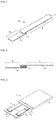
- the extracting electrode 1a in the first embodiment of the present invention has a PTC element 2, a first terminal 4, and a second terminal 6.
- the first terminal 4 and the second terminal 6 are arranged on main surfaces of the PTC element 2 and extend in opposite directions from the PTC element.
- the first terminal 4 is connected electrically to the internal electrode or the current collector in a rechargeable cell, and the second terminal is connected electrically to another electrical component (such as a board). Because the extracting electrode 1 a of the present invention has a PTC element, it also functions as a protecting element.
- the PTC element used in the present invention may be a ceramic PTC element or a polymer PTC element.
- a polymer PTC element is preferred. Compared to a ceramic PTC element, a polymer PTC element is easier to process, has a lower resistance value, and is less likely to self-destruct above a certain temperature.
- Any polymer PTC element common in the art can be used. This element is usually obtained by extruding a conductive composition composed of a conductive filler (carbon black, nickel alloy, etc.) dispersed in a polymer (polyethylene, polyvinylidene fluoride, etc.) and then cutting the extruded product to a predetermined size.
- a conductive filler carbon black, nickel alloy, etc.
- a polymer polyethylene, polyvinylidene fluoride, etc.
- the PTC element may be a PTC element having a thin laminated electrode (foil electrode) on at least one main surface and preferably on both.
- the extracting electrode of the present invention may have a layered metal electrode positioned between the main surface of the PTC element and the first terminal or the second terminal arranged on top.
- the material constituting the layered metal electrode is a conductive metal.
- examples include copper, nickel, aluminum, gold, and alloys thereof.
- a layered metal electrode the PTC composition constituting the PTC element is simultaneously extruded along with the metal sheet (or metal foil) constituting the layered metal electrode. In this way, an extrudate is obtained in which a layer of the PTC composition is interposed between layered metal electrodes.
- a layered metal electrode is obtained by extruding a layer of the PTC composition, interposing the layer between metal sheets (or metal foil), and subjecting the resulting laminate to thermocompression bonding.
- a layer of the PTC composition is plated with conductive metal to obtain layered metal electrodes on both main surfaces of the layer.
- the first terminal 4 is arranged on one main surface of the PTC element 2, and a second terminal 6 is arranged on the other main surface.
- the method used to join the PTC element to the terminals There are no particular restrictions on the method used to join the PTC element to the terminals. Examples include pressure bonding and the use of a conductive adhesive. Other methods include using a PTC element (having a thin metal electrode on both main surfaces of the PTC element) and joining the terminals to the thin metal electrodes on the PTC element using soldering, welding, pressure bonding, or a conductive adhesive. In order to join the components more easily, the terminals can be clad or partially clad, or the joint between the terminals and the PTC component (PTC element) can be plated.
- first terminal 4 and the second terminal 6 There are no particular restrictions on the shape of the first terminal 4 and the second terminal 6 as long as the shape allows them to function as an extracting electrode. Examples include rod shaped and slit shaped terminals. The shape of the first terminal 4 and the second terminal 6 can be the same or different.
- the first terminal 4 and the second terminal 6 each have an extension 8, 10 extending outward on a main surface of the PTC element.
- the extensions 8, 10 of the first terminal 4 and the second terminal 6 extend in opposite directions (directions forming a 180° angle) on the main surfaces of the PTC element.
- the terminals may extend in any direction as long as the first terminal 4 can be connected to a rechargeable cell and the second terminal can be connected to another electronic component.
- the first terminal and the second terminal may be arranged so as to form a 90° angle (right angle).
- the second terminal may extend not in one direction but in two directions or three directions.
- the first terminal 4 and the second terminal 6 are preferably arranged so as to cover the entire main surface and match the shape of the main surface of the PTC element excluding the extension 8.
- the present invention is not restricted to the present aspect.
- Each terminal may also be disposed so as to cover only a portion of the main surface of the PTC element.
- Each terminal may also be arranged so as to overextend slightly from the main surface of the PTC element in any direction.
- the thickness of the first terminal 4 and the second terminal 6 can be, for example, from 0.05 mm to 3.0 mm, preferably from 0.07 to 0.30 mm, and more preferably from 0.10 to 0.15 mm.
- the thickness of the first terminal and the second terminal can be the same or different. Also, the thickness of each terminal does not have to be uniform. It can vary.
- the length of the first terminal can be, for example, from 10 to 200 mm, preferably from 20 to 140 mm, and more preferably from 30 to 80 mm.
- the length of the second terminal can be, for example, from 5 to 100 mm, preferably from 7 to 50 mm, and more preferably from 10 to 30 mm.
- the length of the first terminal 4 and the second terminal 6 can be selected based on the size and type of rechargeable battery using the extracting electrode of the present invention and based on the distance between the PTC element and the rechargeable cell, and the length of the second terminal can be selected based on the size and shape of the other electrical component (such as a board) and based on the distance between the PTC element and the other electrical component.
- the materials constituting the first terminal 4 and the second terminal 6 can be the same or different. There are no particular restrictions on the materials constituting the first terminal 4 and the second terminal 6 as long as the materials are conductive.
- conductive metal materials can be used. Specific examples include nickel, aluminum, stainless steel, iron, copper, tin, titanium, and alloys thereof.
- the first terminal 4 and the second terminal 6 may each be formed from one type of metal or from more than one type of metal.
- the first terminal and the second terminal may have a laminated structure in which layers of two or more types of metal are laminated.
- the first terminal and the second terminal may also have a clad material or may have a plated surface. All or some of each terminal may have a laminated structure. When laminated terminals are used, it is easier to join the terminals to the PTC element (a PTC element with thin metal electrodes on both main surfaces).
- the first terminal 4 is made of the same material as the internal electrode or current collector in the rechargeable cell.
- the material constituting the first terminal 4 is aluminum.
- the material constituting the internal electrode or current collector in the rechargeable cell connected to the first terminal 4 is also aluminum, an electrical connection is easy to establish between the extracting electrode 1 a and the internal electrode or current collector.
- the material constituting the first terminal 4 is nickel. When the material constituting the first terminal 4 is nickel and the electrode of the present invention is used as a negative electrode, an electrical connection is easy to establish between the electrode and the internal electrode or current collector in a rechargeable cell.
- the material constituting the second terminal 6 is the same as the material constituting the connection point of the other electrical component to the rechargeable battery.
- the second terminal 6 is made of the same material as the connection point to the other electrical component, an electrical connection is easy to establish between the extracting electrode 1a and the other electrical component.
- the second terminal 6 is made of the same material as the other extracting electrode (the negative extracting electrode when the extracting electrode of the present invention is a positive electrode and the positive extracting electrode when the extracting electrode of the present invention is a negative electrode).
- the second terminal 6 of the extracting electrode 1 a in the present invention is made of nickel when the other extracting electrode is made of nickel.
- the second terminal When the second terminal is made of the same material as the other extracting electrode, it is easy to establish an electrical connection between a positive or negative electrode and another electrical component such as a board.
- the other electrical component is a printed circuit board
- the surface of the connection side for the extraction electrode (such as a pad) is usually made of one type of metal.
- the positive electrode and the negative electrode of the rechargeable cell is made of a different material, at least one of the materials is different from the material at the connection site on the board and a connection has to be established between different metals.
- the positive electrode is made of aluminum
- the negative electrode is made of nickel
- the connection side on the board is made of nickel
- the connection between the positive electrode and the board is a connection between different metals. This makes welding more difficult and complicated.
- the second terminal and the other extracting electrode are made of the same material, this problem is avoided and a connection can be easily established with the other electrical component.
- the extracting electrode of the present invention can use a first terminal 4 and a second terminal 6 made of different materials
- the first terminal 4 can use a material suitable for a rechargeable battery and the second terminal 6 can use a material suitable for a board.
- the extracting electrode 1 a of the present invention is suitable for use as an extracting electrode for a lithium-ion polymer rechargeable battery, especially a lithium-ion polymer rechargeable battery whose positive internal electrode or current collector is made of aluminum and the negative internal electrode or current collector is made of nickel.
- the extracting electrode 1a of the present invention can be used advantageously in a pouch-type rechargeable battery requiring an extracting electrode that can be either a positive electrode or a negative electrode.
- the present invention also provides a rechargeable battery having an extracting electrode of the present invention.
- the rechargeable battery of the present invention There are no particular restrictions on the rechargeable battery of the present invention. Examples include lithium-ion polymer rechargeable batteries, lithium-ion rechargeable batteries, and alkali rechargeable batteries. However, the rechargeable battery of the present invention is preferably a lithium-ion polymer rechargeable battery.
- FIG. 3 shows a lithium-ion polymer rechargeable battery 11 in an aspect of the present invention (referred to below simply as the "rechargeable battery 11") connected electrically to a board 12.
- the lithium-ion polymer rechargeable battery 11 of the present invention has a cell 14, an extracting electrode 1a of the present invention serving as the positive electrode, and a negative electrode 16.
- a plurality of rechargeable cells are stacked inside a rechargeable battery pack.
- the first terminal 4 of the extracting electrode 1a is connected electrically to the internal electrode or current collector inside a rechargeable cell 14.
- the second terminal 6 of the extracting electrode 1a is connected electrically to a board 12 via a welding tab 18 (the wiring on the board has been omitted from the drawing).
- the rechargeable battery 11 of the present invention has an extracting electrode 1 a of the present invention serving as a positive extracting electrode.
- the main components in the internal electrode and current collector of the rechargeable cell are preferably made of aluminum.
- the connecting portion of the positive current collector to the extracting electrode is preferably made of aluminum.
- the connecting portion to the internal electrode or current collector in the rechargeable cell can be made of aluminum
- the connecting portion to the other electrical component can be made of a more suitable material for establishing a connection with the other electrical component (for example, nickel).
- connections can be established more easily with both the rechargeable cell and the other electrical component.
- the extracting electrode 1 a of the present invention is preferably disposed so that the PTC element 2 is as close as possible to the cell 14.
- the length of the extension from the first terminal 4 of the extracting electrode 1a is preferably nearly the same or slightly greater than the length from the connection between the first terminal and the current collector to the portion of the first terminal exposed from the cell.
- the present invention is not restricted to the present aspect.
- the PTC element 2 can be positioned close to the board or on top of the board.
- the extracting electrode in a rechargeable battery of the present invention has a PTC element
- the rechargeable battery itself has a protective function against overcurrents and overheating. Because the PTC element is closer to the rechargeable cell, the protective function is better against overheating. Because the second terminal in the extracting electrode can be made of any material, it is easier to establish an electrical connection to other electronic elements.
- An electrode of the present invention is manufactured so that the first terminal is connected electrically to one main surface of the PTC element and the second terminal is connected electrically to the other main surface.
- the method used to connect the first terminal or the second terminal to a main surface of the PTC element can be electrical or mechanical.
- the terminals and the PTC element can be subjected to thermocompression bonding or can be connected using a connecting material such as a conductive adhesive.
- a PTC element in which a thin metal electrode is provided on both main surfaces of the PTC element, and a layered metal electrode on the PTC element and the first terminal or the second terminal are connected by welding or by using a connecting material such as solder, a conductive adhesive, a conductive paste, or a silver brazing material.
- the first terminal and the second terminal can be connected to the main surfaces of the PTC element simultaneously or successively.
- an electrode of the present invention and a rechargeable battery using this electrode were described above.
- the present invention is not limited to these examples. Many other variations are possible.
- the electrode of the present invention can be used as an electrode for an electrical device other than a rechargeable battery.
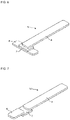
- FIG. 5 shows the extracting electrode 1b in the second embodiment of the present invention.
- the second terminal 6 extends from the PTC element 2 in a direction forming a right angle to the first terminal 4.
- the angle formed by the first terminal 4 and the second terminal 6 does not have to be an exact right angle. For example, it can form an angle from 75 to 105°, preferably from 80 to 100°, and more preferably from 85 to 95°.
- the electrode 1b has a structure similar to that of the first embodiment described above.
- FIG. 3 shows the extracting electrode 1c in the third embodiment of the present invention.
- the second terminal 6 extends from the PTC element 2 in two directions.
- the second terminal 6 forms a right angle with the first terminal 4 in both directions.
- the angle formed by the first terminal 4 and the second terminal 6 in both directions does not have to be an exact right angle. For example, it can form an angle from 75 to 105°, preferably from 80 to 100°, and more preferably from 85 to 95°.
- the electrode 1c has a structure similar to that of the first embodiment described above.
- the two extensions of the second terminal can extend in any direction as long as they form a right angle with the first terminal.
- the second terminal extends in opposite directions.
- the extensions can extend in any direction.
- one extension of the second terminal can extend at a right angle to the first terminal, and the other extension can extend in the opposite direction than the first terminal (forming a 180° angle).
- the second terminal can be straight, bent or, in this case, bent at a right angle.
- the extracting electrode 1d in a fourth embodiment is shown in FIG. 7 .
- the extracting electrode 1d comprises: a PTC element; a first terminal disposed on a portion of one main surface of the PTC element and extending in one direction; and a second terminal disposed on another portion of the main surface apart from the first terminal and extending in a different direction from the first terminal.
- both the first terminal and the second terminal have the same configuration as the first embodiment described above except that they are both present on the same main surface of the PTC element.
- the second terminal may be extended in the same manner as the second and third embodiments described above.
- the PTC element 2 in the present aspect has layered metal electrodes on the main surface connected to the first and second terminals, the layered metal electrode between the first terminal 4 and the PTC element 2 and the layered metal electrode between the second terminal 6 and the PTC element 2 are separated.
- the extracting electrode of the present invention can be used advantageously as an extracting electrode in various rechargeable batteries.
Landscapes
- Engineering & Computer Science (AREA)
- Chemical & Material Sciences (AREA)
- Microelectronics & Electronic Packaging (AREA)
- Chemical Kinetics & Catalysis (AREA)
- Electrochemistry (AREA)
- General Chemical & Material Sciences (AREA)
- Power Engineering (AREA)
- Physics & Mathematics (AREA)
- Manufacturing & Machinery (AREA)
- Electromagnetism (AREA)
- Ceramic Engineering (AREA)
- Materials Engineering (AREA)
- Condensed Matter Physics & Semiconductors (AREA)
- Dispersion Chemistry (AREA)
- General Physics & Mathematics (AREA)
- Inorganic Chemistry (AREA)
- Connection Of Batteries Or Terminals (AREA)
- Sealing Battery Cases Or Jackets (AREA)
Applications Claiming Priority (3)
| Application Number | Priority Date | Filing Date | Title |
|---|---|---|---|
| JP2014247959 | 2014-12-08 | ||
| JP2015100894 | 2015-05-18 | ||
| PCT/JP2015/081973 WO2016093015A1 (fr) | 2014-12-08 | 2015-11-13 | Électrode |
Publications (2)
| Publication Number | Publication Date |
|---|---|
| EP3232496A1 true EP3232496A1 (fr) | 2017-10-18 |
| EP3232496A4 EP3232496A4 (fr) | 2018-06-27 |
Family
ID=56107209
Family Applications (1)
| Application Number | Title | Priority Date | Filing Date |
|---|---|---|---|
| EP15867779.9A Withdrawn EP3232496A4 (fr) | 2014-12-08 | 2015-11-13 | Électrode |
Country Status (7)
| Country | Link |
|---|---|
| US (1) | US20170279107A1 (fr) |
| EP (1) | EP3232496A4 (fr) |
| JP (1) | JPWO2016093015A1 (fr) |
| KR (1) | KR20170068593A (fr) |
| CN (1) | CN107004824A (fr) |
| TW (1) | TW201622213A (fr) |
| WO (1) | WO2016093015A1 (fr) |
Families Citing this family (3)
| Publication number | Priority date | Publication date | Assignee | Title |
|---|---|---|---|---|
| KR102601624B1 (ko) | 2018-06-20 | 2023-11-10 | 주식회사 엘지에너지솔루션 | 개선된 전극 탭들 사이의 연결 구조를 갖는 전극 조립체 |
| JP7469093B2 (ja) * | 2020-03-25 | 2024-04-16 | 本田技研工業株式会社 | リチウムイオン二次電池 |
| CN112968256A (zh) * | 2021-02-03 | 2021-06-15 | 东莞新能安科技有限公司 | 电化学装置和电子装置 |
Family Cites Families (8)
| Publication number | Priority date | Publication date | Assignee | Title |
|---|---|---|---|---|
| JPS61149306U (fr) * | 1985-03-05 | 1986-09-16 | ||
| US20030026053A1 (en) * | 2001-08-06 | 2003-02-06 | James Toth | Circuit protection device |
| KR100477752B1 (ko) * | 2002-12-26 | 2005-03-21 | 삼성에스디아이 주식회사 | 보호소자 및 이를 구비한 리튬 이차 전지 |
| JP4923379B2 (ja) * | 2003-10-27 | 2012-04-25 | ソニー株式会社 | 二次電池および電池パック |
| CN100541867C (zh) * | 2004-04-13 | 2009-09-16 | 株式会社Lg化学 | 包括具有保护器元件的电极引线的电化学装置 |
| KR100624950B1 (ko) * | 2004-10-18 | 2006-09-15 | 삼성에스디아이 주식회사 | 방열층이 형성된 전지 외장재 및 이를 이용한 리튬 폴리머전지 |
| CN201084774Y (zh) * | 2007-08-31 | 2008-07-09 | 比亚迪股份有限公司 | 一种电池保护结构 |
| US9065085B2 (en) * | 2011-04-19 | 2015-06-23 | Samsung Sdi Co., Ltd. | Battery pack |
-
2015
- 2015-11-13 US US15/528,950 patent/US20170279107A1/en not_active Abandoned
- 2015-11-13 WO PCT/JP2015/081973 patent/WO2016093015A1/fr not_active Ceased
- 2015-11-13 EP EP15867779.9A patent/EP3232496A4/fr not_active Withdrawn
- 2015-11-13 CN CN201580061465.0A patent/CN107004824A/zh active Pending
- 2015-11-13 KR KR1020177013478A patent/KR20170068593A/ko not_active Abandoned
- 2015-11-13 JP JP2016563580A patent/JPWO2016093015A1/ja not_active Withdrawn
- 2015-11-30 TW TW104139884A patent/TW201622213A/zh unknown
Also Published As
| Publication number | Publication date |
|---|---|
| WO2016093015A1 (fr) | 2016-06-16 |
| JPWO2016093015A1 (ja) | 2017-09-14 |
| TW201622213A (zh) | 2016-06-16 |
| US20170279107A1 (en) | 2017-09-28 |
| KR20170068593A (ko) | 2017-06-19 |
| CN107004824A (zh) | 2017-08-01 |
| EP3232496A4 (fr) | 2018-06-27 |
Similar Documents
| Publication | Publication Date | Title |
|---|---|---|
| CN104064296B (zh) | 过电流保护元件 | |
| US10342134B2 (en) | Printed circuit board and a method of bonding electrode lead of battery to printed circuit board | |
| JP4006921B2 (ja) | 薄型電池 | |
| CN101728583A (zh) | 保护电路模块和包括该保护电路模块的可再充电电池 | |
| US8842406B2 (en) | Over-current protection device | |
| TWI552418B (zh) | 電極導線及包含其之二次電池 | |
| JP7038946B2 (ja) | バッテリーパック及びこの製造方法 | |
| CN110249452A (zh) | 电池模块及其制造方法 | |
| EP3232496A1 (fr) | Électrode | |
| KR101474395B1 (ko) | 인쇄 회로 기판, 인쇄 회로 기판 연결 구조 및 인쇄 회로 기판 연결 방법 | |
| US9269942B2 (en) | Secondary battery | |
| WO2021235451A1 (fr) | Batterie à électrolyte solide et corps extérieur pour batterie à électrolyte solide | |
| CN105185941A (zh) | 用于电池模块的电气的单池连接器 | |
| CN103021598B (zh) | 过电流保护元件 | |
| US9640326B2 (en) | Solid electrolytic capacitor | |
| JP2023540676A (ja) | 電極リード一体型電極組立体及びその製造方法 | |
| CN104332959B (zh) | 过电流保护装置 | |
| CN220341464U (zh) | 单体电池及具有该单体电池的电池装置 | |
| JP4121358B2 (ja) | 電子機器用の電池パック | |
| JP4955373B2 (ja) | 電池パック | |
| KR101474396B1 (ko) | 인쇄 회로 기판, 인쇄 회로 기판 연결 구조 및 인쇄 회로 기판 연결 방법 | |
| CN201717324U (zh) | 集成有保护装置的充电电池 | |
| JP7154875B2 (ja) | 蓄電素子 | |
| JP2008159351A (ja) | 電池装置 | |
| CN205810499U (zh) | 过电流保护组件 |
Legal Events
| Date | Code | Title | Description |
|---|---|---|---|
| STAA | Information on the status of an ep patent application or granted ep patent |
Free format text: STATUS: THE INTERNATIONAL PUBLICATION HAS BEEN MADE |
|
| PUAI | Public reference made under article 153(3) epc to a published international application that has entered the european phase |
Free format text: ORIGINAL CODE: 0009012 |
|
| STAA | Information on the status of an ep patent application or granted ep patent |
Free format text: STATUS: REQUEST FOR EXAMINATION WAS MADE |
|
| 17P | Request for examination filed |
Effective date: 20170406 |
|
| AK | Designated contracting states |
Kind code of ref document: A1 Designated state(s): AL AT BE BG CH CY CZ DE DK EE ES FI FR GB GR HR HU IE IS IT LI LT LU LV MC MK MT NL NO PL PT RO RS SE SI SK SM TR |
|
| AX | Request for extension of the european patent |
Extension state: BA ME |
|
| DAV | Request for validation of the european patent (deleted) | ||
| DAX | Request for extension of the european patent (deleted) | ||
| A4 | Supplementary search report drawn up and despatched |
Effective date: 20180530 |
|
| RIC1 | Information provided on ipc code assigned before grant |
Ipc: H01M 2/34 20060101AFI20180518BHEP Ipc: H01M 2/06 20060101ALI20180518BHEP Ipc: H01C 1/14 20060101ALI20180518BHEP Ipc: H01M 10/0525 20100101ALI20180518BHEP Ipc: H01C 7/02 20060101ALI20180518BHEP Ipc: H01M 10/0565 20100101ALI20180518BHEP |
|
| STAA | Information on the status of an ep patent application or granted ep patent |
Free format text: STATUS: THE APPLICATION IS DEEMED TO BE WITHDRAWN |
|
| 18D | Application deemed to be withdrawn |
Effective date: 20190103 |