EP3232955B1 - Dispositif chirurgical avec système d'extraction tissulaire incorporé - Google Patents
Dispositif chirurgical avec système d'extraction tissulaire incorporé Download PDFInfo
- Publication number
- EP3232955B1 EP3232955B1 EP15830921.1A EP15830921A EP3232955B1 EP 3232955 B1 EP3232955 B1 EP 3232955B1 EP 15830921 A EP15830921 A EP 15830921A EP 3232955 B1 EP3232955 B1 EP 3232955B1
- Authority
- EP
- European Patent Office
- Prior art keywords
- fluid
- handset
- pump
- tissue
- organ
- Prior art date
- Legal status (The legal status is an assumption and is not a legal conclusion. Google has not performed a legal analysis and makes no representation as to the accuracy of the status listed.)
- Active
Links
Images


Classifications
-
- A—HUMAN NECESSITIES
- A61—MEDICAL OR VETERINARY SCIENCE; HYGIENE
- A61B—DIAGNOSIS; SURGERY; IDENTIFICATION
- A61B17/00—Surgical instruments, devices or methods
- A61B17/32—Surgical cutting instruments
- A61B17/320016—Endoscopic cutting instruments, e.g. arthroscopes, resectoscopes
- A61B17/32002—Endoscopic cutting instruments, e.g. arthroscopes, resectoscopes with continuously rotating, oscillating or reciprocating cutting instruments
-
- A—HUMAN NECESSITIES
- A61—MEDICAL OR VETERINARY SCIENCE; HYGIENE
- A61B—DIAGNOSIS; SURGERY; IDENTIFICATION
- A61B17/00—Surgical instruments, devices or methods
- A61B2017/0023—Surgical instruments, devices or methods disposable
-
- A—HUMAN NECESSITIES
- A61—MEDICAL OR VETERINARY SCIENCE; HYGIENE
- A61B—DIAGNOSIS; SURGERY; IDENTIFICATION
- A61B17/00—Surgical instruments, devices or methods
- A61B2017/0046—Surgical instruments, devices or methods with a releasable handle; with handle and operating part separable
-
- A—HUMAN NECESSITIES
- A61—MEDICAL OR VETERINARY SCIENCE; HYGIENE
- A61B—DIAGNOSIS; SURGERY; IDENTIFICATION
- A61B17/00—Surgical instruments, devices or methods
- A61B17/32—Surgical cutting instruments
- A61B17/320016—Endoscopic cutting instruments, e.g. arthroscopes, resectoscopes
- A61B17/32002—Endoscopic cutting instruments, e.g. arthroscopes, resectoscopes with continuously rotating, oscillating or reciprocating cutting instruments
- A61B2017/320024—Morcellators, e.g. having a hollow cutting tube with an annular cutter for morcellating and removing tissue
-
- A—HUMAN NECESSITIES
- A61—MEDICAL OR VETERINARY SCIENCE; HYGIENE
- A61B—DIAGNOSIS; SURGERY; IDENTIFICATION
- A61B17/00—Surgical instruments, devices or methods
- A61B17/42—Gynaecological or obstetrical instruments or methods
- A61B2017/4216—Operations on uterus, e.g. endometrium
-
- A—HUMAN NECESSITIES
- A61—MEDICAL OR VETERINARY SCIENCE; HYGIENE
- A61B—DIAGNOSIS; SURGERY; IDENTIFICATION
- A61B2217/00—General characteristics of surgical instruments
- A61B2217/002—Auxiliary appliance
- A61B2217/005—Auxiliary appliance with suction drainage system
Definitions
- Endoscopic surgery of a distensible organ may be performed with an endoscope that is insertable into an organ such as the uterus and a resector that passes through the endoscope to cut or otherwise treat tissue in the organ.
- a fluid such as saline, sorbitol, or glycine
- Fluid can be infused into the uterus and removed from the uterus through the endoscope and/or the resector.
- Patents WO 2010/089777 A2 and US 5,456,689A are examples of known similar devices in the field.
- tissue resecting systems include easy-to-handle handsets that compactly integrate a pump and other components for extracting fluid/tissue from an organ.
- a tissue resecting system includes a handset that includes a disposable portion including a pump, a first fluid line, and a second fluid line.
- the pump draws fluid, with suction, from an organ through the first fluid line and moves the fluid into the second fluid line for further processing.
- the handset also includes a reusable portion that is detachably coupled to the disposable portion to define a single housing for the handset.
- the reusable portion includes one or more drive components that drive the pump.
- the system also includes a cutting element that extends from the handset to cut tissue from the organ. This cutting element may also be driven by the one or more drive components in the reusable portion.
- the fluid drawn from the organ by the pump carries tissue that the cutting element cuts from the organ.
- the disposable portion may include a filtration system that filters the fluid drawn from the organ, where the pump moves the fluid through the filtration system and into the second fluid line, which delivers the filtered fluid back to the organ.
- the tissue resecting system may include an endoscope that is configured to be inserted into the organ and to guide the cutting element into the organ.
- the endoscope includes a passageway that is configured to extend into the organ, and the passageway is coupled to the second fluid line to deliver the filtered fluid to the organ.
- the second fluid line may simply deliver the fluid to an external receptacle, for example, for disposal.
- a tissue resecting system in another example implementation, includes a handset that includes a disposable housing including a pump, a first fluid line, a second fluid line, and one or more drive components that drive the pump.
- the pump draws fluid, with suction, from an organ through the first fluid line and moves the fluid into the second fluid line for further processing.
- the tissue resecting system includes a cutting element that extends from the handset to cut tissue from the organ.
- the fluid drawn from the organ by the pump carries tissue cut from the organ by the cutting element.
- the housing may include more than one section.
- the housing may include a first section and a second section, where the first section includes the pump, the first fluid line, and the second fluid line, and the second section includes the one or more drive components.
- the one or more drive components in the reusable portion may include a motor that drives the pump and optionally the cutting element.
- the motor may be powered by an external power source and/or by a battery in the handset.
- implementations structurally integrate various functions of a tissue resecting system into a footswitch. Such integration results in a smaller footprint for the tissue resecting system and makes the system more portable and easier to set up and operate.
- a tissue resecting system includes a resector and a footswitch.
- the resector includes a handset and a cutting element that extends from the handset to cut tissue from the organ.
- the footswitch is coupled to the resector and is selectively operated to activate the cutting element.
- the footswitch includes one or more control elements that control the operation of the cutting element according to selected parameters.
- the footswitch may include a motor that is coupled to and drives the cutting element via a flexible drive shaft, where the one or more control elements control the motor to drive the cutting element.
- the handset may include a pump and a filtration system that recirculates and filters fluid through the organ through fluid lines that pass into the handset.
- the motor of the footswitch also drives the pump with the flexible drive shaft to move the fluid through the recirculation path.
- the pump and filtration system may be disposed externally from the handset. In some cases, the pump and the filtration system are integrated into the footswitch.
- the footswitch may include a user interface with a display and user inputs.
- the user inputs receive the selected parameters employed by the one or more control elements in the footswitch.
- a tissue resecting system comprising: a disposable portion comprising: a handle portion that defines a hub section and a mating section, the handle defines a fluid path that extends through the hub section and the mating section; an elongated shaft coupled to the hub section of the handle portion, the elongated shaft defines an internal flow channel fluidly coupled to the fluid path, and a central axis; an aperture through a distal end of the elongated shaft; a cutting blade within the elongated shaft and in operational relationship to the aperture; a rotating hub disposed within hub section and in operational relationship to a portion of the fluid path within the hub section, the rotating hub defines a drive connector exposed at a transition between the hub section and the mating section; a blade drive shaft that mechanically couples the cutting blade to the rotating hub, the blade drive shaft disposed within the internal flow channel of the elongated shaft and also disposed in the portion of the fluid path in the hub section; a seal in operational relationship to the
- a disposable handset component comprising: a handle portion that defines a hub section and a mating section, the handle defines a fluid path that extends through the hub section and the mating section; an elongated shaft coupled to the hub section of the handle portion, the elongated shaft defines an internal flow channel fluidly coupled to the fluid path, and a central axis; an aperture through a distal end of the elongated shaft; a cutting blade within the elongated shaft and in operational relationship to the aperture; a rotating hub disposed within hub section and in operational relationship to a portion of the fluid path within the hub section, the rotating hub defines a drive connector exposed at a transition between the hub section and the mating section; a drive shaft that mechanically couples the cutting blade to the rotating hub, the drive shaft disposed within the internal flow channel of the elongated shaft and also disposed in the portion of the fluid path in the hub section; a seal in operational relationship to the rotating hub and the hub section, the seal
- a method not forming part of the claimed invention, comprising: disposing a cutting element in proximity to an organ, wherein the cutting element is disposed on a distal end of an elongated shaft being part of a handset that comprises a reusable portion and a disposable portion, wherein the handset is coupled to a power source, a footswitch, a filtration system, and a pump; activating the cutting element by applying power from the power source to the handset, wherein the reusable portion comprises a motor that drives the cutting element; removing, from the organ, fluid and tissue by way a fluid path extending through the disposable portion, wherein the motor is fluidly isolated from the fluid path by a seal and the removed fluid and tissue does not contact with the reusable portion, the removing creates removed fluid; recirculating the removed fluid by: transferring the removed fluid and tissue to the filtration system by way of an outflow line coupled to the handset; filtering the tissue from the removed fluid using the filtration system; and returning to the organ at least some of the removed fluid after
- Drive shaft shall mean a device that transmits energy from a first point (e.g. , a rotational hub) to a second point (e.g., a cutting blade).
- first point e.g. , a rotational hub
- second point e.g., a cutting blade
- the terms “drive shaft” shall not be read to imply any particular structure unless expressly so limited.
- a drive shaft may be implemented as a solid rod, a tube with hollow central axis, an elongated spring, and the like.
- “Detachably coupled” shall mean that two components are designed and constructed to be selectively coupled to each other, and also selectively decoupled from each other, without damage to or destroying either component. Thus, if a first device must be broken, destroyed, or rendered fully or partially inoperable as part of decoupling from the second device, then such devices shall not be considered “detachably coupled” within the meaning of this specification and claims.
- An "elliptical feature” shall mean a feature that defines a closed curve on a plane surrounding two focal points such that the sum of the distances to the two focal points is constant for every point on the curve.
- a circular feature is a special case of the elliptical feature where the two focal points are collocated.
- a footswitch of a device such as a tissue resecting device comprises components enabling device control, device power, and tissue extraction in a foot unit (foot switch) that may be used as an on/off switch in similar devices.
- a handset of the device may comprise a pump (miniature pump), in contrast to other devices that may rely on a pump or other suction source situated in a control unit or otherwise supplied by OR services as a separate unit from the device.
- the pump in the handset may be coupled to a filtration system to recirculate the carrying medium to the body and to capture the removed materials, and in other embodiments the pump may be coupled to an open ended extraction pass where the carrying medium is not recovered (recirculated).
- the device may not operate on a mechanical cutting principle that employs power, in which case a drive motor may be employed for the pump.
- the footswitch may comprise a printed circuit board (PCB) and a transformer, and the controls for the removal process may be housed in a separate display unit that may be located inside or outside of the sterile field.
- the footswitch may include a graphical user display that may be a touch screen and may include control buttons for the display, a motor to drive at least the cutting action may also be included in some embodiments, as may a means of extracting and/or transporting medium.
- the footswitch may further include a means of separating the products of tissue removal from the carrying medium (fluid), and may be configured to return the separated carrying medium to the body and/or contain the tissue or other removal products for further analysis.
- the battery in the footswitch may be configured to carry enough power for procedures within a predetermined time period without recharging, which decreases or eliminates the use of a power cord during the procedure.
- a tissue resecting device comprises a handset that comprises a motor but not a pump and is made up of a disposable part and a reusable part which are fluidly isolated from each other so that the reusable portion is not in contact with the fluid path, or in some embodiments, so that only a portion separate and fluidly isolated from the motor, heat sink, and electronics of the reusable portion is in contact with the fluid.
- the handset comprises the motor to activate the tissue resecting device, a plurality of electronics including a PCB to control the motor, a flow path to transfer fluid from the tissue removal device to external collection containers, a tissue resecting device (e.g., a cutting blade) that simultaneously resects and removes tissue from a target area.
- a vacuum/power unit which may be referred to generically as a control box or external source, comprises a vacuum generator (pump) employed to move fluid from the organ through the tissue resecting device and the disposable part of the handset and into the external collection device, where the power source used to power the motor in the handset is also located.
- the control box may comprise a graphical user interface, which may display various statistics and information regarding the device, the current procedures, and historical procedural information, such as the time that has passed since a procedure began.
- a footswitch may also be coupled to the device, the footswitch may comprise a single pedal for handset motor activation as well as other components as discussed herein.
- the handset may comprise a reusable portion and a disposable portion.
- the reusable portion shares a central axis with the disposable portion, along which they are aligned in order to provide power to a cutting element and establish a fluid path from the target organ to a container for collection and/or disposal.
- the reusable portion of the handset may comprise an outer casing comprising a distal end and a proximal end, the distal end configured to engage with a proximal portion of a connector of the disposable portion.
- the outer casing may also comprise a plurality of mating features including rails that are intended to mate with a guide track of the disposable portion along a shared (common) central axis.
- the outer casing of the reusable portion may comprise a plurality of tabs or other features located on the distal end and on a first and a second side, these tabs may be configured to mate with features of the disposable portion.
- disposed in the outer casing of the reusable portion are a motor and a heat sink (which may be collectively referred to herein as the motor), as well as a plurality of electronics.
- the disposable portion may comprise a distal end comprising a housing coupled to a cutting element or other instrument and a proximal end configured to be coupled to a sample collection, filtration, or other fluid and/or tissue receptor or fluid recirculation device.
- the disposable portion comprises a fluid path that moves fluid and/or tissue from the organ through the handset and on to the sample collection, filtration, or other fluid and/or tissue receptor or fluid recirculation device without contacting the reusable portion.
- the fluid path in the disposable portion is fluidly isolated from the reusable portion and extends from the distal end of the handset through a rotating hub to a proximal end of the disposable portion.
- the seal separates the fluid flow from the motor and heat sink and electronics, which may eliminate the need for an autoclaving procedure in between surgical procedures.
- a disposable portion may be attached to the reusable portion, a procedure performed, the disposable portion may be removed, disposed, and the reusable portion may be cleaned by spraying, wiping, or other means, and the reusable portion is prepared (cleaned) for a subsequent surgery with a new disposable portion without being sterilized (by autoclave or otherwise), since the non-sterile fluid and tissue in the disposable portion do not come in contact with the reusable portion.
- the fluid path comprises a first portion extending from the distal end of the disposable portion to a rotating hub of the reusable portion, where a seal is disposed as discussed above.
- the fluid path does not take a 90 degree turn with respect to the central axis, but rather comprises a second portion disposed before the end of the first portion and comprising a smooth angled transition. After the transition, the second portion extends parallel to the central axis towards the proximal end of the disposable portion where the fluid and/or tissue are collected/disposed/recirculated, depending upon the embodiment.
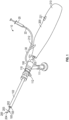
- a tissue resecting system 10 includes an endoscope 100 (e.g., a hysteroscope), which includes an endoscope body 110 and an insert portion 102 that extends from the endoscope body 110 to a distal end thereof.
- the endoscope insert portion 102 is insertable into an organ, (e.g., a uterus) of a patient to enable a tissue resecting procedure in the organ.
- the tissue resecting system 10 also includes a resector 200 that is received by the endoscope 100 to resect tissue from the organ.
- the resector 200 includes a handset 210 that is disposed at a proximal end of the endoscope body 110.
- the resector 200 also includes a shaft 202 that extends from the handset 210 and passes correspondingly through the endoscope body 110 and the endoscope insert portion 102.
- the shaft 202 includes a cutting element 204, (e.g., a hysteroscopic tissue removal device).
- the cutting element 204 is disposed beyond the distal end of the endoscope insert portion 102 to access tissue in the organ.
- the handset 210 includes a motor (not shown) that is coupled to and drives the cutting element 204 to cut tissue from the organ.
- a motor discussed below in FIG. 2 , may actuate/rotate and/or linearly move the cutting element 204 in a back-and-forth motion to generate a cutting action.
- the endoscope 100 includes an inlet port 101 that is coupled to a main inflow line 30, which delivers fluid, (e.g., saline, sorbitol, glycine, etc.) to the endoscope 100.
- An endoscope inflow passageway 103 is formed in the endoscope 100 and extends from the inlet port 101 to an inflow opening 105 at the distal end of the endoscope insert portion 102.
- the main inflow line 30 receives fluid from a fluid source 20 (e.g., a syringe or other device) that provides the fluid under some pressure, through a source inflow line 22.
- a fluid source 20 e.g., a syringe or other device
- the endoscope 100 may include a seal (e.g., a cervix seal) disposed about the endoscope insert portion 102 to close the opening to the organ when the endoscope insert portion 102 is inserted into the organ and to minimize the amount of fluid loss from the organ and the closed loop of the tissue resecting system 10.
- a seal e.g., a cervix seal
- the resector 200 includes an outflow opening 205 at the cutting element 204.
- An outflow passageway 203 extends from the outflow opening 205, through the shaft 202, and into the handset 210.
- the handset 210 applies suction through the outflow passageway 203.
- the cutting element 204 cuts tissue from the organ, the suction draws fluid as well as cut tissue and other byproducts (e.g., blood, etc.) from the cutting process through the outflow opening 205.
- the fluid, tissue, and byproducts then flow through the outflow passageway 203 and into the handset 210.
- the handset 210 may be coupled to an outflow passageway formed in the endoscope insert portion 102 (rather than the shaft 202) and the suction extracts the fluid, tissue, and other byproducts through this alternative outflow passageway formed in the endoscope insert portion 102.
- the handset 210 After receiving the fluid, tissue, and other byproducts from the organ through the outflow passageway 203, the handset 210 filters the fluid to remove the tissue and other byproducts.
- the handset 210 includes an inflow line 212 that is coupled to the main inflow line 30 to deliver the filtered fluid back to the main inflow line 30.
- the main inflow line 30 receives fluid from the handset 210 as well as the fluid source 20.
- the filtered fluid flows through the inflow passageway 103 of the endoscope 100 and into the organ.
- the handset 210 includes a pump that recirculates the fluid through the tissue resecting system 10 and the organ.
- the handset 210 includes a filtration system that removes tissue and other byproducts from the recirculating fluid.
- the handset 210 includes a control switch/button 221 that activates the pump and/or the cutting element 204.
- the handset 210 may also include a battery.
- the pump and/or the cutting element 204 may be activated by an external footswitch coupled to the handset 210.
- fluid is introduced into the system through the source inflow line 22 from the fluid source 20.
- the fluid from the source inflow line 22 flows through the main inflow line 30, the inlet port 101, the inflow passageway 103, and the inflow opening 105 and into the organ.
- the fluid, tissue, and other byproducts produced by the cutting element 204 are then drawn from the organ through the outflow opening 205, the outflow passageway 203, and into the handset 210.
- the fluid is filtered in the handset 210 and flows through the inflow line 212 and back into the main inflow line 30.
- the handset 210 illustrated in FIG. 1 is configured to extract fluid from an organ and filter the fluid for delivery back into the organ. Recirculating the fluid in this manner minimizes the amount of working fluid required for a procedure.
- Fluid from the fluid source 20 can also be subsequently introduced to the tissue resecting system 10 to maintain an amount of fluid in the system, for example, in the event of some leakage.
- the handset 210 integrates many of the components required for recirculating fluid through an organ as well as cutting and extracting tissue from the organ.
- the configuration of the handset 210 makes the tissue resecting system 10 highly portable and easier to set up.
- less fluid is required to create the necessary flow through the endoscope 100 and the resector 200.
- the fluid can be more easily managed to maintain fluid pressure inside the organ, for example, for distension.
- the amount of fluid can be more easily monitored to ensure undesired/excessive absorption of fluid into the body does not occur.
- the endoscope 100 may also accommodate other devices for various procedures.
- the endoscope 100 includes a camera port 111 and a light port 112 that may be coupled to a camera (not shown) and an illumination source (not shown), respectively. Together, the camera and the illumination source allow the operator to visualize and capture images from the area around the distal end of the tissue resecting system 10.
- the endoscope 100 is shown as an example, and that other similar devices (with fewer or more features) can be employed according to aspects of the present disclosure, for example, to accommodate the resector 200.
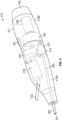
- the handset 310 may be employed in the tissue resecting system 10 (e.g., in some implementations the handset 210 is the handset 310 shown in FIG. 2 ).
- the handset 310 includes a housing 311 that contains many of the components required for cutting and extracting tissue from an organ and recirculating fluid through the organ.
- the housing 311 is defined by a disposable portion 310A and a reusable portion 310B.
- the disposable portion 310A and the reusable portion 310B may be detachably coupled to each other by threaded engagement, snap-fit, frictional engagement, pins, fasteners, tape (adhesive), etc.
- the disposable portion 310A is intended to be discarded after only one use. Meanwhile, the reusable portion 310B includes components that can be used more than one time. After each use, the disposable portion 310A is detached from the reusable portion 310B and discarded, but the same reusable portion 310B can be coupled to a new disposable portion similar to 310A for another use. Each disposable portion 310A may be individually and sterilely packaged. Allowing the section 310A to be disposable promotes hygienic use of the tissue resecting system 10 (e.g., including the handset 310), because it eliminates any need to clean and sterilize the disposable portion 310A after it has been contaminated, for example, by contact with fluid and tissue from a patient.
- the tissue resecting system 10 e.g., including the handset 310
- the tissue resecting system 10 provides the convenience of disposable components while avoiding the costs of a completely disposable handset, thus increasing efficiency and safety in the OR without increasing cost.
- the handset 310 includes a shaft 302 that has a cutting element at a distal end. Similar to the implementation shown in FIG. 1 , the handset 310 in FIG. 2 receives fluid from the organ and then returns filtered fluid to the organ through an inflow line 312. As shown in FIG. 2 , the shaft 302 extends from the housing 311 of the handset 310. Like the shaft 202 described above, the shaft 302 provides an outflow passageway 303 that delivers the fluid, tissue, and other byproducts into the handset 310. The shaft 302 is coupled to a chamber 313 where the fluid, tissue, and other byproducts are drawn from the outflow passageway 303.
- the handset 310 includes a pump 316 inside the housing 311.
- the pump 316 is coupled to the chamber 313 via an outflow line 314.
- the pump 316 is capable of producing sufficient suction at the distal end of the resector to draw the fluid from the organ and through the outflow passageway 303, the chamber 313, and the outflow line 314.
- the pump is sufficiently compact to permit the handset 310 to have a convenient size and an ergonomic shape for easy handling.
- the pump 316 may be a positive displacement pump, such as a gear pump, a diaphragm pump, a peristaltic pump, a cavity pump, a lobe pump, a piston pump, or the like.
- the magnitude of suction depends on the cutting device, the nature of tissue being cut, and the hydraulic resistance in the extraction path.
- the suction for example, may be produced with a vacuum of approximately 100 mmHg to approximately 500 mmHg. It is understood, however, that the vacuum may be provided according to a range, for example, with a maximum greater than 500 mmHg, as required by the operation of the tissue resecting system.
- the handset 310 also includes a filtration system 318.
- the pump 316 is coupled to the filtration system 318 via a connecting line 317. Accordingly, the fluid from the outflow line 314 is drawn through the pump 316 and to the filtration system 318 via the connecting line 317.
- the filtration system 318 includes a filter/tissue trap that removes the tissue and other byproducts from the fluid received by the handset 310. The filter/tissue trap may be removable or otherwise accessible to allow the tissue from the organ to be collected and examined.
- the filtration system 318 is coupled to the inflow line 312 which allows filtered fluid to be returned to the organ via an endoscope (e.g., endoscope 100) as described above.
- an endoscope e.g., endoscope 100
- the components inside the housing 311 may be configured differently so that the pump 316 is downstream of the filtration system 318 and pulls, rather than pushes, the fluid through the filtration system 318.
- the outflow line 314, the pump 316, the connecting line 317, the filtration system 318, and the inflow line 312 are contained in the disposable portion 310A. These components are contaminated by contact with fluid and tissue from the body. As such, the ability to dispose of them after a single use enhances the convenience of using the handset 310. Because the shaft 302 (with the outflow passageway 303 and the cutting element) also comes into direct contact with the fluid and tissue from the body, it is also conveniently disposable with the other components in the disposable portion 310A.
- the handset 310 includes a motor 320 to drive the pump 316.
- the motor 320 is electrically coupled to an external power source, for example, a DC power, via a cable 322.
- an external power source for example, a DC power
- the tissue extraction and fluid recirculation by the pump 316 and the cutting operation occur at the same time, so the same motor 320 can be used for the pump 316 and the cutting element.
- the motor 320 drives the shaft 302 to generate cutting action with the cutting element (e.g., rotating and/or linearly moving the cutting element in a back-and-forth motion to generate the cutting action).
- the fluid flow from the pump can be controlled independently from the cutting operation with the cutting element.
- the handset 310 can include a gear box and clutch 324 that divides the drive from the motor 320 between the pump 316 and the shaft 302.
- the handset 310 includes a control switch/button 321 that activates the pump 316 and/or the shaft 302 (and the attached cutting element).
- the motor 320 runs and drives the pump 316 constantly whenever the cable 322 is coupled to the external power source.
- the control switch/button 321 is selectively operated by the user to engage a clutch that delivers drive from the motor 320 to the shaft 302.
- the handset 310 constantly recirculates fluid through the organ, while the user selectively presses the control switch/button 321 to cut tissue from the organ.
- one control switch/button may be employed to activate fluid recirculation with the pump 316, while another control switch/button may be employed to independently and selectively activate the cutting element.
- the user presses the control switch/button 321 to activate the pump 316 and the cutting element simultaneously.
- other controls and user interfaces may be provided to control other aspects of the tissue resecting system 10.
- the motor 320 and the gear box and clutch 324 are not contaminated by contact with fluid and tissue drawn from the organ, these components can be reused more easily. As such, the motor 320 and the gear box and clutch 324 are positioned in the reusable portion 310B. In some cases, these components may be more costly than those in the disposable portion 310A. As such, reusing the motor 320 and the gear box and clutch 324 reduces the marginal cost of using the tissue resecting system 10.
- the reusable portion 310B may be cleaned and/or sterilized before it is used again.
- FIG. 3 another example handset 410 is illustrated having a disposable portion 410A and a reusable portion 410B.
- the handset 410 is similar to the handset 310 described above and includes many of the same components, where like reference numerals indicate like elements across the Figures. Indeed, like the handset 310 in FIG. 2 , the handset 410 may be employed in the tissue resecting system 10.
- the handset 410 does not receive power from an external power source. As shown in FIG. 3 , the handset 410 does not include a cable that extends outwardly to an external power source.
- the handset 410 includes a battery 422 that is coupled to and powers a motor 420, which in turn drives the pump 316 and the shaft 302 via the gear box and clutch 324, as described above.
- the battery 422 may be a non-rechargeable battery that must be replaced once its power has been depleted. In other embodiments, the battery 422 may be a rechargeable battery that can be coupled to another power source to be replenished.
- the battery 422 is conveniently and removably attached to the proximal end of the reusable portion 410B of the handset 410.
- the handset 410 has a housing 411 that is defined by a differently configured reusable portion 410B.
- the handset 410 is easier to use as compared with the handset 310 because the motion of the handset 410 is not restricted by a cable that is connected to an external power source.
- FIG. 4 another example handset 510 is illustrated having a disposable portion 510A and a reusable portion 510B.
- the handset 510 includes many of the same components of the handsets 310 and 410, where like reference numerals indicate like elements across the Figures. Unlike the handsets 310 and 410, however, the handset 510 does not filter and/or recycle the fluid received from the organ.
- the handset 510 includes a pump 516 that draws fluid/tissue from the organ through the outflow line 314, but the pump 516 does not direct the fluid/tissue to a filtration system and back to the organ. Rather, the fluid/tissue is directed from the handset 510 through an external line 512 to an external receptacle where the fluid/tissue can be collected for disposal, examination, etc.
- the handset 510 provides open-ended extraction.
- the handset 510 includes a housing 511 that is defined in part by the disposable portion 510A, which has a different configuration as compared with the handsets 310, 410.
- the implementations provide examples of tissue resecting systems that include easy-to-handle handsets that compactly integrate a pump and other components for extracting fluid/tissue from an organ.
- the handsets include a filtration system to allow fluid to be recirculated through the organ.
- the handsets include a disposable portion that allows components that contact the fluid/tissue (e.g., the pump) to be easily disposed, thereby promoting hygienic use of the tissue resecting system.
- the handsets include a reusable portion that allows other components (e.g., drive components) to be used more than once, thereby achieving cost savings.
- the handset may include a housing that is defined by more than one disposable portion.
- the handset 610 includes a housing 611 that houses the chamber 313, the outflow passageway 314, the pump 516, the gear box and clutch 324, the motor 320, and a battery 622. Like the handset 510 described above, the handset 610 does not filter and recirculate fluid drawn from the organ. In other words, the handset 610 provides open-ended extraction. Driven by the motor 320 via the gear box and clutch 324, the pump 516 draws the fluid, tissue, and other byproducts from the organ into the handset 610 through the outflow passageway 303 and out of the handset 610 through the external line 512.
- the housing 611 of the handset 610 is not divided into a disposable portion and a reusable portion. Rather, the handset 610 is configured to be completely disposable.
- the motor 320 and the battery 622 are disposable with the other components of the handset 610.
- handset 610 may include a low-cost motor and a low-cost battery that make single or limited use of the handset 610 less prohibitive. Therefore, the handset 610 is configured for limited, for example, single, use and convenient disposal.
- the handset 610 promotes hygienic use of the tissue resecting system 10, because it eliminates any need to clean and sterilize any of its components after it has been contaminated, for example, by contact with fluid and tissue from the patient.
- the motor in the handset only drives the pump.
- separate motors may be employed to drive the pump and the cutting element, respectively.
- the motor may be disposed externally and coupled to the handset via a rigid or flexible drive shaft, where the handset includes drive components (e.g., gear box and clutch) that deliver the driving force from the motor to the pump, etc.
- an operator may have the option of selectively coupling the same disposable portion 310A with either the reusable portion 310B (external power source) or the reusable portion 410B (onboard battery power).
- an operator may have the option of selectively coupling the same reusable portion 310B with either the disposable portion 310A (fluid filtration/recirculation) or the disposable portion 510A (open-ended extraction, no fluid filtration/recirculation).
- implementations described herein may include an endoscope through which a resector passes, it is contemplated that, in other applications, resectors according to aspects of the present disclosure do not pass through a working channel of an endoscope and instead may be employed outside an endoscope (e.g., work along with the endoscope).
- a tissue resecting system 10 includes an endoscope 100 (e.g., a hysteroscope), which includes an endoscope body 110 and an insert portion 102 that extends from the endoscope body 110 to a distal end.
- the endoscope insert portion 102 is insertable into an organ (e.g., a uterus, a prostate, etc.) of a patient to enable a tissue resecting procedure in the organ.
- the tissue resecting system 10 also includes a resector 200 that is received by the endoscope 100 to resect tissue from the organ.
- the resector 200 includes a handset 210 that is disposed at a proximal end of the endoscope body 110.
- the endoscope 100 may also accommodate other devices for the procedure.
- the endoscope 100 includes a camera port 114 and a light port 112 that may be coupled to a camera (not shown) and an illumination source (not shown), respectively. Together, the camera and the illumination source allow the operator to visualize and capture images from the area around the distal end of the tissue resecting system 10.
- the endoscope 100 is shown as an example, and that other similar devices (with fewer or more features) can be employed according to aspects of the present disclosure (e.g., to accommodate the resector 200).
- the endoscope 100 includes an inlet port 101 that is coupled to a main inflow line 30, which delivers fluid (e.g., saline, sorbitol, glycine, etc.) to the endoscope 100.
- An endoscope inflow passageway 103 is formed in the endoscope 100 and extends from the inlet port 101 to an inflow opening 105 at the distal end of the endoscope insert portion 102.
- the main inflow line 30 receives fluid from a fluid source 20 (e.g., a syringe) through a source inflow line 22. The fluid then flows from the main inflow line 30, through the inlet port 101, the inflow passageway 103, and the inflow opening 105, and into the organ at the distal end of the endoscope 100.
- a fluid source 20 e.g., a syringe
- the tissue resecting system 10 includes a pump that recirculates the fluid through the tissue resecting system 10 and the organ.
- the tissue resecting system 10 includes a filtration system that removes tissue and other material from the recirculating fluid. After receiving the fluid/tissue from the organ through the outflow line 214, the tissue resecting system 10 filters the tissue from the fluid.
- the handset 210 includes an inflow line 212 that is coupled to the main inflow line 30 to deliver the filtered fluid back to the main inflow line 30.
- the main inflow line 30 receives fluid from the handset 210 as well as the fluid source 20.
- the filtered fluid flows through the inflow passageway 103 of the endoscope 100 and into the organ.
- tissue resecting system 10 fluid is introduced into the tissue resecting system 10 through the source inflow line 22.
- the fluid from the source inflow line 22 flows through the main inflow line 30, the inlet port 101, the inflow passageway 103, and the inflow opening 105 and into the organ.
- the fluid and tissue is then drawn from the organ through the outflow opening 205, the outflow passageway 203, the outflow line 214, and into the handset 210.
- the fluid is filtered and flows through the inflow line 212 and back into the main inflow line 30.
- the tissue resecting system 10 illustrated in FIG. 6 is configured to extract fluid from an organ and filter the fluid for delivery back into the organ. Recirculating the fluid in this manner minimizes the amount of working fluid required for a procedure.
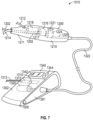
- the footswitch 300 is configured to minimize the footprint of the tissue resecting system 10. Rather than employing a separate controller device (e.g., computer) to control the pump (e.g., pump 1320 in FIG. 7 ) and/or the cutting element 204, the tissue resecting system 10 houses control elements 310 in the footswitch 300.
- the control elements 310 may include one or more printed circuit board (PCB) assemblies with one or more processors that control aspects of the tissue resecting system 10 according to stored program instructions and input parameters.
- PCB printed circuit board
- the control elements 310 may cause the cutting element 204 to operate according to a selected cutting speed and/or may cause the pump to recirculate the fluid in the tissue resecting system 10 according to a selected flow rate.
- the footswitch 300 also contains a suitably rated electrical transformer 312 to convert the main electrical supply into suitable voltages for powering and controlling aspects of the tissue resecting system 10.
- the footswitch 300 may receive electrical power from an external source via an electrical cable 313.
- the footswitch 300 (and the other implementations described herein) may house a battery of sufficient capacity (e.g., a rechargeable battery) to remove the need for an electrical connection to an external source.
- the tissue resecting system 10 includes a separate user interface 400 that allows the user to monitor the operation of the tissue resecting system 10 and to enter any information required for the tissue resecting process.
- the user may employ the user interface 400 to set parameters for the control elements 310 housed in the footswitch 300.
- the user interface 400 includes a display screen 410 as well as user inputs 420 (e.g., pushbuttons, switches, etc.).
- the user interface 400 may include a touch screen.
- the user may set a cutting speed for the cutting element 204 and/or set a flow rate for the recirculation of fluid through the tissue resecting system 10.
- the parameter settings and other input information are communicated to the footswitch 300 for use by the control elements 310.
- the selected parameters are displayed on the user interface 400 along with any feedback information from the control elements 310.
- the communication between the footswitch 300 and the user interface 400 occurs over a wireless connection (e.g., via radio frequency (RF) technology, such as BLUETOOTH ® , etc.).
- RF radio frequency
- the user interface 400 can be easily positioned in a desired location, for example, within reach of the surgeon in the sterile field or within reach of an assistant outside the sterile field, without needing to arrange inconvenient cables or wires.
- the footswitch 300 and the user interface 400 may communicate over a wired connection.
- a footswitch can integrate many of the components required for recirculating fluid through an organ as well as cutting and extracting tissue from the organ.
- the configuration of the footswitch makes the tissue resecting system 10 highly compact, portable, and easy to set up and operate.
- the tissue resecting system 1010 includes a resector 1200, which may be combined with an endoscope (not shown) that is the same as, or similar to, the endoscope 100 of FIG. 6 .
- the resector 1200 includes a handset 1210 with a housing 1211 that contains many of the components required for cutting and extracting tissue from an organ and recirculating fluid through the organ.
- the resector 1200 also includes a cutting shaft 1202 that extends distally from the handset 1210 and through the endoscope.
- the cutting shaft 1202 is employed to generate a cutting action (e.g., translating, rotating, reciprocating, or any combination thereof) with a distal cutting element (not shown), which is positioned within an organ by the endoscope.
- the handset 1210 includes an outflow line 1214 that receives fluid from the organ and an inflow line 1212 that returns filtered fluid to the organ.
- the handset 1210 includes a pump 1216 inside the housing 1211.
- the pump 1216 is coupled to the outflow line 1214 which extends into the housing 1211.
- the pump 1216 is capable of producing sufficient suction at the distal end of the resector to draw the fluid from the organ and through the outflow line 1214.
- the pump 1216 is sufficiently compact to permit the handset 1210 to have a convenient size and an ergonomic shape for easy handling.
- the pump 1216 may be a positive displacement pump, such as a gear pump, a diaphragm pump, a peristaltic pump, a cavity pump, a lobe pump, a piston pump, or the like.
- the magnitude of suction depends on the cutting device, tissue nature, and the hydraulic resistance in the extraction path.
- the suction for example, may be produced with a vacuum of approximately 100 mmHg to approximately 500 mmHg.
- the handset 1210 also includes a filtration system 1218.
- the pump 1216 is coupled to the filtration system 1218 via a connecting line 1217. Accordingly, the fluid from the outflow line 1214 is drawn through the pump 1216 and to the filtration system 1218 via the connecting line 1217.
- the filtration system 1218 includes a filter/tissue trap that removes the tissue and other material from the fluid received by the handset 1210. The filter/tissue trap may be removable or otherwise accessible to allow the tissue from the organ to be collected and examined.
- the filtration system 1218 is coupled to the inflow line 1212, which allows filtered fluid to be returned to the organ via an endoscope as described herein. While the filtration system 1218 is shown as being downstream from the pump 1216, in alternative implementations, the filtration system 1218 can be positioned upstream of the pump 1216, such that the fluid is filtered prior to reaching the pump 1216.
- the tissue resecting system 1010 includes a footswitch 1300.
- the footswitch includes a motor 1320 to drive the pump 1216.
- the tissue extraction and fluid recirculation by the pump 1216 and the cutting operation occur at the same time, so the same motor 1320 can be used for the pump 1216 and the cutting element.
- the motor 1320 drives the cutting shaft 1202 to generate the cutting action with the cutting element.
- the handset 1210 includes a gear box and clutch 1224 that divides the drive from the motor 1320 between the pump 1216 and the cutting shaft 1202.
- the motor 1320 is coupled to a proximal end of the handset 1210 and drives the gear box and clutch 1224 via a flexible drive shaft 1322.
- the flexible drive shaft 1322 is coupled to the gear box and clutch 1224 via a connecting drive shaft 1225.
- the flexibility of the drive shaft 1322 provides sufficient freedom of motion to permit the resector 1200 to be freely manipulated.
- the footswitch 1300 includes a body 1301 with an upper surface 1302. Similar to the footswitch 300 of FIG. 6 , the user applies a force against the upper surface 1302 (e.g., with his/her foot) to operate the footswitch 1300. Mechanical action resulting from the force against the upper surface 1302 generates an electrical signal that delivers power to and drives the motor 1320, which in turn drives the flexible drive shaft 1322. In some implementations, the user must apply continuous pressure to the upper surface 1302 to drive the motor 1320 continuously. In other implementations, the user applies a force to turn on the power that continuously drives the motor 1320, and the user subsequently applies a separate force to turn off the power to and stop the motor 1320.
- the upper surface 1302 e.g., with his/her foot
- Mechanical action resulting from the force against the upper surface 1302 generates an electrical signal that delivers power to and drives the motor 1320, which in turn drives the flexible drive shaft 1322.
- the user must apply continuous pressure to the upper surface 1302 to
- the footswitch 1300 also includes control elements 1310 (e.g., PCB assemblies with one or more processors).
- control elements 1310 allow the motor 1320 and thus the flexible drive shaft 1322 to be driven according to selected parameters, such as revolutions per minute (RPM), which in turn determine how the pump 1216 and the cutting element operate.
- RPM revolutions per minute
- the handset 1210 includes a control switch/button 1221 that activates the pump and/or the cutting shaft 1202 while the flexible drive shaft 1322 is being driven by the motor 1320.
- the control switch/button 1221 is selectively operated by the user to engage the gear box and clutch 1224 to deliver drive from the flexible drive shaft 1322 to the cutting shaft 1202 and to the pump 1216.
- one control switch/button may be employed to activate fluid recirculation with the pump 1216, while another control switch/button may be employed to independently and selectively activate the cutting shaft 1202.
- Other controls may be provided on the handset 1210 to control other aspects of the tissue resecting system.
- the motor 1320 is disposed in the footswitch 1300, it can be reused with the footswitch 1300.
- the flexible drive shaft 1322 can be decoupled from the handset 1210, and because it does not become contaminated by direct contact with fluid and tissue from the patient, it too can be reused.
- the motor 1320 and the flexible drive shaft 1322 may be more costly than the other components of the resector 1200. As such, reusing the motor 1320 and the flexible drive shaft 1322 advantageously reduces the marginal cost of using the tissue resecting system 1010.
- the footswitch 1300 and/or the flexible drive shaft 1322 may require cleaning/sterilization before they are used again.
- the resector 1200 includes components that come into direct contact with fluid and tissue from the patient. Such components include the cutting element, the cutting shaft 1202, the outflow line 1214, the pump 1216, the connecting line 1217, the filtration system 1218, and the inflow line 1212.
- the resector 1200 can be conveniently decoupled from the flexible drive shaft 1322 and discarded, while the same flexible drive shaft 1322 and footswitch 1330 can be coupled to a new resector 1200 for another use. Allowing the resector 1200 to be disposable promotes hygienic use of the tissue resecting system 1010, because it eliminates the need to sterilize the resector 1200 after it has been contaminated.
- the tissue resecting system 1010 provides the convenience of disposable components while avoiding the costs of a system that requires disposal of more costly components that do not come into direct contact with fluid and tissue from the patient.
- the footswitch 1300 also includes a user interface 1340 that eliminates the need for a separate user interface, such as the user interface 400 shown in FIG. 6 .
- the user interface 1340 allows the user to monitor the operation of the tissue resecting system 1010 and to enter any information required for the tissue resecting process.
- the user interface 1340 includes a display screen 1342 as well as user inputs 1344 (e.g., pushbuttons, switches, etc.). Alternatively or additionally, the user interface 1340 may include a touch screen. The user may employ the user interface 1340 to set parameters for the control elements 1310 housed in the footswitch 1300.
- the user may set a cutting speed for the cutting element and/or set a flow rate for the recirculation of fluid through the tissue resecting system 1010.
- the selected parameters are displayed on the user interface 1340 along with any feedback from the control elements 1310.
- the information displayed on the user interface 1340 is sufficiently visible even when the footswitch 1300 is placed on the floor for operating the tissue resecting system 1010.
- the user inputs 1344 are designed to be readily operated by the foot of the user. By incorporating the user interface 1340 into the footswitch 1300, even fewer separate components are required for the tissue resecting system 1010. Again, the configuration of the footswitch 1300 makes the tissue resecting system 1010 highly compact, portable, and easy to deploy and operate.
- the tissue resecting system 2010 includes a resector 2200, which may be combined with an endoscope (not shown) that is, the same as, or similar to, the endoscope 100 of FIG. 6 .
- the resector 2200 includes a handset 2210 with a housing 2211.
- the resector 2200 also includes a cutting shaft 2202 that extends distally from the handset 2210 and through the endoscope.
- the cutting shaft 2202 is employed to generate a cutting action (e.g., translating, rotating, reciprocating, or any combination thereof) with a distal cutting element (not shown), which is positioned within an organ by the endoscope.
- the handset 2210 includes an outflow line 2214 that receives fluid from the organ and an inflow line 2212 that returns filtered fluid to the organ.
- the handset 2210 does not includes a pump or filtration system in the housing 2211.
- the tissue resecting system 2010 includes a pump 2500 and a filtration system 2600 that are separate components disposed outside the housing 2211.
- the pump 2500 is coupled to the handset 2210 via a pump line 2510.
- the pump line 2510 is removably coupled to a proximal end of the handset 2210 where it is connected to the outflow line 2214, which extends through the housing 2211 of the handset 2210.
- the pump 2500 is capable of producing sufficient suction to draw the fluid from the organ and through the outflow line 2214 and the pump line 2510.
- the pump 2500 may be a positive displacement pump, such as a gear pump, a diaphragm pump, a peristaltic pump, a cavity pump, a lobe pump, a piston pump, or the like.
- the magnitude of suction depends on the cutting device, tissue nature, and the hydraulic resistance in the extraction path.
- the pump 2500 is coupled to the filtration system 2600. Accordingly, the fluid from the outflow line 2214 is drawn through the pump line 2510 by the pump 2500 and to the filtration system 2600.
- the filtration system 2600 includes a filter/tissue trap that removes the tissue and other material from the fluid received by the handset 2210. The filter/tissue trap may be removable or otherwise accessible to allow the tissue from the organ to be collected and examined.
- the filtration system 2600 is coupled to the handset 2210 via a filtration system line 2610.
- the filtration system line 2610 is removably coupled to the proximal end of the handset 2210 where it is connected to the inflow line 2212, which also extends through the handset 2210.
- the filtration system line 2610 allows filtered fluid to be returned to the inflow line 2212 and to the organ via an endoscope as described above.
- the tissue resecting system 2010 includes a footswitch 2300.
- the footswitch includes a motor 2320 to drive the pump 2500 as well as the cutting shaft 2202 to generate the cutting action with the cutting element.
- the fluid flow from the pump 2500 can be controlled independently from the cutting operation with the cutting shaft 2202.
- the footswitch 2300 includes a gear box and clutch 2324 that divides the drive from the motor 2320 between the pump 2500 and the cutting shaft 2202.
- the gear box and clutch 2324 is coupled to and drives the pump 2500 via a flexible pump drive shaft 2323.
- the flexibility of the pump drive shaft 2323 provides sufficient freedom of motion to permit the pump 2500 to be conveniently positioned relative to the footswitch 2300.
- the gear box and clutch 2324 is coupled to and drives the cutting shaft 2202 via a flexible cutting drive shaft 2322.
- the flexible cutting drive shaft 2322 is removably coupled to the proximal end of the handset 2210 where it is connected to the cutting shaft 2202, which extends through the housing 2011 of the handset 2210.
- the flexibility of the drive shaft 2322 provides sufficient freedom of motion to permit the resector 2200 to be freely manipulated.
- the footswitch 2300 includes a body 2301 with an upper surface 2302.
- the user applies a force against the upper surface 2302 (e.g., with his/her foot) to operate the footswitch 2300.
- Mechanical action resulting from the force against the upper surface 2302 generates an electrical signal that delivers power to and drives the motor 2320, which in turn drives the flexible cutting drive shaft 2322 and the flexible pump drive shaft 2323.
- the footswitch 2300 also includes control elements 2310 (e.g., one or more PCB assemblies with one or more processors).
- control elements 2310 allow the motor 2320 and thus the flexible cutting drive shaft 2322 and the flexible pump drive shaft 2323 to be driven according to selected parameters, such as revolutions per minute (RPM), which in turn determine how the cutting shaft 2202 and the pump 2500 operate.
- RPM revolutions per minute
- the footswitch 2300 is selectively operated by the user to engage the gear box and clutch 2324 to deliver drive to the flexible cutting drive shaft 2322 and the flexible pump drive shaft 2323. As shown in FIG. 8 , the footswitch 2300 receives electrical power from an external source via an electrical cable 2313 and includes an electrical transformer 2312 to convert the main electrical supply into suitable voltages for powering and controlling aspects of the tissue resecting system 2010.
- the footswitch 2300 also includes a user interface 2340 that eliminates the need for a separate user interface, such as the user interface 400 shown in FIG. 6 .
- the user interface 2340 allows the user to monitor the operation of the tissue resecting system 2010 and to enter any information required for the tissue resecting process (e.g., set parameters for the control elements 2310 housed in the footswitch 2300).
- the user interface 2340 includes a display screen 2342 as well as user inputs 2344 (e.g., pushbuttons, switches, etc.). Alternatively or additionally, the user interface 2340 may include a touch screen.
- the motor 2320, the flexible drive shaft 2322, and the flexible pump drive shaft 2323 can be reused, while other components that come into direct contact with fluid and tissue from the patient can be conveniently discarded after a single use.
- Such disposable components include the resector 2200, the pump 2500, the pump line 2510, the filtration system 2600, and the filtration system line 2610. Allowing these components to be disposable promotes hygienic use of the tissue resecting system 2010, because it eliminates the need to sterilize the components after they have been contaminated.
- the resector 2200, and the pump 2500 can be conveniently decoupled from the flexible cutting drive shaft 2322 and the flexible pump drive shaft 2323 and discarded along with the pump line 2510, the filtration system 2600, and the filtration system line 2610. Meanwhile, the same footswitch 2300, the flexible cutting drive shaft 2322, and the flexible pump drive shaft 2323 can be coupled to a new resector 2300, pump 2500, filtration system 2600, etc., for another use. Allowing the motor 2320, the flexible cutting drive shaft 2322, and the flexible pump drive shaft 2323 to be reused reduces the marginal cost of using the tissue resecting system 2010.
- the tissue resecting system 2010 may include more separate components than, for example, the tissue resecting system 1010 described above.
- the configuration of the resector 2200 is simplified, however, because the handset 2210 only houses the inflow line 2212, the outflow line 2214, and the cutting shaft 2202.
- the disadvantages of having more separate components in the tissue resecting system 2010 may be offset by the simpler configuration for the resector 2200, which is simpler and less expensive to manufacture.
- the resector 2200 is relatively lighter and easier to hold and operate, and further can be completely and thus conveniently discarded after a single use.
- the tissue resecting system 3010 includes a resector 3200, which may be combined with an endoscope (not shown) that is the same as, or similar to, the endoscope 100 of FIG. 6 .
- the resector 3200 includes a handset 3210 with a housing 3211.
- the resector 3200 also includes a cutting shaft 3202 that extends distally from the handset 3210 and through the endoscope.
- the cutting shaft 3202 is employed to generate a cutting action (e.g., translating, rotating, reciprocating, or any combination thereof) with a distal cutting element (not shown), which is positioned within an organ by the endoscope.
- the handset 3210 includes an outflow line 3214 that receives fluid from the organ and an inflow line 3212 that returns filtered fluid to the organ. Similar to the handset 2210 shown in FIG. 8 , the handset 3210 does not include a pump or filtration system in the housing 3211. Instead, the tissue resecting system 3010 includes a footswitch 3300 that houses a pump 3350 and a filtration system 3360 separately from the handset 3210.
- the pump 3350 is coupled to the handset 3210 via a pump line 3352.
- the pump line 3352 is removably coupled to a proximal end of the handset 3210 where it is connected to the outflow line 3214, which extends through the housing 3211 of the handset 3210.
- the pump 3350 is capable of producing sufficient suction to draw the fluid from the organ and through the outflow line 3214 and the pump line 3352.
- the pump 3350 is sufficiently compact to permit the footswitch 3300 to have a convenient size and shape for easy operation.
- the pump 3350 may be a positive displacement pump, such as a gear pump, a diaphragm pump, a peristaltic pump, a cavity pump, a lobe pump, a piston pump, or the like.
- the magnitude of suction depends on the cutting device, tissue nature, and the hydraulic resistance in the extraction path.
- the pump 3350 is coupled to the filtration system 3360. Accordingly, the fluid from the outflow line 3214 is drawn through the pump line 3352 by the pump 3350 and to the filtration system 3360.
- the filtration system 3360 includes a filter/tissue trap that removes the tissue and other material from the fluid received through the handset 3210. The filter/tissue trap may be removable or otherwise accessible to allow the tissue from the organ to be collected and examined.
- the filtration system 3360 is coupled to the handset 3210 via a filtration system line 3362.
- the filtration system line 3362 is removably coupled to the proximal end of the handset 3210 where it is connected to the inflow line 3212 which also extends through the housing 3211 of the handset 3210.
- the filtration system line 3362 allows filtered fluid to be returned to the inflow line 3212 and to the organ via an endoscope as described above.
- the footswitch 3300 also includes a motor 3320 to drive the pump 3350 and the cutting shaft 3202 to generate the cutting action with the cutting element.
- the fluid flow from the pump 3350 can be controlled independently from the cutting operation with the cutting element.
- the footswitch 3300 includes a gear box and clutch 3324 that divides the drive from the motor 3320 between the pump 3350 and the cutting shaft 3202.
- the gear box and clutch 3324 is coupled to and drives the pump 3350 via a pump drive coupling 3325.
- the drive coupling 3325 may be a flexible drive shaft to allow the components in the footswitch 3300 to be compactly arranged, but it is understood that other structures for transmitting the drive from the motor 3320 to the pump 3350 may be employed.
- the gear box and clutch 3324 is also coupled to and drives the cutting shaft 3202 via a flexible cutting drive shaft 3322.
- the flexible cutting drive shaft 3322 is removably coupled to the proximal end of the handset 3210 where it is connected to the cutting shaft 3202 which extends through the housing 3211 of the handset 3210.
- the flexibility of the drive shaft 3322 provides sufficient freedom of motion to permit the resector 3200 to be freely manipulated.
- the footswitch 3300 includes a body 3301 with an upper surface 3302.
- the user applies a force against the upper surface 3302 (e.g., with his/her foot) to operate the footswitch 3300.
- Mechanical action resulting from the force against the upper surface 3302 generates an electrical signal that delivers power to and drives the motor 3320, which in turn drives the flexible drive shaft 3322 and the pump drive coupling 3325.
- the footswitch 3300 includes control elements 3310 (e.g., one or more PCB assemblies with one or more processors).
- control elements 3310 allow the motor 3320 and thus the flexible drive shaft 3322 and the pump drive coupling 3325 to be driven according to selected parameters, such as revolutions per minute (RPM), which in turn determine how the cutting shaft 3202 and the pump 3250 operate.
- RPM revolutions per minute
- the footswitch 3300 is selectively operated by the user to engage the gear box and clutch 3324 to drive the flexible drive shaft 3322 and the pump drive coupling 3325.
- the footswitch 3300 receives electrical power from an external source via an electrical cable 3313 and includes an electrical transformer 3312 to convert the main electrical supply into suitable voltages for powering and controlling of aspects of the tissue resecting system 3010.
- the footswitch 3300 also includes a user interface 3340 that eliminates the need for a separate user interface, such as the user interface 400 shown in FIG. 6 .
- the user interface 3340 allows the user to monitor the operation of the tissue resecting system 3010 and to enter any information required for the tissue resecting process (e.g., set parameters for the control elements 3310 housed in the footswitch 3300).
- the user interface 3340 includes a display screen 3342 as well as user inputs 3344 (e.g., pushbuttons, switches, etc.). Alternatively or additionally, the user interface 3340 may include a touch screen.
- the resector 3200, the pump 3350, the pump line 3352, the filtration system 3360, and the filtration system line 3362 come into direct contact with fluid and tissue from the patient.
- the resector 3200, the pump line 3352, and the filtration system line 3362 can be decoupled from the footswitch 3300 and completely discarded after a single use.
- the footswitch 3300 houses the pump 3350 and the filtration system 3360 with other components that do not come into direct contact with fluid and tissue from the patient.
- the footswitch 3300 is configured to allow the pump 3350 and the filtration system 3360 to be removed and discarded after single use, while the rest of the footswitch 3300 can be reused with a new pump 3350 and a new filtration system 3360.
- the footswitch 3300 may be defined by separable disposable and reusable portions.
- the disposable portion includes the pump 3350 and the filtration system 3360.
- the reusable portion includes the control elements 3310, the electrical transformer 3312, the motor 3320, the gear box and clutch 3324, the user interface 3340, etc., which can be used more than one time. These reusable components are sometimes more costly.
- the disposable portion may be configured as a removable cartridge intended to be discarded after only one use.
- the removable cartridge may be detachably coupled to the rest of the footswitch 3300. After each use, the disposable cartridge is detached and discarded.
- Each disposable cartridge may be individually and sterilely packaged.
- the tissue resecting system 3010 provides the convenience of disposable components while avoiding the costs of a completely disposable system. Accordingly, the footswitch 3300 contains many of the components required for cutting and extracting tissue from an organ and recirculating fluid through the organ.
- the tissue resecting system 3010 By incorporating the control elements 3310, the user interface 3340, the pump 3350, the filtration system 3360, etc., into the footswitch 3300, the tissue resecting system 3010 reduces the number of separate components that would have to be assembled and organized for a procedure.
- the tissue resecting system 3300 can perform a procedure with three basic components: an endoscope (e.g., the endoscope 100 shown in FIG. 6 ), the resector 3200, and the footswitch 3300.
- the configuration of the resector 3200 is simplified as the handset 3210 only houses the inflow line 3212, the outflow line 3214, and the cutting shaft 3202.
- the simplified resector 3300 may be simpler and less expensive to manufacture.
- the resector 3200 is relatively lighter and easier to hold and operate, and further can be completely and thus conveniently discarded after a single use.
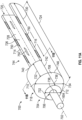
- FIG. 10 is a perspective view of a tissue resecting handset 1600 that comprises a reusable portion 1602 and a disposable portion 700 in accordance with yet still other embodiments.
- the handset 1600 may be coupled to a plurality of peripheral devices including a power source, fluid source, filtration device, and pump, as discussed below in detail in FIGS. 11-14 .
- the handset 1600 is configured so that the reusable portion 1602 and the disposable portion 700 are engaged along a plurality of locking features on each portion and disengaged after use, at which point the disposable portion is disposed and the reusable portion is either cleaned but not sterilized, or cleaned and sterilized, depending upon the embodiment and configuration of the handset 1600.
- the handset may comprise an elongated shaft 1604 having an aperture 1607 at a distal end 1609 of the elongated shaft 1604.
- a cutting element 1606 is disposed within the elongated shaft 1604 in operational relationship to the aperture 1607.
- FIG. 11A is a partial perspective view of a disposable portion 700 of a handset.
- the disposable portion 700 comprises a central axis 702, a tapered distal end of the handle portion 704 and a proximal end 720.
- the disposable portion 700 further comprises an overall length 724 comprising a first portion 718 and a second portion 744, the first portion 718 comprising a length 742, the first portion 718 may also be referred to as the hub section 718 since a rotational hub is disposed in the hub section (the rotational hub is illustrated and discussed below in at least FIGS. 14A and 14B ).
- the distal end of the hub section 718 comprises an instrument engagement feature 706 where an elongated shaft comprising a cutting element may be disposed (only a portion of the elongated shaft is visible).
- the tapered distal end of the handle portion 704 is defined by a first elliptical feature 712 comprising a largest outer diameter 736 and a second elliptical feature 746 comprising a largest outer diameter 738, a length 742, and a smooth transition surface 708 between the first 712 and the second elliptical feature 746 circumferentially around the hub section 718.
- the distal end of the hub section 718 may be defined in various configurations and geometries.
- the distal end of the hub section 718 may be further defined by an apex 710 and a bottom smoothly curved surface 734, both along the second elliptical feature 746, and an apex 732, and an elongated shaft 1604 that is in communication with a fluid path within the hub portion 718, not shown here.
- the hub section 718 comprises a proximal portion length 722 and a proximal end 740 configured to mate with a reusable portion (not pictured) via a plurality of locking features.
- the second portion 744 comprises a length 730, a first surface 714, and a second surface 716, and may also be referred to as the mating section 744.
- the first 714 and second 716 surfaces extend from the proximal end 740 of the hub section 718 to the proximal end 720 of the disposable portion 700 parallel to the central axis 702. While the mating section 744 is illustrated here in one embodiment, in alternate embodiments, it may be different in length or otherwise vary as appropriate for the design of the disposable portion 700.
- a channel 728 extends for at least a portion of the mating section 744.
- the mating section 744 may comprise a plurality of locking features 750, which may be formed and/or disposed on any or all of the first surface 714, the second surface 716, and/or an interior surface 726 of the channel 728.
- the plurality of locking features 750 may be disposed in various patterns, configurations using varying geometries and styles.
- the plurality of locking features 750 may comprise guide tracks (as shown in FIG. 10 ), rails, press-fit features, snap-fit features, pins, fasteners, frictional engagement, threads, or combinations thereof as appropriate.
- the elongated shaft 1604 may extend beyond that shown in FIG.
- the proximal end 720 may be configured to fluidly couple at least to a waste, collection, filtration, or other apparatus configured to receive at least one of fluid and/or tissue removed from the organ.
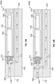
- FIG. 11B is a cross sectional view 800A taken along line 11B-11B in FIG. 11A .
- FIG. 11B illustrates the central axis 702, fluid path 802 through the hub section.
- the fluid path 802 may comprise a consistent diameter throughout, or may be tapered, depending upon the embodiment.
- FIG. 11B also illustrates a driver connector 812, in some embodiment in the form of a counter-bore into the rotating hub 814into which a hub drive shaft of the reusable portion (discussed below) telescopes as part of being detachably connected.
- the rotating hub 814 which may be fluidly isolated from the reusable portion by a seal 816, which may comprise an o-ring, a shaft seal, or a spring seal.
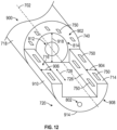
- FIG. 12 is a perspective view 900 of the disposable portion 700, illustrated from the proximal end 720 looking towards the distal end in order to illustrate the locking and other mating features.
- the view 900 illustrates the central axis 702, and a rotating hub 814 is disposed in the hub portion 718 exposed to the mating section.
- the rotating hub 814 defines the driver connector 812, in some embodiment in the form of a counter-bore into the rotating hub 814.
- Also illustrated in the view 900 are a third flat surface 902 located on the proximal end 740 of the hub section 718, and the third flat surface 902 may comprise a plurality of locking features 750 as discussed above.
- the seal 816 is not illustrated in this view, as the rotating hub 814 is only partially exposed in this embodiment.
- FIGS. 13A and13B are schematic illustrations of a perspective view 1700A ( FIG. 13A ) and an end elevation view 1700B ( FIG. 13B ) of a reusable portion of a handset.
- FIG. 13A illustrates the perspective view 1700A of the reusable portion, which comprises an outer casing defined by a smoothly curved upper surface 1722, a first side 1718 and a second side 1726 that are parallel to the central axis 1706.
- the smoothly curved upper surface 1722 joins the first side 1718 and the second side 1726 by way of shelves 1720 (the shelves 1720 are perpendicular to their respective sides 1718 and 1726).
- the example reusable portion also comprises a bottom feature that may be a flat bottom feature 1714 perpendicular to the sides 1718 and 1726.
- the outer casing extends along a length from a distal end 1710 to a proximal end 1708 along a central axis 1706.
- the reusable portion 1700A comprises a motor and a heat sink 1702 as well as a plurality of electronic components 1704 and at least one connection port 1724 that may be used to supply power to the reusable portion and/or to connect to peripheral devices.
- the motor 1702 and the plurality of electronic components 1704 may be in various configurations disposed adjacent to one another or spaced a predetermined distance from each other, depending upon the embodiment.
- the motor 1702 may comprise a hub drive shaft 1712 that extends from the motor 1702 at the distal end 1710, parallel to the central axis 1706.
- the hub drive shaft 1712 couples to the rotating hub of the disposable portion, as illustrated in FIGS. 14A and 14B .
- the reusable portion shown in view 1700A may further comprise a plurality of locking features 1716 formed on at least one of the sides 1726 and 1718.
- the shelves 1720 are parallel to both the central axis 1706 and perpendicular to the sides 1726 and 1718, and may comprise locking features (which are not visible in the view of FIG 13A ).
- the locking features 1716 may comprise tabs (such as shown in FIG.
- FIG. 13B is the end-elevation view 1700B of the distal end 1710 of 1700A from FIG. 13A , and illustrates the outer casing's curved top surface 1722, flat bottom 1714, the hub drive shaft 1712 of the motor (not pictured in FIG. 13B ), the first and second sides 1718 and 1726 where the locking features 1716 may be located.
- FIGS. 14A-14B illustrate different schematic cross sectional views of the disposable portion of a handset detachably coupled to a reusable portion of the handset according to embodiments of the present disclosure.
- FIG. 14A is an illustration of a partial cross section 1400A of an embodiment of the disposable portion of a handset detachably coupled to a reusable portion of the handset.
- the cross section 1400A illustrates a disposable portion 1402 and a reusable portion 1404.
- the disposable portion 1402 comprises the fluid path 1412 which begins in an instrument, partially shown in FIG. 14A as elongated shaft 1604 (as also shown in FIG. 10 ), and, as discussed above, has an inflow location 1422 and an outflow location 1424.
- the fluid path 1412 extends into and through the rotating hub 814 and continues through the disposable portion 1402.
- the fluid path 1412 in FIG. 14B extends into the rotating hub to enable the blade drive shaft (not specifically shown) to access the fluid path, and the rotating hub is designed and constructed to enable the fluid and/or resected tissue to travel through the hub.
- the seal 816 may comprise an O-ring or another type of seal, which may be a flexible or a rigid seal, or comprise multiple components, may be disposed on an outside surface of the rotating hub 814, and particularly on the proximal side of the rotating hub 814.
- the seal 816 fluidly isolates the rotating hub 814 (and the disposable portion 1402) from the motor 1406, electronics 1408, and other components in the reusable portion 1404, which may also comprise at least one connection port 1724 for power and other connections.
- the reusable portion 1404 may be detachably coupled to the detachable portion 1402 by multiple means including the locking features 750 discussed above, which are engaged but not illustrated in this view, as well as through the coupling of the hub drive shaft 1712 extending from the motor 1406 that mates with a drive connector defined in the rotating hub 814 as illustrated.
- FIG. 14B is an illustration of a partial cross section 1400B of an embodiment of the disposable portion of a handset detachably coupled to a reusable portion of the handset.
- the cross section 1400B illustrates a disposable portion 1402 and a reusable portion 1404.
- the disposable portion 1402 comprises the fluid path 1412 which begins in an instrument, partially shown in FIG 14A as the elongated shaft 1604, and, as discussed above, has an inflow location 1422 and an outflow location 1424.
- the fluid path 1412 extends to but not through the rotating hub 814, and fluid path also extends through the disposable portion 1402.
- the fluid path 1412 in FIG. 14B extends to the rotating hub to enable the blade drive shaft (not specifically shown) to access the fluid path.
- the blade drive shaft not specifically shown
- seal 816 which may comprise an O-ring or another type of seal, which may be a flexible or a rigid seal, or comprise multiple components, may be in operational relationship to the rotating hub 814 and fluidly isolates the rotating hub 814 (and the disposable portion 1402) from the motor 1406, electronics 1408, and other components in the reusable portion 1404, which may also comprise at least one connection port 1724 for power and other connections.
- the reusable portion 1404 may be detachably coupled to the detachable portion 1402 by multiple means including the locking features 750 discussed above, which are engaged but not illustrated in this view, as well as through the coupling of the hub drive shaft 1712 from the motor 1406 that mates with the rotating hub 814 as illustrated.
- FIG. 15 illustrates a system diagram for a tissue resecting system 1500 according to certain embodiments of the present disclosure.
- the system 1500 comprises a foot switch 1502 coupled to a power source 1504 that is also coupled to a pump/suction device 1506, a filtration device 1508, and a fluid source 1512.
- the power source 1504 is also coupled to the handset 1510 that comprises the disposable portion discussed above and, in some cases, an endoscope 1514.
- the handset 1510 may also be coupled to the filtration device 1508 by way of tubing, and the filtration device 1508 may be connected to a sample collection station which the handset 1510 may in some cases directly access without filtration using 1508.
- the power source 1504 may supply power to the handset 1510 for at least the motor to activate the cutting device, which may also be coupled to the pump/suction device 1506 to provide suction through the fluid channel while cutting tissue and removing fluid.
- the handset 1510 may be connected to one or both of the filtration 1508 and sample collection 1516 devices and may use one or both depending upon the embodiment (as indicated by the arrows) in order to collect tissue samples and recirculate the fluid as illustrated, where the fluid is removed by the handset 1510, sent through the filtration device 1508, where the tissue is separated out, and then the fluid may be returned (recirculated) to the body, for example, by way of the endoscope 1514.
- the disposable portion of the handset 1510 may be disengaged from the reusable portion and disposed of, while the reusable portion is wiped manually or otherwise cleaned, in some embodiments the reusable portion is not sterilized, for example, using an autoclave, and in other embodiments sterilization may be employed.
- the endoscope 1514 may be in fluid communication with the sample collection device 1516, and in other embodiments (not illustrated here), the endoscope may be connected to the filtration device 1508 directly, e.g., not through the handset portion, in addition to or instead of the connection to the sample collection device 1516.
- tissue resecting system comprising: a resector including a handset and a cutting element that extends from the handset to cut tissue from an organ; and a footswitch coupled to the resector, the footswitch being selectively operated to activate the cutting element, and the footswitch including one or more control elements that control the operation of the cutting element according to selected parameters.
- the tissue resecting system wherein the footswitch includes a motor that is coupled to and drives the cutting element via a flexible drive shaft, the one or more control elements controlling the motor to drive the cutting element.
- the tissue resecting system further comprising wherein the handset includes a pump, a first fluid line, and a second fluid line, the pump drawing fluid, with suction, from the organ through the first fluid line and pushing the fluid into the second fluid line for further processing, and the fluid drawn from the organ by the pump carries tissue cut from the organ by the cutting element, the footswitch being selectively operated to activate the pump, the one or more control elements controlling the operation of the pump according to the selected parameters.
- the handset includes a filtration system that filters the fluid from the organ, the pump pushing the fluid through the filtration system and into the second fluid line, the second fluid line delivering the filtered fluid to the organ.
- the tissue resecting system further comprising an endoscope that is configured to be inserted into the organ and to guide the cutting element into the organ, the endoscope including a passageway that is configured to extend into the organ, the passageway being coupled to the second fluid line, the passageway delivering the filtered fluid to the organ.
- the footswitch includes a motor that is coupled to a gear box and clutch component via a flexible drive shaft, the gear box and clutch component driving the cutting element and the pump, the one or more control elements controlling the motor to drive the cutting element and the pump according to the selected parameters.
- a pump may be disposed externally from the handset, wherein the handset include a first fluid line and a second fluid line, the pump drawing fluid, with suction, from the organ through the first fluid line and pushing the fluid into the second fluid line for further processing, the fluid drawn from the organ by the pump carrying tissue cut from the organ by the cutting element, the footswitch being selectively operated to activate the pump, the one or more control elements controlling the operation of the pump according to the selected parameters, and in some embodiments, the pump is housed in the footswitch.
- the footswitch includes a motor that is coupled to a gear box and clutch component via a flexible drive shaft, the gear box and clutch component driving the cutting element and the pump, the one or more control elements controlling the motor to drive the cutting element and the pump according to selected parameters.
- filtration system may be disposed externally from the handset, the filtration system filtering the fluid from the organ, the pump pushing the fluid through the filtration system and into the second fluid line, the second fluid line delivering the filtered fluid to the organ, and in some embodiments, the filtration system is housed in the footswitch.
- the footswitch includes a user interface, the user interface including a display and user inputs, the user inputs receiving the selected parameters from a user.
- a first pump is disposed externally from the handset and a second pump disposed externally from the handset, wherein the handset include a first fluid line and a second fluid line, the first pump drawing fluid, with suction, from the organ through the first fluid line and pushing the fluid towards the second pump, the second pump drawing the fluid from the first pump and pushing the fluid into the second fluid line.
- the fluid is drawn from the organ by the first pump carrying tissue cut from the organ by the cutting element, the footswitch is selectively operated to activate the first pump and the second pump, the one or more control elements controlling the operation of the first and the second pumps according to the selected parameters.
- the first and the second pumps are housed in the footswitch which further includes a motor that is coupled to a gear box and clutch component via a flexible drive shaft, the gear box and clutch component driving the cutting element and the first and the second pumps, the one or more control elements controlling the motor to drive the cutting element and the first and the second pumps according to selected parameters.
- a filtration system is disposed externally from the handset and operatively between the first and the second pumps such that the filtration system is configured to filter the fluid sucked from the organ by the first pump, the first pump pushing the fluid through the filtration system and the second pump pulling the filter fluid from the filtration system and pushing the filter fluid into the second fluid line, the second fluid line delivering the filtered fluid to the organ.
- a tissue resecting system comprising: a handset including: a disposable portion including a pump, a first fluid line, and a second fluid line, the pump drawing fluid, with suction, from an organ through the first fluid line and moving the fluid into the second fluid line for further processing; and a reusable portion that is detachably coupled to the disposable portion to define a single housing for the handset, the reusable portion including one or more drive components that drive the pump; and a cutting element that extends from the handset to cut tissue from the organ, wherein the fluid drawn from the organ by the pump carries tissue cut from the organ by the cutting element.
- the disposable portion includes a filtration system that filters the fluid from the organ, the pump moving the fluid through the filtration system and into the second fluid line, the second fluid line delivering the filtered fluid to the organ.
- the second fluid line delivers the fluid to an external receptacle.
- the one or more drive components in the reusable portion include a motor and drive the cutting element.
- the one or more drive components drive the shaft to cause a cutting action with the cutting element and the one or more drive components may include a gearbox and clutch component that divides drive between the pump and the cutting element.
- the system further comprises an endoscope that is configured to be inserted into the organ and to guide the cutting element into the organ, the endoscope including an inflow passageway that is configured to extend into the organ, the passageway being coupled to the second fluid line, the passageway delivering the filtered fluid to the organ.
- the reusable portion includes a battery that powers the motor and a cable that electrically couples the motor to an external power source.
- the handset includes a control element that is configured to be selectively operated by a user to cause the one or more drive components to engage the cutting element to cause a cutting action, while the one or more drive components continue to drive the pump.
- the system further comprises a shaft that extends from the handset and into the endoscope, the cutting element being disposed at an end of the shaft, which comprises an outflow passageway that extends from an opening at the cutting element and into the handset, the outflow passageway being coupled to the first fluid line, the pump drawing the fluid from the organ through the opening and into the outflow passageway via the first fluid line.
- a tissue resecting system comprising: a handset including a disposable housing including a pump, a first fluid line, a second fluid line, and one or more drive components that drive the pump, the pump drawing fluid, with suction, from an organ through the first fluid line and moving the fluid into the second fluid line for further processing; and a cutting element that extends from the handset to cut tissue from the organ, wherein the fluid drawn from the organ by the pump carries tissue cut from the organ by the cutting element.
- the housing includes a filtration system that filters the fluid from the organ, the pump pumping the fluid through the filtration system and into the second fluid line, the second fluid line delivering the filtered fluid to the organ.
- the system may further comprise an endoscope that is configured to be inserted into the organ and to guide the cutting element into the organ, the endoscope including an inflow passageway that is configured to extend into the organ, the passageway being coupled to the second fluid line, the passageway delivering the filtered fluid to the organ.
- the housing comprises a plurality of sections and includes a disposable battery that powers the motor, and the one or more drive components drive the cutting element.
- the housing includes a first section and a second section, the first section including the pump, the first fluid line, and the second fluid line, and the second section including the one or more drive components.
- the one or more drive components include a gear box and clutch component that divides drive between the pump and the cutting element
- the handset includes a control element that is configured to be selectively operated by a user to cause the one or more drive components to engage the cutting element to cause a cutting action, while the one or more drive components continue to drive the pump.
- the second fluid line delivers the fluid to an external receptacle.
- the system further comprising an endoscope that is configured to be inserted into the organ and to guide the cutting element into the organ and a shaft that extends from the handset and into the endoscope, the cutting element being disposed at an end of the shaft, wherein the shaft includes an outflow passageway that extends from an opening at the cutting element and into the housing, the outflow passageway being coupled to the first fluid line, the pump drawing the fluid from the organ through the opening and into the outflow passageway via the first fluid line, wherein the one or more drive components drive the shaft to cause a cutting action with the cutting element.
- the implementations provide tissue-resecting systems that include footswitches that compactly integrate components for extracting fluid/tissue from an organ.
- the footswitches include one or more control elements and a motor to drive the pump and the cutting element of a resector according to selected parameters.
- the footswitches include the pump and the filtration system in addition to the one or more control elements and the motor.
- the footswitches may include a disposable portion that allows components that contact the fluid/tissue (e.g., the pump, the filtration system, etc.) to be easily disposed, thereby promoting hygienic use of the tissue resecting system.
- the footswitches may include a reusable portion that allows other components (e.g., drive components like the motor
Landscapes
- Health & Medical Sciences (AREA)
- Surgery (AREA)
- Life Sciences & Earth Sciences (AREA)
- Biomedical Technology (AREA)
- Nuclear Medicine, Radiotherapy & Molecular Imaging (AREA)
- Engineering & Computer Science (AREA)
- Orthopedic Medicine & Surgery (AREA)
- Heart & Thoracic Surgery (AREA)
- Medical Informatics (AREA)
- Molecular Biology (AREA)
- Animal Behavior & Ethology (AREA)
- General Health & Medical Sciences (AREA)
- Public Health (AREA)
- Veterinary Medicine (AREA)
- Surgical Instruments (AREA)
Claims (15)
- Composant de combiné jetable (310, 310A) comprenant :une partie de poignée qui définit une section de moyeu et une section d'accouplement, la poignée définit un chemin fluidique qui s'étend à travers la section de moyeu et la section d'accouplement ;un arbre allongé (302) accouplé à la section de moyeu de la partie de poignée, l'arbre allongé (302) définit un canal d'écoulement interne (303) accouplé de manière fluidique au chemin fluidique, et un axe central ;une ouverture à travers une extrémité distale de l'arbre allongé (302) ;une lame de coupe à l'intérieur de l'arbre allongé (302) et en relation opérationnelle avec l'ouverture ;un moyeu rotatif disposé à l'intérieur de la section de moyeu et en relation opérationnelle avec une partie du chemin fluidique à l'intérieur de la section de moyeu, le moyeu rotatif définit un connecteur d'entraînement exposé au niveau d'une transition entre la section de moyeu et la section d'accouplement ;un arbre d'entraînement qui accouple mécaniquement la lame de coupe au moyeu rotatif, l'arbre d'entraînement étant disposé à l'intérieur du canal d'écoulement interne (303) de l'arbre allongé et également disposé dans la partie du chemin fluidique dans la section de moyeu ; etun joint d'étanchéité en relation opérationnelle avec le moyeu rotatif et la section de moyeu, le joint d'étanchéité isole fluidiquement le canal fluidique du connecteur d'entraînement exposé au niveau de la transition entre la section de moyeu et la section d'accouplement.
- Combiné jetable (310, 310A) selon la revendication 1 dans lequel la section d'accouplement de la poignée comprend en outre un creux défini par une première paroi sur un premier côté de la section d'accouplement, et une seconde paroi sur un second côté de la section d'accouplement opposée à la première paroi, le creux s'étend du connecteur d'entraînement à une extrémité proximale de la poignée.
- Combiné jetable (310, 310A) selon la revendication 2 comprend en outre :une première voie de guidage disposée sur la première paroi à l'intérieur du creux, au moins une partie de la première voie de guidage définit un premier canal parallèle à l'axe central ; etune deuxième voie de guidage disposée sur la seconde paroi à l'intérieur du creux, au moins une partie de la deuxième voie de guidage définit un deuxième canal parallèle à l'axe central.
- Combiné jetable (310, 310A) selon la revendication 3 :la première voie de guidage définit en outre une première ouverture sur une partie supérieure de la première paroi ; etle deuxième canal définit en outre une seconde ouverture sur une partie supérieure de la seconde paroi opposée à la première paroi.
- Combiné jetable (310, 310A) selon la revendication 2 comprend en outre :une première voie de guidage disposée sur la première paroi à l'intérieur du creux, au moins une partie de la première voie de guidage définit un premier canal parallèle à l'axe central ; etune deuxième voie de guidage disposée sur la seconde paroi à l'intérieur du creux, à l'opposé de la première voie de guidage, au moins une partie de la deuxième voie de guidage définit un deuxième canal parallèle à l'axe central ;une troisième voie de guidage disposée sur la première paroi à l'intérieur du creux, la troisième voie de guidage étant proximale à la première voie de guidage, et au moins une partie de la troisième voie de guidage définit un troisième canal aligné avec le premier canal ; etune quatrième voie de guidage disposée sur la seconde paroi à l'intérieur du creux, à l'opposé de la troisième voie de guidage, au moins une partie de la quatrième voie de guidage définit un quatrième canal aligné avec le deuxième canal.
- Combiné jetable (310, 310A) selon la revendication 1 dans lequel le connecteur d'entraînement comprend en outre une caractéristique du moyeu rotatif qui définit une profondeur dans le moyeu rotatif, et au moins une partie de la profondeur de la caractéristique alignée avec l'axe central.
- Système de résection tissulaire (10), comprenant :le composant de combiné jetable (310, 310A) selon la revendication 1, dans lequel l'arbre d'entraînement est un arbre d'entraînement à lame ; etune partie réutilisable (310B) comprenant :un boîtier extérieur accouplé de manière amovible à la section d'accouplement de la partie jetable, le boîtier extérieur définit un volume interne ;une pluralité de composants d'entraînement (320) disposés au moins partiellement à l'intérieur du volume interne de la partie réutilisable (310B), et dans lequel la pluralité de composants d'entraînement (320) sont configurés pour actionner le moyeu rotatif lorsque le dispositif de résection tissulaire est en cours d'utilisation ;une source d'énergie couplée à la partie réutilisable (310B).
- Système de résection tissulaire (10) selon la revendication 7, dans lequel la pluralité de composants d'entraînement (320) comprend un moteur électrique (320) qui définit un arbre d'entraînement de moyeu, l'arbre d'entraînement de moyeu fait saillie à travers le boîtier extérieur de la partie réutilisable (310B), de préférence dans lequel la partie réutilisable (310B) comprend en outre un dissipateur de chaleur en relation opérationnelle avec le moteur électrique.
- Système de résection tissulaire (10) selon la revendication 7, dans lequel le canal d'écoulement (303) est isolé fluidiquement de la partie réutilisable (310B).
- Système de résection tissulaire (10) selon la revendication 7, comprenant en outre :un endoscope qui est conçu pour être inséré dans un organe, l'endoscope comportant un canal de travail qui est conçu pour s'étendre dans l'organe, dans lequel le canal de travail comprenant un passage d'entrée ; etl'arbre allongé de la partie jetable télescopée à travers le canal de travail, comprenant de préférence en outre :une pompe (316) accouplée fluidiquement au canal d'écoulement (303) et au chemin fluidique, et la pompe étant également accouplée fluidiquement au passage d'entrée de l'endoscope ;un filtre (318) accouplé fluidiquement entre le canal d'écoulement (303) et le passage d'entrée, le filtre étant conçu pour éliminer les tissus du fluide ; etdans lequel la pompe est configurée pour aspirer le fluide et les tissus à travers le canal d'écoulement (303) et le chemin fluidique, et pour renvoyer au moins une partie du fluide dans le passage d'entrée après avoir traversé le filtre.
- Système de résection tissulaire (10) selon l'une quelconque des revendications précédentes 7-10, comprenant en outre un câble qui couple électriquement la pluralité de composants d'entraînement (320) à la source d'énergie.
- Système de résection tissulaire (10) selon l'une quelconque des revendications précédentes 7-11, dans lequel la partie réutilisable (310B) comprend en outre une batterie (422) qui alimente la pluralité de composants d'entraînement (320).
- Système de résection tissulaire (10) selon l'une quelconque des revendications précédentes 7-12, comprenant en outre un interrupteur de commande (321) qui, lorsqu'il est activé, vient en prise avec la pluralité de composants d'entraînement (320) pour faire fonctionner la lame de coupe.
- Système de résection tissulaire (10) selon l'une quelconque des revendications précédentes 7-13, dans lequel l'extrémité proximale de la partie jetable (310, 310A) est accouplée à au moins l'un parmi un système de filtration, un système de collecte d'échantillons, ou un autre réceptacle utilisé pour un traitement ultérieur.
- Système de résection tissulaire (10) selon l'une quelconque des revendications précédentes 7-14, dans lequel la partie réutilisable (310B) est accouplée de manière amovible à la partie jetable (310, 310A) par l'intermédiaire d'une pluralité de caractéristiques de verrouillage formées sur au moins l'une parmi une partie réutilisable (310B) et la partie jetable, de préférence dans lequel la pluralité de caractéristiques de verrouillage sont au moins l'une choisie dans le groupe constitué : d'une mise en prise filetée ; d'un bouton-pression ; d'une mise en prise par friction ; d'épingles ; de fixations ; et des combinaisons de ceux-ci.
Applications Claiming Priority (3)
| Application Number | Priority Date | Filing Date | Title |
|---|---|---|---|
| US201462092698P | 2014-12-16 | 2014-12-16 | |
| US201462092686P | 2014-12-16 | 2014-12-16 | |
| PCT/US2015/066111 WO2016100522A1 (fr) | 2014-12-16 | 2015-12-16 | Dispositif chirurgical avec système d'extraction tissulaire incorporé |
Publications (2)
| Publication Number | Publication Date |
|---|---|
| EP3232955A1 EP3232955A1 (fr) | 2017-10-25 |
| EP3232955B1 true EP3232955B1 (fr) | 2024-09-25 |
Family
ID=55272576
Family Applications (1)
| Application Number | Title | Priority Date | Filing Date |
|---|---|---|---|
| EP15830921.1A Active EP3232955B1 (fr) | 2014-12-16 | 2015-12-16 | Dispositif chirurgical avec système d'extraction tissulaire incorporé |
Country Status (6)
| Country | Link |
|---|---|
| US (2) | US10631889B2 (fr) |
| EP (1) | EP3232955B1 (fr) |
| CN (1) | CN107106201B (fr) |
| AU (2) | AU2015364676B2 (fr) |
| CA (1) | CA2971004A1 (fr) |
| WO (1) | WO2016100522A1 (fr) |
Families Citing this family (39)
| Publication number | Priority date | Publication date | Assignee | Title |
|---|---|---|---|---|
| CA2971004A1 (fr) | 2014-12-16 | 2016-06-23 | Covidien Lp | Dispositif chirurgical avec systeme d'extraction tissulaire incorpore |
| TWI611019B (zh) * | 2017-02-13 | 2018-01-11 | Scl Biotech Ltd | 組織細碎裝置及具有組織細碎裝置的設備 |
| WO2019038773A1 (fr) * | 2017-08-25 | 2019-02-28 | Mdsg Innovation Ltd. | Dispositif d'extraction de sonde cardiaque |
| EP3742989B1 (fr) * | 2018-01-26 | 2022-12-14 | Smith & Nephew, Inc. | Dispositif de collecte et d'administration de tissu |
| US10869684B2 (en) * | 2018-02-13 | 2020-12-22 | Covidien Lp | Powered tissue resecting device |
| EP3817673B1 (fr) * | 2018-08-07 | 2024-11-20 | Cardio Flow, Inc. | Dispositifs d'athérectomie |
| US11471206B2 (en) | 2018-09-07 | 2022-10-18 | Cilag Gmbh International | Method for controlling a modular energy system user interface |
| US11804679B2 (en) | 2018-09-07 | 2023-10-31 | Cilag Gmbh International | Flexible hand-switch circuit |
| US12035956B2 (en) | 2018-09-07 | 2024-07-16 | Cilag Gmbh International | Instrument tracking arrangement based on real time clock information |
| US11923084B2 (en) | 2018-09-07 | 2024-03-05 | Cilag Gmbh International | First and second communication protocol arrangement for driving primary and secondary devices through a single port |
| US12144136B2 (en) | 2018-09-07 | 2024-11-12 | Cilag Gmbh International | Modular surgical energy system with module positional awareness with digital logic |
| DE102018133504A1 (de) * | 2018-12-21 | 2020-06-25 | Aesculap Ag | Integrierte Leistungseinheit IPU |
| DE102019101308A1 (de) * | 2019-01-18 | 2020-07-23 | Aesculap Ag | Integrierte Leistungseinheit IPU |
| EP3930601A4 (fr) * | 2019-02-27 | 2022-11-23 | MDSG Innovation Ltd. | Dispositif d'explantation de conducteur cardiaque |
| US11743665B2 (en) | 2019-03-29 | 2023-08-29 | Cilag Gmbh International | Modular surgical energy system with module positional awareness sensing with time counter |
| US11602589B2 (en) * | 2019-05-21 | 2023-03-14 | Covidien Lp | Peristaltic pumps with selective activation of multiple fluid lines and fluid management systems including the same |
| USD939545S1 (en) | 2019-09-05 | 2021-12-28 | Cilag Gmbh International | Display panel or portion thereof with graphical user interface for energy module |
| US20210186590A1 (en) * | 2019-12-21 | 2021-06-24 | Covidien Lp | Motor-driven, multi-output surgical pump assembly and surgical generator incorporating the same |
| WO2021199212A1 (fr) * | 2020-03-30 | 2021-10-07 | テルモ株式会社 | Dispositif médical |
| WO2021199211A1 (fr) * | 2020-03-30 | 2021-10-07 | テルモ株式会社 | Dispositif médical |
| US11957373B2 (en) | 2020-05-12 | 2024-04-16 | Smith & Nephew, Inc. | Systems and methods of determining orientation of cutting windows of a mechanical resection instrument |
| EP4117536A4 (fr) * | 2020-05-20 | 2024-03-20 | Meditrina, Inc. | Systèmes et procédés de gestion des liquides |
| US11571233B2 (en) | 2020-11-19 | 2023-02-07 | Covidien Lp | Tissue removal handpiece with integrated suction |
| US11963727B2 (en) | 2021-03-30 | 2024-04-23 | Cilag Gmbh International | Method for system architecture for modular energy system |
| US12040749B2 (en) | 2021-03-30 | 2024-07-16 | Cilag Gmbh International | Modular energy system with dual amplifiers and techniques for updating parameters thereof |
| US11857252B2 (en) | 2021-03-30 | 2024-01-02 | Cilag Gmbh International | Bezel with light blocking features for modular energy system |
| US12369994B2 (en) | 2021-03-30 | 2025-07-29 | Cilag Gmbh International | Modular energy system with multi-energy port splitter for multiple energy devices |
| US12228987B2 (en) | 2021-03-30 | 2025-02-18 | Cilag Gmbh International | Method for energy delivery for modular energy system |
| US11968776B2 (en) | 2021-03-30 | 2024-04-23 | Cilag Gmbh International | Method for mechanical packaging for modular energy system |
| US12235697B2 (en) | 2021-03-30 | 2025-02-25 | Cilag Gmbh International | Backplane connector attachment mechanism for modular energy system |
| US12004824B2 (en) | 2021-03-30 | 2024-06-11 | Cilag Gmbh International | Architecture for modular energy system |
| US11950860B2 (en) | 2021-03-30 | 2024-04-09 | Cilag Gmbh International | User interface mitigation techniques for modular energy systems |
| US11980411B2 (en) | 2021-03-30 | 2024-05-14 | Cilag Gmbh International | Header for modular energy system |
| US11978554B2 (en) | 2021-03-30 | 2024-05-07 | Cilag Gmbh International | Radio frequency identification token for wireless surgical instruments |
| US12354186B2 (en) | 2021-04-14 | 2025-07-08 | Cilag Gmbh International | Customization of overlaid data and configuration |
| CN115405601B (zh) * | 2022-07-26 | 2026-01-06 | 免麻科技(苏州)有限公司 | 一种带二次紧固的纹绣仪 |
| US20240299062A1 (en) * | 2021-07-27 | 2024-09-12 | Mdsg Innovation Ltd. | Cardiac lead extraction device |
| ES2938393B2 (es) * | 2022-04-11 | 2023-11-17 | Pacheco Luis Alonso | Dispositivo accionador portable de un instrumento médico para la toma de biopsias y extracción de tejido por histeroscopia |
| US12079460B2 (en) | 2022-06-28 | 2024-09-03 | Cilag Gmbh International | Profiles for modular energy system |
Family Cites Families (246)
| Publication number | Priority date | Publication date | Assignee | Title |
|---|---|---|---|---|
| US1585934A (en) | 1923-12-29 | 1926-05-25 | Radium Emanation Corp | Diagnostic needle |
| US1831786A (en) | 1926-04-20 | 1931-11-10 | California Packing Corp | Fruit peeling apparatus |
| US1666332A (en) | 1927-05-23 | 1928-04-17 | Edwin W Hirsch | Bladder-pressure-testing apparatus |
| US2708437A (en) | 1952-03-31 | 1955-05-17 | Elizabeth Painter Hutchins | Surgical instrument |
| US3297022A (en) | 1963-09-27 | 1967-01-10 | American Cystoscope Makers Inc | Endoscope |
| GB1288091A (fr) | 1969-01-03 | 1972-09-06 | ||
| DE7107645U (de) | 1971-03-02 | 1971-05-27 | Storz K | Endoskop insbesondere cystoskop |
| US3734099A (en) | 1971-04-07 | 1973-05-22 | H Bender | Powered surgical cutter |
| US3812855A (en) | 1971-12-15 | 1974-05-28 | Surgical Design Corp | System for controlling fluid and suction pressure |
| US3945375A (en) | 1972-04-04 | 1976-03-23 | Surgical Design Corporation | Rotatable surgical instrument |
| US3835842A (en) | 1972-07-03 | 1974-09-17 | J Iglesias | Endoscope with continuous irrigation |
| US3850162A (en) | 1972-07-03 | 1974-11-26 | J Iglesias | Endoscope with continuous irrigation |
| US3996921A (en) | 1975-04-17 | 1976-12-14 | Pharmacia Inc. | Method and apparatus for endoscopy |
| US4011869A (en) | 1975-08-01 | 1977-03-15 | David Kopf Instruments | Tubular cutting instrument |
| US3995619A (en) | 1975-10-14 | 1976-12-07 | Glatzer Stephen G | Combination subcutaneous suture remover, biopsy sampler and syringe |
| US3980252A (en) | 1975-10-31 | 1976-09-14 | John T. Hepburn Limited | Wire rope spooling mechanism |
| US4146405A (en) | 1977-01-19 | 1979-03-27 | Henry Timmer | Unitary dishwasher |
| US4108182A (en) | 1977-02-16 | 1978-08-22 | Concept Inc. | Reciprocation vitreous suction cutter head |
| US4198958A (en) | 1977-06-01 | 1980-04-22 | Olympus Optical Co., Ltd. | Flexible cap and instrument seal for a suction control device in an endoscope |
| US4414962A (en) | 1977-06-15 | 1983-11-15 | Carson Robert W | Operating arthroscope |
| US4203444A (en) | 1977-11-07 | 1980-05-20 | Dyonics, Inc. | Surgical instrument suitable for closed surgery such as of the knee |
| FR2415451A1 (fr) | 1978-01-26 | 1979-08-24 | Bernard Parent | Hysteroscope de diagnostic a vision panoramique |
| US4246902A (en) | 1978-03-10 | 1981-01-27 | Miguel Martinez | Surgical cutting instrument |
| US4210146A (en) | 1978-06-01 | 1980-07-01 | Anton Banko | Surgical instrument with flexible blade |
| US4316465A (en) | 1979-03-30 | 1982-02-23 | Dotson Robert S Jun | Ophthalmic handpiece with pneumatically operated cutter |
| US4294234A (en) | 1979-06-22 | 1981-10-13 | Olympus Optical Co., Ltd. | Endoscope |
| US4247180A (en) | 1979-08-06 | 1981-01-27 | Polaroid Corporation | Card motion picture apparatus with adjustable barrel cam |
| US4261346A (en) | 1979-11-23 | 1981-04-14 | Richard Wolf Medical Instruments Corporation | Endoscopes |
| US4369768A (en) | 1980-07-30 | 1983-01-25 | Marko Vukovic | Arthroscope |
| US4493698A (en) | 1980-11-03 | 1985-01-15 | Cooper Medical Devices | Method of performing opthalmic surgery utilizing a linear intra-ocular suction device |
| US4392485A (en) | 1981-02-17 | 1983-07-12 | Richard Wolf Gmbh | Endoscope |
| US4517977A (en) | 1981-07-24 | 1985-05-21 | Unisearch Limited | Co-axial tube surgical infusion/suction cutter tip |
| US4449538A (en) | 1982-01-25 | 1984-05-22 | John Corbitt | Medical-electronic body fluid accounting system |
| DE3364922D1 (en) | 1982-05-28 | 1986-09-04 | Rhp Group Plc | Devices for converting rotary movement into linear movement |
| IL66047A0 (en) | 1982-06-13 | 1982-09-30 | Univ Ben Gurion | Method and device for measuring intrauterine pressure during labour |
| US5421819A (en) | 1992-08-12 | 1995-06-06 | Vidamed, Inc. | Medical probe device |
| US5435805A (en) | 1992-08-12 | 1995-07-25 | Vidamed, Inc. | Medical probe device with optical viewing capability |
| JPS59200644A (ja) | 1983-04-27 | 1984-11-14 | オリンパス光学工業株式会社 | 外科用切除器具 |
| US4606330A (en) | 1983-08-09 | 1986-08-19 | Richard Wolf Gmbh | Device for disintegrating stones in bodily cavities or ducts |
| US4601290A (en) | 1983-10-11 | 1986-07-22 | Cabot Medical Corporation | Surgical instrument for cutting body tissue from a body area having a restricted space |
| EP0153190B1 (fr) | 1984-02-20 | 1989-05-03 | Olympus Optical Co., Ltd. | Instruments endoscopiques pour prélèvement d'ovules |
| JPS60243625A (ja) | 1984-05-18 | 1985-12-03 | Fuji Photo Optical Co Ltd | 内視鏡の接続システム |
| GB2159419B (en) | 1984-05-29 | 1987-09-23 | Wolf Gmbh Richard | Uretero-renoscope |
| DE3443337A1 (de) | 1984-11-28 | 1986-05-28 | Richard Wolf Gmbh, 7134 Knittlingen | Instrument zur untersuchung und behandlung von koerperkanaelen |
| US4567880A (en) | 1984-12-26 | 1986-02-04 | Goodman Tobias M | Endoscopic device with three-way valve |
| US4649919A (en) | 1985-01-23 | 1987-03-17 | Precision Surgical Instruments, Inc. | Surgical instrument |
| US4756309A (en) | 1985-02-14 | 1988-07-12 | Sachse Hans Ernst | Endoscope for removal of tissue |
| US4644952A (en) | 1985-02-19 | 1987-02-24 | Palm Beach Medical Engineering, Inc. | Surgical operating instrument |
| JPS61259637A (ja) | 1985-05-15 | 1986-11-17 | オリンパス光学工業株式会社 | 内視鏡装置 |
| JPS62105698A (ja) | 1985-11-05 | 1987-05-16 | ソニー株式会社 | プリンタ |
| US4950278A (en) | 1986-08-06 | 1990-08-21 | Sachse Hans E | Endoscope for removal of tissue |
| US4749376A (en) | 1986-10-24 | 1988-06-07 | Intravascular Surgical Instruments, Inc. | Reciprocating working head catheter |
| US5312430A (en) | 1986-12-09 | 1994-05-17 | Rosenbluth Robert F | Balloon dilation catheter |
| US4867157A (en) | 1987-08-13 | 1989-09-19 | Baxter Travenol Laboratories, Inc. | Surgical cutting instrument |
| US4850354A (en) | 1987-08-13 | 1989-07-25 | Baxter Travenol Laboratories, Inc. | Surgical cutting instrument |
| US4819635A (en) | 1987-09-18 | 1989-04-11 | Henry Shapiro | Tubular microsurgery cutting apparatus |
| US4844064A (en) | 1987-09-30 | 1989-07-04 | Baxter Travenol Laboratories, Inc. | Surgical cutting instrument with end and side openings |
| US4986827A (en) | 1987-11-05 | 1991-01-22 | Nestle S.A. | Surgical cutting instrument with reciprocating inner cutter |
| FR2625428A1 (fr) | 1988-01-05 | 1989-07-07 | Sinergy Sa | Dispositif de coelioscopie operatoire multifonctionnel permettant d'effectuer differents gestes operatoires avec introduction d'instruments |
| DE3805368C1 (fr) | 1988-02-17 | 1989-08-24 | Peter P. Dipl.-Ing. Wiest | |
| US4955882A (en) | 1988-03-30 | 1990-09-11 | Hakky Said I | Laser resectoscope with mechanical and laser cutting means |
| US5027792A (en) | 1989-03-17 | 1991-07-02 | Percutaneous Technologies, Inc. | Endoscopic revision hip surgery device |
| US5116868A (en) | 1989-05-03 | 1992-05-26 | The Johns Hopkins University | Effective ophthalmic irrigation solution |
| JP2787471B2 (ja) | 1989-07-04 | 1998-08-20 | 旭光学工業株式会社 | 内視鏡用シース装置 |
| US5226910A (en) | 1989-07-05 | 1993-07-13 | Kabushiki Kaisha Topcon | Surgical cutter |
| US5106364A (en) | 1989-07-07 | 1992-04-21 | Kabushiki Kaisha Topcon | Surgical cutter |
| US4998527A (en) | 1989-07-27 | 1991-03-12 | Percutaneous Technologies Inc. | Endoscopic abdominal, urological, and gynecological tissue removing device |
| US5226909A (en) | 1989-09-12 | 1993-07-13 | Devices For Vascular Intervention, Inc. | Atherectomy device having helical blade and blade guide |
| US5112299A (en) | 1989-10-25 | 1992-05-12 | Hall Surgical Division Of Zimmer, Inc. | Arthroscopic surgical apparatus and method |
| US5163433A (en) | 1989-11-01 | 1992-11-17 | Olympus Optical Co., Ltd. | Ultrasound type treatment apparatus |
| US5409013A (en) | 1989-11-06 | 1995-04-25 | Mectra Labs, Inc. | Tissue removal assembly |
| US5037386A (en) | 1989-11-17 | 1991-08-06 | Minnesota Mining And Manufacturing Company | Pressure sensing scope cannula |
| US5176677A (en) | 1989-11-17 | 1993-01-05 | Sonokinetics Group | Endoscopic ultrasonic rotary electro-cauterizing aspirator |
| US4940061A (en) | 1989-11-27 | 1990-07-10 | Ingress Technologies, Inc. | Biopsy instrument |
| US5152744A (en) | 1990-02-07 | 1992-10-06 | Smith & Nephew Dyonics | Surgical instrument |
| US5169397A (en) | 1990-02-08 | 1992-12-08 | Olympus Optical Co., Ltd. | Medical instrument |
| US5007917A (en) | 1990-03-08 | 1991-04-16 | Stryker Corporation | Single blade cutter for arthroscopic surgery |
| EP0448857A1 (fr) | 1990-03-27 | 1991-10-02 | Jong-Khing Huang | Résectoscope rotatif pour prostatectomie |
| US5275609A (en) | 1990-06-22 | 1994-01-04 | Vance Products Incorporated | Surgical cutting instrument |
| US5269785A (en) | 1990-06-28 | 1993-12-14 | Bonutti Peter M | Apparatus and method for tissue removal |
| US5911699A (en) | 1990-07-17 | 1999-06-15 | Aziz Yehia Anis | Removal of tissue |
| US6007513A (en) | 1990-07-17 | 1999-12-28 | Aziz Yehia Anis | Removal of tissue |
| US5158553A (en) | 1990-12-26 | 1992-10-27 | Cardiopulmonics | Rotatably actuated constricting catheter valve |
| US5409453A (en) | 1992-08-12 | 1995-04-25 | Vidamed, Inc. | Steerable medical probe with stylets |
| US5125910A (en) | 1991-02-19 | 1992-06-30 | Dexide, Inc. | Surgical endoscopic suction/irrigation cannula assembly |
| US5490819A (en) | 1991-08-05 | 1996-02-13 | United States Surgical Corporation | Articulating endoscopic surgical apparatus |
| ATE176595T1 (de) | 1991-08-21 | 1999-02-15 | Smith & Nephew Inc | Flüssigkeitenbehandlungssystem |
| US5288290A (en) | 1991-09-25 | 1994-02-22 | Alcon Surgical, Inc. | Multi-ported valve assembly |
| US5195541A (en) | 1991-10-18 | 1993-03-23 | Obenchain Theodore G | Method of performing laparoscopic lumbar discectomy |
| US5449356A (en) | 1991-10-18 | 1995-09-12 | Birtcher Medical Systems, Inc. | Multifunctional probe for minimally invasive surgery |
| US5244459A (en) | 1992-01-28 | 1993-09-14 | Hill Raymond R | Suction irrigator endoscope |
| US5242404A (en) | 1992-02-12 | 1993-09-07 | American Cyanamid Company | Aspiration control system |
| US5254117A (en) | 1992-03-17 | 1993-10-19 | Alton Dean Medical | Multi-functional endoscopic probe apparatus |
| US5350390A (en) | 1992-03-25 | 1994-09-27 | Arieh Sher | Device for removal of intraluminal occlusions |
| US5563481A (en) | 1992-04-13 | 1996-10-08 | Smith & Nephew Endoscopy, Inc. | Brushless motor |
| US5270622A (en) | 1992-04-13 | 1993-12-14 | Smith & Nephew Dyonics, Inc. | Brushless motor control system |
| US5602449A (en) | 1992-04-13 | 1997-02-11 | Smith & Nephew Endoscopy, Inc. | Motor controlled surgical system and method having positional control |
| US5672945A (en) | 1992-04-13 | 1997-09-30 | Smith & Nephew Endoscopy, Inc. | Motor controlled surgical system and method having self clearing motor control |
| US5320091A (en) | 1992-04-27 | 1994-06-14 | Circon Corporation | Continuous flow hysteroscope |
| US5556378A (en) | 1992-06-17 | 1996-09-17 | Storz; Karl | Device for irrigation of body cavities |
| US5312399A (en) | 1992-09-29 | 1994-05-17 | Hakky Said I | Laser resectoscope with mechanical cutting means and laser coagulating means |
| US5304118A (en) | 1992-12-16 | 1994-04-19 | Trese Michael T | Method for performing a vitrectomy on an eye |
| US5347992A (en) | 1993-01-22 | 1994-09-20 | Karl Storz Endoscopy America, Inc. | Single axis three way selector valve for endoscopes |
| US5392765A (en) | 1993-02-11 | 1995-02-28 | Circon Corporation | Continuous flow cystoscope |
| US5403276A (en) | 1993-02-16 | 1995-04-04 | Danek Medical, Inc. | Apparatus for minimally invasive tissue removal |
| CA2161688A1 (fr) | 1993-05-07 | 1994-11-24 | Sdgi Holdings, Inc. | Instrument chirurgical de coupe |
| US5364395A (en) | 1993-05-14 | 1994-11-15 | West Jr Hugh S | Arthroscopic surgical instrument with cauterizing capability |
| AU676057B2 (en) | 1993-06-16 | 1997-02-27 | Baxter Healthcare Sa | Use of and process for the introduction of fibrin sealant into a puncture channel |
| US5395313A (en) | 1993-08-13 | 1995-03-07 | Naves; Neil H. | Reciprocating arthroscopic shaver |
| US5575756A (en) | 1993-08-16 | 1996-11-19 | Olympus Optical Co., Ltd. | Endoscope apparatus |
| US5425376A (en) | 1993-09-08 | 1995-06-20 | Sofamor Danek Properties, Inc. | Method and apparatus for obtaining a biopsy sample |
| US5957832A (en) | 1993-10-08 | 1999-09-28 | Heartport, Inc. | Stereoscopic percutaneous visualization system |
| US5374253A (en) | 1993-10-12 | 1994-12-20 | Burns, Sr.; Charles N. | Medical instrument with automatic shut-off valve |
| US5456689A (en) | 1993-10-13 | 1995-10-10 | Arnold J. Kresch | Method and device for tissue resection |
| US5443476A (en) | 1993-11-12 | 1995-08-22 | Shapiro; Henry | Microsurgical scissor apparatus with rotary cutting blade |
| DE4340056A1 (de) | 1993-11-24 | 1995-06-01 | Delma Elektro Med App | Chirurgische laparoskopische Vorrichtung |
| US5490860A (en) | 1993-12-08 | 1996-02-13 | Sofamor Danek Properties, Inc. | Portable power cutting tool |
| EP0662572B1 (fr) | 1994-01-11 | 1998-04-01 | SAMJOO MACHINERY Co., Ltd. | Dispositif pour convertir un mouvement de rotation en un mouvement linéaire alternatif à vitesse constante et système hydraulique avec un tel dispositif |
| US6359200B1 (en) | 1994-01-13 | 2002-03-19 | Dekalb Genetics Corp. | Inbred corn plant 8M116 |
| US5411513A (en) | 1994-02-24 | 1995-05-02 | Danek Medical, Inc. | Transmission mechanism for a surgical cutting instrument |
| US5483951A (en) | 1994-02-25 | 1996-01-16 | Vision-Sciences, Inc. | Working channels for a disposable sheath for an endoscope |
| US5456673A (en) | 1994-03-23 | 1995-10-10 | Stryker Corporation | Locking cannula for endoscopic surgery |
| US5649547A (en) | 1994-03-24 | 1997-07-22 | Biopsys Medical, Inc. | Methods and devices for automated biopsy and collection of soft tissue |
| US5526822A (en) | 1994-03-24 | 1996-06-18 | Biopsys Medical, Inc. | Method and apparatus for automated biopsy and collection of soft tissue |
| US5709670A (en) | 1994-05-03 | 1998-01-20 | Aquintel, Inc. | Surgical fluid and tissue loss monitor |
| US5492537A (en) | 1994-05-03 | 1996-02-20 | Aquintel, Inc. | Surgical fluid monitor |
| US5702420A (en) | 1994-06-14 | 1997-12-30 | Anthony R. Sterling And Tri-Tech, Inc. | Motorized suction punch forceps |
| US5669921A (en) | 1994-07-19 | 1997-09-23 | Linvatec Corporation | Endoscopic shaver blade window positioning system |
| JP2802244B2 (ja) | 1994-08-29 | 1998-09-24 | オリンパス光学工業株式会社 | 内視鏡用シース |
| US5498258A (en) | 1994-09-13 | 1996-03-12 | Hakky; Said I. | Laser resectoscope with laser induced mechanical cutting means |
| US5569284A (en) | 1994-09-23 | 1996-10-29 | United States Surgical Corporation | Morcellator |
| US6032673A (en) | 1994-10-13 | 2000-03-07 | Femrx, Inc. | Methods and devices for tissue removal |
| AU701424B2 (en) | 1994-10-24 | 1999-01-28 | Smith & Nephew, Inc. | Hollow surgical cutter with apertured flutes |
| DE4440035C2 (de) | 1994-11-10 | 1998-08-06 | Wolf Gmbh Richard | Instrument zum Morcellieren |
| US5603332A (en) | 1995-01-27 | 1997-02-18 | Technological Services, Inc. | Method and apparatus for monitoring the systemic absorption of irrigation fluid during operative hysteroscopy |
| US5601583A (en) | 1995-02-15 | 1997-02-11 | Smith & Nephew Endoscopy Inc. | Surgical instrument |
| US5676497A (en) | 1995-02-27 | 1997-10-14 | Kim; Young S. | Power drill-saw with simultaneous rotation and reciprocation action |
| US5810861A (en) | 1995-03-02 | 1998-09-22 | Gaber; Benny | Uterine tissue collector |
| DE29503478U1 (de) | 1995-03-02 | 1995-04-20 | Richard Wolf Gmbh, 75438 Knittlingen | Endoskop |
| CA2215778A1 (fr) | 1995-03-31 | 1996-10-03 | Boston Scientific Corporation | Preleveur d'echantillons pour biopsie |
| US5873886A (en) | 1995-04-04 | 1999-02-23 | United States Surgical Corporation | Surgical cutting apparatus |
| US5569254A (en) | 1995-04-12 | 1996-10-29 | Midas Rex Pneumatic Tools, Inc. | Surgical resection tool having an irrigation, lighting, suction and vision attachment |
| US5591187A (en) | 1995-07-14 | 1997-01-07 | Dekel; Moshe | Laparoscopic tissue retrieval device and method |
| US5749885A (en) | 1995-10-02 | 1998-05-12 | Smith & Nephew, Inc. | Surgical instrument with embedded coding element |
| US5772634A (en) | 1995-10-06 | 1998-06-30 | Zimmer, Inc. | Device for limiting distention fluid pressure during hysteroscopy |
| US5569178A (en) * | 1995-10-20 | 1996-10-29 | Henley; Julian L. | Power assisted suction lipectomy device |
| PT805652E (pt) | 1995-11-27 | 2003-02-28 | C C D Lab | Dispositivo para a recolha de mucosas uterinas |
| US5807282A (en) | 1995-12-28 | 1998-09-15 | Mayo Foundation For Medical Education And Research | Endometrial tissue curette and method |
| US5916229A (en) | 1996-02-07 | 1999-06-29 | Evans; Donald | Rotating needle biopsy device and method |
| US5749889A (en) | 1996-02-13 | 1998-05-12 | Imagyn Medical, Inc. | Method and apparatus for performing biopsy |
| US5709698A (en) | 1996-02-26 | 1998-01-20 | Linvatec Corporation | Irrigating/aspirating shaver blade assembly |
| US5766199A (en) | 1996-04-10 | 1998-06-16 | Linvatec Corporation | Endoscopic shaver blade with resilient cutting edges |
| US6258111B1 (en) | 1997-10-03 | 2001-07-10 | Scieran Technologies, Inc. | Apparatus and method for performing ophthalmic procedures |
| US5833643A (en) | 1996-06-07 | 1998-11-10 | Scieran Technologies, Inc. | Apparatus for performing ophthalmic procedures |
| US5741286A (en) | 1996-06-07 | 1998-04-21 | Symbiosis Corporation | Laparoscopic instrument kit including a plurality of rigid tubes |
| US6113594A (en) | 1996-07-02 | 2000-09-05 | Ethicon, Inc. | Systems, methods and apparatus for performing resection/ablation in a conductive medium |
| US5857995A (en) | 1996-08-15 | 1999-01-12 | Surgical Dynamics, Inc. | Multiple bladed surgical cutting device removably connected to a rotary drive element |
| US6017354A (en) | 1996-08-15 | 2000-01-25 | Stryker Corporation | Integrated system for powered surgical tools |
| US5807240A (en) | 1996-09-24 | 1998-09-15 | Circon Corporation | Continuous flow endoscope with enlarged outflow channel |
| US6090094A (en) | 1996-10-04 | 2000-07-18 | Microgroup, Inc. | Ball valves and uses thereof including endoscopic surgical instruments |
| US5814009A (en) | 1996-10-11 | 1998-09-29 | Cabot Technology Corporation | Fluid management system and replaceable tubing assembly therefor |
| US5730752A (en) | 1996-10-29 | 1998-03-24 | Femrx, Inc. | Tubular surgical cutters having aspiration flow control ports |
| US5741287A (en) | 1996-11-01 | 1998-04-21 | Femrx, Inc. | Surgical tubular cutter having a tapering cutting chamber |
| US5899915A (en) | 1996-12-02 | 1999-05-04 | Angiotrax, Inc. | Apparatus and method for intraoperatively performing surgery |
| US5810770A (en) | 1996-12-13 | 1998-09-22 | Stryker Corporation | Fluid management pump system for surgical procedures |
| US5913867A (en) | 1996-12-23 | 1999-06-22 | Smith & Nephew, Inc. | Surgical instrument |
| US5947990A (en) | 1997-02-24 | 1999-09-07 | Smith & Nephew, Inc. | Endoscopic surgical instrument |
| US6024751A (en) | 1997-04-11 | 2000-02-15 | Coherent Inc. | Method and apparatus for transurethral resection of the prostate |
| US6156049A (en) | 1997-04-11 | 2000-12-05 | Coherent Inc. | Method and apparatus for transurethral resection of the prostate |
| US5925055A (en) | 1997-06-23 | 1999-07-20 | Medelex, Inc | Multimodal rotary abrasion and acoustic ablation catheter |
| US6086542A (en) | 1997-07-01 | 2000-07-11 | Linvatec Corporation | Pressure sensing input/output scope sheath |
| US6149633A (en) | 1997-07-15 | 2000-11-21 | Surgin Surgical Instrumentation, Inc. | Flow control system and method for endoscopic surgeries |
| US6039748A (en) | 1997-08-05 | 2000-03-21 | Femrx, Inc. | Disposable laparoscopic morcellator |
| NL1006944C2 (nl) | 1997-09-04 | 1999-03-11 | Mark Hans Emanuel | Chirurgische endoscopische snij-inrichting. |
| US6004320A (en) | 1997-09-19 | 1999-12-21 | Oratec Interventions, Inc. | Clip on electrocauterizing sheath for orthopedic shave devices |
| US6102895A (en) | 1997-09-30 | 2000-08-15 | Cortella; Julian M. | Digital fluid delivery and aspiration apparatus with mechanical de-amplifier |
| US6171316B1 (en) | 1997-10-10 | 2001-01-09 | Origin Medsystems, Inc. | Endoscopic surgical instrument for rotational manipulation |
| US6159160A (en) | 1998-03-26 | 2000-12-12 | Ethicon, Inc. | System and method for controlled infusion and pressure monitoring |
| US6224603B1 (en) | 1998-06-09 | 2001-05-01 | Nuvasive, Inc. | Transiliac approach to entering a patient's intervertebral space |
| US6132448A (en) | 1998-06-19 | 2000-10-17 | Stryker Corporation | Endoscopic irrigated bur |
| US5911722A (en) | 1998-07-23 | 1999-06-15 | Millenium Devices Llc | Leban/Gordon surgical hand driver |
| US6068641A (en) | 1998-08-25 | 2000-05-30 | Linvatec Corporation | Irrigated burr |
| US6494892B1 (en) | 1998-10-20 | 2002-12-17 | Suros Surgical Systems, Inc. | Disposable hub for a surgical cutting instrument |
| US6245084B1 (en) | 1998-10-20 | 2001-06-12 | Promex, Inc. | System for controlling a motor driven surgical cutting instrument |
| US20010047183A1 (en) | 2000-04-05 | 2001-11-29 | Salvatore Privitera | Surgical device for the collection of soft tissue |
| US6632182B1 (en) | 1998-10-23 | 2003-10-14 | The Trustees Of Columbia University In The City Of New York | Multiple bit, multiple specimen endoscopic biopsy forceps |
| JP3448228B2 (ja) | 1998-11-30 | 2003-09-22 | 富士写真光機株式会社 | 内視鏡挿入ガイド管 |
| US6244228B1 (en) | 1998-12-11 | 2001-06-12 | Damon Kuhn | Rotary-to-linear motion converter and use thereof |
| US6119973A (en) | 1999-01-29 | 2000-09-19 | Owens Corning Fiberglas Technology, Inc. | Reciprocating apparatus and cam follower for winding a package |
| DE59908145D1 (de) | 1999-02-18 | 2004-01-29 | Storz Karl Gmbh & Co Kg | Endoskop |
| US20020165427A1 (en) | 1999-03-15 | 2002-11-07 | Daniel Yachia | Intravesicular device |
| US6120147A (en) | 1999-03-17 | 2000-09-19 | Dutch Ophthalmic Research Center International Bv | Vitrectomy lens |
| US6159209A (en) | 1999-03-18 | 2000-12-12 | Canox International Ltd. | Automatic resectoscope |
| US6402701B1 (en) | 1999-03-23 | 2002-06-11 | Fna Concepts, Llc | Biopsy needle instrument |
| US6120462A (en) | 1999-03-31 | 2000-09-19 | Ethicon Endo-Surgery, Inc. | Control method for an automated surgical biopsy device |
| US6514268B2 (en) | 1999-08-30 | 2003-02-04 | Alcon Universal Ltd. | Method of operating microsurgical instruments |
| US6358200B1 (en) | 1999-09-01 | 2002-03-19 | Circon Corporation | Continuous flow resectoscope with single tube sheath assembly and rotatable connection |
| US6368324B1 (en) | 1999-09-24 | 2002-04-09 | Medtronic Xomed, Inc. | Powered surgical handpiece assemblies and handpiece adapter assemblies |
| JP2001149374A (ja) | 1999-11-29 | 2001-06-05 | Asahi Optical Co Ltd | 内視鏡用組織採取具 |
| US6626827B1 (en) | 2000-09-01 | 2003-09-30 | C. R. Bard, Inc. | Fluid management assembly for use in endoscopic procedures |
| US6338360B2 (en) | 2000-05-10 | 2002-01-15 | Ames True Temper Inc. | Hose reel carrier assembly |
| US6712773B1 (en) | 2000-09-11 | 2004-03-30 | Tyco Healthcare Group Lp | Biopsy system |
| DE10056618B4 (de) | 2000-11-15 | 2015-10-01 | Olympus Winter & Ibe Gmbh | Doppelschaftendoskop zur Dauerspülung |
| US20030050603A1 (en) | 2001-09-12 | 2003-03-13 | Todd Erik F. | Cannula that provides bi-directional fluid flow that is regulated by a single valve |
| US20030050638A1 (en) | 2001-09-12 | 2003-03-13 | Daniel Yachia | Surgical instrument and method of using the same |
| US7510563B2 (en) | 2001-10-26 | 2009-03-31 | Smith & Nephew, Inc. | Reciprocating rotary arthroscopic surgical instrument |
| US7226459B2 (en) | 2001-10-26 | 2007-06-05 | Smith & Nephew, Inc. | Reciprocating rotary arthroscopic surgical instrument |
| US7485125B2 (en) | 2001-12-17 | 2009-02-03 | Smith & Nephew, Inc. | Cutting instrument |
| DE10164384A1 (de) | 2001-12-28 | 2003-07-17 | Wolf Gmbh Richard | Hysteroskop mit Wechselschaftsystem |
| US8043287B2 (en) * | 2002-03-05 | 2011-10-25 | Kimberly-Clark Inc. | Method of treating biological tissue |
| DE10310614B4 (de) | 2002-03-25 | 2007-10-11 | Richard Wolf Gmbh | Resektoskop |
| US6837847B2 (en) | 2002-06-13 | 2005-01-04 | Usgi Medical, Inc. | Shape lockable apparatus and method for advancing an instrument through unsupported anatomy |
| US20040092992A1 (en) * | 2002-10-23 | 2004-05-13 | Kenneth Adams | Disposable battery powered rotary tissue cutting instruments and methods therefor |
| DE10307903A1 (de) | 2003-02-18 | 2004-09-02 | Karl Storz Gmbh & Co. Kg | Verfahren zum Montieren eines Endoskopes |
| BRPI0407847A (pt) | 2003-02-25 | 2006-02-14 | Ethicon Endo Surgery Inc | dispositivo de biópsia com avanço de cortador de velocidade variável |
| US7182752B2 (en) | 2003-04-08 | 2007-02-27 | Surgiquest, Incorporated | Continuous gas flow trocar assembly |
| US7150713B2 (en) | 2003-10-16 | 2006-12-19 | Smith & Nephew, Inc. | Endoscopic device |
| DE50303217D1 (de) | 2003-10-17 | 2006-06-08 | Henke Sass Wolf Gmbh | Endoskop |
| US7413542B2 (en) | 2004-01-29 | 2008-08-19 | Cannuflow, Inc. | Atraumatic arthroscopic instrument sheath |
| US7766844B2 (en) | 2004-04-21 | 2010-08-03 | Smith & Nephew, Inc. | Surgical instrument aspiration valve |
| US8062214B2 (en) | 2004-08-27 | 2011-11-22 | Smith & Nephew, Inc. | Tissue resecting system |
| US20060241586A1 (en) | 2005-04-22 | 2006-10-26 | Wilk Patent, Llc | Intra-abdominal medical device and associated method |
| US8932208B2 (en) | 2005-05-26 | 2015-01-13 | Maquet Cardiovascular Llc | Apparatus and methods for performing minimally-invasive surgical procedures |
| US20070156161A1 (en) * | 2005-12-29 | 2007-07-05 | Weadock Kevin S | Method and device for repositioning tissue |
| WO2008033356A2 (fr) | 2006-09-11 | 2008-03-20 | Karl Storz Endovision, Inc. | Système et procédé pour hystéroscope à instruments intégrés |
| US8647349B2 (en) | 2006-10-18 | 2014-02-11 | Hologic, Inc. | Systems for performing gynecological procedures with mechanical distension |
| US9392935B2 (en) | 2006-11-07 | 2016-07-19 | Hologic, Inc. | Methods for performing a medical procedure |
| US8025656B2 (en) | 2006-11-07 | 2011-09-27 | Hologic, Inc. | Methods, systems and devices for performing gynecological procedures |
| US20080262308A1 (en) | 2007-02-27 | 2008-10-23 | Percutaneaus Systems, Inc. | Method and system for performing continuous flow endoscopy |
| US9259233B2 (en) | 2007-04-06 | 2016-02-16 | Hologic, Inc. | Method and device for distending a gynecological cavity |
| US9095366B2 (en) | 2007-04-06 | 2015-08-04 | Hologic, Inc. | Tissue cutter with differential hardness |
| US20090270895A1 (en) | 2007-04-06 | 2009-10-29 | Interlace Medical, Inc. | Low advance ratio, high reciprocation rate tissue removal device |
| WO2008124650A1 (fr) | 2007-04-06 | 2008-10-16 | Interlace Medical, Inc. | Procédé, système et dispositif d'exérèse de tissu |
| US20110166419A1 (en) | 2008-06-27 | 2011-07-07 | Matthias Reif | Endoscope having a shaft tube and optic |
| WO2010036721A2 (fr) | 2008-09-24 | 2010-04-01 | Interlace Medical, Inc. | Systèmes, procédés et dispositifs permettant d'utiliser un milieu liquide pour détendre un organe creux |
| US8702738B2 (en) * | 2008-12-16 | 2014-04-22 | Nico Corporation | Tissue removal device for neurosurgical and spinal surgery applications |
| US9572921B2 (en) | 2008-12-17 | 2017-02-21 | Smith & Nephew, Inc. | Cartridge assembly |
| WO2010089777A2 (fr) * | 2009-02-04 | 2010-08-12 | Sandeep Ambardekar | Morcellateur jetable et réutilisable |
| WO2011060192A1 (fr) | 2009-11-13 | 2011-05-19 | Interlace Medical, Inc. | Système d'accès avec un canal d'évacuation amovible |
| EP2596738B1 (fr) | 2010-09-10 | 2014-09-03 | Olympus Medical Systems Corp. | Endoscope |
| US9155454B2 (en) | 2010-09-28 | 2015-10-13 | Smith & Nephew, Inc. | Hysteroscopic system |
| US9186166B2 (en) * | 2011-09-01 | 2015-11-17 | Depuy Mitek, Llc | Tissue shavers |
| US9033864B2 (en) * | 2011-12-02 | 2015-05-19 | Interscope, Inc. | Endoscope including a torque generation component or torque delivery component disposed within an insertable portion of the endoscope and a surgical cutting assembly insertable within the endoscope |
| US9439677B2 (en) | 2012-01-20 | 2016-09-13 | Iogyn, Inc. | Medical device and methods |
| US9782193B2 (en) * | 2013-12-11 | 2017-10-10 | Medos International Sàrl | Tissue shaving device having a fluid removal path |
| CA2971004A1 (fr) | 2014-12-16 | 2016-06-23 | Covidien Lp | Dispositif chirurgical avec systeme d'extraction tissulaire incorpore |
-
2015
- 2015-12-16 CA CA2971004A patent/CA2971004A1/fr not_active Abandoned
- 2015-12-16 WO PCT/US2015/066111 patent/WO2016100522A1/fr not_active Ceased
- 2015-12-16 AU AU2015364676A patent/AU2015364676B2/en not_active Ceased
- 2015-12-16 US US15/535,136 patent/US10631889B2/en active Active
- 2015-12-16 EP EP15830921.1A patent/EP3232955B1/fr active Active
- 2015-12-16 CN CN201580072549.4A patent/CN107106201B/zh active Active
-
2020
- 2020-04-28 US US16/860,627 patent/US11871952B2/en active Active
- 2020-12-09 AU AU2020286238A patent/AU2020286238A1/en not_active Abandoned
Also Published As
| Publication number | Publication date |
|---|---|
| WO2016100522A1 (fr) | 2016-06-23 |
| US10631889B2 (en) | 2020-04-28 |
| EP3232955A1 (fr) | 2017-10-25 |
| US20200253628A1 (en) | 2020-08-13 |
| WO2016100522A9 (fr) | 2016-10-13 |
| AU2015364676B2 (en) | 2020-10-08 |
| US11871952B2 (en) | 2024-01-16 |
| AU2020286238A1 (en) | 2021-01-07 |
| US20170360466A1 (en) | 2017-12-21 |
| AU2015364676A1 (en) | 2017-06-08 |
| CN107106201A (zh) | 2017-08-29 |
| CN107106201B (zh) | 2020-04-24 |
| CA2971004A1 (fr) | 2016-06-23 |
Similar Documents
| Publication | Publication Date | Title |
|---|---|---|
| US11871952B2 (en) | Surgical device with incorporated tissue extraction | |
| CN103068327A (zh) | 用于切除和撤出组织的装置和方法 | |
| US8337415B2 (en) | Tissue harvesting, mincing, and transport device | |
| EP3524188B1 (fr) | Dispositif électrique de résection de tissus | |
| CN105208912B (zh) | 介入导管组件和控制部件 | |
| EP3698736B1 (fr) | Instrument de résection de tissu comprenant un joint de contrôle d'écoulement | |
| JP2001514559A (ja) | 他力吸引脱脂および脂肪注入装置 | |
| JP2008529668A (ja) | 単一モータの手持ち式生検装置 | |
| US11871950B2 (en) | Tissue resecting device including a motor cooling assembly | |
| US20220015790A1 (en) | Tissue resecting instrument including an outflow control seal | |
| EP4000543B1 (fr) | Pièce à main d'élimination de tissus à aspiration intégrée | |
| US20210322047A1 (en) | Corkscrew tissue resecting device | |
| CN120456875A (zh) | 集成电外科排烟系统 |
Legal Events
| Date | Code | Title | Description |
|---|---|---|---|
| STAA | Information on the status of an ep patent application or granted ep patent |
Free format text: STATUS: THE INTERNATIONAL PUBLICATION HAS BEEN MADE |
|
| PUAI | Public reference made under article 153(3) epc to a published international application that has entered the european phase |
Free format text: ORIGINAL CODE: 0009012 |
|
| STAA | Information on the status of an ep patent application or granted ep patent |
Free format text: STATUS: REQUEST FOR EXAMINATION WAS MADE |
|
| 17P | Request for examination filed |
Effective date: 20170714 |
|
| AK | Designated contracting states |
Kind code of ref document: A1 Designated state(s): AL AT BE BG CH CY CZ DE DK EE ES FI FR GB GR HR HU IE IS IT LI LT LU LV MC MK MT NL NO PL PT RO RS SE SI SK SM TR |
|
| AX | Request for extension of the european patent |
Extension state: BA ME |
|
| RIN1 | Information on inventor provided before grant (corrected) |
Inventor name: HEIL, BRADLEY ROBERT Inventor name: DATTA, SUBHRANGSHU Inventor name: DINNAGE, MARTIN JAMES Inventor name: VAN HILL, JEREMY ALAN Inventor name: HENDERSON, DEREK WILLIAM Inventor name: INAMDAR, TEJAS SATESH Inventor name: BROWN, ASHLIE MAE Inventor name: JAMAIS, SYLVAIN BRUNO |
|
| DAV | Request for validation of the european patent (deleted) | ||
| DAX | Request for extension of the european patent (deleted) | ||
| STAA | Information on the status of an ep patent application or granted ep patent |
Free format text: STATUS: EXAMINATION IS IN PROGRESS |
|
| 17Q | First examination report despatched |
Effective date: 20210809 |
|
| GRAP | Despatch of communication of intention to grant a patent |
Free format text: ORIGINAL CODE: EPIDOSNIGR1 |
|
| STAA | Information on the status of an ep patent application or granted ep patent |
Free format text: STATUS: GRANT OF PATENT IS INTENDED |
|
| INTG | Intention to grant announced |
Effective date: 20240515 |
|
| GRAS | Grant fee paid |
Free format text: ORIGINAL CODE: EPIDOSNIGR3 |
|
| GRAA | (expected) grant |
Free format text: ORIGINAL CODE: 0009210 |
|
| STAA | Information on the status of an ep patent application or granted ep patent |
Free format text: STATUS: THE PATENT HAS BEEN GRANTED |
|
| AK | Designated contracting states |
Kind code of ref document: B1 Designated state(s): AL AT BE BG CH CY CZ DE DK EE ES FI FR GB GR HR HU IE IS IT LI LT LU LV MC MK MT NL NO PL PT RO RS SE SI SK SM TR |
|
| REG | Reference to a national code |
Ref country code: GB Ref legal event code: FG4D |
|
| REG | Reference to a national code |
Ref country code: CH Ref legal event code: EP |
|
| REG | Reference to a national code |
Ref country code: DE Ref legal event code: R096 Ref document number: 602015089986 Country of ref document: DE |
|
| REG | Reference to a national code |
Ref country code: IE Ref legal event code: FG4D |
|
| REG | Reference to a national code |
Ref country code: LT Ref legal event code: MG9D |
|
| PG25 | Lapsed in a contracting state [announced via postgrant information from national office to epo] |
Ref country code: NO Free format text: LAPSE BECAUSE OF FAILURE TO SUBMIT A TRANSLATION OF THE DESCRIPTION OR TO PAY THE FEE WITHIN THE PRESCRIBED TIME-LIMIT Effective date: 20241225 |
|
| PG25 | Lapsed in a contracting state [announced via postgrant information from national office to epo] |
Ref country code: GR Free format text: LAPSE BECAUSE OF FAILURE TO SUBMIT A TRANSLATION OF THE DESCRIPTION OR TO PAY THE FEE WITHIN THE PRESCRIBED TIME-LIMIT Effective date: 20241226 Ref country code: FI Free format text: LAPSE BECAUSE OF FAILURE TO SUBMIT A TRANSLATION OF THE DESCRIPTION OR TO PAY THE FEE WITHIN THE PRESCRIBED TIME-LIMIT Effective date: 20240925 |
|
| PG25 | Lapsed in a contracting state [announced via postgrant information from national office to epo] |
Ref country code: BG Free format text: LAPSE BECAUSE OF FAILURE TO SUBMIT A TRANSLATION OF THE DESCRIPTION OR TO PAY THE FEE WITHIN THE PRESCRIBED TIME-LIMIT Effective date: 20240925 |
|
| PG25 | Lapsed in a contracting state [announced via postgrant information from national office to epo] |
Ref country code: LV Free format text: LAPSE BECAUSE OF FAILURE TO SUBMIT A TRANSLATION OF THE DESCRIPTION OR TO PAY THE FEE WITHIN THE PRESCRIBED TIME-LIMIT Effective date: 20240925 |
|
| PG25 | Lapsed in a contracting state [announced via postgrant information from national office to epo] |
Ref country code: RS Free format text: LAPSE BECAUSE OF FAILURE TO SUBMIT A TRANSLATION OF THE DESCRIPTION OR TO PAY THE FEE WITHIN THE PRESCRIBED TIME-LIMIT Effective date: 20241225 |
|
| REG | Reference to a national code |
Ref country code: NL Ref legal event code: MP Effective date: 20240925 |
|
| PG25 | Lapsed in a contracting state [announced via postgrant information from national office to epo] |
Ref country code: RS Free format text: LAPSE BECAUSE OF FAILURE TO SUBMIT A TRANSLATION OF THE DESCRIPTION OR TO PAY THE FEE WITHIN THE PRESCRIBED TIME-LIMIT Effective date: 20241225 Ref country code: NO Free format text: LAPSE BECAUSE OF FAILURE TO SUBMIT A TRANSLATION OF THE DESCRIPTION OR TO PAY THE FEE WITHIN THE PRESCRIBED TIME-LIMIT Effective date: 20241225 Ref country code: LV Free format text: LAPSE BECAUSE OF FAILURE TO SUBMIT A TRANSLATION OF THE DESCRIPTION OR TO PAY THE FEE WITHIN THE PRESCRIBED TIME-LIMIT Effective date: 20240925 Ref country code: GR Free format text: LAPSE BECAUSE OF FAILURE TO SUBMIT A TRANSLATION OF THE DESCRIPTION OR TO PAY THE FEE WITHIN THE PRESCRIBED TIME-LIMIT Effective date: 20241226 Ref country code: FI Free format text: LAPSE BECAUSE OF FAILURE TO SUBMIT A TRANSLATION OF THE DESCRIPTION OR TO PAY THE FEE WITHIN THE PRESCRIBED TIME-LIMIT Effective date: 20240925 Ref country code: BG Free format text: LAPSE BECAUSE OF FAILURE TO SUBMIT A TRANSLATION OF THE DESCRIPTION OR TO PAY THE FEE WITHIN THE PRESCRIBED TIME-LIMIT Effective date: 20240925 |
|
| REG | Reference to a national code |
Ref country code: AT Ref legal event code: MK05 Ref document number: 1726009 Country of ref document: AT Kind code of ref document: T Effective date: 20240925 |
|
| PG25 | Lapsed in a contracting state [announced via postgrant information from national office to epo] |
Ref country code: NL Free format text: LAPSE BECAUSE OF FAILURE TO SUBMIT A TRANSLATION OF THE DESCRIPTION OR TO PAY THE FEE WITHIN THE PRESCRIBED TIME-LIMIT Effective date: 20240925 |
|
| PG25 | Lapsed in a contracting state [announced via postgrant information from national office to epo] |
Ref country code: PT Free format text: LAPSE BECAUSE OF FAILURE TO SUBMIT A TRANSLATION OF THE DESCRIPTION OR TO PAY THE FEE WITHIN THE PRESCRIBED TIME-LIMIT Effective date: 20250127 Ref country code: IS Free format text: LAPSE BECAUSE OF FAILURE TO SUBMIT A TRANSLATION OF THE DESCRIPTION OR TO PAY THE FEE WITHIN THE PRESCRIBED TIME-LIMIT Effective date: 20250125 |
|
| PG25 | Lapsed in a contracting state [announced via postgrant information from national office to epo] |
Ref country code: RO Free format text: LAPSE BECAUSE OF FAILURE TO SUBMIT A TRANSLATION OF THE DESCRIPTION OR TO PAY THE FEE WITHIN THE PRESCRIBED TIME-LIMIT Effective date: 20240925 Ref country code: SM Free format text: LAPSE BECAUSE OF FAILURE TO SUBMIT A TRANSLATION OF THE DESCRIPTION OR TO PAY THE FEE WITHIN THE PRESCRIBED TIME-LIMIT Effective date: 20240925 |
|
| PG25 | Lapsed in a contracting state [announced via postgrant information from national office to epo] |
Ref country code: ES Free format text: LAPSE BECAUSE OF FAILURE TO SUBMIT A TRANSLATION OF THE DESCRIPTION OR TO PAY THE FEE WITHIN THE PRESCRIBED TIME-LIMIT Effective date: 20240925 |
|
| PG25 | Lapsed in a contracting state [announced via postgrant information from national office to epo] |
Ref country code: EE Free format text: LAPSE BECAUSE OF FAILURE TO SUBMIT A TRANSLATION OF THE DESCRIPTION OR TO PAY THE FEE WITHIN THE PRESCRIBED TIME-LIMIT Effective date: 20240925 Ref country code: AT Free format text: LAPSE BECAUSE OF FAILURE TO SUBMIT A TRANSLATION OF THE DESCRIPTION OR TO PAY THE FEE WITHIN THE PRESCRIBED TIME-LIMIT Effective date: 20240925 |
|
| PG25 | Lapsed in a contracting state [announced via postgrant information from national office to epo] |
Ref country code: PL Free format text: LAPSE BECAUSE OF FAILURE TO SUBMIT A TRANSLATION OF THE DESCRIPTION OR TO PAY THE FEE WITHIN THE PRESCRIBED TIME-LIMIT Effective date: 20240925 Ref country code: CZ Free format text: LAPSE BECAUSE OF FAILURE TO SUBMIT A TRANSLATION OF THE DESCRIPTION OR TO PAY THE FEE WITHIN THE PRESCRIBED TIME-LIMIT Effective date: 20240925 |
|
| PG25 | Lapsed in a contracting state [announced via postgrant information from national office to epo] |
Ref country code: IT Free format text: LAPSE BECAUSE OF FAILURE TO SUBMIT A TRANSLATION OF THE DESCRIPTION OR TO PAY THE FEE WITHIN THE PRESCRIBED TIME-LIMIT Effective date: 20240925 Ref country code: SK Free format text: LAPSE BECAUSE OF FAILURE TO SUBMIT A TRANSLATION OF THE DESCRIPTION OR TO PAY THE FEE WITHIN THE PRESCRIBED TIME-LIMIT Effective date: 20240925 |
|
| REG | Reference to a national code |
Ref country code: DE Ref legal event code: R097 Ref document number: 602015089986 Country of ref document: DE |
|
| PG25 | Lapsed in a contracting state [announced via postgrant information from national office to epo] |
Ref country code: MC Free format text: LAPSE BECAUSE OF FAILURE TO SUBMIT A TRANSLATION OF THE DESCRIPTION OR TO PAY THE FEE WITHIN THE PRESCRIBED TIME-LIMIT Effective date: 20240925 |
|
| PG25 | Lapsed in a contracting state [announced via postgrant information from national office to epo] |
Ref country code: DK Free format text: LAPSE BECAUSE OF FAILURE TO SUBMIT A TRANSLATION OF THE DESCRIPTION OR TO PAY THE FEE WITHIN THE PRESCRIBED TIME-LIMIT Effective date: 20240925 |
|
| REG | Reference to a national code |
Ref country code: CH Ref legal event code: PL |
|
| PLBE | No opposition filed within time limit |
Free format text: ORIGINAL CODE: 0009261 |
|
| STAA | Information on the status of an ep patent application or granted ep patent |
Free format text: STATUS: NO OPPOSITION FILED WITHIN TIME LIMIT |
|
| PG25 | Lapsed in a contracting state [announced via postgrant information from national office to epo] |
Ref country code: LU Free format text: LAPSE BECAUSE OF NON-PAYMENT OF DUE FEES Effective date: 20241216 |
|
| 26N | No opposition filed |
Effective date: 20250626 |
|
| PG25 | Lapsed in a contracting state [announced via postgrant information from national office to epo] |
Ref country code: SE Free format text: LAPSE BECAUSE OF FAILURE TO SUBMIT A TRANSLATION OF THE DESCRIPTION OR TO PAY THE FEE WITHIN THE PRESCRIBED TIME-LIMIT Effective date: 20240925 |
|
| REG | Reference to a national code |
Ref country code: BE Ref legal event code: MM Effective date: 20241231 |
|
| PG25 | Lapsed in a contracting state [announced via postgrant information from national office to epo] |
Ref country code: BE Free format text: LAPSE BECAUSE OF NON-PAYMENT OF DUE FEES Effective date: 20241231 |
|
| PG25 | Lapsed in a contracting state [announced via postgrant information from national office to epo] |
Ref country code: CH Free format text: LAPSE BECAUSE OF NON-PAYMENT OF DUE FEES Effective date: 20241231 |
|
| PG25 | Lapsed in a contracting state [announced via postgrant information from national office to epo] |
Ref country code: IE Free format text: LAPSE BECAUSE OF NON-PAYMENT OF DUE FEES Effective date: 20241216 |
|
| PGFP | Annual fee paid to national office [announced via postgrant information from national office to epo] |
Ref country code: DE Payment date: 20251126 Year of fee payment: 11 |
|
| PGFP | Annual fee paid to national office [announced via postgrant information from national office to epo] |
Ref country code: GB Payment date: 20251120 Year of fee payment: 11 |
|
| PG25 | Lapsed in a contracting state [announced via postgrant information from national office to epo] |
Ref country code: HR Free format text: LAPSE BECAUSE OF FAILURE TO SUBMIT A TRANSLATION OF THE DESCRIPTION OR TO PAY THE FEE WITHIN THE PRESCRIBED TIME-LIMIT Effective date: 20240925 |
|
| PGFP | Annual fee paid to national office [announced via postgrant information from national office to epo] |
Ref country code: FR Payment date: 20251120 Year of fee payment: 11 |