EP3233323B1 - Outil de cintrage ayant un dispositif de mesure de décalage longitudinal - Google Patents
Outil de cintrage ayant un dispositif de mesure de décalage longitudinal Download PDFInfo
- Publication number
- EP3233323B1 EP3233323B1 EP15828477.8A EP15828477A EP3233323B1 EP 3233323 B1 EP3233323 B1 EP 3233323B1 EP 15828477 A EP15828477 A EP 15828477A EP 3233323 B1 EP3233323 B1 EP 3233323B1
- Authority
- EP
- European Patent Office
- Prior art keywords
- bending
- tool
- sensor
- sheet metal
- contact
- Prior art date
- Legal status (The legal status is an assumption and is not a legal conclusion. Google has not performed a legal analysis and makes no representation as to the accuracy of the status listed.)
- Not-in-force
Links
Images



Classifications
-
- B—PERFORMING OPERATIONS; TRANSPORTING
- B21—MECHANICAL METAL-WORKING WITHOUT ESSENTIALLY REMOVING MATERIAL; PUNCHING METAL
- B21D—WORKING OR PROCESSING OF SHEET METAL OR METAL TUBES, RODS OR PROFILES WITHOUT ESSENTIALLY REMOVING MATERIAL; PUNCHING METAL
- B21D5/00—Bending sheet metal along straight lines, e.g. to form simple curves
- B21D5/006—Bending sheet metal along straight lines, e.g. to form simple curves combined with measuring of bends
-
- B—PERFORMING OPERATIONS; TRANSPORTING
- B21—MECHANICAL METAL-WORKING WITHOUT ESSENTIALLY REMOVING MATERIAL; PUNCHING METAL
- B21D—WORKING OR PROCESSING OF SHEET METAL OR METAL TUBES, RODS OR PROFILES WITHOUT ESSENTIALLY REMOVING MATERIAL; PUNCHING METAL
- B21D5/00—Bending sheet metal along straight lines, e.g. to form simple curves
- B21D5/002—Positioning devices
-
- B—PERFORMING OPERATIONS; TRANSPORTING
- B21—MECHANICAL METAL-WORKING WITHOUT ESSENTIALLY REMOVING MATERIAL; PUNCHING METAL
- B21C—MANUFACTURE OF METAL SHEETS, WIRE, RODS, TUBES, PROFILES OR LIKE SEMI-MANUFACTURED PRODUCTS OTHERWISE THAN BY ROLLING; AUXILIARY OPERATIONS USED IN CONNECTION WITH METAL-WORKING WITHOUT ESSENTIALLY REMOVING MATERIAL
- B21C51/00—Measuring, gauging, indicating, counting, or marking devices specially adapted for use in the production or manipulation of material in accordance with subclasses B21B - B21F
-
- B—PERFORMING OPERATIONS; TRANSPORTING
- B21—MECHANICAL METAL-WORKING WITHOUT ESSENTIALLY REMOVING MATERIAL; PUNCHING METAL
- B21D—WORKING OR PROCESSING OF SHEET METAL OR METAL TUBES, RODS OR PROFILES WITHOUT ESSENTIALLY REMOVING MATERIAL; PUNCHING METAL
- B21D43/00—Feeding, positioning or storing devices combined with, or arranged in, or specially adapted for use in connection with, apparatus for working or processing sheet metal, metal tubes or metal profiles; Associations therewith of cutting devices
- B21D43/003—Positioning devices
-
- B—PERFORMING OPERATIONS; TRANSPORTING
- B21—MECHANICAL METAL-WORKING WITHOUT ESSENTIALLY REMOVING MATERIAL; PUNCHING METAL
- B21D—WORKING OR PROCESSING OF SHEET METAL OR METAL TUBES, RODS OR PROFILES WITHOUT ESSENTIALLY REMOVING MATERIAL; PUNCHING METAL
- B21D5/00—Bending sheet metal along straight lines, e.g. to form simple curves
- B21D5/004—Bending sheet metal along straight lines, e.g. to form simple curves with program control
-
- B—PERFORMING OPERATIONS; TRANSPORTING
- B21—MECHANICAL METAL-WORKING WITHOUT ESSENTIALLY REMOVING MATERIAL; PUNCHING METAL
- B21D—WORKING OR PROCESSING OF SHEET METAL OR METAL TUBES, RODS OR PROFILES WITHOUT ESSENTIALLY REMOVING MATERIAL; PUNCHING METAL
- B21D5/00—Bending sheet metal along straight lines, e.g. to form simple curves
- B21D5/02—Bending sheet metal along straight lines, e.g. to form simple curves on press brakes without making use of clamping means
- B21D5/0209—Tools therefor
-
- B—PERFORMING OPERATIONS; TRANSPORTING
- B21—MECHANICAL METAL-WORKING WITHOUT ESSENTIALLY REMOVING MATERIAL; PUNCHING METAL
- B21D—WORKING OR PROCESSING OF SHEET METAL OR METAL TUBES, RODS OR PROFILES WITHOUT ESSENTIALLY REMOVING MATERIAL; PUNCHING METAL
- B21D5/00—Bending sheet metal along straight lines, e.g. to form simple curves
- B21D5/02—Bending sheet metal along straight lines, e.g. to form simple curves on press brakes without making use of clamping means
- B21D5/0209—Tools therefor
- B21D5/0263—Die with two oscillating halves
-
- B—PERFORMING OPERATIONS; TRANSPORTING
- B21—MECHANICAL METAL-WORKING WITHOUT ESSENTIALLY REMOVING MATERIAL; PUNCHING METAL
- B21D—WORKING OR PROCESSING OF SHEET METAL OR METAL TUBES, RODS OR PROFILES WITHOUT ESSENTIALLY REMOVING MATERIAL; PUNCHING METAL
- B21D5/00—Bending sheet metal along straight lines, e.g. to form simple curves
- B21D5/02—Bending sheet metal along straight lines, e.g. to form simple curves on press brakes without making use of clamping means
- B21D5/0272—Deflection compensating means
-
- B—PERFORMING OPERATIONS; TRANSPORTING
- B21—MECHANICAL METAL-WORKING WITHOUT ESSENTIALLY REMOVING MATERIAL; PUNCHING METAL
- B21D—WORKING OR PROCESSING OF SHEET METAL OR METAL TUBES, RODS OR PROFILES WITHOUT ESSENTIALLY REMOVING MATERIAL; PUNCHING METAL
- B21D5/00—Bending sheet metal along straight lines, e.g. to form simple curves
- B21D5/04—Bending sheet metal along straight lines, e.g. to form simple curves on brakes making use of clamping means on one side of the work
-
- B—PERFORMING OPERATIONS; TRANSPORTING
- B21—MECHANICAL METAL-WORKING WITHOUT ESSENTIALLY REMOVING MATERIAL; PUNCHING METAL
- B21D—WORKING OR PROCESSING OF SHEET METAL OR METAL TUBES, RODS OR PROFILES WITHOUT ESSENTIALLY REMOVING MATERIAL; PUNCHING METAL
- B21D55/00—Safety devices protecting the machine or the operator, specially adapted for apparatus or machines dealt with in this subclass
-
- B—PERFORMING OPERATIONS; TRANSPORTING
- B23—MACHINE TOOLS; METAL-WORKING NOT OTHERWISE PROVIDED FOR
- B23Q—DETAILS, COMPONENTS, OR ACCESSORIES FOR MACHINE TOOLS, e.g. ARRANGEMENTS FOR COPYING OR CONTROLLING; MACHINE TOOLS IN GENERAL CHARACTERISED BY THE CONSTRUCTION OF PARTICULAR DETAILS OR COMPONENTS; COMBINATIONS OR ASSOCIATIONS OF METAL-WORKING MACHINES, NOT DIRECTED TO A PARTICULAR RESULT
- B23Q15/00—Automatic control or regulation of feed movement, cutting velocity or position of tool or work
- B23Q15/20—Automatic control or regulation of feed movement, cutting velocity or position of tool or work before or after the tool acts upon the workpiece
- B23Q15/22—Control or regulation of position of tool or workpiece
-
- B—PERFORMING OPERATIONS; TRANSPORTING
- B23—MACHINE TOOLS; METAL-WORKING NOT OTHERWISE PROVIDED FOR
- B23Q—DETAILS, COMPONENTS, OR ACCESSORIES FOR MACHINE TOOLS, e.g. ARRANGEMENTS FOR COPYING OR CONTROLLING; MACHINE TOOLS IN GENERAL CHARACTERISED BY THE CONSTRUCTION OF PARTICULAR DETAILS OR COMPONENTS; COMBINATIONS OR ASSOCIATIONS OF METAL-WORKING MACHINES, NOT DIRECTED TO A PARTICULAR RESULT
- B23Q16/00—Equipment for precise positioning of tool or work into particular locations not otherwise provided for
-
- B—PERFORMING OPERATIONS; TRANSPORTING
- B23—MACHINE TOOLS; METAL-WORKING NOT OTHERWISE PROVIDED FOR
- B23Q—DETAILS, COMPONENTS, OR ACCESSORIES FOR MACHINE TOOLS, e.g. ARRANGEMENTS FOR COPYING OR CONTROLLING; MACHINE TOOLS IN GENERAL CHARACTERISED BY THE CONSTRUCTION OF PARTICULAR DETAILS OR COMPONENTS; COMBINATIONS OR ASSOCIATIONS OF METAL-WORKING MACHINES, NOT DIRECTED TO A PARTICULAR RESULT
- B23Q17/00—Arrangements for observing, indicating or measuring on machine tools
- B23Q17/22—Arrangements for observing, indicating or measuring on machine tools for indicating or measuring existing or desired position of tool or work
Definitions
- the invention relates to a bending tool with a longitudinal offset measuring device for use in a bending machine, in particular a swaging or bending machine.
- the WO 2012/155168 A1 discloses a bending tool according to the preamble of claim 1.
- the sheet metal part to be bent is not pressed against a contact surface of the tool.
- the bending geometry achieved here depends on the determined by a model calculation force and / or immersion depth, with which the sheet metal part is pressed into the lower tool of the bending tool assembly, or how far the bending beam is moved during the pivoting bending.
- the bending pressure with which the bending press presses the upper tool against the sheet metal part to be bent and consequently into the lower tool essentially depends on the material properties of the sheet metal part to be formed.
- the determined according to the model press pressure or immersion depth, or the determined trajectory of the bending beam may not be correct for the currently performed bending deformation and thus a different Bending geometry, in particular a different bending angle and / or a wrong leg length.
- a different Bending geometry in particular a different bending angle and / or a wrong leg length.
- the trajectory of the bending cheek can have a general course. In a special case, this may be a circular path, with the clamping point of the sheet through the hold-down tools as the center. In particular the trajectory can also have a complex course. Thus it can be achieved that it comes to a minimal sliding movement of the sheet opposite the bending beam and thus a high surface quality can be achieved.
- the sheet to be bent is placed in a bending die arrangement, which bending tool arrangement is formed at least from a lower tool and an upper tool.
- the bending tool assembly is used in a bending machine, wherein by means of a machine control drive means are controlled such that the bending deformation is performed.
- the upper tool also referred to as a bending punch, is preferably moved by drive means of the bending machine in the direction of the lower tool known as a bending die, as a result of which the sheet to be formed is pressed into the bending recess.
- the required bending angle can be specified by the pivoting angle, but due to the movement trajectory will not result in a precisely known bending radius, and thus the angle can not be exactly predetermined! In addition, it will come to a springback here, which is significantly influenced by the variation of the material properties.
- the required bending geometry is not maintained with the determined bending parameters, in particular for the determined pressing force and / or immersion depth or the pivoting angle. For example, a wrong bending angle may occur and / or due to a deviation from the expected or calculated bending shortening, an undesirable leg length may occur.
- devices are known from the prior art in which, for example, the current bending angle is determined during the bending process.
- contact-type measuring devices in particular contactless systems are known.
- the WO 2012/155168 A1 an optical system in which the bending angle is measured at any point along the bending line can be.
- the disclosed system includes a light source slidably disposed along the press bar. Furthermore, an image capture device is arranged on the front side of the bending die. Using special optics and an image analysis and evaluation method, the determined images of the section illuminated on the sheet metal are used to determine the bending angle prevailing there. In the disclosed system, however, a conversion of the bending press is required, in particular, the lighting device and the image sensing device is to be attached to the bending press.
- the object of the invention is now to improve a bending process to the effect that already during the execution of the bending deformation, the adjusting bending geometry can be determined.
- This should be universally usable for a variety of bending machines, especially without costly retooling.
- the design should also be made very compact, so as to be as protected as possible against the loads occurring during the intended bending process.
- the object of the invention is achieved by a bending tool with a longitudinal offset measuring device, which bending tool is part of a bending tool arrangement for use in a bending machine.
- a sheet to be bent is arranged, further, the bending tool has a tool body with a longitudinal extent, which longitudinal extent is aligned parallel to a bending line. Aligned parallel to this longitudinal extension and in the direction of the sheet to be bent, two contact surfaces or at least one contact edge are formed. In the region of the contact edge or in a contact surface, a sensor for determining a longitudinal offset is arranged, wherein a detection portion of the sensor is aligned in the direction of a sheet to be bent.
- the laying edge or laying line is understood to be that portion of the bending tool which has contact with the sheet during the bending operation and thus allows the predominant part of the pressing force applied to the bending tool by a drive means of the bending machine to act on the sheet and thereby carry out the bending deformation ,
- this edge or line it is also possible for this edge or line to be formed by an imaginary edge or line which has contact with the metal sheet during the bending deformation and the constructive edge or edge Line corresponds.
- the senor is arranged without offset in relation to the contact edge or lay-up line. This means that the position of the sensor in relation to the contact edge or laying line is not changed by the sheet pressed into the bending recess or by the sheet sliding off on the bending tool.
- a development also consists in that the sensor is formed pivotable about the lay line.
- the base body has a section in which the lay-up line is interrupted and in which section the sensor is arranged. This ensures that the sensor, in particular the detection section of the sensor, can align itself to the sheet during the entire bending deformation.
- a further embodiment consists in that the bending tool is designed as a lower tool of a bending press and that the contact surfaces are formed by pivoting jaws, which pivoting jaws are pivotable about an axis parallel to the laying line axis of rotation.
- pivoting jaws When bending sensitive sheet metal surfaces, in particular when it comes to the bending process to no impairment of the surface quality, such pivoting jaws are used. These lie on the sheet during the bending process, so that there is a distribution of the pressing force on a larger area.
- the laying edge or lay-up line is to be understood as the imaginary edge or line at which the force vector of the pressing force is directed by the metal sheet into the tool body of the lower tool.
- the bending tool is designed as a lower tool of a bending press, also consists in that the contact surfaces form a BiegeausEnglishung a V-shaped bending die, which BiegeausEnglishung from an upper flat side of the tool body and in the direction away from the sheet to be formed, in the tool body extends.
- the achievable accuracy of the bending geometry to be formed depends greatly on the insertion of the sheet into the lower tool. If this indentation is determined during the bending deformation, it is possible to intervene directly in a corrective manner, for example by adjusting the immersion depth of the bending punch into the bending die.
- the senor is formed by a lighting and an image capture device.
- the lighting device is designed as LED or laser
- the image detection device is designed as a 2D image sensor.
- Such systems are known, for example, from computer technology and are used there in optical mice.
- the advantage lies in the fact that due to the wide distribution, very compact and inexpensive sensor modules are available. These modules illuminate a surface portion and rapidly acquire images of the illuminated portion, which images are sent for further processing.
- a development also consists in that the sensor is formed by a transmitter and receiver for electromagnetic radiation. Since the sheets to be bent are mostly made of metal, it is also possible to detect a longitudinal offset based on an eddy-current measurement. In this case, the transmitter generates a magnetic vortex field in the metal sheet, which induces a voltage in a receiver when the sheet moves as a result of the bending. By selecting the excitation frequency and constructive design or offset of transmitter and receiver coils, can be from the induced voltage on the, this voltage causing longitudinal offset back.
- a further development also consists in that the sensor is arranged in a recess of at least one of the contact surfaces.
- the sensor is arranged as close as possible to the sheet surface.
- a detection flat side of the sensor from the contact surface to an offset from the contact surface distances is arranged in the tool body. This ensures that the sensor is not damaged by the plate sliding along the sensor. Due to the force exerted by the upper tool during the bending process, the sheet is pressed against the contact edge or contact surfaces and moves as the bending progresses further into the bending recess.
- the detection surface of the sensor is arranged in the detection flat side.
- the bending tool can also be used in a folding machine. Therefore, according to a development, the bending tool is designed as a bending cheek of a folding machine. When swivel bending the sheet metal part to be formed is not pressed by an upper tool in a lower tool, but the sheet clamped by the hold-down tool is bent by the bending cheek to the desired angle. Since the basic features of the swivel as well as free or embossed bending are comparable, the above-mentioned embodiments can thus also turn to a folding machine.
- a development consists in that the sensor is arranged in a section of a front end of the bending cheek, which front end contacts the sheet during the execution of the bending deformation. This development ensures that the sensor always has contact with the sheet metal during the execution of the bending deformation and thus a continuous detection of the relative displacement is given.
- a contact element is arranged in the region of the front end, which contact element is pivotable relative to the bending cheek about the contact edge or rotatable about an axis parallel to the contact edge, said contact element does not transmit pressing force to the sheet. Due to the specific movement of the bending beam during the pivoting bending, it may happen that the contact line with which the bending beam contacts the sheet changes slightly in the position in relation to the front end of the bending beam. Thus, the orientation of the sensor for Change plate, which could possibly lead to a detection error. This development ensures that the sensor always remains correctly aligned with the metal sheet.
- a development also consists in that the contact element has a flat side, in which the sensor is arranged and which flat side bears against the sheet metal during the bending process.
- a further development consists in the fact that the contact element is designed as a touch disk, which touch disk rolls in the bending deformation of the sheet. Thus, a relative movement between the probe disc and the front end of the bending cheek is detected by the sensor.
- the senor is designed as an insert.
- a lower tool can be created, which can be equipped with a sensor if necessary.
- Respectively different trained sensors can be used with a lower tool.
- a sensor can be used in different sub-tools. Equivalently, a bending cheek can be created with a sensor designed in this way.
- the senor is connected to an evaluation circuit, which is further connected to a machine control or integrated in this.
- the evaluation circuit has a Schm analyses- and a comparison module.
- the sensor is periodically, in particular in rapid succession, an image of the illuminated portion of the sheet surface determined.
- Each sheet surface has manufacturing characteristics characteristic. Due to the longitudinal offset to be detected, the position of these features will differ between the individual acquired images. Taking into account the image acquisition frequency, the desired longitudinal offset can be determined by cumulating the individual offset values.
- a refinement also consists in that the image analysis and comparison module is designed to determine a one-dimensional or two-dimensional motion vector for the longitudinal offset.
- the bending process only results in a one-dimensional longitudinal offset.
- the descending upper tool will press the sheet into the bending recess, whereby a longitudinal movement will be set, which is aligned at right angles to the laying line. Due to uneven material parameters of the sheet to be bent, or an unevenly descending upper tool, it may happen that the upper tool introduces a force component in the direction parallel to the contact edge on the sheet. However, this will lead to an undesirable bending result. Therefore, it is advantageous if a two-dimensional motion vector is determined for the longitudinal offset, as this can detect a distortion and thus stresses in the sheet metal.
- the senor is formed by a rolling device.
- the unwinding device for example a wheel with a surface structure, rests on the sheet metal surface and determines, for example, via a rotary encoder, directly the longitudinal offset.
- the object of the invention is also achieved by a method for determining the bending geometry in the case of bending.
- This method is carried out on a bending press with a bending tool arrangement, which bending tool arrangement comprises a lower and an upper tool, wherein the lower tool is formed according to the subject embodiments.
- a sheet metal part to be bent is inserted into the bending tool arrangement and the free-bending deformation is carried out by pressing the sheet metal part from the upper tool into a bending recess of the lower tool by lowering the upper tool.
- a surface of the sheet metal part to be bent is brought into contact with a sensor for determining a longitudinal offset and determined for this contact point, reference coordinates of the sheet surface with respect to the bending machine or the bending tool arrangement.
- a longitudinal offset of the sheet surface is determined in relation to the sensor and also by an evaluation circuit determined from the determined longitudinal offset, according to a mathematical model of bending deformation, the current bending geometry.
- each relative movement of the sheet relative to the sensor can be determined and related to the Bending machine or be transformed to Biegewerkmaschinegneanssen.
- the reference coordinates determine the position of a point of the sheet (the sheet surface) with respect to the bending machine and / or the bending tool assembly. As a result of the insertion of the sheet into the bending recess of the lower tool, the sheet will move about the longitudinal offset to be determined relative to this determined reference point.
- the object of the invention is also achieved by a method for determining the bending geometry during the pivoting bending executed on a folding machine with a bending tool assembly.
- the bending tool assembly comprises a hold-down tool and at least one bending cheek, wherein a sheet metal part to be bent is inserted in the bending tool assembly and the free-bending forming is carried out in that the sheet metal part is clamped by the hold-down tool and the bending cheek applied to the sheet metal part and moved or traversed by a trajectory becomes.
- the bending cheek is formed according to the subject embodiment. In particular, before starting the bending deformation, a surface of the sheet metal part to be bent is brought into contact with a sensor for determining a longitudinal offset.
- contact point reference coordinates of the sheet surface are determined in relation to the folding machine or bending tool assembly.
- a longitudinal offset of the sheet surface in relation to the sensor is determined, and from an evaluation circuit, the current bending geometry is determined from the determined longitudinal offset, in accordance with a mathematical model of bending deformation.
- the sensor is held stationary relative to the reference coordinates.
- a reference in Determined reference to the sheet surface based on which or in relation to which, the longitudinal offset is determined.
- a development consists in that the lower tool is designed according to one of the subject embodiments and the sensor determines the longitudinal offset of the sheet with respect to the contact edge of the lower tool. Since the position of the sensor is determined by geometrical dimensions of the lower tool by this arrangement, the determination of the reference coordinates by knowledge of the tool geometry.
- a development can also consist in that the sensor is arranged by means of a pivoting device in the region of the upper tool or on a press table of the bending press, wherein the bending device follows the bending sheet during the bending deformation.
- Fig. 1 shows an embodiment of an objective bending tool 1 with a longitudinal displacement measuring device 2, wherein the bending tool 1 is designed as a lower tool for free bending.
- the bending tool 1 has a tool body 3 with a longitudinal extent 4, in the direction of which longitudinal extent 4 a bending recess 5 is provided.
- the bending recess 5 extends from an upper flat side 6 of the tool body 3 in this and is formed by two contact surfaces 7.
- the transition region from the upper flat side 6 into the bending recess 5 forms a contact edge 8.
- a sensor 10 is arranged, which sensor 10 is designed to determine a longitudinal offset of the sheet to be bent in relation to the sensor.
- a detection section 11 of the sensor 10 is aligned in the direction of the sheet to be bent.
- the sensor 10 is further connected to an evaluation circuit 12, which evaluation circuit 12 is connected to a machine control, not shown, or is integrated into this. It may further be provided that the evaluation circuit 12 has an image analysis and comparison module.
- Fig. 2 shows a further possible embodiment of the subject bending tool 1.
- the contact surfaces 7 are formed by pivoting jaws 13, which pivoting jaws 13 are pivotable about an axis parallel to the lay line 9 axis 14.
- the contact surface 7 also forms the upper flat side 6 of the tool body 3 at the same time.
- a bending tool 1 with pivoting jaws 13 has the advantage that the sheet to be bent is placed on the upper flat side 6 or the contact surfaces 7 and supported by these over a large area. Unlike the in Fig. 1 As soon as the sheet to be bent is pressed by the bending punch, not shown in the Biegeausnaturalung 5, the pivoting jaws 13 pivot about the pivot axis 14 so that the sheet to be bent always by the entire flat side of the contact surface 7 of each pivoting jaw 13 is supported. At the conclusion of the bending process, the swivel jaws 13 are completely swung open, so that a Biegeaus Principleung 5 forms with continuous contact surfaces - indicated by dashed lines in the figure.
- a sensor 10 for determining a longitudinal offset is arranged, wherein a detection portion 11 of the sensor is aligned in the direction of the sheet to be bent.
- the sheet to be bent is not shown.
- the sheet to be bent is placed on the upper flat side 6 of the tool body 3.
- the sheet is pressed into the bending recess 5, whereby the sheet will move relative to the laying line 9.
- this longitudinal displacement is detected. So that the sensor 10 is not damaged by this longitudinal offset of the pressed against the contact surface 7 with the bending force plate, it can be provided that the sensor 10 is offset by an offset 15 relative to the contact surface 7.
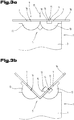
- Fig. 3a and 3b show the determination of the bending geometry, in particular the leg length, by determining the longitudinal offset of the sheet to be bent based on an embodiment of the bending tool 1 with pivoting jaws 13th
- Fig. 3a shows the situation in the initial state, in which on the contact surface 7 of the swivel jaw 13 a metal sheet 16 to be formed is arranged.
- the pivoting jaws 13 are pivotable about a, parallel to the laying line 9 pivot axis 14.
- the sensor 10 is arranged in the region of the laying edge or laying line 9 such that there is no displacement of the sensor in relation to the laying line 9 during pivoting of the swivel jaws 13 and thus only a relative movement of the sliding sheet 16 relative to the sensor 10 is determined.
- a force 17 is exerted on the sheet 16 during the bending process, whereby this is pressed into the bending recess 5.
- the swivel jaws 13 pivot about the axis 14, so that the contact surfaces 7 of the swivel jaws 13 always bear against the metal sheet 16.
- Fig. 3b shows the state in achieving the desired bending deformation, in particular, both pivoting jaws 13 are fully swung by the pressed into the bending recess 5 sheet 16.
- this value is determined by the machine control of the bending press, and the longitudinal offset 18, can be determined via the mathematical model of bending deformation, the currently achieved bending angle.
- the nominal values of the bending parameters With the nominal values of the bending parameters, a specific course of the material deformation between lay-up line 9 or contact edge 8 and the contact point of the bending punch will be established on the basis of the model. This deformation course will also cause a specific longitudinal offset 18. If the material characteristics deviate from the desired values, a deviation of the determined longitudinal offset from the expected longitudinal offset will occur in particular. Thus, the currently achieved bending geometry and in particular a deviation from the expected value can be determined.
- Fig. 4 shows a detailed view of the sensor 10 for determining a longitudinal offset using the example of a bending tool with swivel jaws.
- the conditions described can be applied directly to a lower tool for bending.
- the sensor 10 is arranged in the tool body 3 of the bending tool 1 in such a way that there is no offset of the sensor 10 in relation to the laying line 9 or the contact edge during the bending operation.
- the sheet to be bent 16 rests on the contact surface 7, and is from the descending Bending punch is pressed around the laying line 9 or contact edge against the contact surfaces 7 and thus bent.
- the sheet 16 is pressed in the direction of the bending recess, so that a virtual surface point 19 of the sheet metal surface will move relative to the sensor 10.
- the sensor 10 is formed by a lighting-21 and image-sensing device 22.
- a section on the sheet metal surface 20 is illuminated by the lighting device 21, which illuminated section is detected cyclically by the image capture device 22. Due to the always present surface structure of the sheet metal surface 20, a constantly changing surface pattern is detected by the image acquisition device 22 during the relative movement of the sheet 16 with respect to the sensor 10.
- the acquired images are processed by an evaluation circuit, not shown, and analyzed in order to determine a motion vector from successive images of the illuminated surface section. Based on the knowledge of the image acquisition frequency and the determined motion vector, the real longitudinal offset can be determined. About this longitudinal offset and knowledge of the geometry of the bending tool 1, in particular the bending recess, the current bending angle and the currently reached leg length can be determined.
- Such an embodiment of a sensor 10 with a lighting 21 and image capture device 22 is known for example from optical computer mice. There, from the movement of the sensor in relation to a surface, in particular a table surface, the movement of the computer mouse is detected and converted into the movement of a pointer on the screen.
- the detection section 11 of the sensor 10 is arranged at a distance from the contact surface 7 by an offset 15. This ensures that the pressed sheet 16 with high pressure against the contact surface 7 and the contact edge, the detection section 11 is not damaged in the relative movement.
- the advantage of the subject lower tool now lies in particular in the fact that substantially every bending machine can be equipped with the functionality of a bending geometry monitoring, without requiring design changes to the bending machine.
- An existing set of sub-tools can be extended by an objective sub-tool and thus allows monitoring of the bending curve and compliance with the desired bending geometry during the execution of the bending deformation.
- the objective functionality can be used in a folding machine, wherein the conditions described for the lower tool are transferred to the bending cheek.
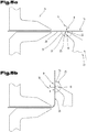
- Fig. 5 shows a bending tool assembly for use in pivoting bending, wherein the bending tool 1 is formed as a bending cheek 23.
- the bending tool assembly further comprises a hold-down tool 24, wherein the to be formed sheet 16 is clamped between the upper and lower hold-down tool.
- the sensor 10 is arranged, wherein the light emitting direction of the lighting device 21 and the detection range of the image sensing device 22 is aligned in the direction of the surface 20 of the sheet 16 to be formed.
- Fig. 5a shows the situation before the start of the bending deformation, in which the bending cheek 23 rests with or along the contact edge 8 on the surface 20 of the sheet 16.
- the coordinates of a surface point 19 in relation to the bending tool arrangement or in relation to the bending machine are determined.
- the further details of the reference formation of the surface point 19 have already been described above.
- Fig. 5b shows the situation after performing the bending deformation, in which the bending cheek 23 has been moved by a drive means of the bending machine along a path, and the bending cheek 23 is now in an end position. Due to the pivoting movement of the bending cheek 23, the surface point 19 has also shifted by the longitudinal offset 18 relative to the front end 25 of the bending cheek 23. From this longitudinal offset 18 and the knowledge of the movement path of the bending cheek 23, can be closed on the course of the bend between the front end 25 of the bending cheek and the hold-down tool 24 on the mathematical model of the bending deformation.
- a contact element 26 is arranged in the region of the front end 25 of the bending cheek 23, a contact element 26 is arranged. Due to the very complex course of the trajectory along which the bending cheek 23 is pivoted, it may happen that the contact edge 8 does not remain stationary with respect to the bending cheek 23. This situation is also in Fig. 5 recognizable. Due to the knowledge of the geometry of the bending cheek 23 in the region of the contact edge 8, this offset can be taken into account and thus has only a slight effect on the determination of the longitudinal offset 18. Under certain circumstances, however, there is an accuracy requirement for the bending geometry, which makes it necessary to take account of this displacement of the contact edge 8.
- the development with a contact element 26 now has the advantage that a decoupling of the force, from the drive means of the bending machine in / on the sheet, from the detection of the longitudinal offset 18 is possible.
- This contact element 26 is formed, for example, as a touch plate and preferably further comprises a flat side, which bears against the plate 16 and thus follows the pivoting of the sheet 16 in relation to the bending cheek 23. Since the contact element 26 is not subjected to force and therefore does not have to perform forming work, the pivotable bearing can be made very smooth. As a result, a very good adaptation to the bending sheet is possible and thus ensures an accurate detection of the longitudinal offset 18.
- the senor 10 follows in its orientation the pivoting movement of the contact element 26, for example by a non-positive and / or positive connection between the sensor and the contact element.
- the sensor 10 follows in its orientation the pivoting movement of the contact element 26, for example by a non-positive and / or positive connection between the sensor and the contact element.
- FIGS. 1 to 5 shown embodiments form the subject of independent solutions according to the invention, provided they fall within the scope of the claims.
- the relevant objects and solutions according to the invention can be found in the detailed descriptions of these figures.
Landscapes
- Engineering & Computer Science (AREA)
- Mechanical Engineering (AREA)
- Bending Of Plates, Rods, And Pipes (AREA)
Claims (25)
- Outil de pliage (1) avec un dispositif de mesure de décalage longitudinal (2),
destiné à être utilisé dans une machine de pliage en tant que partie d'une disposition d'outil de pliage, dans laquelle est disposée une tôle (16) à plier,
l'outil de pliage (1) comprenant un corps d'outil (3) avec une extension longitudinale (4), cette extension longitudinale (4) étant orientée parallèlement à une ligne de pliage et
parallèlement à cette extension longitudinale (4) et en direction de la tôle (16) à plier, sont formées deux surfaces d'appui (7) ou au moins une arête d'appui (8),
caractérisé en ce que
au niveau de l'arête d'appui (8) ou dans une surface d'appui (7), est disposé un capteur (10) pour la détermination d'un décalage longitudinal (18) de la tôle (16), une portion de détection (11) du capteur (10) étant orientée dans la direction d'une tôle (16) à plier. - Outil de pliage selon la revendication 1, caractérisé en ce que le capteur (10) est disposé sans décalage par rapport à l'arête d'appui (8) ou à une ligne d'appui (9).
- Outil de pliage selon l'une des revendications 1 ou 2, caractérisé en ce que le capteur (10) est conçu de manière pivotante autour de la ligne d'appui (9).
- Outil de pliage selon l'une des revendications 1 à 3, l'outil de pliage étant conçu comme un outil inférieur d'une presse de pliage, caractérisé en ce que les surfaces d'appui (7) sont constituées de mâchoires pivotantes (13), ces mâchoires pivotantes (13) étant pivotantes autour d'un axe de rotation (14) parallèle à la ligne d'appui (9).
- Outil de pliage selon l'une des revendications 1 à 3, l'outil de pliage étant conçu comme un outil inférieur d'une presse de pliage, caractérisé en ce que les surfaces d'appui (7) forment un évidement de pliage (5) d'une matrice de pliage en forme de V, cette matrice de pliage s'étendant à partir d'un côté plat supérieur (6) du corps d'outil (3) et en s'éloignant de la tôle (16) à former, vers le corps d'outil (3).
- Outil de pliage selon l'une des revendications 1 à 4, caractérisé en ce que le capteur (10) est constitué d'un dispositif d'éclairage (21) et d'un dispositif de capture d'images (22).
- Outil de pliage selon l'une des revendications 1 à 4, caractérisé en ce que le capteur (10) est constitué d'un émetteur et d'un récepteur pour un rayonnement électromagnétique.
- Outil de pliage selon l'une des revendications 4 à 6, caractérisé en ce que le capteur (10) est disposé dans un évidement d'au moins une des surfaces d'appui (7).
- Outil de pliage selon l'une des revendications 4 à 8, caractérisé en ce que le côté plat de détection du capteur (10) est disposé dans le corps d'outil (3), distant d'un décalage (15) de la surface d'appui (7).
- Outil de pliage selon l'une des revendications 1 à 9, caractérisé en ce que l'outil de pliage est une lame de pliage (23) d'une machine de pliage pivotante.
- Outil de pliage selon la revendication 10, caractérisé en ce que le capteur (10) est disposé dans une portion d'une extrémité avant (25) de la lame de pliage (23), cette extrémité avant (25) entrant en contact avec la tôle (16) pendant la réalisation du pliage.
- Outil de pliage selon la revendication 11, caractérisé en ce que, au niveau de l'extrémité avant (25), est disposé un élément de contact (26), cet élément de contact (26) pouvant être pivoté par rapport à la lame de pliage (23) autour de l'arête d'appui (8) ou étant maintenu de manière rotative autour d'un axe parallèle à l'arête d'appui (8).
- Outil de pliage selon la revendication 12, caractérisé en ce que l'élément de contact (26) comprend un côté plat dans lequel le capteur (10) est disposé et ce côté plat s'appuyant, lors du processus de pliage, contre la tôle (16).
- Outil de pliage selon la revendication 12, caractérisé en ce que l'élément de contact (26) est conçu comme un disque de palpage, ce disque de palpage roulant contre la tôle (16) lors du pliage.
- Outil de pliage selon l'une des revendications 1 à 10, caractérisé en ce que le capteur (10) est conçu comme un insert.
- Outil de pliage selon l'une des revendications 1 à 11, caractérisé en ce que le capteur (10) est relié avec un circuit d'analyse (12), qui est en outre relié à un contrôle de machine ou est intégré dans celle-ci.
- Outil de pliage selon les revendications 5 et 12, caractérisé en ce que le circuit d'analyse (12) comprend un module d'analyse d'image et de comparaison.
- Outil de pliage selon la revendication 17, caractérisé en ce que le module d'analyse d'image et de comparaison est conçu pour déterminer un vecteur de mouvement monodimensionnel ou bidimensionnel pour le décalage longitudinal (18).
- Outil de pliage selon l'une des revendications 1 à 14, caractérisé en ce que le capteur (10) est constitué d'un dispositif de roulement.
- Disposition d'outil de pliage, moyennant quoi, dans la disposition d'outil de plage, est disposé une tôle (16) à plier, caractérisée en ce qu'un outil de pliage (1) selon l'une des revendications 1 à 19 fait partie de la disposition d'outil de pliage.
- Procédé de détermination de la géométrie de pliage lors du pliage libre, exécuté sur une presse plieuse avec une disposition d'outil de pliage, cette disposition d'outil de pliage comprenant un outil inférieur et un outil supérieur,
l'outil inférieur étant un outil de pliage qui est conçu selon l'une des revendications 1 à 9 et 15 à 19 et
une pièce en tôle à plier étant insérée dans la disposition d'outil de pliage et la déformation par pliage libre étant effectuée grâce au fait que, du fait d'un abaissement de l'outil supérieur, la pièce en tôle est comprimée par l'outil supérieur dans un évidement de pliage de l'outil inférieur,
caractérisé en ce que
avant le début de la déformation par pliage, une surface de la pièce en tôle à plier est mise en contact avec un capteur pour al détermination d'un décalage longitudinal ;
et en ce que, pour, ce point de contact, des coordonnées de référence de la surface de la tôle par rapport à la machine de pliage ou à la disposition d'outil de pliage sont déterminées ;
et en ce que, pendant la déformation par pliage, un décalage longitudinal de la surface de la tôle par rapport au capteur est déterminé ;
et en ce que la géométrie de pliage actuelle est déterminée par un circuit d'analyse à partir du décalage longitudinal déterminé, selon un modèle mathématique de la déformation par pliage. - Procédé de détermination de la géométrie de pliage lors du pliage pivotant, exécuté sur une machine de pliage pivotant, avec une disposition d'outil de pliage, cette disposition d'outil de pliage comprenant un outil à dispositif de retenue (24) et au moins une lame de pliage (23),
une pièce en tôle à plier étant insérée dans la disposition d'outil de pliage et la déformation par pliage libre étant effectuée grâce au fait que la pièce en tôle est serrée par l'outil à dispositif de retenue (24) et la lame de pliage (23) est appuyée contre la pièce en tôle et est déplacée ou pivotée le long d'une trajectoire,
et la lame de pliage (23) étant un outil de pliage qui est conçu selon l'une des revendications 1 à 3, 6 à 7 et 10 à 19,
caractérisé en ce que
avant le début de la déformation par pliage, une surface de la pièce en tôle à plier est mise en contact avec un capteur pour la détermination d'un décalage longitudinal ;
et en ce que pour ce point de contact des coordonnées de référence de la surface de la tôle par rapport à la machine de pliage pivotant ou à la disposition d'outil de pliage sont déterminées ;
et en ce que, pendant la déformation par pliage, un décalage longitudinal de la surface de la tôle par rapport au capteur est déterminé ;
et en ce que la géométrie de pliage actuelle est déterminée par un circuit d'analyse à partir du décalage longitudinal déterminé, selon un modèle mathématique de la déformation par pliage. - Procédé selon la revendication 21, caractérisé en ce que, pendant la détermination du décalage longitudinal, le capteur est maintenu de manière stationnaire par rapport aux coordonnées de référence.
- Procédé selon la revendication 21 ou 23, caractérisé en ce que l'outil inférieur est conçu selon l'une des revendications 1 à 9 et le décalage longitudinal de la tôle par rapport à l'arête d'appui de l'outil inférieur est déterminé par le capteur.
- Procédé selon l'une des revendications 21 à 24, caractérisé en ce que le capteur est disposé, au moyen d'un dispositif de pivotement, au niveau de l'outil supérieur ou sur une table de presse de la presse plieuse, moyennant quoi, pendant la déformation par pliage, le dispositif de pivotement suit la tôle qui se plie.
Applications Claiming Priority (2)
| Application Number | Priority Date | Filing Date | Title |
|---|---|---|---|
| ATA50918/2014A AT516260B1 (de) | 2014-12-17 | 2014-12-17 | Biegewerkzeug mit einer Längsversatz-Messvorrichtung |
| PCT/AT2015/050316 WO2016094918A1 (fr) | 2014-12-17 | 2015-12-14 | Outil de cintrage ayant un dispositif de mesure de décalage longitudinal |
Publications (2)
| Publication Number | Publication Date |
|---|---|
| EP3233323A1 EP3233323A1 (fr) | 2017-10-25 |
| EP3233323B1 true EP3233323B1 (fr) | 2019-12-11 |
Family
ID=55229444
Family Applications (1)
| Application Number | Title | Priority Date | Filing Date |
|---|---|---|---|
| EP15828477.8A Not-in-force EP3233323B1 (fr) | 2014-12-17 | 2015-12-14 | Outil de cintrage ayant un dispositif de mesure de décalage longitudinal |
Country Status (4)
| Country | Link |
|---|---|
| US (1) | US10464114B2 (fr) |
| EP (1) | EP3233323B1 (fr) |
| AT (1) | AT516260B1 (fr) |
| WO (1) | WO2016094918A1 (fr) |
Families Citing this family (14)
| Publication number | Priority date | Publication date | Assignee | Title |
|---|---|---|---|---|
| AT516260B1 (de) * | 2014-12-17 | 2016-04-15 | Trumpf Maschinen Austria Gmbh | Biegewerkzeug mit einer Längsversatz-Messvorrichtung |
| CN106180472B (zh) * | 2016-07-13 | 2018-03-09 | 广州芯越数字控制系统有限公司 | 具有上模负载监控和保护装置的全电伺服数控的折弯机及其方法 |
| AT519002B1 (de) | 2016-09-16 | 2018-03-15 | Trumpf Maschinen Austria Gmbh & Co Kg | Biegewerkzeug, insbesondere ein Oberwerkzeug oder einen Biegestempel, und ein Betriebswechselverfahren |
| DE102016118175B4 (de) * | 2016-09-26 | 2018-08-23 | Trumpf Werkzeugmaschinen Gmbh & Co. Kg | Werkzeugmaschine und Verfahren zum Bearbeiten von plattenförmigen Werkstücken |
| CN107309302B (zh) * | 2017-07-07 | 2023-09-01 | 宁波横河精密工业股份有限公司 | 一种弯曲机 |
| AT520649B1 (de) * | 2018-05-07 | 2019-06-15 | Trumpf Maschinen Austria Gmbh & Co Kg | Verfahren mit einer Fertigungseinrichtung zum Umformen von Blech |
| CN111957842B (zh) * | 2020-06-22 | 2022-11-01 | 国机铸锻机械有限公司 | 一种折弯件及直形件的送进工艺及设备 |
| CN113145695B (zh) * | 2021-03-09 | 2022-07-26 | 陕西凯盛航空装备制造有限公司 | 一种便于维护的航空零部件生产用弯曲装置 |
| CN113399509A (zh) * | 2021-07-12 | 2021-09-17 | 孙伟城 | 一种机械零件加工用铝合金板折弯装置 |
| CN114749570B (zh) * | 2022-03-31 | 2023-03-24 | 南通华恩医疗设备制造有限公司 | 一种柔性冷冻消融针导电弹片的加工设备 |
| IT202200008012A1 (it) * | 2022-04-22 | 2023-10-22 | L M C Mecc S R L | Pressa per la piegatura di lamiere. |
| CN115446170B (zh) * | 2022-09-21 | 2023-09-05 | 邵东智能制造技术研究院有限公司 | 一种金属管成型加工装置及其使用方法 |
| CN118080726B (zh) * | 2024-04-19 | 2024-08-20 | 百超(天津)激光技术有限公司 | 用于折弯机的可旋转复位的光帘支架及其控制方法 |
| CN121551492B (zh) * | 2026-01-22 | 2026-03-20 | 沈阳天汽模航空部件有限公司 | 一种超长零件折弯前送料定位装置及方法 |
Family Cites Families (14)
| Publication number | Priority date | Publication date | Assignee | Title |
|---|---|---|---|---|
| EP0166351A3 (fr) | 1984-06-27 | 1986-09-17 | Arnold Stucki | Dispositif pour une machine de travail de déformation des tôles |
| DE4042732B4 (de) * | 1989-11-14 | 2004-09-16 | Amada Co., Ltd., Isehara | Verfahren zum Biegen eines Metallbleches und Biegemaschine mit einem Oberstempel und einer Matrize zum Biegen eines Metallbleches |
| EP1398094B1 (fr) * | 2002-09-11 | 2006-05-17 | Trumpf Werkzeugmaschinen GmbH + Co. KG | Procédé et dispositif pour déterminer la longueur de branche de pièces cintrées |
| WO2008140122A1 (fr) * | 2007-05-09 | 2008-11-20 | Nippon Steel Corporation | Dispositif et procédé de moulage par compression de plaque mince |
| DE102009019528B4 (de) * | 2008-06-27 | 2014-02-06 | Springer Gmbh | Einweiser zum Positionieren eines Werkstücks |
| DE102008038932A1 (de) * | 2008-08-13 | 2010-02-18 | Klingel, Hans, Dr. Ing. e.h. | Schwenkbiegemaschine |
| DE202010013721U1 (de) * | 2009-09-30 | 2011-04-28 | Micro-Epsilon Messtechnik Gmbh & Co. Kg | Vorrichtung zum Erfassen der Bewegung eines dünnen Körpers |
| AT511557B1 (de) | 2011-05-17 | 2013-08-15 | Trumpf Maschinen Austria Gmbh | Winkelmessvorrichtung für eine biegepresse |
| EP2529850B1 (fr) * | 2011-05-30 | 2013-09-11 | TRUMPF Werkzeugmaschinen GmbH + Co. KG | Capteur d'angle de pliage et procédé de mesure d'un angle de pliage |
| AT512282B1 (de) * | 2012-06-18 | 2013-07-15 | Trumpf Maschinen Austria Gmbh | Biegepresse mit Winkelerfassungsvorrichtung |
| EP3030359B1 (fr) * | 2013-08-09 | 2020-06-17 | Bystronic Laser AG | Presse à plier |
| EP2982933B1 (fr) * | 2014-08-07 | 2021-03-24 | SALVAGNINI ITALIA S.p.A. | Dispositif et procédé pour mesurer l'angle de pliage d'un objet |
| AT516260B1 (de) * | 2014-12-17 | 2016-04-15 | Trumpf Maschinen Austria Gmbh | Biegewerkzeug mit einer Längsversatz-Messvorrichtung |
| AT518890B1 (de) * | 2016-09-02 | 2018-02-15 | Trumpf Maschinen Austria Gmbh & Co Kg | Biegemaschine mit einer Arbeitsbereich-Bilderfassungsvorrichtung |
-
2014
- 2014-12-17 AT ATA50918/2014A patent/AT516260B1/de not_active IP Right Cessation
-
2015
- 2015-12-14 US US15/535,814 patent/US10464114B2/en active Active
- 2015-12-14 WO PCT/AT2015/050316 patent/WO2016094918A1/fr not_active Ceased
- 2015-12-14 EP EP15828477.8A patent/EP3233323B1/fr not_active Not-in-force
Non-Patent Citations (1)
| Title |
|---|
| None * |
Also Published As
| Publication number | Publication date |
|---|---|
| US10464114B2 (en) | 2019-11-05 |
| US20170333967A1 (en) | 2017-11-23 |
| WO2016094918A1 (fr) | 2016-06-23 |
| AT516260B1 (de) | 2016-04-15 |
| AT516260A4 (de) | 2016-04-15 |
| EP3233323A1 (fr) | 2017-10-25 |
Similar Documents
| Publication | Publication Date | Title |
|---|---|---|
| EP3233323B1 (fr) | Outil de cintrage ayant un dispositif de mesure de décalage longitudinal | |
| AT518993B1 (de) | Verfahren zum Betrieb einer Biegemaschine | |
| EP2878393B1 (fr) | Procédé d'enregistrement d'une dimension extérieure d'une pièce en forme de plaque | |
| EP3274110B1 (fr) | Outil de formage et procédé d'optimisation de formage de flan dans un outil de formage | |
| EP2311583B1 (fr) | Procédé de détermination de l'épaisseur d'une pièce à usiner à l'aide d'une plieuse et une telle plieuse | |
| DE102010016646B4 (de) | Verfahren zum Betrieb einer Fertigungspresse | |
| EP2092991B1 (fr) | Matrice à plier pour une presse à plier, notamment presse plieuse et procédé de pliage d'une pièce | |
| AT505743A1 (de) | Verfahren zur festlegung eines einstellparameterwerts einer biegepresse | |
| EP2771135B1 (fr) | Dispositif de pliage de tôles | |
| EP3207333A1 (fr) | Procédé de mesure d'angle de cintrage | |
| EP1342514A2 (fr) | Dispositif pour detecter un angle de cintrage d'un anneau, et procédé de régulation d'une cintreuse | |
| EP2995391B1 (fr) | Procede d'etalonnage pour une cintreuse et une telle cintreuse | |
| EP3655175B1 (fr) | Procédé de fonctionnement d'une installation d'usinage équipée d'un piston mobile | |
| DE102008038932A1 (de) | Schwenkbiegemaschine | |
| EP3215284B1 (fr) | Outil de cintrage avec dispositif de mesure de la géométrie de cintrage | |
| EP3566793A1 (fr) | Détection de matière en excès à couper pour cellules de pliage | |
| DE102018125035A1 (de) | Vorrichtung zum Umformen eines insbesondere metallischen Werkstücks | |
| EP2983842B1 (fr) | Presse plieuse avec un dispositif de mesure d'angle de pliage | |
| WO2015196224A1 (fr) | Dispositif de mesure d'angles de pliage destiné à une presse de pliage | |
| AT518560A1 (de) | Biegebalken für eine Schwenkbiegemaschine | |
| DE102018125032A1 (de) | Vorrichtung zum Umformen eines insbesondere metallischen Werkstücks | |
| EP3041617B1 (fr) | Ensemble outil de pliage permettant de déterminer l'angle de pliage | |
| DE10249300A1 (de) | Vorrichtung zur Erfassung eines Ringbiegewinkels, insbesondere eines Biegewinkels, eines Werkstücks, insbesondere eines Biegeteils, sowie ein Verfahren zur Regelung einer Biegemaschine | |
| DE102019119695A1 (de) | Vorrichtung zum Umformen eines Werkstücks | |
| DE102007004438A1 (de) | Markierungsvorrichtung |
Legal Events
| Date | Code | Title | Description |
|---|---|---|---|
| STAA | Information on the status of an ep patent application or granted ep patent |
Free format text: STATUS: THE INTERNATIONAL PUBLICATION HAS BEEN MADE |
|
| PUAI | Public reference made under article 153(3) epc to a published international application that has entered the european phase |
Free format text: ORIGINAL CODE: 0009012 |
|
| STAA | Information on the status of an ep patent application or granted ep patent |
Free format text: STATUS: REQUEST FOR EXAMINATION WAS MADE |
|
| 17P | Request for examination filed |
Effective date: 20170717 |
|
| AK | Designated contracting states |
Kind code of ref document: A1 Designated state(s): AL AT BE BG CH CY CZ DE DK EE ES FI FR GB GR HR HU IE IS IT LI LT LU LV MC MK MT NL NO PL PT RO RS SE SI SK SM TR |
|
| AX | Request for extension of the european patent |
Extension state: BA ME |
|
| DAV | Request for validation of the european patent (deleted) | ||
| DAX | Request for extension of the european patent (deleted) | ||
| STAA | Information on the status of an ep patent application or granted ep patent |
Free format text: STATUS: EXAMINATION IS IN PROGRESS |
|
| R17P | Request for examination filed (corrected) |
Effective date: 20170717 |
|
| 17Q | First examination report despatched |
Effective date: 20181016 |
|
| GRAP | Despatch of communication of intention to grant a patent |
Free format text: ORIGINAL CODE: EPIDOSNIGR1 |
|
| STAA | Information on the status of an ep patent application or granted ep patent |
Free format text: STATUS: GRANT OF PATENT IS INTENDED |
|
| INTG | Intention to grant announced |
Effective date: 20190129 |
|
| GRAJ | Information related to disapproval of communication of intention to grant by the applicant or resumption of examination proceedings by the epo deleted |
Free format text: ORIGINAL CODE: EPIDOSDIGR1 |
|
| STAA | Information on the status of an ep patent application or granted ep patent |
Free format text: STATUS: EXAMINATION IS IN PROGRESS |
|
| INTC | Intention to grant announced (deleted) | ||
| RIN1 | Information on inventor provided before grant (corrected) |
Inventor name: WALDHERR, MANFRED Inventor name: ANGERER, GERHARD Inventor name: HOERL, MATTHIAS Inventor name: HAUSMANN, FLORIAN Inventor name: FREUDENTHALER, KLEMENS Inventor name: KOVJENIC, NENAD Inventor name: GAGGL, JOSEF Inventor name: THEIS, HELMUT |
|
| GRAP | Despatch of communication of intention to grant a patent |
Free format text: ORIGINAL CODE: EPIDOSNIGR1 |
|
| STAA | Information on the status of an ep patent application or granted ep patent |
Free format text: STATUS: GRANT OF PATENT IS INTENDED |
|
| INTG | Intention to grant announced |
Effective date: 20190703 |
|
| GRAS | Grant fee paid |
Free format text: ORIGINAL CODE: EPIDOSNIGR3 |
|
| GRAA | (expected) grant |
Free format text: ORIGINAL CODE: 0009210 |
|
| STAA | Information on the status of an ep patent application or granted ep patent |
Free format text: STATUS: THE PATENT HAS BEEN GRANTED |
|
| AK | Designated contracting states |
Kind code of ref document: B1 Designated state(s): AL AT BE BG CH CY CZ DE DK EE ES FI FR GB GR HR HU IE IS IT LI LT LU LV MC MK MT NL NO PL PT RO RS SE SI SK SM TR |
|
| REG | Reference to a national code |
Ref country code: GB Ref legal event code: FG4D Free format text: NOT ENGLISH |
|
| REG | Reference to a national code |
Ref country code: CH Ref legal event code: EP |
|
| REG | Reference to a national code |
Ref country code: AT Ref legal event code: REF Ref document number: 1211683 Country of ref document: AT Kind code of ref document: T Effective date: 20191215 |
|
| REG | Reference to a national code |
Ref country code: DE Ref legal event code: R096 Ref document number: 502015011224 Country of ref document: DE |
|
| REG | Reference to a national code |
Ref country code: IE Ref legal event code: FG4D Free format text: LANGUAGE OF EP DOCUMENT: GERMAN |
|
| REG | Reference to a national code |
Ref country code: NL Ref legal event code: MP Effective date: 20191211 |
|
| REG | Reference to a national code |
Ref country code: LT Ref legal event code: MG4D |
|
| PG25 | Lapsed in a contracting state [announced via postgrant information from national office to epo] |
Ref country code: FI Free format text: LAPSE BECAUSE OF FAILURE TO SUBMIT A TRANSLATION OF THE DESCRIPTION OR TO PAY THE FEE WITHIN THE PRESCRIBED TIME-LIMIT Effective date: 20191211 Ref country code: BG Free format text: LAPSE BECAUSE OF FAILURE TO SUBMIT A TRANSLATION OF THE DESCRIPTION OR TO PAY THE FEE WITHIN THE PRESCRIBED TIME-LIMIT Effective date: 20200311 Ref country code: LT Free format text: LAPSE BECAUSE OF FAILURE TO SUBMIT A TRANSLATION OF THE DESCRIPTION OR TO PAY THE FEE WITHIN THE PRESCRIBED TIME-LIMIT Effective date: 20191211 Ref country code: SE Free format text: LAPSE BECAUSE OF FAILURE TO SUBMIT A TRANSLATION OF THE DESCRIPTION OR TO PAY THE FEE WITHIN THE PRESCRIBED TIME-LIMIT Effective date: 20191211 Ref country code: LV Free format text: LAPSE BECAUSE OF FAILURE TO SUBMIT A TRANSLATION OF THE DESCRIPTION OR TO PAY THE FEE WITHIN THE PRESCRIBED TIME-LIMIT Effective date: 20191211 Ref country code: NO Free format text: LAPSE BECAUSE OF FAILURE TO SUBMIT A TRANSLATION OF THE DESCRIPTION OR TO PAY THE FEE WITHIN THE PRESCRIBED TIME-LIMIT Effective date: 20200311 Ref country code: GR Free format text: LAPSE BECAUSE OF FAILURE TO SUBMIT A TRANSLATION OF THE DESCRIPTION OR TO PAY THE FEE WITHIN THE PRESCRIBED TIME-LIMIT Effective date: 20200312 |
|
| PG25 | Lapsed in a contracting state [announced via postgrant information from national office to epo] |
Ref country code: HR Free format text: LAPSE BECAUSE OF FAILURE TO SUBMIT A TRANSLATION OF THE DESCRIPTION OR TO PAY THE FEE WITHIN THE PRESCRIBED TIME-LIMIT Effective date: 20191211 Ref country code: RS Free format text: LAPSE BECAUSE OF FAILURE TO SUBMIT A TRANSLATION OF THE DESCRIPTION OR TO PAY THE FEE WITHIN THE PRESCRIBED TIME-LIMIT Effective date: 20191211 |
|
| PG25 | Lapsed in a contracting state [announced via postgrant information from national office to epo] |
Ref country code: AL Free format text: LAPSE BECAUSE OF FAILURE TO SUBMIT A TRANSLATION OF THE DESCRIPTION OR TO PAY THE FEE WITHIN THE PRESCRIBED TIME-LIMIT Effective date: 20191211 |
|
| PG25 | Lapsed in a contracting state [announced via postgrant information from national office to epo] |
Ref country code: EE Free format text: LAPSE BECAUSE OF FAILURE TO SUBMIT A TRANSLATION OF THE DESCRIPTION OR TO PAY THE FEE WITHIN THE PRESCRIBED TIME-LIMIT Effective date: 20191211 Ref country code: NL Free format text: LAPSE BECAUSE OF FAILURE TO SUBMIT A TRANSLATION OF THE DESCRIPTION OR TO PAY THE FEE WITHIN THE PRESCRIBED TIME-LIMIT Effective date: 20191211 Ref country code: RO Free format text: LAPSE BECAUSE OF FAILURE TO SUBMIT A TRANSLATION OF THE DESCRIPTION OR TO PAY THE FEE WITHIN THE PRESCRIBED TIME-LIMIT Effective date: 20191211 Ref country code: CZ Free format text: LAPSE BECAUSE OF FAILURE TO SUBMIT A TRANSLATION OF THE DESCRIPTION OR TO PAY THE FEE WITHIN THE PRESCRIBED TIME-LIMIT Effective date: 20191211 Ref country code: ES Free format text: LAPSE BECAUSE OF FAILURE TO SUBMIT A TRANSLATION OF THE DESCRIPTION OR TO PAY THE FEE WITHIN THE PRESCRIBED TIME-LIMIT Effective date: 20191211 Ref country code: PT Free format text: LAPSE BECAUSE OF FAILURE TO SUBMIT A TRANSLATION OF THE DESCRIPTION OR TO PAY THE FEE WITHIN THE PRESCRIBED TIME-LIMIT Effective date: 20200506 |
|
| REG | Reference to a national code |
Ref country code: CH Ref legal event code: PL |
|
| REG | Reference to a national code |
Ref country code: BE Ref legal event code: MM Effective date: 20191231 |
|
| PG25 | Lapsed in a contracting state [announced via postgrant information from national office to epo] |
Ref country code: SM Free format text: LAPSE BECAUSE OF FAILURE TO SUBMIT A TRANSLATION OF THE DESCRIPTION OR TO PAY THE FEE WITHIN THE PRESCRIBED TIME-LIMIT Effective date: 20191211 Ref country code: IS Free format text: LAPSE BECAUSE OF FAILURE TO SUBMIT A TRANSLATION OF THE DESCRIPTION OR TO PAY THE FEE WITHIN THE PRESCRIBED TIME-LIMIT Effective date: 20200411 Ref country code: SK Free format text: LAPSE BECAUSE OF FAILURE TO SUBMIT A TRANSLATION OF THE DESCRIPTION OR TO PAY THE FEE WITHIN THE PRESCRIBED TIME-LIMIT Effective date: 20191211 |
|
| REG | Reference to a national code |
Ref country code: DE Ref legal event code: R097 Ref document number: 502015011224 Country of ref document: DE |
|
| PG25 | Lapsed in a contracting state [announced via postgrant information from national office to epo] |
Ref country code: MC Free format text: LAPSE BECAUSE OF FAILURE TO SUBMIT A TRANSLATION OF THE DESCRIPTION OR TO PAY THE FEE WITHIN THE PRESCRIBED TIME-LIMIT Effective date: 20191211 |
|
| PLBE | No opposition filed within time limit |
Free format text: ORIGINAL CODE: 0009261 |
|
| STAA | Information on the status of an ep patent application or granted ep patent |
Free format text: STATUS: NO OPPOSITION FILED WITHIN TIME LIMIT |
|
| PG25 | Lapsed in a contracting state [announced via postgrant information from national office to epo] |
Ref country code: IE Free format text: LAPSE BECAUSE OF NON-PAYMENT OF DUE FEES Effective date: 20191214 Ref country code: DK Free format text: LAPSE BECAUSE OF FAILURE TO SUBMIT A TRANSLATION OF THE DESCRIPTION OR TO PAY THE FEE WITHIN THE PRESCRIBED TIME-LIMIT Effective date: 20191211 Ref country code: LU Free format text: LAPSE BECAUSE OF NON-PAYMENT OF DUE FEES Effective date: 20191214 |
|
| 26N | No opposition filed |
Effective date: 20200914 |
|
| PG25 | Lapsed in a contracting state [announced via postgrant information from national office to epo] |
Ref country code: SI Free format text: LAPSE BECAUSE OF FAILURE TO SUBMIT A TRANSLATION OF THE DESCRIPTION OR TO PAY THE FEE WITHIN THE PRESCRIBED TIME-LIMIT Effective date: 20191211 Ref country code: CH Free format text: LAPSE BECAUSE OF NON-PAYMENT OF DUE FEES Effective date: 20191231 Ref country code: LI Free format text: LAPSE BECAUSE OF NON-PAYMENT OF DUE FEES Effective date: 20191231 Ref country code: BE Free format text: LAPSE BECAUSE OF NON-PAYMENT OF DUE FEES Effective date: 20191231 |
|
| PG25 | Lapsed in a contracting state [announced via postgrant information from national office to epo] |
Ref country code: FR Free format text: LAPSE BECAUSE OF NON-PAYMENT OF DUE FEES Effective date: 20200211 |
|
| PG25 | Lapsed in a contracting state [announced via postgrant information from national office to epo] |
Ref country code: PL Free format text: LAPSE BECAUSE OF FAILURE TO SUBMIT A TRANSLATION OF THE DESCRIPTION OR TO PAY THE FEE WITHIN THE PRESCRIBED TIME-LIMIT Effective date: 20191211 |
|
| GBPC | Gb: european patent ceased through non-payment of renewal fee |
Effective date: 20200311 |
|
| PG25 | Lapsed in a contracting state [announced via postgrant information from national office to epo] |
Ref country code: GB Free format text: LAPSE BECAUSE OF NON-PAYMENT OF DUE FEES Effective date: 20200311 |
|
| PG25 | Lapsed in a contracting state [announced via postgrant information from national office to epo] |
Ref country code: CY Free format text: LAPSE BECAUSE OF FAILURE TO SUBMIT A TRANSLATION OF THE DESCRIPTION OR TO PAY THE FEE WITHIN THE PRESCRIBED TIME-LIMIT Effective date: 20191211 |
|
| PG25 | Lapsed in a contracting state [announced via postgrant information from national office to epo] |
Ref country code: MT Free format text: LAPSE BECAUSE OF FAILURE TO SUBMIT A TRANSLATION OF THE DESCRIPTION OR TO PAY THE FEE WITHIN THE PRESCRIBED TIME-LIMIT Effective date: 20191211 Ref country code: HU Free format text: LAPSE BECAUSE OF FAILURE TO SUBMIT A TRANSLATION OF THE DESCRIPTION OR TO PAY THE FEE WITHIN THE PRESCRIBED TIME-LIMIT; INVALID AB INITIO Effective date: 20151214 |
|
| PGFP | Annual fee paid to national office [announced via postgrant information from national office to epo] |
Ref country code: DE Payment date: 20211112 Year of fee payment: 7 |
|
| REG | Reference to a national code |
Ref country code: AT Ref legal event code: MM01 Ref document number: 1211683 Country of ref document: AT Kind code of ref document: T Effective date: 20201214 |
|
| PGFP | Annual fee paid to national office [announced via postgrant information from national office to epo] |
Ref country code: IT Payment date: 20211129 Year of fee payment: 7 |
|
| PG25 | Lapsed in a contracting state [announced via postgrant information from national office to epo] |
Ref country code: AT Free format text: LAPSE BECAUSE OF NON-PAYMENT OF DUE FEES Effective date: 20201214 |
|
| PG25 | Lapsed in a contracting state [announced via postgrant information from national office to epo] |
Ref country code: TR Free format text: LAPSE BECAUSE OF FAILURE TO SUBMIT A TRANSLATION OF THE DESCRIPTION OR TO PAY THE FEE WITHIN THE PRESCRIBED TIME-LIMIT Effective date: 20191211 |
|
| PG25 | Lapsed in a contracting state [announced via postgrant information from national office to epo] |
Ref country code: MK Free format text: LAPSE BECAUSE OF FAILURE TO SUBMIT A TRANSLATION OF THE DESCRIPTION OR TO PAY THE FEE WITHIN THE PRESCRIBED TIME-LIMIT Effective date: 20191211 |
|
| REG | Reference to a national code |
Ref country code: DE Ref legal event code: R119 Ref document number: 502015011224 Country of ref document: DE |
|
| PG25 | Lapsed in a contracting state [announced via postgrant information from national office to epo] |
Ref country code: DE Free format text: LAPSE BECAUSE OF NON-PAYMENT OF DUE FEES Effective date: 20230701 |
|
| PG25 | Lapsed in a contracting state [announced via postgrant information from national office to epo] |
Ref country code: IT Free format text: LAPSE BECAUSE OF NON-PAYMENT OF DUE FEES Effective date: 20221214 |