EP3233390B1 - Dispositif à mouvement plan - Google Patents
Dispositif à mouvement plan Download PDFInfo
- Publication number
- EP3233390B1 EP3233390B1 EP14821638.5A EP14821638A EP3233390B1 EP 3233390 B1 EP3233390 B1 EP 3233390B1 EP 14821638 A EP14821638 A EP 14821638A EP 3233390 B1 EP3233390 B1 EP 3233390B1
- Authority
- EP
- European Patent Office
- Prior art keywords
- mobile platform
- planar
- planar surface
- bearing system
- cables
- Prior art date
- Legal status (The legal status is an assumption and is not a legal conclusion. Google has not performed a legal analysis and makes no representation as to the accuracy of the status listed.)
- Not-in-force
Links
Images



Classifications
-
- B—PERFORMING OPERATIONS; TRANSPORTING
- B25—HAND TOOLS; PORTABLE POWER-DRIVEN TOOLS; MANIPULATORS
- B25J—MANIPULATORS; CHAMBERS PROVIDED WITH MANIPULATION DEVICES
- B25J9/00—Program-controlled manipulators
- B25J9/003—Program-controlled manipulators having parallel kinematics
- B25J9/0078—Program-controlled manipulators having parallel kinematics actuated by cables
Definitions
- the present invention relates to the field of planar motion mechanisms and, in particular, to planar motion mechanisms and robotic devices based on planar motion mechanisms which permit the positioning of actuators, manipulators, tools or any other element, for activities of production, manipulation, modification or inspection.
- cables are light-weighted and can be extended in large workspace. Tensioned cables can be used to apply pulling forces. That is why in most cable-based parallel planar robots, cables are responsible for the function of actuation. To achieve the planar constraints, different solutions exist.
- German patent DE102010015530-B4 describes a cable-based planar motion mechanism having a vertical arrangement, in which the virtual plane can only be parallel to the gravity force.
- the mobile platform which is actuated by several cables in the vertical plane, moves in the virtual vertical plane against gravity force.
- the mechanism has very poor resistance to perturbations coming from outside of the virtual plane.
- United States patent US7246445-B2 refers to a cable-based planar mechanism in which a physic flat table is used. The mobile platform is located on this table and several cables are used to actuate the movement of the mobile platform in the plane that is parallel to the table. This arrangement offers a better unilateral perturbation than that of DE102010015530-B4 , because the mobile platform can push against the table.
- US7246445-B2 indicates that the table may be aligned horizontally and may also run diagonally to the horizontal, up to a vertical position, in fact no means for keeping the mobile platform against the table during the movement has been mentioned. It can therefore be understood from its description that it is only the portions of gravity force which keep the mobile platform against the table during the movement of the mobile platform.
- Patent application EP-A1-2 578 367 upon which the preamble of claim 1 is based, partially solves the above-mentioned problems by providing a cable-based planar motion mechanism in which obliquely extended cables guarantee the movement of the mobile platform against a supporting table.
- the mechanism can work in any orientation, as the table together with the obliquely extended cables offer bilateral constraints to keep the movement of the mobile platform in a plane.
- the platform can work on inclined surfaces and even upside down surfaces thanks to an attraction system between the platform and the working surface.
- This attraction system is generated by a perpendicular component of the cables forces: since the cables have an oblique orientation with respect to the work surface, a force component is generated on the platform which constantly maintains it against the work surface.
- this implementation requires high tensions in the cables. Consequently, the power consumption of actuators is increased, requiring that much more powerful actuators be used in comparison the ones needed to solely generate the target movement.
- a positioning device comprising a planar surface, a mobile platform configured to slide along said planar surface and cables for positioning and moving said mobile platform along said planar surface.
- the mobile platform comprises a planar bearing system located at the side of the mobile platform configured to slide along the planar surface, said planar bearing system comprising: means for pushing the mobile platform against the planar surface; and means for allowing sliding of said planar bearing system with respect to the planar surface.
- the means for pushing the mobile platform against the planar surface comprises a vacuum chamber.
- the means for pushing the mobile platform against the planar surface further comprises sealing means.
- the means for allowing sliding of said planar bearing system with respect to the planar surface comprises at least one caster ball.
- the means for pushing the mobile platform against the planar surface comprises a magnetic system.
- the planar bearing system comprises at least one air bearing.
- the planar bearing system comprises at least one vacuum preloaded air bearing.
- the device further comprises a gripping device attached to said mobile platform.
- the mobile platform is located under said planar surface.
- the term “approximately” and terms of its family should be understood as indicating values very near to those which accompany the aforementioned term. That is to say, a deviation within reasonable limits from an exact value should be accepted, because a skilled person in the art will understand that such a deviation from the values indicated is inevitable due to measurement inaccuracies, etc. The same applies to the terms “about” and “around” and “substantially”.
- FIGS 1A, 1B and 1C show a schematic representation of the positioning device 1.
- Figure 1D and 1E show alternative embodiments of the positioning device 1.
- the positioning device 1 comprises a frame 2 supporting a planar element or planar surface 3 and a mobile platform 4 which can slide on the surface defined by the planar element 3.
- the mobile platform 4 is preferably located or suspended under the planar surface 3.
- the mobile platform 4 can be located or suspended above the planar surface 3.
- This implementation is suitable for pick & place robots, in which a grasping element is attached to the mobile platform 4.
- the planar element 3 (and therefore the mobile platform 4 connected thereto) can have any orientation.
- the planar surface 3 is not necessarily parallel to the floor, but can be inclined or vertical (perpendicular) with respect to the floor, which is considered as reference system.
- the mobile platform 4 then slides on the face of the planar surface on which it is located (which is preferably the lower face but can alternatively be the upper one, depending on the application for which it is configured), either in parallel to the floor or in oblique orientation with respect to the floor or perpendicular (vertical plane) to the floor. In other words, the mobile platform 4 can work upside down. This means that the mobile platform 4 is able to work either on a horizontal planar surface (as illustrated for example in figure 1B , which shows a mobile platform working upside down), on a vertical planar surface, or an inclined planar surface.
- Figures 1A , 1D and 1E also show some cables 6.
- the function of the cables 6 is to control the allowed movements of the mobile platform 4. Thanks to the planar element 3 and the planar bearing system 5 (which is explained in detail later), the allowed movements of the mobile platform 4 are the movements along the planar element 3, which comprises translations along axes that are parallel to the planar element 3 and rotations along axes that are perpendicular to the planar element 3. By adjusting the lengths and/or tensions of at least one of the cables 6, such allowed movements along the planar element 3 are controlled.
- the cables 6 contribute to overcome various perturbations on the mobile platform which can be caused by various reasons according to the set-up and applications of the positioning device. For example, such perturbations can be gravity, other external forces exerted on the mobile platform, reaction forces exerted by accelerating components on the mobile platform, etc.
- the positioning device 1 comprises at least three tension elements or cables 6, as depicted in figure 1D , each of which are linked at one end to the mobile platform 4 and at the other end to actuating means (schematically referred to as 7).
- the function of the cables is to control movement of the platform. If there are 3 cables, like in the implementation of figure 1D , the position (x, y) of the mobile platform is controlled independently (but not its orientation, since the equilibrium orientation of the mobile platform depends on its position). If there are 4 cables, like in the implementation of figure 1A , not only the position of the platform, but also its orientation, are controlled independently.
- each cable 6 controls three independent degrees of freedom: position (x, y) and rotation (z), wherein the controlled rotation is along axes that are perpendicular to the planar element 3.
- the tension elements 6 exert forces on the mobile platform 4, allowing its positioning and moving on the planar surface 3.
- These four tension elements or cables 6 permit obtaining the position and controlled rotation (or absence of rotation) of the mobile platform 4.
- the end of each cable 6 which is linked to the actuating means 7, is attached to a cable gathering and release mechanism which controls the length and tension of the corresponding cable and which preferably remains fixed on the frame.
- the other end of each cable 6 is anchored to the mobile platform 4.
- the operation of the cable gathering and release mechanism allows displacing the mobile platform 4 along the entire planar surface 3 in a controlled manner and precisely positioning it.
- the attaching points of the cables 6 on the mobile platform 4 can either stay in a planar surface or in any other way.
- the actuating means 7, which is attached to a cable gathering and release mechanism which controls the length and tension of the corresponding cable, can be fixed on the mobile platform 4.
- the other end of each cable 6 is anchored to the frame 2.
- the mobile platform 4 comprises a planar bearing system 5 located at the side of the mobile platform 4 configured to slide along the planar surface 3.
- the planar bearing system 5 maintains the mobile platform 4, regardless of the orientation of the planar surface 3, supported against the planar surface 3 and in equilibrium with any external or internal excitation.
- the planar bearing system is responsible for the attachment of the mobile platform 4 to the planar surface 3.
- the planar bearing system 5 and the planar surface 3 restrict three degrees of freedom of the mobile platform 4: two rotations and one displacement.
- the cables 6 allow controlling the rotation on the shaft (z) perpendicular to the planar surface 3, as well as two displacements on the plane of the surface (x, y).
- the planar bearing system 5 comprises means for pushing the mobile platform 4 against the planar surface 3, thus preventing the mobile platform 4 from separating from the planar surface 3 or from rotating in an axis parallel to the planar surface 3; and means for allowing sliding of the planar bearing system 5 with respect to the planar surface 3.
- FIG. 1C illustrates the principle of action of the planar bearing system, in which the upwards arrows indicate attraction force which pushes the planar bearing system towards the planar surface, while the downwards arrows indicate the repulsion force that stops the planar bearing system approaching or penetrating into the planar bearing surface. In most cases, these two forces exist simultaneously on the planar bearing system. The resultant force of these two forces contribute to overcome various perturbation forces on the mobile platform caused by various factors (such as external forces on mobile platform, forces or torques generated by cables, installation directions of the system regarding to gravity etc.)
- the planar bearing system 5 has the function of constraining three degrees of freedom (one translation along axes that are perpendicular to the planar element 3 and two rotations along axes that are parallel to the planar element 3) of the mobile platform 4.
- the planar bearing system 5 keeps the mobile platform 4 pushed towards the planar surface 3. It also permits sliding the mobile platform on the planar surface. It provides the mobile platform 4 with resistance to perturbation forces and torques that may cause parasite movement of the mobile platform 4 outside of the plane (planar surface 3).
- the planar bearing system 5 can provide an attraction force (or attaching force) or attraction forces between the mobile platform and the planar surface.
- the planar bearing system 5 comprises means for being attached to (pushing towards) the planar surface 3 by exerting an attaching force (also called attraction force), and means for being slided on the planar surface 3 by exerting a supporting force or pushing force.
- an attaching force also called attraction force
- FIG. 2A shows a possible embodiment of a mobile platform 24 comprising a planar bearing system 25.
- the planar bearing system is formed by at least one air bearing 25.
- the number of necessary air bearings depends on several factors, such as, the wrench (perpendicular force and parallel torques) the bearing is supposed to resist to, their dimensions, the dimensions and weight of the tool they are configured to carry, among others.
- the planar bearing system 25 of figure 2A is formed by three air bearings.
- the air bearings 25 permit the contactless sliding of the mobile platform 24 along two axis x y (that is to say, on a plane parallel to the supporting surface 3, not illustrated in figure 2A ) and rotation around the z axis perpendicular to the planar surface.
- Supporting elements 27A 27B 27C are used as a structure for the planar bearing system 25 and for the remaining elements of the mobile platform 24.
- the attachments 26 for the cables are also illustrated in the mobile platform 24. In the shown view, only two attachments 26 are shown, of a total of four attachments. The action of the cables also permits limited rotation and translations.
- a gripping device 29 has been connected to the lower end of the mobile platform 24.
- the selection of the gripping element or any other element to be used depends on the particular application for which the device is used.
- Actuating means 28 for actuating the gripping device 29 are also shown in figure 2A .
- the actuating means are independent motors 28 which provide independent movements of rotation and translation.
- "z axis" refers to the translation axis of the gripping device 29, and 'theta axis' refers to the rotation axis of the gripping device.
- FIG. 2B shows a schematic representation of a vacuum preloaded air bearing 25, in which its working principle is illustrated.
- the vacuum preloaded air bearing 25 receives two opposite forces 254 255 (also illustrated as solid arrows in figure 1C ).
- the upwards arrows 255 indicate attraction force which keeps the air bearing against the planar surface while the downwards arrows 254 indicate pushing force that stops the air bearing approaching further towards the planar surface.
- the illustrated vacuum preloaded air-bearing uses high pressure air for generating repulsion force 254 and vacuum chamber for generating attraction force 255.
- a vacuum 253 is created between the vacuum preloaded air bearing 25 and the surface 23 on which the mobile platform is to slide. As shown in figure 2B , the vacuum preloaded air bearing 25 is contactless with respect to this surface 23. There is no friction between them.
- the vacuum 253 works as means for pushing the preloaded air-bearing towards the surface, but thanks to the repulsion force 254, no physical contact between the air bearing and the surface is established.
- FIG 3 shows an alternative embodiment of the planar bearing system 35 (and mobile platform 34 in which it is comprised).
- the planar bearing system 35 is formed by at least one vacuum chamber 351 and means for sliding 352 of the mobile platform 34 along a plane parallel to the supporting surface (not illustrated).
- the planar bearing system 35 is circular in this figure, but other shapes are also possible, such as oval or pseudo-circular.
- a seal 353 (annular seal in figure 3 ) flexibly connects -with contact-the planar bearing system 35 to the surface along which it slides.
- the seal 353 is made of a combination or rubber and Teflon (or any preloaded low-friction air-tight compound).
- the means for sliding 352 are a plurality of caster balls. Preferably three caster balls 352 are used. In alternative embodiments, the means for sliding 352 are at least one magnetic element or at least one friction disc surfaces or pressure means by air.
- the caster balls 352 (or alternative sliding means) permit the sliding with physical contact of the mobile platform 34 along a plane parallel to the supporting surface. The balls permit the sliding between the platform and the surface. The balls are in contact with the planar surface and roll on it.
- a vacuum system provides vacuum forces to the vacuum chamber 351, which acts as a means for attaching the mobile platform 34 to the planar surface. In figure 3 the balls are housed within the vacuum chamber 351, but they could be outside instead.
- Figure 3 also shows a gripping tool 39 attached to the mobile platform 34.
- the gripping tool 39 has been included with exemplary purpose and is not limited to the kind of planar bearing system of figure 3 .
- the structure and supporting elements are within a box or sleeve 37. This configuration is particularly useful in the foodstuff industry, in which the hygienic requirements are very strict.
- Within the sleeve 37 there are also additional needed elements, such as electro-valves, electric sensors and so on.
- Four cables 36 are illustrated, as well as their corresponding attachments. The action of the cables permits limited rotation.
- the sleeve 37 also hides the actuating means which are necessary for actuating the gripping tool 39.
- the means for sliding is either a mechanical sliding friction bearing, such as a frictional disc, or a caster ball bearing, or an omni wheel, or a pressure air means or a magnetic means, or any other mechanism which enables sliding along a surface.
- a mechanical sliding friction bearing such as a frictional disc, or a caster ball bearing, or an omni wheel, or a pressure air means or a magnetic means, or any other mechanism which enables sliding along a surface.
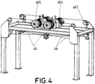
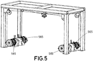
- Figures 4 , 5 and 6 show different embodiments of positioning devices controlled by cables according to the present invention.
- the location of the elements for controlling and actuating the cables can vary without altering the correct functioning of the positioning device.
- the four actuators 465 (one per cable 46) are located above the planar surface 43.
- the mobile platform moves along the lower face of the planar surface 43.
- a pulley system formed by four pulleys 467 can be used as guiding means to ease movement. This configuration for the actuating means is recommended in applications in which strict hygienic constraints are imposed.
- the four actuators 565 are located on the floor, close to the structure which supports the positioning device.
- Figure 6 shows an embodiment where the actuators 655 are installed at the same height of the mobile platform, so that no pulleys 467 such as in figure 4 and figure 5 are needed for guiding the cable routing.
- a tool for example a grasping element, is connected to the positioning device 1. Any other end-effector can be installed, depending on the needs of the application for which the robot is configured to work.
- the system comprises a supporting surface and a mobile platform comprising a planar bearing system. Any element, such as a load, a robot arm or a gripping element, can be attached to the mobile platforms to perform complex tasks.
- the system can additionally include at least one control unit and other elements, such as encoders and motors, which are out of the scope of the present invention.
- the frame can be fixed on the ground, on a wall, on another frame acting as a main frame or on a mobile base.
Landscapes
- Engineering & Computer Science (AREA)
- Robotics (AREA)
- Mechanical Engineering (AREA)
- Manipulator (AREA)
- Machine Tool Units (AREA)
- Details Of Measuring And Other Instruments (AREA)
- Bearings For Parts Moving Linearly (AREA)
Claims (10)
- Dispositif de positionnement (1) comprenant une surface plane (3), une plate-forme mobile (4, 24, 34) configurée pour coulisser le long de ladite surface plane (3), et des câbles (6) pour positionner et déplacer ladite plate-forme mobile (4, 24, 34) le long de ladite surface plane (3), la plate-forme mobile (4, 24, 34) comprenant un système de coussinet plan (5, 25, 35) situé du côté de la plate-forme mobile (4, 24, 34) configuré pour coulisser le long de la surface plane (3), ledit système de coussinet plan (5, 25, 35) comprenant des moyens pour permettre le coulissement dudit système de coussinet plan (5, 25, 35) par rapport à la surface plane (3),
le dispositif de positionnement (1) étant caractérisé en ce que ledit système de coussinet plan (5, 25, 35) comprend en outre des moyens pour pousser la plate-forme mobile (4, 24, 34) contre la surface plane (3). - Dispositif (1) selon la revendication 1, dans lequel lesdits moyens pour pousser la plate-forme mobile (34) contre la surface plane (3) comprennent une chambre à vide (351)
- Dispositif (1) selon la revendication 1 ou 2, dans lequel lesdits moyens pour permettre le coulissement dudit système de coussinet plan (35) par rapport à la surface plane (3) comprennent au moins une bille de roulette (352).
- Dispositif (1) selon la revendication 2, dans lequel lesdits moyens pour pousser la plate-forme mobile (34) contre la surface plane (3) comprennent en outre des moyens d'étanchéité (353).
- Dispositif (1) selon la revendication 1, dans lequel lesdits moyens pour pousser la plate-forme mobile (4) contre la surface plane (3) comprennent un système magnétique.
- Dispositif (1) selon la revendication 1 ou 2, dans lequel ledit système de coussinet plan (25) comprend au moins un coussinet pneumatique.
- Dispositif (1) selon la revendication 1, dans lequel ledit système de coussinet plan (25) comprend au moins un coussinet à air précontraint sous vide.
- Dispositif (1) selon l'une quelconque des revendications précédentes, comprenant en outre un dispositif de préhension fixé à ladite plate-forme mobile (4, 24, 34).
- Dispositif (1) selon l'une quelconque des revendications précédentes, dans lequel ladite plate-forme mobile (4) est située sous ladite surface plane (3).
- Utilisation du dispositif (1) selon l'une quelconque des revendications précédentes en tant que robot preneur-placeur.
Applications Claiming Priority (1)
| Application Number | Priority Date | Filing Date | Title |
|---|---|---|---|
| PCT/EP2014/078932 WO2016096057A1 (fr) | 2014-12-19 | 2014-12-19 | Dispositif à mouvement plan |
Publications (2)
| Publication Number | Publication Date |
|---|---|
| EP3233390A1 EP3233390A1 (fr) | 2017-10-25 |
| EP3233390B1 true EP3233390B1 (fr) | 2019-02-20 |
Family
ID=52278639
Family Applications (1)
| Application Number | Title | Priority Date | Filing Date |
|---|---|---|---|
| EP14821638.5A Not-in-force EP3233390B1 (fr) | 2014-12-19 | 2014-12-19 | Dispositif à mouvement plan |
Country Status (6)
| Country | Link |
|---|---|
| US (1) | US10449668B2 (fr) |
| EP (1) | EP3233390B1 (fr) |
| CN (1) | CN107427999B (fr) |
| ES (1) | ES2730251T3 (fr) |
| MX (1) | MX379152B (fr) |
| WO (1) | WO2016096057A1 (fr) |
Families Citing this family (3)
| Publication number | Priority date | Publication date | Assignee | Title |
|---|---|---|---|---|
| US11446812B2 (en) * | 2017-12-22 | 2022-09-20 | Marchesini Group S.P.A. | Cable-driven robot |
| CN108942897B (zh) * | 2018-09-12 | 2023-11-17 | 杭州国辰机器人科技有限公司 | 一种船体外表面绳牵引并联喷涂机器人 |
| US20210379768A1 (en) * | 2020-06-03 | 2021-12-09 | Everseen Limited | Aerial navigation system |
Family Cites Families (20)
| Publication number | Priority date | Publication date | Assignee | Title |
|---|---|---|---|---|
| US2746151A (en) * | 1951-11-17 | 1956-05-22 | Collins Radio Co | Tracking mechanism |
| US3492421A (en) * | 1966-07-05 | 1970-01-27 | Iit Res Inst | Graphical translator |
| FR2398937A1 (fr) * | 1977-07-25 | 1979-02-23 | Lectra Systemes Sa | Dispositif d'entrainement et deplacement d'une poutre reposant sur deux rails de guidage et d'un ou plusieurs chariots solidaires de la poutre |
| US4412383A (en) * | 1981-08-13 | 1983-11-01 | Benzion Landa | Cable driven plotter |
| US4918817A (en) * | 1987-09-28 | 1990-04-24 | Eaton Homer L | Article positioning apparatus |
| US4856197A (en) * | 1988-05-13 | 1989-08-15 | Buddy L Corporation | Drawing device having retractable stylus |
| CH675986A5 (fr) * | 1988-05-26 | 1990-11-30 | Wild Leitz Ag | |
| JPH05228770A (ja) | 1990-07-20 | 1993-09-07 | Nikotetsuku:Kk | 平面運動機構 |
| SE506213C2 (sv) * | 1996-03-20 | 1997-11-24 | Johansson Ab C E | Anordning för att åstadkomma en i huvudsak rätlinjig rörelse hos en rörlig del i en mätmaskin där kraftöverföringen sker från en typ av rörelse till den linjära rörelsen |
| US6457792B1 (en) * | 1999-11-29 | 2002-10-01 | Xerox Corporation | Method for effecting actions over vertical surfaces |
| DE10359273A1 (de) * | 2003-12-17 | 2005-07-21 | Erich Thallner | Justiervorrichtung |
| US20080052928A1 (en) * | 2006-09-05 | 2008-03-06 | Parel Thomas M | Self-leveling line generator |
| CN100493861C (zh) * | 2007-01-31 | 2009-06-03 | 哈尔滨工业大学深圳研究生院 | 一种三自由度平面并联机器人机构 |
| CN201009241Y (zh) * | 2007-02-08 | 2008-01-23 | 永联邦精密工业股份有限公司 | 平板支撑装置 |
| DE102010015530B4 (de) | 2010-04-20 | 2012-09-06 | Sandra Wahle | Lagersystem, insbesondere Regallager |
| EP2578367B1 (fr) | 2010-05-27 | 2014-04-09 | Fundacion Tecnalia Research & Innovation | Dispositif de positionnement commandé par des câbles |
| CH703454B1 (de) | 2010-07-16 | 2014-06-30 | Jossi Holding Ag | Vorrichtung zum Positionieren eines Objekts, insbesondere einer Pipette. |
| US8919003B1 (en) * | 2012-02-13 | 2014-12-30 | Fsm Plasticoid Manufacturing, Inc. | Parallel straightedge drafting board |
| US8732972B2 (en) * | 2012-02-23 | 2014-05-27 | Garland R. Jordan | Framing tool |
| KR101627766B1 (ko) * | 2014-02-04 | 2016-06-07 | 전남대학교산학협력단 | 케이블 기반 병렬형 로봇을 위한 케이블 연결 위치 변경장치 |
-
2014
- 2014-12-19 EP EP14821638.5A patent/EP3233390B1/fr not_active Not-in-force
- 2014-12-19 US US15/537,762 patent/US10449668B2/en not_active Expired - Fee Related
- 2014-12-19 WO PCT/EP2014/078932 patent/WO2016096057A1/fr not_active Ceased
- 2014-12-19 CN CN201480084569.9A patent/CN107427999B/zh active Active
- 2014-12-19 MX MX2017008255A patent/MX379152B/es unknown
- 2014-12-19 ES ES14821638T patent/ES2730251T3/es active Active
Non-Patent Citations (1)
| Title |
|---|
| None * |
Also Published As
| Publication number | Publication date |
|---|---|
| MX2017008255A (es) | 2018-04-10 |
| CN107427999A (zh) | 2017-12-01 |
| WO2016096057A1 (fr) | 2016-06-23 |
| ES2730251T3 (es) | 2019-11-11 |
| CN107427999B (zh) | 2021-03-26 |
| US10449668B2 (en) | 2019-10-22 |
| US20180009103A1 (en) | 2018-01-11 |
| EP3233390A1 (fr) | 2017-10-25 |
| MX379152B (es) | 2025-03-11 |
Similar Documents
| Publication | Publication Date | Title |
|---|---|---|
| CN110545962B (zh) | 线缆驱动式并联操纵器 | |
| CN106584428B (zh) | 用于线性柔性的铰接式机构 | |
| CN107215404B (zh) | 机器人、机器人系统及相关的方法 | |
| US9688328B2 (en) | Compact hoist for overhead applications | |
| JP5981811B2 (ja) | 搬送システム及び搬送システムの搬送方法 | |
| US10759634B2 (en) | Electromechanical system for interaction with an operator | |
| RU2014122527A (ru) | Стационарный робот для ручных микроманипуляций | |
| US9540186B2 (en) | Conveyor system and conveyance method | |
| JP6580250B2 (ja) | 作業ユニット用の補償装置ならびに補償装置を備えた作業ユニット | |
| US10449668B2 (en) | Planar motion device | |
| JP5907900B2 (ja) | 回転式複数部品把持具 | |
| US10052758B2 (en) | Method for controlling a manipulator system | |
| CN112643662B (zh) | 一种具有力觉感知的多自由度操作机器人 | |
| JP2018126807A (ja) | ワーク搬送装置 | |
| KR20190121822A (ko) | 로봇 아암 | |
| WO2016067457A1 (fr) | Système de transfert et son procédé de commande | |
| US11878431B2 (en) | End effector and member mounting method | |
| US20180222041A1 (en) | Robot system | |
| US11124977B2 (en) | System and method for constructing a brick structure with a cable-driven robot | |
| Behzadipour et al. | DeltaBot: A new cable-based ultra high speed robot | |
| WO2019046898A1 (fr) | Manipulateur parallèle translationnel | |
| KR102643014B1 (ko) | 태양전지 모듈 자동 설치장치 | |
| KR101741689B1 (ko) | 탈착이 용이한 케이블 로봇용 엔드 이펙터 | |
| KR101794963B1 (ko) | 작업공간 가변형 케이블 로봇 | |
| JP7508116B2 (ja) | ドローンを用いた荷重取扱装置 |
Legal Events
| Date | Code | Title | Description |
|---|---|---|---|
| STAA | Information on the status of an ep patent application or granted ep patent |
Free format text: STATUS: THE INTERNATIONAL PUBLICATION HAS BEEN MADE |
|
| PUAI | Public reference made under article 153(3) epc to a published international application that has entered the european phase |
Free format text: ORIGINAL CODE: 0009012 |
|
| STAA | Information on the status of an ep patent application or granted ep patent |
Free format text: STATUS: REQUEST FOR EXAMINATION WAS MADE |
|
| 17P | Request for examination filed |
Effective date: 20170626 |
|
| AK | Designated contracting states |
Kind code of ref document: A1 Designated state(s): AL AT BE BG CH CY CZ DE DK EE ES FI FR GB GR HR HU IE IS IT LI LT LU LV MC MK MT NL NO PL PT RO RS SE SI SK SM TR |
|
| AX | Request for extension of the european patent |
Extension state: BA ME |
|
| DAX | Request for extension of the european patent (deleted) | ||
| GRAP | Despatch of communication of intention to grant a patent |
Free format text: ORIGINAL CODE: EPIDOSNIGR1 |
|
| STAA | Information on the status of an ep patent application or granted ep patent |
Free format text: STATUS: GRANT OF PATENT IS INTENDED |
|
| INTG | Intention to grant announced |
Effective date: 20180820 |
|
| GRAS | Grant fee paid |
Free format text: ORIGINAL CODE: EPIDOSNIGR3 |
|
| GRAA | (expected) grant |
Free format text: ORIGINAL CODE: 0009210 |
|
| STAA | Information on the status of an ep patent application or granted ep patent |
Free format text: STATUS: THE PATENT HAS BEEN GRANTED |
|
| AK | Designated contracting states |
Kind code of ref document: B1 Designated state(s): AL AT BE BG CH CY CZ DE DK EE ES FI FR GB GR HR HU IE IS IT LI LT LU LV MC MK MT NL NO PL PT RO RS SE SI SK SM TR |
|
| REG | Reference to a national code |
Ref country code: GB Ref legal event code: FG4D |
|
| REG | Reference to a national code |
Ref country code: CH Ref legal event code: EP |
|
| REG | Reference to a national code |
Ref country code: DE Ref legal event code: R096 Ref document number: 602014041431 Country of ref document: DE |
|
| REG | Reference to a national code |
Ref country code: AT Ref legal event code: REF Ref document number: 1097576 Country of ref document: AT Kind code of ref document: T Effective date: 20190315 |
|
| REG | Reference to a national code |
Ref country code: IE Ref legal event code: FG4D |
|
| REG | Reference to a national code |
Ref country code: NL Ref legal event code: FP |
|
| REG | Reference to a national code |
Ref country code: SE Ref legal event code: TRGR |
|
| REG | Reference to a national code |
Ref country code: LT Ref legal event code: MG4D |
|
| PG25 | Lapsed in a contracting state [announced via postgrant information from national office to epo] |
Ref country code: NO Free format text: LAPSE BECAUSE OF FAILURE TO SUBMIT A TRANSLATION OF THE DESCRIPTION OR TO PAY THE FEE WITHIN THE PRESCRIBED TIME-LIMIT Effective date: 20190520 Ref country code: LT Free format text: LAPSE BECAUSE OF FAILURE TO SUBMIT A TRANSLATION OF THE DESCRIPTION OR TO PAY THE FEE WITHIN THE PRESCRIBED TIME-LIMIT Effective date: 20190220 Ref country code: PT Free format text: LAPSE BECAUSE OF FAILURE TO SUBMIT A TRANSLATION OF THE DESCRIPTION OR TO PAY THE FEE WITHIN THE PRESCRIBED TIME-LIMIT Effective date: 20190620 |
|
| PG25 | Lapsed in a contracting state [announced via postgrant information from national office to epo] |
Ref country code: LV Free format text: LAPSE BECAUSE OF FAILURE TO SUBMIT A TRANSLATION OF THE DESCRIPTION OR TO PAY THE FEE WITHIN THE PRESCRIBED TIME-LIMIT Effective date: 20190220 Ref country code: RS Free format text: LAPSE BECAUSE OF FAILURE TO SUBMIT A TRANSLATION OF THE DESCRIPTION OR TO PAY THE FEE WITHIN THE PRESCRIBED TIME-LIMIT Effective date: 20190220 Ref country code: IS Free format text: LAPSE BECAUSE OF FAILURE TO SUBMIT A TRANSLATION OF THE DESCRIPTION OR TO PAY THE FEE WITHIN THE PRESCRIBED TIME-LIMIT Effective date: 20190620 Ref country code: BG Free format text: LAPSE BECAUSE OF FAILURE TO SUBMIT A TRANSLATION OF THE DESCRIPTION OR TO PAY THE FEE WITHIN THE PRESCRIBED TIME-LIMIT Effective date: 20190520 Ref country code: GR Free format text: LAPSE BECAUSE OF FAILURE TO SUBMIT A TRANSLATION OF THE DESCRIPTION OR TO PAY THE FEE WITHIN THE PRESCRIBED TIME-LIMIT Effective date: 20190521 Ref country code: HR Free format text: LAPSE BECAUSE OF FAILURE TO SUBMIT A TRANSLATION OF THE DESCRIPTION OR TO PAY THE FEE WITHIN THE PRESCRIBED TIME-LIMIT Effective date: 20190220 |
|
| REG | Reference to a national code |
Ref country code: AT Ref legal event code: MK05 Ref document number: 1097576 Country of ref document: AT Kind code of ref document: T Effective date: 20190220 |
|
| PG25 | Lapsed in a contracting state [announced via postgrant information from national office to epo] |
Ref country code: DK Free format text: LAPSE BECAUSE OF FAILURE TO SUBMIT A TRANSLATION OF THE DESCRIPTION OR TO PAY THE FEE WITHIN THE PRESCRIBED TIME-LIMIT Effective date: 20190220 Ref country code: EE Free format text: LAPSE BECAUSE OF FAILURE TO SUBMIT A TRANSLATION OF THE DESCRIPTION OR TO PAY THE FEE WITHIN THE PRESCRIBED TIME-LIMIT Effective date: 20190220 Ref country code: AL Free format text: LAPSE BECAUSE OF FAILURE TO SUBMIT A TRANSLATION OF THE DESCRIPTION OR TO PAY THE FEE WITHIN THE PRESCRIBED TIME-LIMIT Effective date: 20190220 Ref country code: SK Free format text: LAPSE BECAUSE OF FAILURE TO SUBMIT A TRANSLATION OF THE DESCRIPTION OR TO PAY THE FEE WITHIN THE PRESCRIBED TIME-LIMIT Effective date: 20190220 Ref country code: CZ Free format text: LAPSE BECAUSE OF FAILURE TO SUBMIT A TRANSLATION OF THE DESCRIPTION OR TO PAY THE FEE WITHIN THE PRESCRIBED TIME-LIMIT Effective date: 20190220 Ref country code: IT Free format text: LAPSE BECAUSE OF FAILURE TO SUBMIT A TRANSLATION OF THE DESCRIPTION OR TO PAY THE FEE WITHIN THE PRESCRIBED TIME-LIMIT Effective date: 20190220 Ref country code: RO Free format text: LAPSE BECAUSE OF FAILURE TO SUBMIT A TRANSLATION OF THE DESCRIPTION OR TO PAY THE FEE WITHIN THE PRESCRIBED TIME-LIMIT Effective date: 20190220 |
|
| REG | Reference to a national code |
Ref country code: ES Ref legal event code: FG2A Ref document number: 2730251 Country of ref document: ES Kind code of ref document: T3 Effective date: 20191111 |
|
| REG | Reference to a national code |
Ref country code: DE Ref legal event code: R097 Ref document number: 602014041431 Country of ref document: DE |
|
| PG25 | Lapsed in a contracting state [announced via postgrant information from national office to epo] |
Ref country code: SM Free format text: LAPSE BECAUSE OF FAILURE TO SUBMIT A TRANSLATION OF THE DESCRIPTION OR TO PAY THE FEE WITHIN THE PRESCRIBED TIME-LIMIT Effective date: 20190220 Ref country code: PL Free format text: LAPSE BECAUSE OF FAILURE TO SUBMIT A TRANSLATION OF THE DESCRIPTION OR TO PAY THE FEE WITHIN THE PRESCRIBED TIME-LIMIT Effective date: 20190220 |
|
| PLBE | No opposition filed within time limit |
Free format text: ORIGINAL CODE: 0009261 |
|
| STAA | Information on the status of an ep patent application or granted ep patent |
Free format text: STATUS: NO OPPOSITION FILED WITHIN TIME LIMIT |
|
| PG25 | Lapsed in a contracting state [announced via postgrant information from national office to epo] |
Ref country code: AT Free format text: LAPSE BECAUSE OF FAILURE TO SUBMIT A TRANSLATION OF THE DESCRIPTION OR TO PAY THE FEE WITHIN THE PRESCRIBED TIME-LIMIT Effective date: 20190220 |
|
| 26N | No opposition filed |
Effective date: 20191121 |
|
| PG25 | Lapsed in a contracting state [announced via postgrant information from national office to epo] |
Ref country code: SI Free format text: LAPSE BECAUSE OF FAILURE TO SUBMIT A TRANSLATION OF THE DESCRIPTION OR TO PAY THE FEE WITHIN THE PRESCRIBED TIME-LIMIT Effective date: 20190220 |
|
| PG25 | Lapsed in a contracting state [announced via postgrant information from national office to epo] |
Ref country code: TR Free format text: LAPSE BECAUSE OF FAILURE TO SUBMIT A TRANSLATION OF THE DESCRIPTION OR TO PAY THE FEE WITHIN THE PRESCRIBED TIME-LIMIT Effective date: 20190220 |
|
| REG | Reference to a national code |
Ref country code: CH Ref legal event code: PL |
|
| REG | Reference to a national code |
Ref country code: BE Ref legal event code: MM Effective date: 20191231 |
|
| PG25 | Lapsed in a contracting state [announced via postgrant information from national office to epo] |
Ref country code: MC Free format text: LAPSE BECAUSE OF FAILURE TO SUBMIT A TRANSLATION OF THE DESCRIPTION OR TO PAY THE FEE WITHIN THE PRESCRIBED TIME-LIMIT Effective date: 20190220 |
|
| GBPC | Gb: european patent ceased through non-payment of renewal fee |
Effective date: 20191219 |
|
| PG25 | Lapsed in a contracting state [announced via postgrant information from national office to epo] |
Ref country code: GB Free format text: LAPSE BECAUSE OF NON-PAYMENT OF DUE FEES Effective date: 20191219 Ref country code: IE Free format text: LAPSE BECAUSE OF NON-PAYMENT OF DUE FEES Effective date: 20191219 Ref country code: LU Free format text: LAPSE BECAUSE OF NON-PAYMENT OF DUE FEES Effective date: 20191219 |
|
| PG25 | Lapsed in a contracting state [announced via postgrant information from national office to epo] |
Ref country code: LI Free format text: LAPSE BECAUSE OF NON-PAYMENT OF DUE FEES Effective date: 20191231 Ref country code: CH Free format text: LAPSE BECAUSE OF NON-PAYMENT OF DUE FEES Effective date: 20191231 Ref country code: BE Free format text: LAPSE BECAUSE OF NON-PAYMENT OF DUE FEES Effective date: 20191231 |
|
| PGFP | Annual fee paid to national office [announced via postgrant information from national office to epo] |
Ref country code: FR Payment date: 20201221 Year of fee payment: 7 Ref country code: FI Payment date: 20201228 Year of fee payment: 7 Ref country code: SE Payment date: 20201228 Year of fee payment: 7 |
|
| PGFP | Annual fee paid to national office [announced via postgrant information from national office to epo] |
Ref country code: NL Payment date: 20201226 Year of fee payment: 7 |
|
| PG25 | Lapsed in a contracting state [announced via postgrant information from national office to epo] |
Ref country code: CY Free format text: LAPSE BECAUSE OF FAILURE TO SUBMIT A TRANSLATION OF THE DESCRIPTION OR TO PAY THE FEE WITHIN THE PRESCRIBED TIME-LIMIT Effective date: 20190220 |
|
| PGFP | Annual fee paid to national office [announced via postgrant information from national office to epo] |
Ref country code: DE Payment date: 20201229 Year of fee payment: 7 Ref country code: ES Payment date: 20210102 Year of fee payment: 7 |
|
| PG25 | Lapsed in a contracting state [announced via postgrant information from national office to epo] |
Ref country code: HU Free format text: LAPSE BECAUSE OF FAILURE TO SUBMIT A TRANSLATION OF THE DESCRIPTION OR TO PAY THE FEE WITHIN THE PRESCRIBED TIME-LIMIT; INVALID AB INITIO Effective date: 20141219 Ref country code: MT Free format text: LAPSE BECAUSE OF FAILURE TO SUBMIT A TRANSLATION OF THE DESCRIPTION OR TO PAY THE FEE WITHIN THE PRESCRIBED TIME-LIMIT Effective date: 20190220 |
|
| REG | Reference to a national code |
Ref country code: DE Ref legal event code: R082 Ref document number: 602014041431 Country of ref document: DE Representative=s name: WSL PATENTANWAELTE PARTNERSCHAFT MBB, DE |
|
| PG25 | Lapsed in a contracting state [announced via postgrant information from national office to epo] |
Ref country code: MK Free format text: LAPSE BECAUSE OF FAILURE TO SUBMIT A TRANSLATION OF THE DESCRIPTION OR TO PAY THE FEE WITHIN THE PRESCRIBED TIME-LIMIT Effective date: 20190220 |
|
| REG | Reference to a national code |
Ref country code: DE Ref legal event code: R119 Ref document number: 602014041431 Country of ref document: DE |
|
| REG | Reference to a national code |
Ref country code: FI Ref legal event code: MAE |
|
| REG | Reference to a national code |
Ref country code: SE Ref legal event code: EUG |
|
| REG | Reference to a national code |
Ref country code: NL Ref legal event code: MM Effective date: 20220101 |
|
| PG25 | Lapsed in a contracting state [announced via postgrant information from national office to epo] |
Ref country code: FI Free format text: LAPSE BECAUSE OF NON-PAYMENT OF DUE FEES Effective date: 20211219 |
|
| PG25 | Lapsed in a contracting state [announced via postgrant information from national office to epo] |
Ref country code: NL Free format text: LAPSE BECAUSE OF NON-PAYMENT OF DUE FEES Effective date: 20220101 |
|
| PG25 | Lapsed in a contracting state [announced via postgrant information from national office to epo] |
Ref country code: SE Free format text: LAPSE BECAUSE OF NON-PAYMENT OF DUE FEES Effective date: 20211220 Ref country code: DE Free format text: LAPSE BECAUSE OF NON-PAYMENT OF DUE FEES Effective date: 20220701 |
|
| PG25 | Lapsed in a contracting state [announced via postgrant information from national office to epo] |
Ref country code: FR Free format text: LAPSE BECAUSE OF NON-PAYMENT OF DUE FEES Effective date: 20211231 |
|
| REG | Reference to a national code |
Ref country code: ES Ref legal event code: FD2A Effective date: 20230303 |
|
| PG25 | Lapsed in a contracting state [announced via postgrant information from national office to epo] |
Ref country code: ES Free format text: LAPSE BECAUSE OF NON-PAYMENT OF DUE FEES Effective date: 20211220 |
|
| P01 | Opt-out of the competence of the unified patent court (upc) registered |
Effective date: 20230525 |