EP3233503B1 - Cible pour un procédé d'impression et de coupe - Google Patents
Cible pour un procédé d'impression et de coupe Download PDFInfo
- Publication number
- EP3233503B1 EP3233503B1 EP15717165.3A EP15717165A EP3233503B1 EP 3233503 B1 EP3233503 B1 EP 3233503B1 EP 15717165 A EP15717165 A EP 15717165A EP 3233503 B1 EP3233503 B1 EP 3233503B1
- Authority
- EP
- European Patent Office
- Prior art keywords
- target
- cutting line
- medium
- intended
- intended cutting
- Prior art date
- Legal status (The legal status is an assumption and is not a legal conclusion. Google has not performed a legal analysis and makes no representation as to the accuracy of the status listed.)
- Active
Links
Images



Classifications
-
- B—PERFORMING OPERATIONS; TRANSPORTING
- B41—PRINTING; LINING MACHINES; TYPEWRITERS; STAMPS
- B41J—TYPEWRITERS; SELECTIVE PRINTING MECHANISMS, i.e. MECHANISMS PRINTING OTHERWISE THAN FROM A FORME; CORRECTION OF TYPOGRAPHICAL ERRORS
- B41J11/00—Devices or arrangements of selective printing mechanisms, e.g. ink-jet printers or thermal printers, for supporting or handling copy material in sheet or web form
- B41J11/66—Applications of cutting devices
- B41J11/663—Controlling cutting, cutting resulting in special shapes of the cutting line, e.g. controlling cutting positions, e.g. for cutting in the immediate vicinity of a printed image
-
- B—PERFORMING OPERATIONS; TRANSPORTING
- B41—PRINTING; LINING MACHINES; TYPEWRITERS; STAMPS
- B41J—TYPEWRITERS; SELECTIVE PRINTING MECHANISMS, i.e. MECHANISMS PRINTING OTHERWISE THAN FROM A FORME; CORRECTION OF TYPOGRAPHICAL ERRORS
- B41J11/00—Devices or arrangements of selective printing mechanisms, e.g. ink-jet printers or thermal printers, for supporting or handling copy material in sheet or web form
- B41J11/66—Applications of cutting devices
- B41J11/68—Applications of cutting devices cutting parallel to the direction of paper feed
-
- B—PERFORMING OPERATIONS; TRANSPORTING
- B41—PRINTING; LINING MACHINES; TYPEWRITERS; STAMPS
- B41J—TYPEWRITERS; SELECTIVE PRINTING MECHANISMS, i.e. MECHANISMS PRINTING OTHERWISE THAN FROM A FORME; CORRECTION OF TYPOGRAPHICAL ERRORS
- B41J11/00—Devices or arrangements of selective printing mechanisms, e.g. ink-jet printers or thermal printers, for supporting or handling copy material in sheet or web form
- B41J11/66—Applications of cutting devices
- B41J11/70—Applications of cutting devices cutting perpendicular to the direction of paper feed
-
- B—PERFORMING OPERATIONS; TRANSPORTING
- B41—PRINTING; LINING MACHINES; TYPEWRITERS; STAMPS
- B41J—TYPEWRITERS; SELECTIVE PRINTING MECHANISMS, i.e. MECHANISMS PRINTING OTHERWISE THAN FROM A FORME; CORRECTION OF TYPOGRAPHICAL ERRORS
- B41J29/00—Details of, or accessories for, typewriters or selective printing mechanisms not otherwise provided for
- B41J29/38—Drives, motors, controls or automatic cut-off devices for the entire printing mechanism
Definitions
- graphical objects also referred to as artwork
- graphical objects are printed on a medium. Later, the medium is cut along cutting lines, which are also referred to as trim lines or crop marks, or along contour cutting paths.
- the medium may be a sheet of paper or a foil, for example.
- CN 1 734 316 A discloses a method of defining a cutting line using a target, the target defining a reference distance.
- Fig. 1 is a plan view of a media sheet 10 which may be used in a printing and cutting process according to an aspect of the present disclosure.
- the media sheet 10 may be a sheet of paper, cardboard, textile, plastic plate or foil, for example.
- Fig. 1 further shows a first intended cutting line 16 along the length direction of the media sheet 10 and a second intended cutting line 16 along the transverse direction of the media sheet 10.
- the intended cutting lines 16 may define respective paths relative to the graphical objects 12 along which the media sheet is to be cut after the graphical objects have been printed.
- the paths of the intended cutting lines 16 can be defined with respect to the graphical objects 12 before the printing process by the graphics designer.
- the intended cutting lines 16 are printed on the media sheet 10 together with at least one graphical object 12.
- the intended cutting lines 16 are not printed and do not appear on the medium but correspond to the information of their paths, i.e. orientation, direction and position, relative to the graphical objects 12 and/or relative to the medium 10.
- the information of an intended cutting line 16 can be used by a cutting device for cutting the media sheet.
- the cutting device may be part of a combined printing and cutting system. In other examples, the cutting device may be dedicated for cutting only.
- Fig. 2 is an enlarged view of the target 14 of Fig. 1 which is printed on the media sheet 10.
- the target 14 comprises plural graphical elements corresponding to a number of concentric circles 18 having different radii.
- the distance between the circles may vary.
- the outer circles can have larger distances and the inner circles can have smaller distances.
- the distances from the outer circle to the inner circle can decrease from 2 mm to 0.5 mm or from 1 mm to 0.5 mm, for example.
- the target comprising seven concentric circles, with the radius of the outer circle being 2 mm, the radius of the second outer circle being 3 mm, and the radius of the further inner circles decreasing in steps of 0.5 mm.
- the smallest inner circle hence has a radius of 0.5 mm, and the distance between the six inner circles is 0.5 mm between respective two neighboring circles.
- the target 14 of Fig. 2 also comprises an indication of a value of a reference distance measure of the target 14, namely the indication "max radius: 4 mm".
- Each radius of the circles 18 may represent a respective reference distance measure of the printed target 14.
- each reference distance measure of the printed target 14 is defined and visualized by a corresponding circle 18 the reference distance measure(s) may be used for assessing cutting accuracy, as will be explained further below.
- the printed target 14 of Fig. 2 comprises two lines 20 and a mark 22.
- the mark 22 may indicate the orientation of the target 14 relative to the arrangement of the graphical objects 12, relative to the intended cutting lines 16 and/or relative to the media sheet 10. The function of the mark 22 will be explained in more detail further below.
- the lines 20 may be aligned with corresponding intended cutting lines 16.
- the lines 20 may be an exact graphical representation of the intended cutting lines 16.
- the lines 20 visualize the paths of the intended cutting lines 16 or portions thereof, where the medium is to be cut relative to the graphical objects 12 and/or boundaries of the medium 10.
- the target 114 of Fig. 3a comprises only one graphical element, namely a circle 18, which is printed on a medium 10 and which is centered with respect to an intended cutting line 16.
- the radius of the circle 18 corresponds to a reference distance measure of the target 114.
- a reference distance measure corresponds to an actual distance on a medium and can be assigned to a target. If targets are printed at different sizes, the reference distance measures of the printed targets will be different.
- the reference distance measure of the printed target 114 of Fig. 3a e.g. the radius of the circle 18, may be 1 mm.
- the target 114 can be printed at other sizes and therefore can provide other reference distance measures, e.g. within the range of 0.5 mm to 4 mm, as explained with reference to Fig. 2 .
- the actual cutting line 24 may deviate from the intended cutting line 16 as shown in Fig. 3a .
- This deviation might be caused, for example, by a misalignment between the printing process and the cutting process and/or by a distortion of the medium 10.
- Cutting along the actual cutting line 24 in Fig. 3a cuts the medium 10 into two parts. Portions of the parts are shown in Fig. 3b (lower part of Fig. 3a) and Fig. 3c (upper part of Fig. 3a ).
- Both of the parts shown in Fig. 3b and 3c may be used to assess the accuracy by which the medium 10 has been cut with respect to the intended cutting line 16. From the part shown in Fig. 3b , it can be recognized that the remaining portion of the circle 18 and the cutting edge 26 form a circle section being less than half a circle. This means that the cutting edge 26, which coincides with the actual cutting line 24, has a distance to center of the circle 18 which is larger than zero and smaller than the reference distance measure corresponding to the radius of the circle 18. Accordingly, if the center of the printed circle 18 is defined to coincide with the intended cutting line 16, it can be recognized from the part of Fig. 3b that the cutting error is larger than zero and smaller than the reference distance measure.
- a part of a medium, with the target 114 printed thereon, is shown which would result from a cutting process along another actual cutting line different from the actual cutting line 24 shown in Fig. 3a .
- the result of the cutting process is as shown in Fig. 3d , and if the target 114 was centered with respect to an intended cutting line 16, it can be determined from the part shown in Fig. 3d that the cutting error is larger than the reference distance measure, because the actual cutting line does not intersect the circle 18. From the part of Fig. 3d it can be recognized that the cutting error is about 1.5 reference distance measures, assuming that the intended cutting line 16 intersects the center of the circle 18. If, for example, the reference distance measure is chosen to be 0.5 mm, it can be concluded that the cutting error is in a range between 0.5 mm and 1 mm and is about 0.75 mm.
- the target 114 is centered with respect to the intended cutting line 16.
- the target 114 may have a defined distance from the intended cutting line 16, wherein this distance can be taken into account when inspecting a part of cut medium containing at least a part of the printed target 114 for assessing the cutting accuracy.
- the target can have a defined position relative to the intended cutting line, which is offset from the intended cutting line in a direction transverse to the path of the intended cutting line.
- the intended cutting line may have been defined to coincide with a line A, which is a tangent to the circle 18, as shown in Fig. 3d .
- This inspection may be performed by any suitable person or tool using optical inspection. Accordingly, the cutting accuracy can be assessed qualitatively and quantitatively efficiently . Further, the part can be used as a proof for accuracy. Depending on the accuracy of the process, the target size can be adjusted accordingly. In some examples, in which the cutting process is highly accurate, magnifying glasses, a microscope or similar devices may be used for the assessment.
- the target 114 of Fig. 3 which comprises a circle section, is used for quantitatively assessing a cutting error.
- the reference distance measure i.e. the radius of the circle 18
- the part of cut medium 10 shown in Fig. 3b showing less than half a circle
- the reference distance measure i.e. the radius of the circle 18
- the part of cut medium 10 shown in Fig. 3b showing less than half a circle
- the reference distance measure i.e. the radius of the circle 18
- 3b for example, comprises a circle section which is less than half a circle and, more specifically, corresponds to a circle portion which allows for the assessment that the distance between the cutting edge 26 and the circle center is about two third of the radius. Accordingly, a quantitative assessment can be possible, even though the reference distance measure (i.e. radius) may not be directly or fully visualized on the part of medium.
- the reference distance measure i.e. radius
- the reference distance measure can be visualized and defined by the curvature of the circle.
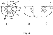
- a target 514 is illustrated which also allows for a quantitative assessment of the cutting accuracy without a direct perception of the length of a reference distance measure on the part of cut medium which is used for the assessment.
- the target 514 comprises four concentric circles 18 which may have a radius of 0.5 mm, 1 mm, 1.5 mm and 2 mm, respectively. In other examples, the radii may have any other values.
- the printed target 514 is centered with respect to two intended cutting lines 16, which intersect in the center of the target 514.
- Fig. 4b and 7c show two parts of cut medium which are selected from the parts which are obtained when cutting the medium 10, shown in Fig. 4a , along two perpendicular actual cutting lines 24.
- each cut along one of the actual cutting lines 24 has an error with respect to a corresponding parallel intended cutting line 16.
- the parts of Fig. 4b and 4c correspond to the portion at the bottom left and the portion at the bottom right, respectively, which are defined by the intersection of the actual cutting lines 24 in Fig. 4a .
- each of the rings 18 defines a corresponding reference distance measure and because at least some rings can be determined on the cut part, e.g. by counting the number of rings of a respective part a quantitative assessment can be performed. The number of rings can be counted starting with the outer ring or starting with the inner ring. From the part of Fig.
- the vertical cutting edge 26 intersects the second inner circle 18 having a radius of 1 mm but not the inner circle having a radius of 0.5 mm. Accordingly, the cutting error of the vertical cut 24 is between 0.5 mm and 1 mm.
- the part of Fig. 4c allows for an analogue assessment, deriving the same error for the vertical cut and an error of 1 mm for the horizontal cut, because the horizontal cutting edge 26 of Fig. 4c is a tangent of the second inner circle 18 of radius 1 mm.
- the target may comprise a mark 22, as shown in Fig. 2 .
- the mark 22 indicates the relative orientation of the target or a portion thereof with respect to the medium and/or the intended cutting lines.
- the horizontal line 20 of Fig. 2 may define an intended cutting line 16 and the medium 10 may be cut with a cutting error with respect to this intended cutting line 16 along an actual cutting line 24. Due to the cutting error, the cutting edge 26 may be above the horizontal line 20 of Fig. 2 or below this line 20, such that - with respect to the horizontal line 20 in Fig. 2 - an upper part of medium 10 will comprise the mark 22 and a lower part of medium 10 will not have any part of the mark 22 thereon. Accordingly, after the cutting process, both parts can be distinguished and identified as "upper" part comprising the mark 22 and "lower" part not comprising the mark 22.
- the part of the medium which includes the mark 22 comprises less/more than half of the target, it can be recognized that the actual cutting line 24 is shifted upwards/downwards with respect to the intended cutting line 16. If, on the other hand, after the cutting process, the part without the mark 22 comprises less/more than half of the target 14, it can be recognized that the actual cutting line 24 is shifted downwards/upwards with respect to the intended cutting line 16. Accordingly, based on the location of the mark 22, the direction of the cutting error can be determined with respect to the corresponding intended cutting line 16. If the intended cutting line 16 has a defined path relative to the medium 10, also the direction of the cutting error with respect to the medium 10 may be determined.
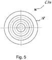
- Fig. 5 illustrates another example of a target 614 comprising seven concentric rings 18 having radii of 0.5 mm, 1 mm, 1.5 mm, 2 mm, 2.5 mm, 3 mm and 4 mm, respectively.
- the rings having the radii of 0.5 mm, 1.5 mm and 2.5 mm are printed using a brighter color than the other rings which enhances the readability when assessing the cutting accuracy.
- the graphical elements of a target may appear blurred or fuzzy due to a color miss-registration.
- the dispensing of different colorants may not be aligned. Therefore the visibility can be enhanced when the rings are printed by using just one colorant.
- Printers usually have the colorants cyan (C), magenta (M), yellow (Y) and black (K), such that just one of these colorants can be used.
- yellow is sometimes difficult to see on a bright medium and black may be mixed with other colorants (composite black), such that it might be challenging to control that only black ink is laid down during printing and such that the lines may appear soft. Therefore, one may chose cyan or magenta as colorant for printing the target for obtaining clear and visible targets.
- a spot color i.e. a color which is premixed rather than being mixed during printing, wherein the spot colors contain the same colorant but in a different amount. Because a spot color is not created by mixing different colorants during the printing process, color management during printing and colorant contamination can be avoided. For example, if a target is printed with cyan, a spot color of 100% cyan (dark cyan) and another spot color with 70% cyan (lighter cyan) can be used to print darker rings and lighter rings or other graphical elements, respectively. This can ensure that targets can be printed clear und sharp and are better readable.
- a target such as one of the targets of Figs. 1 to 7, is printed on a medium 10.
- at least one intended cutting line 16 is defined.
- the path of the intended cutting line 16 is defined with respect to the position and the orientation of the target.
- the path of the intended cutting line 16 is defined with respect to the medium 10.
- defining an intended cutting line 16 is performed after printing a target. In other examples, defining can be performed before printing.
- the medium can be cut 32 along an actual cutting line 24, wherein the path of the actual cutting line 24 may deviate from the path of the intended cutting line 16.
- the deviation corresponds to a cutting error.
- a portion of the cut medium may be optically inspected 34. This inspection may be performed visually by a person without using a measurement tool. In other examples, the inspection may be performed by an inspection device, for example by use of a scanning process. In a later stage, it can be assessed 36, whether there is a cutting error.
- the assessment may be qualitative and quantitative or may be quantitative, as explained with regard to Figs. 1 to 7.
- the target hence can be used for optically assessing the accuracy of cutting a medium along an intended cutting line, when the target is printed on the medium and comprises at least one graphical element which defines at least one reference distance measure.
- the target ca be centered at the intended cutting line or can be positioned at a defined distance from the intended cutting line.
Landscapes
- Treatment Of Fiber Materials (AREA)
- Handling Of Sheets (AREA)
- Control Of Cutting Processes (AREA)
Claims (12)
- Procédé comprenant :
la définition d'au moins une ligne de massicotage prévue (16) sur un support (10), la définition d'une cible (14, 114), la commande d'un moteur d'impression pour imprimer la cible sur le support (10), et dans lequel la cible comprend au moins un élément graphique (18) qui définit au moins une mesure de distance de référence et dans lequel la cible est centrée sur la ligne de massicotage prévue ou est positionnée à une distance définie de la ligne de massicotage prévue (16), l'au moins un élément graphique de la cible comprenant un anneau, qui est intersecté par l'au moins une ligne de massicotage prévue, un rayon de l'anneau correspondant à une mesure de distance de référence. - Procédé selon la revendication 1, comprenant en outrela découpe du support le long d'au moins une ligne de massicotage réelle, la ligne de massicotage réelle s'étendant à travers l'au moins un élément graphique de la cible, etla détermination d'une quantité d'un écart de la ligne de massicotage réelle par rapport à la ligne de massicotage prévue en inspectant optiquement au moins une pièce de la cible sur le support de découpe par rapport à la ligne de massicotage réelle.
- Procédé selon la revendication 1, comprenant la définition d'une première ligne de massicotage prévue et d'une seconde ligne de massicotage prévue, lesquelles première et seconde lignes de massicotage prévues sont perpendiculaires l'une à l'autre, la cible étant centrée ou positionnée à une distance définie par rapport à chacune des première et seconde lignes de massicotage prévues.
- Procédé selon la revendication 1, dans lequel la cible comprend un certain nombre d'anneaux concentriques ayant des rayons différents.
- Procédé selon la revendication 4, dans lequel deux lignes de massicotage prévues perpendiculaires coupant le centre des anneaux sont définies.
- Procédé selon la revendication 4, dans lequel les anneaux ont des rayons dans une plage comprise entre 0,5 mm et 4 mm.
- Procédé selon la revendication 1, dans lequel l'au moins un élément graphique est imprimé à l'aide d'un seul colorant.
- Procédé selon la revendication 1, dans lequel la cible comprend un certain nombre d'éléments graphiques qui sont imprimés à l'aide d'au moins deux couleurs d'accompagnement différentes contenant chacune une quantité différente d'un même colorant.
- Procédé selon la revendication 8, dans lequel la cible comprend un certain nombre d'éléments graphiques et au moins deux éléments graphiques différents sont imprimés à des luminosités différentes.
- Procédé selon la revendication 1, dans lequel la cible comprend en outre une marque indiquant l'orientation relative de la cible sur le support.
- Procédé selon la revendication 1, dans lequel l'anneau comprend une indication d'une valeur d'une mesure de distance de référence.
- Procédé d'évaluation optique de la précision de découpe d'un support (10) le long d'une ligne de massicotage prévue (16), dans lequel une cible (14, 114) est imprimée sur le support et dans lequel la cible comprend au moins un élément graphique (18) qui définit au moins une mesure de distance de référence etdans lequel la cible est centrée sur la ligne de massicotage prévue ou est positionnée à une distance définie de la ligne de massicotage prévue, dans lequel l'au moins un élément graphique de la cible comprend un anneau, qui est intersecté par l'au moins une ligne de massicotage prévue, un rayon de l'anneau correspondant à une mesure de distance de référence ;dans lequel le support est découpé le long d'une ligne de massicotage réelle (24), dans lequel le trajet de la ligne de massicotage réelle (24) peut s'écarter du trajet de la ligne de massicotage prévue (16) ; et une partie du support de découpe est inspectée optiquement et, dans une étape ultérieure, il est évalué s'il existe une erreur de découpe.
Applications Claiming Priority (1)
| Application Number | Priority Date | Filing Date | Title |
|---|---|---|---|
| PCT/EP2015/058388 WO2016165774A1 (fr) | 2015-04-17 | 2015-04-17 | Cible pour un procédé d'impression et de coupe |
Publications (2)
| Publication Number | Publication Date |
|---|---|
| EP3233503A1 EP3233503A1 (fr) | 2017-10-25 |
| EP3233503B1 true EP3233503B1 (fr) | 2022-06-22 |
Family
ID=52988060
Family Applications (1)
| Application Number | Title | Priority Date | Filing Date |
|---|---|---|---|
| EP15717165.3A Active EP3233503B1 (fr) | 2015-04-17 | 2015-04-17 | Cible pour un procédé d'impression et de coupe |
Country Status (4)
| Country | Link |
|---|---|
| US (1) | US10052890B2 (fr) |
| EP (1) | EP3233503B1 (fr) |
| CN (1) | CN107223087A (fr) |
| WO (1) | WO2016165774A1 (fr) |
Families Citing this family (7)
| Publication number | Priority date | Publication date | Assignee | Title |
|---|---|---|---|---|
| JP2018126891A (ja) * | 2017-02-07 | 2018-08-16 | コニカミノルタ株式会社 | 画像処理装置、画像形成装置、画像処理装置の制御プログラム、および画像形成装置の制御プログラム |
| US11520544B2 (en) | 2017-07-14 | 2022-12-06 | Georgia-Pacific Corrugated Llc | Waste determination for generating control plans for digital pre-print paper, sheet, and box manufacturing systems |
| US20190016551A1 (en) | 2017-07-14 | 2019-01-17 | Georgia-Pacific Corrugated, LLC | Reel editor for pre-print paper, sheet, and box manufacturing systems |
| US10642551B2 (en) | 2017-07-14 | 2020-05-05 | Georgia-Pacific Corrugated Llc | Engine for generating control plans for digital pre-print paper, sheet, and box manufacturing systems |
| US11449290B2 (en) | 2017-07-14 | 2022-09-20 | Georgia-Pacific Corrugated Llc | Control plan for paper, sheet, and box manufacturing systems |
| US11485101B2 (en) | 2017-07-14 | 2022-11-01 | Georgia-Pacific Corrugated Llc | Controls for paper, sheet, and box manufacturing systems |
| JP7327063B2 (ja) * | 2019-09-30 | 2023-08-16 | ブラザー工業株式会社 | 複合機 |
Citations (1)
| Publication number | Priority date | Publication date | Assignee | Title |
|---|---|---|---|---|
| CN1734316A (zh) * | 2004-08-10 | 2006-02-15 | 广辉电子股份有限公司 | 具有可目视切割精度的记号的液晶显示面板 |
Family Cites Families (18)
| Publication number | Priority date | Publication date | Assignee | Title |
|---|---|---|---|---|
| JP2605426B2 (ja) * | 1989-10-31 | 1997-04-30 | ブラザー工業株式会社 | 印刷装置 |
| DE69514016T2 (de) | 1994-02-28 | 2000-10-19 | Dynamotion/Abi Corp., Santa Ana | Bohrkoordinaten-Optimierung für mehrschichtige Leiterplatten |
| JP2000193950A (ja) * | 1998-12-28 | 2000-07-14 | Optrex Corp | Stn型液晶表示素子用干渉パネルの製造方法 |
| PT1321839E (pt) * | 2001-12-10 | 2007-04-30 | Lacent Technologies Inc | Sistema para cortar padrões pré-ajustados numa corrente contínua de material em folha |
| JP3963750B2 (ja) | 2002-03-25 | 2007-08-22 | 日本電産サンキョー株式会社 | 曲面切削加工方法 |
| US7059061B2 (en) | 2002-10-10 | 2006-06-13 | Don Gregory French | Framer's layout and cutting guide |
| CN2795200Y (zh) * | 2004-06-10 | 2006-07-12 | 上海广电液晶显示器有限公司 | 带有切割对位标记的玻璃 |
| US7478956B2 (en) * | 2004-10-14 | 2009-01-20 | Seiko Instruments Inc. | Printer for printing on both a heat-sensitive adhesive label and an ordinary label |
| US20070181027A1 (en) | 2005-10-14 | 2007-08-09 | Kyocera Mita Corporation | Misregistration judging method, registration mark for color printing, color slippage detection mark, color slippage correction chart, color registration correction chart color slippage detection method color slippage correction |
| JP4844531B2 (ja) * | 2007-10-26 | 2011-12-28 | ブラザー工業株式会社 | 印刷装置 |
| CN101844864B (zh) * | 2009-03-24 | 2013-08-28 | 北京京东方光电科技有限公司 | 玻璃基板及玻璃基板的切割方法 |
| JP5347785B2 (ja) * | 2009-07-13 | 2013-11-20 | セイコーエプソン株式会社 | 切断装置及び切断装置付きプリンター |
| CN102883850A (zh) * | 2010-05-14 | 2013-01-16 | 旭硝子株式会社 | 切割方法和切割装置 |
| JP5074563B2 (ja) * | 2010-07-29 | 2012-11-14 | 東芝テック株式会社 | カッターユニットおよびプリンタ |
| JP2012183671A (ja) | 2011-03-03 | 2012-09-27 | Toshiba Tec Corp | 印字装置およびその制御プログラム |
| US8924002B2 (en) | 2011-04-22 | 2014-12-30 | I-Cut, Inc. | Adaptive registration during precision graphics cutting from multiple sheets |
| JP5943642B2 (ja) * | 2012-02-24 | 2016-07-05 | 株式会社ジャパンディスプレイ | 立体表示装置 |
| CN104199208B (zh) * | 2014-09-05 | 2017-01-25 | 深圳晶华显示器材有限公司 | 一种带有对位切割标记的lcd显示面板及切割方法 |
-
2015
- 2015-04-17 EP EP15717165.3A patent/EP3233503B1/fr active Active
- 2015-04-17 CN CN201580075019.5A patent/CN107223087A/zh active Pending
- 2015-04-17 WO PCT/EP2015/058388 patent/WO2016165774A1/fr not_active Ceased
- 2015-04-17 US US15/547,738 patent/US10052890B2/en active Active
Patent Citations (1)
| Publication number | Priority date | Publication date | Assignee | Title |
|---|---|---|---|---|
| CN1734316A (zh) * | 2004-08-10 | 2006-02-15 | 广辉电子股份有限公司 | 具有可目视切割精度的记号的液晶显示面板 |
Also Published As
| Publication number | Publication date |
|---|---|
| CN107223087A (zh) | 2017-09-29 |
| US10052890B2 (en) | 2018-08-21 |
| EP3233503A1 (fr) | 2017-10-25 |
| US20180022118A1 (en) | 2018-01-25 |
| WO2016165774A1 (fr) | 2016-10-20 |
Similar Documents
| Publication | Publication Date | Title |
|---|---|---|
| EP3233503B1 (fr) | Cible pour un procédé d'impression et de coupe | |
| EP1575786B1 (fr) | Dispositif de mesure transparent dote de lignes plus visibles | |
| US4310248A (en) | Color control system | |
| TWI567366B (zh) | 具有增強觀察窗之透明量測裝置及形成一量測裝置之方法 | |
| US10878300B2 (en) | Adjusting a colour in an image | |
| JP6757517B2 (ja) | 目視確認支援装置及び目視確認支援方法 | |
| US11112311B2 (en) | Press operator target, LMD standard and colour proof assembly | |
| US6522993B1 (en) | Method and system for marking surface deviations on a three dimensional surface | |
| US7251898B2 (en) | Transparent measuring device with enhanced visibility lines | |
| ES2747252T3 (es) | Procedimiento para verificar una placa de impresión, especialmente un cilindro de huecograbado | |
| CN109605964A (zh) | 一种标准化的印刷控制方法 | |
| JP6852517B2 (ja) | 測色チャート作成装置、測色チャート作成方法、プログラム | |
| CN110440709A (zh) | 轮胎模具侧板的检查方法 | |
| US20230252669A1 (en) | Method for determining a reference position | |
| CN114211874B (zh) | 一种印刷的大面积颜色均匀性的检测方法 | |
| JPH03287350A (ja) | 鋼板 | |
| EP0476035B1 (fr) | Procede et systeme de commande de processus d'impression | |
| JP5290043B2 (ja) | トレッドカラーライン検査装置 | |
| EP3208089B1 (fr) | Barre de couleur intégrée et procédé d'impression | |
| JP2008541304A (ja) | 印刷画像の品質を測定するための方法および装置 | |
| CN217944612U (zh) | 一种胶印套印标记印版 | |
| JP6082686B2 (ja) | 印字検査方法 | |
| WO2017185141A1 (fr) | Procédé et système d'identification et de mesure d'un défaut qui réduit la transparence dans un substrat pour document de sécurité | |
| DE102009034236B4 (de) | Verfahren zum Kalibrieren von Farbmessgeräten | |
| CN119096268A (zh) | 用于检查钣金加工机器的图像处理系统的校准的方法 |
Legal Events
| Date | Code | Title | Description |
|---|---|---|---|
| STAA | Information on the status of an ep patent application or granted ep patent |
Free format text: STATUS: THE INTERNATIONAL PUBLICATION HAS BEEN MADE |
|
| PUAI | Public reference made under article 153(3) epc to a published international application that has entered the european phase |
Free format text: ORIGINAL CODE: 0009012 |
|
| STAA | Information on the status of an ep patent application or granted ep patent |
Free format text: STATUS: REQUEST FOR EXAMINATION WAS MADE |
|
| 17P | Request for examination filed |
Effective date: 20170720 |
|
| AK | Designated contracting states |
Kind code of ref document: A1 Designated state(s): AL AT BE BG CH CY CZ DE DK EE ES FI FR GB GR HR HU IE IS IT LI LT LU LV MC MK MT NL NO PL PT RO RS SE SI SK SM TR |
|
| AX | Request for extension of the european patent |
Extension state: BA ME |
|
| DAV | Request for validation of the european patent (deleted) | ||
| DAX | Request for extension of the european patent (deleted) | ||
| RAP1 | Party data changed (applicant data changed or rights of an application transferred) |
Owner name: HEWLETT-PACKARD DEVELOPMENT COMPANY, L.P. |
|
| STAA | Information on the status of an ep patent application or granted ep patent |
Free format text: STATUS: EXAMINATION IS IN PROGRESS |
|
| 17Q | First examination report despatched |
Effective date: 20200313 |
|
| GRAP | Despatch of communication of intention to grant a patent |
Free format text: ORIGINAL CODE: EPIDOSNIGR1 |
|
| STAA | Information on the status of an ep patent application or granted ep patent |
Free format text: STATUS: GRANT OF PATENT IS INTENDED |
|
| INTG | Intention to grant announced |
Effective date: 20220317 |
|
| GRAS | Grant fee paid |
Free format text: ORIGINAL CODE: EPIDOSNIGR3 |
|
| GRAA | (expected) grant |
Free format text: ORIGINAL CODE: 0009210 |
|
| STAA | Information on the status of an ep patent application or granted ep patent |
Free format text: STATUS: THE PATENT HAS BEEN GRANTED |
|
| AK | Designated contracting states |
Kind code of ref document: B1 Designated state(s): AL AT BE BG CH CY CZ DE DK EE ES FI FR GB GR HR HU IE IS IT LI LT LU LV MC MK MT NL NO PL PT RO RS SE SI SK SM TR |
|
| REG | Reference to a national code |
Ref country code: GB Ref legal event code: FG4D |
|
| REG | Reference to a national code |
Ref country code: CH Ref legal event code: EP |
|
| REG | Reference to a national code |
Ref country code: DE Ref legal event code: R096 Ref document number: 602015079539 Country of ref document: DE |
|
| REG | Reference to a national code |
Ref country code: AT Ref legal event code: REF Ref document number: 1499541 Country of ref document: AT Kind code of ref document: T Effective date: 20220715 |
|
| REG | Reference to a national code |
Ref country code: IE Ref legal event code: FG4D |
|
| REG | Reference to a national code |
Ref country code: LT Ref legal event code: MG9D |
|
| REG | Reference to a national code |
Ref country code: NL Ref legal event code: MP Effective date: 20220622 |
|
| PG25 | Lapsed in a contracting state [announced via postgrant information from national office to epo] |
Ref country code: SE Free format text: LAPSE BECAUSE OF FAILURE TO SUBMIT A TRANSLATION OF THE DESCRIPTION OR TO PAY THE FEE WITHIN THE PRESCRIBED TIME-LIMIT Effective date: 20220622 Ref country code: NO Free format text: LAPSE BECAUSE OF FAILURE TO SUBMIT A TRANSLATION OF THE DESCRIPTION OR TO PAY THE FEE WITHIN THE PRESCRIBED TIME-LIMIT Effective date: 20220922 Ref country code: LT Free format text: LAPSE BECAUSE OF FAILURE TO SUBMIT A TRANSLATION OF THE DESCRIPTION OR TO PAY THE FEE WITHIN THE PRESCRIBED TIME-LIMIT Effective date: 20220622 Ref country code: HR Free format text: LAPSE BECAUSE OF FAILURE TO SUBMIT A TRANSLATION OF THE DESCRIPTION OR TO PAY THE FEE WITHIN THE PRESCRIBED TIME-LIMIT Effective date: 20220622 Ref country code: GR Free format text: LAPSE BECAUSE OF FAILURE TO SUBMIT A TRANSLATION OF THE DESCRIPTION OR TO PAY THE FEE WITHIN THE PRESCRIBED TIME-LIMIT Effective date: 20220923 Ref country code: FI Free format text: LAPSE BECAUSE OF FAILURE TO SUBMIT A TRANSLATION OF THE DESCRIPTION OR TO PAY THE FEE WITHIN THE PRESCRIBED TIME-LIMIT Effective date: 20220622 Ref country code: BG Free format text: LAPSE BECAUSE OF FAILURE TO SUBMIT A TRANSLATION OF THE DESCRIPTION OR TO PAY THE FEE WITHIN THE PRESCRIBED TIME-LIMIT Effective date: 20220922 |
|
| REG | Reference to a national code |
Ref country code: AT Ref legal event code: MK05 Ref document number: 1499541 Country of ref document: AT Kind code of ref document: T Effective date: 20220622 |
|
| PG25 | Lapsed in a contracting state [announced via postgrant information from national office to epo] |
Ref country code: RS Free format text: LAPSE BECAUSE OF FAILURE TO SUBMIT A TRANSLATION OF THE DESCRIPTION OR TO PAY THE FEE WITHIN THE PRESCRIBED TIME-LIMIT Effective date: 20220622 Ref country code: LV Free format text: LAPSE BECAUSE OF FAILURE TO SUBMIT A TRANSLATION OF THE DESCRIPTION OR TO PAY THE FEE WITHIN THE PRESCRIBED TIME-LIMIT Effective date: 20220622 |
|
| PG25 | Lapsed in a contracting state [announced via postgrant information from national office to epo] |
Ref country code: NL Free format text: LAPSE BECAUSE OF FAILURE TO SUBMIT A TRANSLATION OF THE DESCRIPTION OR TO PAY THE FEE WITHIN THE PRESCRIBED TIME-LIMIT Effective date: 20220622 |
|
| PG25 | Lapsed in a contracting state [announced via postgrant information from national office to epo] |
Ref country code: SM Free format text: LAPSE BECAUSE OF FAILURE TO SUBMIT A TRANSLATION OF THE DESCRIPTION OR TO PAY THE FEE WITHIN THE PRESCRIBED TIME-LIMIT Effective date: 20220622 Ref country code: SK Free format text: LAPSE BECAUSE OF FAILURE TO SUBMIT A TRANSLATION OF THE DESCRIPTION OR TO PAY THE FEE WITHIN THE PRESCRIBED TIME-LIMIT Effective date: 20220622 Ref country code: RO Free format text: LAPSE BECAUSE OF FAILURE TO SUBMIT A TRANSLATION OF THE DESCRIPTION OR TO PAY THE FEE WITHIN THE PRESCRIBED TIME-LIMIT Effective date: 20220622 Ref country code: PT Free format text: LAPSE BECAUSE OF FAILURE TO SUBMIT A TRANSLATION OF THE DESCRIPTION OR TO PAY THE FEE WITHIN THE PRESCRIBED TIME-LIMIT Effective date: 20221024 Ref country code: ES Free format text: LAPSE BECAUSE OF FAILURE TO SUBMIT A TRANSLATION OF THE DESCRIPTION OR TO PAY THE FEE WITHIN THE PRESCRIBED TIME-LIMIT Effective date: 20220622 Ref country code: EE Free format text: LAPSE BECAUSE OF FAILURE TO SUBMIT A TRANSLATION OF THE DESCRIPTION OR TO PAY THE FEE WITHIN THE PRESCRIBED TIME-LIMIT Effective date: 20220622 Ref country code: CZ Free format text: LAPSE BECAUSE OF FAILURE TO SUBMIT A TRANSLATION OF THE DESCRIPTION OR TO PAY THE FEE WITHIN THE PRESCRIBED TIME-LIMIT Effective date: 20220622 Ref country code: AT Free format text: LAPSE BECAUSE OF FAILURE TO SUBMIT A TRANSLATION OF THE DESCRIPTION OR TO PAY THE FEE WITHIN THE PRESCRIBED TIME-LIMIT Effective date: 20220622 |
|
| PG25 | Lapsed in a contracting state [announced via postgrant information from national office to epo] |
Ref country code: PL Free format text: LAPSE BECAUSE OF FAILURE TO SUBMIT A TRANSLATION OF THE DESCRIPTION OR TO PAY THE FEE WITHIN THE PRESCRIBED TIME-LIMIT Effective date: 20220622 Ref country code: IS Free format text: LAPSE BECAUSE OF FAILURE TO SUBMIT A TRANSLATION OF THE DESCRIPTION OR TO PAY THE FEE WITHIN THE PRESCRIBED TIME-LIMIT Effective date: 20221022 |
|
| REG | Reference to a national code |
Ref country code: DE Ref legal event code: R097 Ref document number: 602015079539 Country of ref document: DE |
|
| PG25 | Lapsed in a contracting state [announced via postgrant information from national office to epo] |
Ref country code: AL Free format text: LAPSE BECAUSE OF FAILURE TO SUBMIT A TRANSLATION OF THE DESCRIPTION OR TO PAY THE FEE WITHIN THE PRESCRIBED TIME-LIMIT Effective date: 20220622 |
|
| PG25 | Lapsed in a contracting state [announced via postgrant information from national office to epo] |
Ref country code: DK Free format text: LAPSE BECAUSE OF FAILURE TO SUBMIT A TRANSLATION OF THE DESCRIPTION OR TO PAY THE FEE WITHIN THE PRESCRIBED TIME-LIMIT Effective date: 20220622 |
|
| PLBE | No opposition filed within time limit |
Free format text: ORIGINAL CODE: 0009261 |
|
| STAA | Information on the status of an ep patent application or granted ep patent |
Free format text: STATUS: NO OPPOSITION FILED WITHIN TIME LIMIT |
|
| 26N | No opposition filed |
Effective date: 20230323 |
|
| PG25 | Lapsed in a contracting state [announced via postgrant information from national office to epo] |
Ref country code: SI Free format text: LAPSE BECAUSE OF FAILURE TO SUBMIT A TRANSLATION OF THE DESCRIPTION OR TO PAY THE FEE WITHIN THE PRESCRIBED TIME-LIMIT Effective date: 20220622 |
|
| REG | Reference to a national code |
Ref country code: DE Ref legal event code: R119 Ref document number: 602015079539 Country of ref document: DE |
|
| REG | Reference to a national code |
Ref country code: CH Ref legal event code: PL |
|
| GBPC | Gb: european patent ceased through non-payment of renewal fee |
Effective date: 20230417 |
|
| PG25 | Lapsed in a contracting state [announced via postgrant information from national office to epo] |
Ref country code: LU Free format text: LAPSE BECAUSE OF NON-PAYMENT OF DUE FEES Effective date: 20230417 |
|
| REG | Reference to a national code |
Ref country code: BE Ref legal event code: MM Effective date: 20230430 |
|
| PG25 | Lapsed in a contracting state [announced via postgrant information from national office to epo] |
Ref country code: MC Free format text: LAPSE BECAUSE OF FAILURE TO SUBMIT A TRANSLATION OF THE DESCRIPTION OR TO PAY THE FEE WITHIN THE PRESCRIBED TIME-LIMIT Effective date: 20220622 |
|
| PG25 | Lapsed in a contracting state [announced via postgrant information from national office to epo] |
Ref country code: GB Free format text: LAPSE BECAUSE OF NON-PAYMENT OF DUE FEES Effective date: 20230417 |
|
| PG25 | Lapsed in a contracting state [announced via postgrant information from national office to epo] |
Ref country code: MC Free format text: LAPSE BECAUSE OF FAILURE TO SUBMIT A TRANSLATION OF THE DESCRIPTION OR TO PAY THE FEE WITHIN THE PRESCRIBED TIME-LIMIT Effective date: 20220622 Ref country code: LI Free format text: LAPSE BECAUSE OF NON-PAYMENT OF DUE FEES Effective date: 20230430 Ref country code: IT Free format text: LAPSE BECAUSE OF FAILURE TO SUBMIT A TRANSLATION OF THE DESCRIPTION OR TO PAY THE FEE WITHIN THE PRESCRIBED TIME-LIMIT Effective date: 20220622 Ref country code: GB Free format text: LAPSE BECAUSE OF NON-PAYMENT OF DUE FEES Effective date: 20230417 Ref country code: FR Free format text: LAPSE BECAUSE OF NON-PAYMENT OF DUE FEES Effective date: 20230430 Ref country code: DE Free format text: LAPSE BECAUSE OF NON-PAYMENT OF DUE FEES Effective date: 20231103 Ref country code: CH Free format text: LAPSE BECAUSE OF NON-PAYMENT OF DUE FEES Effective date: 20230430 |
|
| REG | Reference to a national code |
Ref country code: IE Ref legal event code: MM4A |
|
| PG25 | Lapsed in a contracting state [announced via postgrant information from national office to epo] |
Ref country code: BE Free format text: LAPSE BECAUSE OF NON-PAYMENT OF DUE FEES Effective date: 20230430 |
|
| PG25 | Lapsed in a contracting state [announced via postgrant information from national office to epo] |
Ref country code: IE Free format text: LAPSE BECAUSE OF NON-PAYMENT OF DUE FEES Effective date: 20230417 |
|
| PG25 | Lapsed in a contracting state [announced via postgrant information from national office to epo] |
Ref country code: IE Free format text: LAPSE BECAUSE OF NON-PAYMENT OF DUE FEES Effective date: 20230417 |
|
| PG25 | Lapsed in a contracting state [announced via postgrant information from national office to epo] |
Ref country code: BG Free format text: LAPSE BECAUSE OF FAILURE TO SUBMIT A TRANSLATION OF THE DESCRIPTION OR TO PAY THE FEE WITHIN THE PRESCRIBED TIME-LIMIT Effective date: 20220622 |
|
| PG25 | Lapsed in a contracting state [announced via postgrant information from national office to epo] |
Ref country code: BG Free format text: LAPSE BECAUSE OF FAILURE TO SUBMIT A TRANSLATION OF THE DESCRIPTION OR TO PAY THE FEE WITHIN THE PRESCRIBED TIME-LIMIT Effective date: 20220622 |
|
| PG25 | Lapsed in a contracting state [announced via postgrant information from national office to epo] |
Ref country code: CY Free format text: LAPSE BECAUSE OF FAILURE TO SUBMIT A TRANSLATION OF THE DESCRIPTION OR TO PAY THE FEE WITHIN THE PRESCRIBED TIME-LIMIT; INVALID AB INITIO Effective date: 20150417 |
|
| PG25 | Lapsed in a contracting state [announced via postgrant information from national office to epo] |
Ref country code: HU Free format text: LAPSE BECAUSE OF FAILURE TO SUBMIT A TRANSLATION OF THE DESCRIPTION OR TO PAY THE FEE WITHIN THE PRESCRIBED TIME-LIMIT; INVALID AB INITIO Effective date: 20150417 |
|
| PG25 | Lapsed in a contracting state [announced via postgrant information from national office to epo] |
Ref country code: TR Free format text: LAPSE BECAUSE OF FAILURE TO SUBMIT A TRANSLATION OF THE DESCRIPTION OR TO PAY THE FEE WITHIN THE PRESCRIBED TIME-LIMIT Effective date: 20220622 |