EP3233634B1 - Corps remorqué actif de forme aérodynamique - Google Patents
Corps remorqué actif de forme aérodynamique Download PDFInfo
- Publication number
- EP3233634B1 EP3233634B1 EP15831127.4A EP15831127A EP3233634B1 EP 3233634 B1 EP3233634 B1 EP 3233634B1 EP 15831127 A EP15831127 A EP 15831127A EP 3233634 B1 EP3233634 B1 EP 3233634B1
- Authority
- EP
- European Patent Office
- Prior art keywords
- fuselage
- towed
- towed body
- towed element
- control device
- Prior art date
- Legal status (The legal status is an assumption and is not a legal conclusion. Google has not performed a legal analysis and makes no representation as to the accuracy of the status listed.)
- Active
Links
Images


Classifications
-
- B—PERFORMING OPERATIONS; TRANSPORTING
- B64—AIRCRAFT; AVIATION; COSMONAUTICS
- B64D—EQUIPMENT FOR FITTING IN OR TO AIRCRAFT; FLIGHT SUITS; PARACHUTES; ARRANGEMENT OR MOUNTING OF POWER PLANTS OR PROPULSION TRANSMISSIONS IN AIRCRAFT
- B64D3/00—Aircraft adaptations to facilitate towing or being towed
- B64D3/02—Aircraft adaptations to facilitate towing or being towed for towing targets
-
- B—PERFORMING OPERATIONS; TRANSPORTING
- B64—AIRCRAFT; AVIATION; COSMONAUTICS
- B64C—AEROPLANES; HELICOPTERS
- B64C3/00—Wings
- B64C3/10—Shape of wings
- B64C3/16—Frontal aspect
-
- B—PERFORMING OPERATIONS; TRANSPORTING
- B64—AIRCRAFT; AVIATION; COSMONAUTICS
- B64C—AEROPLANES; HELICOPTERS
- B64C39/00—Aircraft not otherwise provided for
- B64C39/02—Aircraft not otherwise provided for characterised by special use
- B64C39/022—Tethered aircraft
-
- B—PERFORMING OPERATIONS; TRANSPORTING
- B64—AIRCRAFT; AVIATION; COSMONAUTICS
- B64U—UNMANNED AERIAL VEHICLES [UAV]; EQUIPMENT THEREFOR
- B64U10/00—Type of UAV
- B64U10/25—Fixed-wing aircraft
-
- B—PERFORMING OPERATIONS; TRANSPORTING
- B64—AIRCRAFT; AVIATION; COSMONAUTICS
- B64U—UNMANNED AERIAL VEHICLES [UAV]; EQUIPMENT THEREFOR
- B64U10/00—Type of UAV
- B64U10/50—Glider-type UAVs, e.g. with parachute, parasail or kite
-
- B—PERFORMING OPERATIONS; TRANSPORTING
- B64—AIRCRAFT; AVIATION; COSMONAUTICS
- B64U—UNMANNED AERIAL VEHICLES [UAV]; EQUIPMENT THEREFOR
- B64U10/00—Type of UAV
- B64U10/60—Tethered aircraft
-
- B—PERFORMING OPERATIONS; TRANSPORTING
- B64—AIRCRAFT; AVIATION; COSMONAUTICS
- B64U—UNMANNED AERIAL VEHICLES [UAV]; EQUIPMENT THEREFOR
- B64U30/00—Means for producing lift; Empennages; Arrangements thereof
- B64U30/10—Wings
-
- B—PERFORMING OPERATIONS; TRANSPORTING
- B64—AIRCRAFT; AVIATION; COSMONAUTICS
- B64U—UNMANNED AERIAL VEHICLES [UAV]; EQUIPMENT THEREFOR
- B64U30/00—Means for producing lift; Empennages; Arrangements thereof
- B64U30/40—Empennages, e.g. V-tails
-
- F—MECHANICAL ENGINEERING; LIGHTING; HEATING; WEAPONS; BLASTING
- F41—WEAPONS
- F41J—TARGETS; TARGET RANGES; BULLET CATCHERS
- F41J9/00—Moving targets, i.e. moving when fired at
- F41J9/08—Airborne targets, e.g. drones, kites, balloons
- F41J9/10—Airborne targets, e.g. drones, kites, balloons towed
-
- B—PERFORMING OPERATIONS; TRANSPORTING
- B64—AIRCRAFT; AVIATION; COSMONAUTICS
- B64C—AEROPLANES; HELICOPTERS
- B64C1/00—Fuselages; Constructional features common to fuselages, wings, stabilising surfaces or the like
- B64C2001/0045—Fuselages characterised by special shapes
-
- B—PERFORMING OPERATIONS; TRANSPORTING
- B64—AIRCRAFT; AVIATION; COSMONAUTICS
- B64U—UNMANNED AERIAL VEHICLES [UAV]; EQUIPMENT THEREFOR
- B64U2201/00—UAVs characterised by their flight controls
- B64U2201/10—UAVs characterised by their flight controls autonomous, i.e. by navigating independently from ground or air stations, e.g. by using inertial navigation systems [INS]
-
- B—PERFORMING OPERATIONS; TRANSPORTING
- B64—AIRCRAFT; AVIATION; COSMONAUTICS
- B64U—UNMANNED AERIAL VEHICLES [UAV]; EQUIPMENT THEREFOR
- B64U2201/00—UAVs characterised by their flight controls
- B64U2201/20—Remote controls
-
- B—PERFORMING OPERATIONS; TRANSPORTING
- B64—AIRCRAFT; AVIATION; COSMONAUTICS
- B64U—UNMANNED AERIAL VEHICLES [UAV]; EQUIPMENT THEREFOR
- B64U80/00—Transport or storage specially adapted for UAVs
- B64U80/80—Transport or storage specially adapted for UAVs by vehicles
- B64U80/82—Airborne vehicles
Definitions
- the invention relates to an aerodynamically shaped, active towed body, which is towable by a tow from a powered aircraft through the air, at least with a vaulted in its vertical and horizontal longitudinal plane fuselage with an aggregate chamber in which at least one power supply and a control device arranged are, and a load chamber and arranged with two arranged in the rear of the fuselage wings and a tail fin with each adjustable by the controller oars and with a coupling for the tow.
- Such towed bodies are used on the one hand in the military field, where they are used for training purposes as targets or distractions from the aircraft. On the other hand, however, towed bodies are also used in the civilian sector for different measuring purposes.
- a powered aircraft usually an aircraft or a helicopter
- the atmospheric boundary layer to 300 m by occurring natural and man-made obstacles is severely limited.
- Under good visibility conditions no deep clouds or cloudless
- poor visibility conditions low clouds, fog, rain, etc.
- unmanned towed bodies are used, which do not have their own propulsion (as opposed to drones), but are towed through the air by the aircraft, which then flies in a noncritical altitude zone above 300 m.
- the general direction of flight of the towed body is thus determined by the aircraft.
- the towed body is connected to the towed body via a tow rope that is variable in length.
- passive towed bodies which do not possess their own maneuverability
- active towed bodies which have their own maneuverability in space within the general flight direction prescribed by the aircraft.
- Towing bodies for measurement purposes are used, for example, in the polar regions to obtain information about the sea ice surface and thickness distribution.
- atmospheric measurements can be carried out with such trailing bodies (for example measurements of the content of BC BlackCarbon, aerosol measurements (particle concentrations, chemical composition) and atmospheric trace gas measurements (CO, CO 2 , SO 2 , NO X ) to obtain information about the meteorological conditions and the nature of the clouds, geophysical prospecting and environmental monitoring (emissions from ships and power plants and landmine detection) in accessible settlement or industrial areas, but also in particularly inaccessible areas (polar areas, oceans, mountains, rainforests, deserts)).
- flying height of the towed body can be measured at a height (flying height of the towed body) or synchronously at two heights (flight levels of the flying machine and towed body) within or simultaneously inside and outside the planetary boundary layer.
- vertical measuring profiles can be used in different ways Flying heights are determined to be close to the ground in good visibility conditions, without having to change the towing length.
- An active towed body for measurement purposes is from the presentation "Measurements of Air-Sea Fluxes with a Controlled Towed Vehicle (CTV)" by D. Khelif et al. known.
- the presentation was published as part of the Ocean Sciences Meeting of the UNOLS Scientific Committee for Oceanographic Aircraft Research at the Town Hall Session, Portland, Oregon, USA, on February 22, 2010, and is available on the Internet (as of 19/11/2014) at URL http: //www.unols.org/sites/default/files/201002scoap_09.pdf.
- the known CTV is a partially active towed body for non-contact determination of measured data from the airspace.
- the towed body has various sensors for the determination of measured data, such as meteorological sensors (pressure and temperature sensor, hygrometer and anemometer and sensors for trace gas measurements) and to determine its position in the air, such as radar-based altimeter, GPS system, navigation system and video camera.
- meteorological sensors pressure and temperature sensor, hygrometer and anemometer and sensors for trace gas measurements
- the towed body has two short wings, which are rotatable about a radial axis and serve to change the height of the towed body in flight.
- the known towed body is cylindrical and thus aerodynamically unfavorable. For flight stabilization, the known towed body therefore has a plurality of rigid wind deflectors.
- the known towed body has a computer-aided control device, which has an automatic flight control system for automatic control of the vertical flight position (altitude) of the towed body.
- an automatic flight control system for automatic control of the vertical flight position (altitude) of the towed body.
- the closest prior art to the invention is known from GB 737 318 A known. It describes an active towed body as an air target for military purposes, which can be towed by a tow from an aircraft through the air.
- the towed body has an aerodynamic design and has a curved hull in both the vertical and the horizontal longitudinal plane (in which the longitudinal axis x lies). The result is a torpedo-like, rotationally symmetrical hull.
- the towed body has two wings and at its rear a tail fin. The wings are delta-shaped in their view and run completely flat in their cross section. The wings are centered at a right angle to the fuselage (in towing mode, they are horizontal in a straight line flight).
- the wings In the supervision of the wings are arranged in the rear of the fuselage.
- the known towed body is active, ie formed maneuverable and can be directed in all three spatial directions.
- the wings have rotatable wing ends (corresponding to ailerons), over which a curve inclination of the towed body can be achieved.
- elevator are integrated into the wings and a rudder in the tail fin. All rudders are controlled by a control device which is arranged in an aggregate chamber in the fuselage.
- the control device is operated manually from the aircraft, remotely controlled by a ground station or by autopilot from the towed body, the autopilot is used to stabilize the position of the towed body in towing mode.
- the power supply for the towed body in the form of accumulators is located in the aggregate chamber.
- the aggregate chamber of the known towed body is made of solid material and has corresponding recesses for the control device and the energy supply.
- the hull still includes a load chamber, which is completely filled by a parachute.
- the tow rope is attached to a coupling attached detachable humpback nose of the towed body. By breaking off the hump nose, the towed body can be decoupled from the aircraft. Due to its aerodynamic shape of the tow body has sliding properties and can be landed with the help of the parachute.
- bent wings There are also known from the prior art bent wings for different missiles known. This principle of the so-called "gull wing” (gull wing) has several advantages and gives an aircraft especially in cornering a higher lateral stability. So it is from the DE 424 378 A and the DE 196 52 414 A1 known to bend the wings to stabilize an aircraft. However, the wings are arranged laterally or above the fuselage and initially bend upwards. The displacement effect by the air flowing upwards laterally increases the stability of the aircraft, but also results in less buoyancy.
- a towed body in which the wings are arranged below the fuselage with a circular cross-section and initially run obliquely downwards, before they then bend obliquely upwards.
- the kinked wings should but above all form a catching funnel for a cable, which is to be coupled in the air to the towed body to catch up with this.
- 6,765,383 B1 known towed body for measurement tasks is also passive and formed with a double-curved hull and has a nasal mast in which various measuring instruments or their sensors are arranged. From the DE 199 16 145 A1 It is known to assemble the wings of an aircraft to increase the buoyancy and to stabilize the flight behavior in each case from a plurality of segments. However, these are downwardly open flow chambers with narrowing cross-section.
- the older registration DE 10 2014 001 873 A1 also deals with a manoeuvrable, active tow body for scientific and commercial measurement and based on the CTV described above.
- the towed body of the prior application achieves full maneuverability throughout the space.
- the automated autonomous flying around of detected obstacles already represents a relevant safety aspect in the towed body claimed in the earlier application, which relieves the pilots of the aircraft significantly.
- It is in the older application not the aerodynamic design of the towed body with an optimized load bearing in the foreground, but the ability to reliably transfer the towed body by means of an electro-mechanical malfunction module in a flight-neutral position in case of failure or failure of the control electronics to him safely through to be able to recover the aircraft.
- the present application relates to other aspects than the earlier application, but with respect to the other, general facts expressly assumes its scope of disclosure.
- the object of the present invention is to develop this generic towed body so that it can be used for scientific and commercial measurement purposes and with a large and variable load, especially in the form of measuring instruments with associated sensors, easy loading.
- he should maintain and even improve his full maneuverability in space and its aerodynamic properties.
- the drag body according to the invention should also be able to slide safely in the straight-ahead flight, despite its load, and in the uncoupled state.
- the solution according to the invention for this task can be found in claim 1.
- the towed body according to the invention is characterized in that the fuselage is triangular in its transverse plane, with two upper corners on the upper side of the fuselage and one lower corner on the lower side of the fuselage, and the fuselage arching in its vertical longitudinal plane only on the upper side and straight on the underside, and each of the two wings is divided into a small and a large segment, with the small segment pointing downwards in the lower corner on the fuselage and the large segment pointing upwards adjoining the small segment, and each small segment has a further load chamber.
- the hull of the towed body according to the invention is aerodynamically shaped in a special way. In its horizontal longitudinal plane it is symmetrically curved. In its vertical longitudinal plane, however, it is curved only on its upper side, whereas its underside is not arched. This results in a particularly well-powered and aerodynamically optimized shape, but at the same time provides a comfortable interior for accommodating loads available. Furthermore, in the triangular shape of the transverse plane of the fuselage of the towed body, the upper side of the fuselage has a broad surface and the underside of the fuselage has a narrow surface. The loads can be well placed in the hull from above as well as from the side. In the introduced loads in the hull can be seen well from above. The triangular cross-sectional shape of the fuselage also results in a good self-retention of the load introduced, since the load is self-centering aligned with the lowest point of the fuselage. Slipping during towing is excluded.
- the wings of the towed body according to the invention engage laterally in the lower region of the hull, ie in its narrow region on its underside.
- the wing length is extended in relation to a wing engaging laterally in the middle on a bulging hull, without increasing the span between the wing tips.
- the flight characteristics of the towed body are improved, without deteriorating its manageability.
- Each wing is divided into two sections and consists of a small and a large segment. The small segments are pointing downwards, ie downwards. In the space underneath and below the fuselage, an air cushion forms during flight, which carries and stabilizes the towed body.
- the large segments of the wings adjoining the small segments are pointing upwards, ie upwards, so that the air can flow upwards. Due to the resulting displacement effect, the stability of the towed body is further increased.
- pointing downwards is meant the area below the towed body and “pointing upwards” (upwards) means the area above the towed body when it is in towing mode in its active orientation.
- the angles of incidence of the small and large segments are different, in particular, the small segments may be shallower down than the large segments are facing upwards.
- the small segments of the wings are made thicker than the large segments, which are slim and tapered. The thicker design of the small segments creates space for additional load in the wings in the form of additional load chambers. As a result, the entire payload of the towed body, which is now composed of the payload in the load chamber in the fuselage and the payload in the other load chambers in the small segments of the wings, still increased.
- a rudder for the attitude control about the longitudinal axis (x-axis) and the transverse axis (Y-axis) of the towed body and in the tail fin a rudder for the attitude control to the Vertical axis (z-axis) of the towed body is arranged.
- the rudders are integrated as wing flaps in the wings. Verschwenkept in the third spatial axis (z-axis) are in the claimed towed body on the Rudder reached in the tailfin. Overall, there is a V-shaped tail with only two oars.
- the towed body according to the invention is fully manoeuvrable in space and can avoid obstacles in particular automatically or remotely controlled.
- the control device comprises an autopilot control device and a manual control device, wherein the autopilot control device also comprises a position-stabilizing gyro system and an anticollision module. Due to the autopilot control device, the claimed towed body can independently avoid obstacles. This is particularly advantageous if the operators do not have direct visual contact with the towed body in the sluggish aircraft, for example if the aircraft is flying above and the towed body is flying below the cloud cover or if the distance between the aircraft and the towed body is very large.
- an anti-collision module For the independent evasion of the towed body, an anti-collision module is used, which detects obstacles via forward-looking measuring sensors and forwards their data to the autopilot control device, which converts these data into corresponding control commands to the rudders. This ensures optimal avoidance of the towed body against obstacles by combined changes in its vertical and lateral attitude. Above all, this allows a very low flying over of the ground in the area of obstacles (5m - 10m above the surface). Due to the precise positioning of the towed body relative to the ground, it can also be used at altitudes with special wind regimes, in low clouds and in complex terrain where otherwise strong conditions exist or operations of a towed body are not possible at all.
- the flight of the towed body For the determination of measured data, it is important to stabilize the flight of the towed body in order to be able to make exact statements about the respective attitude of the towed body in relation to the measured data or to be able to carry out measurements which require a constant distance between the towed body and the aircraft (for example, far-infrared spectroscopy).
- the claimed towed body therefore has a gyro system (gyro system), with its data, the autopilot control device via the control of the rudder steadily stabilized the towed body in its attitude. Due to the gyroscope, which can be redundant to increase safety, oscillations of the towed body when towing, but also when lifting and Fieren be compensated immediately.
- the towed body remains in straight flight in a stable attitude and does not lurch. However, the gyro system can also be overridden manually.
- the proportion between automatic and manual control is adjustable.
- the towed body can be maneuvered via the manual control device, for example, to exact height changes of the towed body for measuring height profiles or exact positioning of the towed body in relation to an object, such as the exhaust cloud of a cargo or cruise ship, bring about.
- the communication between aircraft and towed body preferably takes place via a wireless radio link.
- the personnel on board the aircraft may, for example, be equipped with shutter glasses and a predictive video system (first person view).
- the shutter glasses allow an operator to perceive the view from his aircraft and from or onto the towed body alternately or simultaneously and then communicate accordingly with the pilot to control the aircraft and the towed body.
- the towed body according to the invention is not intended for military use and has its main field of application in the field of metrology. He maneuvers the tow rope and / or steered away from the aircraft or steered away from the ground or independently. Measurement data are needed for the later evaluation as well as for the current flight operation.
- For the claimed towed body must be able to absorb relatively large loads in the form of measuring instruments of various kinds. For commercialization, it is also particularly important that the loads can be easily picked up and removed. Preferred and advantageous it Therefore, when the wings and the aggregate chamber in the rear of the towed body and the load chamber in the middle and front of the towed body are arranged.
- the aggregate chamber accommodates those loads that are permanently on board the towed body and serve to maneuver and supply it and to supply the measuring instruments. Although these loads must also be maintained, they always remain with every use in the towed body. Therefore, they may be located at a less accessible location of the towed body. By contrast, access to the variable payloads should be largely unhindered and particularly easy. Therefore located in the claimed towed body, the load chamber in the middle and front part of the fuselage, which is more accessible. The other load chambers in the small segments of the wings are also easily accessible.
- the load chamber in the fuselage has individually removable segment chambers which can be loaded with variable payloads.
- the segment chambers can be pre-equipped by the users and then simply installed and removed in the towed body.
- a modular system with differently equipped segment chambers, which are selected and combined according to requirements, can be implemented.
- the segment chambers may be simply cuboid. But you can also be adapted to the triangular hull in its outer contour, resulting in a secure determination and optimum space utilization in the fuselage. It is particularly advantageous and preferred when the upper corners and the lower corner of the fuselage are rounded.
- the result is a continuous triangular shape in the transverse plane, which is particularly aerodynamic to the outside and particularly load-friendly to the inside. Dead spaces through sharp corners are avoided. In addition, disturbing turbulence vortices are avoided on the outer skin of the fuselage.
- a nasal mast is arranged, in which at least one measuring instrument and / or a transmitting and Receiving device, which is the wireless connection to the powered aircraft and / or to a ground or water-based receiving and transmitting station housed. Due to the central coupling, the maneuverability of the towed body is increased even further compared to a towed body towed on the nose. At the same time the nose of the towed body is free for the attachment and accommodation of other measuring instruments.
- the nasal pole upstream of the nasal tip protrudes unobstructed and freely into the room and can therefore be used well for observational observations and measurements as well as for radio communication and data transfer.
- the load space already lying in front of the hull in the claimed towed body is thereby widened even beyond the nose of the towed body.
- the transceivers are available for direct measurement data transmission to different stations, but also for remote control of the towed body from different stations.
- the transmission channels can be used in both directions (bidirectional).
- a particular advantage of the claimed towed body can be seen in its large load capacity and advantageous load arrangement and segmentation, but due to the special design of the fuselage and the wings still does not reduce its particularly good aerodynamic flight characteristics, in particular gliding flight characteristics. Due to the main field of application, the use of measurement technology in all variations, it is advantageous and preferred if in the load chamber in the hull and in the other load chambers in the small segments of each wing different measuring instruments are arranged.
- the large load chamber in the fuselage is particularly suitable for heavier gauges that do not necessarily need the forward-looking flight direction of the towed body, as it does For example, in imaging devices is the case.
- the other load chambers in the small segments of the wings have a forward-looking position.
- Gas and / or aerosol inlet nozzles for measuring instruments can therefore be arranged particularly advantageously in the further load chambers of the small segments, for example for carrying out trace gas or particle measurements.
- the measuring instruments at least a forward-looking infrared camera system, a video camera system, a laser-based distance measuring system (to ensure minimum distances of the towed body both forward and downward), a radar-based altitude measuring system, a satellite-based location system and / or a measuring system for meteorological parameters, such as temperature, humidity and wind.
- a swivel video camera in the aircraft This can in particular observe the towed body and display on a well-visible for the pilot in the aircraft display. Together with the FPV, the towed body can be monitored externally and with an internal view from the aircraft or from other stations.
- the aggregate space of the claimed towed body absorbs mainly such control devices that are required for towing, whereas the load space is mainly reserved for measuring instruments for research and research purposes.
- the power supply for the various measuring instruments and control devices on board preferably comprises accumulators and a generator for charging the accumulators during towing operation.
- the accumulators which may advantageously be powerful and durable lithium polymer accumulators, are preferably arranged in the aggregate space.
- the generator can preferably and advantageously be designed as a brushless generator whose outer rotor is designed in the form of a deployable propeller and arranged at the rear of the fuselage, wherein the propeller is driven in tow mode by the air flow.
- the generator is therefore advantageously arranged at the fuselage end, in which the aggregate space is located in the claimed towed body.
- a rescue parachute system is arranged in the hull of the towed body.
- a rescue parachute is activated, which supports an automatic or manual rescue.
- a decoupling of the towed body from the aircraft is usually only in an emergency, for example, when a flying around a sudden emerging obstacle is no longer possible or necessary functions in the towed body or the entire power supply have failed.
- the emergency parachute system can be located both in the aggregate chamber at the rear end of the fuselage and in the load chamber in the front or middle part of the fuselage or in the further load chamber in the small segments of the wings of the fuselage Be arranged towed body. It then has a correspondingly positioned ejection opening.
- FIG. 1 is in the overall perspective view of a towed body 01 according to the invention in active and aerodynamically shaped training shown (Cartesian coordinate system x: longitudinal axis, y: transverse axis, z: vertical axis).
- the towed body 01 has a fuselage 02, two deltaförmige in the plan Wings 03 and a tail fin 04 on.
- the hull 02 may be made of a plastic, for example carbon fiber reinforced, but also made of a light metal material.
- the wings 03 are each divided into a small segment 07 and a large segment 08.
- the small segment 07 and the large segment 08 are arranged at an angle to each other, resulting in a crease line 33, further embodiments are the description of FIG. 2 refer to.
- an aggregate chamber 09 in the rear region of the fuselage 02 and a load chamber 10 in the middle and front region of the fuselage 02 are present.
- the towed body 01 has a nose mast 14 in which also measuring instruments 12 and / or transmitting and receiving devices 32 are located. It can be seen in the FIG. 1 also a centrally arranged detachable coupling 30 for a tow rope 31 .
- the towed body 01 is shown in front view.
- the triangular transverse plane 15 (yz plane) of the fuselage 02 with its two upper corners 16 and its lower corner 17 can be seen. Shown are rounded corners 16, 17. Between the two upper corners 16 a wide top 18 of the fuselage 02 is formed. In the area of the lower corner 17 , a tapered underside 19 is formed. In the area of the lower corner 17 , the two small segments 07 of the wings 03 are arranged pointing downwards. At the small segments 07 close the big ones Segments 08 of the wings 03 pointing upward. It results in each wing 03 aerodynamically favorable kink 20.
- the small segments 07 and the large segments 08 are arranged at different angles.
- the small segments 07 point flatter down as the large segments 08 rise upward. Shown are also the trace gas and / or Aerosoleinlassdüsen 13, the nose pole 14 and the tail fin 04. Also indicated is the load space 10, executed in the embodiment shown rectangular and adapted to the transverse plane 15 of the fuselage 02 .
- the load space 10 is loaded with measuring instruments 12 .
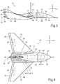
- FIG. 3 shows the towed body 01 in the side view (not mentioned reference numerals are shown in the preceding figures).
- a curvature 21 of the top 18 of the fuselage 02 whereas the bottom 19 of the fuselage 02 is not curved and flat.
- a small segment 07 and a large segment 08 with the rudder 05 of a wing 03 are shown.
- the tail fin 04 with the rudder 06 can be seen.
- the load space 10 in the front and middle regions of the fuselage 02 , the nose mast 14 and a trace gas or aerosol inlet nozzle 13 are indicated.
- the load space 10 is rectangular and divided into individual segment chambers 22 .
- the individual segment chambers 22 are various measuring instruments 12.
- a folding propeller 26 may be arranged, which drives a generator for charging the batteries.
- FIG. 4 shows in the towed body 01 in plan view. Shown is a symmetrical curvature 23 in the horizontal longitudinal plane (xy plane) of the fuselage 02. Good to see the pointed inlet of the fuselage 02 to its rear 34 back. Both constructive measures support the aerodynamics of the towed body 01 .
- the configuration of the small segments 07 and the large segments 08 of the wings 03 is also clearly visible.
- the large segments 08 are servo drives 24 for the rudders 05 indicated.
- the small segments 07 include the other load chambers 11. In the plan view is easy to see how the other load chambers 11 supplement the load chamber 10 .
- measuring instruments 12 are arranged in the illustrated embodiment. Here are some of the instruments of navigation of the towed body 01 and some measuring instruments of the recording of measurement data for scientific or commercial purposes.
- further measuring instruments 12 are arranged in the front region of the further load chamber 11 .
- a rescue parachute system 25 is arranged in the illustrated embodiment.
- a control device 28 with an autopilot control device with position-stabilizing gyro system and an anti-collision module and with a manual control device and a power supply 29 with rechargeable batteries including a generator , which is driven by the foldable propeller 26 at the rear of the towed body 01 .
- FIG. 5 shows the towed body 01 again schematically in longitudinal section (xz-plane).
- the load space 10 is adapted to the contour of the fuselage 02 .
- the load space 10 is divided into individual segment chambers 22 , which can be individually installed and removed and loaded and unloaded.
- the aggregate space 09 connects.
- the towed body 01 according to the invention may for example have the following technical dimensions: hull length 3000 mm wingspan 2800 mm maximum height of the hull 289 mm maximum width of the hull 446 mm total weight 150 kg Load capacity measuring instruments 90 kg Load volume 90 dm 3 Maximum length of the tow rope 4000 m
Landscapes
- Engineering & Computer Science (AREA)
- Aviation & Aerospace Engineering (AREA)
- Mechanical Engineering (AREA)
- Remote Sensing (AREA)
- General Engineering & Computer Science (AREA)
- Aerodynamic Tests, Hydrodynamic Tests, Wind Tunnels, And Water Tanks (AREA)
- Toys (AREA)
- Traffic Control Systems (AREA)
Claims (15)
- Corps remorqué (01) actif, de conformation aérodynamique, qui à l'aide d'un câble de remorquage (29) peut être remorqué dans l'air par un aéronef motorisé, avec au moins un fuselage (02) bombé dans son plan longitudinal vertical et horizontal, avec un compartiment groupe (09), dans lequel sont placés au moins une alimentation d'énergie (29) et un système de commande (28) et une chambre de charge (10), ainsi qu'avec deux surfaces porteuses (03) et une dérive (04) placées dans la partie arrière du fuselage (02) dotées chacune de gouvernails (05, 06) réglables par le système de commande (28) et d'un accouplement (30) pour le câble de remorquage (31),
caractérisé en ce que
dans son plan transversal (15) le fuselage (02) est conçu de forme triangulaire, deux angles supérieures (16) se situant sur le côté supérieur (18) du fuselage (02) et un angle inférieur (17) se situant sur le côté inférieur (19) du fuselage (02) et dans son plan longitudinal vertical, le fuselage (02) n'étant bombé que sur le côté supérieur (18) et s'étendant en ligne droite sur le côté inférieur (19), et chacune des deux surfaces porteuses (03) étant divisée en un petit et un grand segments (07, 08), le petit segment (07) étant dirigé vers le bas dans la région de l'angle inférieur (17) sur le fuselage (02) et le grand segment (08) dirigé vers le haut se raccordant sur le petit segment (07) et chaque petit segment (07) comportant une chambre de charge supplémentaire (11). - Corps remorqué (01) selon la revendication 1, caractérisé en ce que dans chaque surface porteuse (03) est placé un gouvernail (05) pour la commande de la position autour de l'axe longitudinal (x) et de l'axe vertical (y) du corps remoqué (01) et dans la dérive (04) est placé un gouvernail (06) pour la commande de la position autour de l'axe vertical (z) du corps remorqué (01).
- Corps remorqué (01) selon la revendication 1 ou 2, caractérisé en ce que le système de commande (28) comporte un système de commande par pilote automatique et un système de commande manuel, le système de commande par pilote automatique comportant également un gyroscope stabilisateur de position et un module anticollision.
- Corps remorqué (01) selon l'une quelconque des revendications précédentes, caractérisé en ce que les surfaces porteuses (03) et le compartiment groupe (09) sont placés dans la région arrière du corps remorqué (01) et la chambre de charge (10) est placée dans la région médiane et avant du corps remorqué (01).
- Corps remorqué (01) selon l'une quelconque des revendications précédentes, caractérisé en ce que la chambre de charge (10) dans le fuselage (02) comporte des chambres de segment (22) individuellement amovibles, susceptibles d'être chargées avec des charges utiles variables.
- Corps remorqué (01) selon l'une quelconque des revendications précédentes, caractérisé en ce que les angles supérieurs (16) et l'angle inférieur (17) du fuselage (02) sont arrondis.
- Corps remorqué (01) selon l'une quelconque des revendications précédentes, caractérisé en ce que l'accouplement (30) pour le câble de remorquage (31) est placé au centre du fuselage (02) et en ce que sur la pointe du fuselage (02) est placé un mât avant (14) dans lequel sont placés au moins un instrument de mesure (12) et/ou un système émetteur et récepteur (32), servant à la communication sans fil avec l'aéronef motorisé et/ou avec une station réceptrice et émettrice terrestre ou navale
- Corps remorqué (01) selon l'une quelconque des revendications précédentes, caractérisé en ce que dans la chambre de charge (10) dans le fuselage (02) et dans la chambre de charge (11) supplémentaire dans le petit segment (07) de chaque surface porteuse (03) sont placés différents instruments de mesure et/ou systèmes émetteurs et récepteurs (32).
- Corps remorqué (01) selon la revendication 7 ou 8, caractérisé en ce que certains des instruments de mesure (12) servent à manoeuvrer, à identifier des obstacles et à stabiliser le corps remorqué et certains des instruments de mesure (12) servent à acquérir des données de mesure à des fins de recherche et/ou à des fins commerciales.
- Corps remorqué (01) selon la revendication 8 et 9, caractérisé en ce que dans les chambres de charge (11) supplémentaires des petits segments (07) sont placées des buses pour gaz traceur et/ou des buses d'admission d'aérosol (13) pour des instruments de mesure (12).
- Corps remorqué (01) selon l'une quelconque des revendications précédentes 7 à 10, caractérisé en ce que les instruments de mesure (12) comprennent au moins un système de caméra à infrarouge à balayage avant, un système de caméra vidéo, un système de mesure de la distance assisté par laser, un système de mesure de la hauteur assisté par radar, un système de localisation assisté par satellite et/ou un système de mesure météorologique.
- Corps remorqué (01) selon l'une quelconque des revendications précédentes, caractérisé en ce que l'alimentation d'énergie (27) comprend au moins des accumulateurs et un générateur.
- Corps remorqué selon la revendication 12, caractérisé en ce que le générateur est conçu sous la forme d'un générateur sans balai, dont l'induit extérieur est conçu sous la forme d'une hélice (26) déployable et est placé à l'arrière (34) du fuselage (02), en mode remorquage, l'hélice (26) étant entraînée par la circulation d'air.
- Corps remorqué (01) selon la revendication 12 ou 13, caractérisé en ce que les accumulateurs sont conçus sous la forme d'accumulateurs lithium-polymère.
- Corps remorqué (01) selon l'une quelconque des revendications précédentes, caractérisé en ce que dans le fuselage est placé un système de parachute de sauvetage (25).
Applications Claiming Priority (2)
| Application Number | Priority Date | Filing Date | Title |
|---|---|---|---|
| DE102014018857.4A DE102014018857B4 (de) | 2014-12-15 | 2014-12-15 | Aerodynamisch geformter, aktiver Schleppkörper |
| PCT/DE2015/000576 WO2016095886A1 (fr) | 2014-12-15 | 2015-12-04 | Corps remorqué actif de forme aérodynamique |
Publications (2)
| Publication Number | Publication Date |
|---|---|
| EP3233634A1 EP3233634A1 (fr) | 2017-10-25 |
| EP3233634B1 true EP3233634B1 (fr) | 2018-06-13 |
Family
ID=55299162
Family Applications (1)
| Application Number | Title | Priority Date | Filing Date |
|---|---|---|---|
| EP15831127.4A Active EP3233634B1 (fr) | 2014-12-15 | 2015-12-04 | Corps remorqué actif de forme aérodynamique |
Country Status (6)
| Country | Link |
|---|---|
| US (1) | US9849983B2 (fr) |
| EP (1) | EP3233634B1 (fr) |
| CA (1) | CA2970190C (fr) |
| DE (1) | DE102014018857B4 (fr) |
| DK (1) | DK3233634T3 (fr) |
| WO (1) | WO2016095886A1 (fr) |
Families Citing this family (12)
| Publication number | Priority date | Publication date | Assignee | Title |
|---|---|---|---|---|
| US9180005B1 (en) | 2014-07-17 | 2015-11-10 | Millipede, Inc. | Adjustable endolumenal mitral valve ring |
| DK3233632T3 (en) * | 2014-12-19 | 2018-10-15 | Dae | DRONE AND ASSOCIATED EQUIPMENT INTO AIR |
| CN107530166B (zh) | 2015-02-13 | 2020-01-31 | 魅尔皮德股份有限公司 | 使用旋转锚固件的瓣膜置换 |
| IL246554B (en) * | 2016-06-30 | 2021-10-31 | Israel Aerospace Ind Ltd | A system is deployed to support emergency situations |
| JP6788746B2 (ja) | 2017-02-10 | 2020-11-25 | ボストン サイエンティフィック サイムド,インコーポレイテッドBoston Scientific Scimed,Inc. | 心臓弁輪を再形成するための埋め込み可能な機器および送達システム |
| CN109747831B (zh) * | 2018-12-27 | 2022-04-19 | 中国航空工业集团公司西安飞机设计研究所 | 一种尾部滑索式空基无人机发射装置及发射方法 |
| DE102019107976B3 (de) | 2019-03-28 | 2020-07-09 | Alfred-Wegener-Institut, Helmholtz-Zentrum für Polar- und Meeresforschung | Manövrierfähiger Messkörper zur Ermittlung von Messdaten mit Fehlfunktionsmodul |
| US11565794B2 (en) * | 2020-06-04 | 2023-01-31 | Saudi Arabian Oil Company | Gas sensing for fixed wing drones using scoops |
| US11603214B2 (en) * | 2020-06-04 | 2023-03-14 | Saudi Arabian Oil Company | Calibration methods for gas sensors mounted in-stream of drone propeller air flow |
| US11454572B2 (en) | 2020-06-04 | 2022-09-27 | Saudi Arabian Oil Company | Method of placing gas sensors on drones to benefit from thrust air flow via placement and scoops |
| CN115507708B (zh) * | 2022-11-21 | 2023-01-31 | 电光(北京)装备技术有限公司 | 一种红外目标模拟外挂吊舱装置 |
| CN118821665B (zh) * | 2024-09-20 | 2025-03-25 | 西北工业大学 | 面向低频段信号侦察的拖曳式吊舱在载机平台上布局位置的优化方法及应用 |
Family Cites Families (24)
| Publication number | Priority date | Publication date | Assignee | Title |
|---|---|---|---|---|
| DE424378C (de) | 1922-08-11 | 1926-01-21 | Segelflugzeugwerke G M B H Fa | Flugzeugtragflaeche |
| GB737318A (en) | 1952-10-04 | 1955-09-21 | Charles Mandeville Wilmot | Improvements relating to towed targets for aircraft |
| US3669385A (en) * | 1970-10-08 | 1972-06-13 | Fairchild Industries | Aircraft of improved and simplified construction |
| US3976937A (en) | 1973-04-16 | 1976-08-24 | Atlantic Richfield Company | Method and apparatus for recording position of sensor in airborne magnetic surveying |
| FR2521098A1 (fr) * | 1982-02-05 | 1983-08-12 | Dassault Avions | Ensemble avion et planeur remorque et procede de mise en oeuvre du planeur pendant le vol de l'avion |
| US5186418A (en) * | 1991-07-31 | 1993-02-16 | University Corporation For Atmospheric Research | Self guided recoverable airborne instrument module |
| DE19652414A1 (de) | 1996-12-06 | 1998-06-10 | Schubert Werner | Flügel für Luftfahrzeuge |
| US6056237A (en) * | 1997-06-25 | 2000-05-02 | Woodland; Richard L. K. | Sonotube compatible unmanned aerial vehicle and system |
| DE19916145A1 (de) | 1999-04-10 | 2000-10-12 | Gernot Kloss | Tragflügel zur Erhöhung des Auftriebes und zur Stabilisierung des Flugverhaltens |
| US6874729B1 (en) * | 1999-07-23 | 2005-04-05 | Advanced Aerospace Technologies, Inc. | Launch and recovery system for unmanned aerial vehicles |
| US6144899A (en) * | 1999-10-04 | 2000-11-07 | University Corporation For Atmospheric Research | Recoverable airborne instrument platform |
| WO2001050135A2 (fr) | 1999-12-30 | 2001-07-12 | Advanced Aerospace Technologies, Inc. | Amelioration de la survivabilite et de la flexibilite des missions d'avions de reconnaissance |
| US6392213B1 (en) * | 2000-10-12 | 2002-05-21 | The Charles Stark Draper Laboratory, Inc. | Flyer assembly |
| US6640739B2 (en) | 2001-03-08 | 2003-11-04 | The United States Of America As Represented By The Secretary Of The Navy | Air-delivered monocoque submersible vehicle system |
| US6765383B1 (en) | 2001-12-26 | 2004-07-20 | Anthony R. Barringer | Magnetotelluric geophysical survey system using an airborne survey bird |
| US7338010B2 (en) * | 2004-02-07 | 2008-03-04 | Raytheon Company | Air-launchable aircraft and method of use |
| US7556219B2 (en) * | 2004-02-24 | 2009-07-07 | Swift Engineering, Inc. | Unmanned aerial vehicle and launch assembly |
| CA2484422A1 (fr) * | 2004-10-08 | 2006-04-08 | Furgro Airborne Surveys | Vehicule aeroporte sans pilote pour leve geophysique |
| US8146855B2 (en) * | 2008-09-03 | 2012-04-03 | Anvar Ismailov | Unmanned air vehicle |
| DE102010018547A1 (de) | 2010-04-28 | 2011-11-03 | Airbus Operations Gmbh | Vorrichtung und Verfahren zum Messen eines Luftdrucks sowie System zum Erfassen von Luftdaten |
| US9580172B2 (en) * | 2013-09-13 | 2017-02-28 | Sandia Corporation | Multiple environment unmanned vehicle |
| DE102014001873B4 (de) | 2014-02-07 | 2016-06-16 | Alfred-Wegener-Institut Helmholtz-Zentrum für Polar- und Meeresforschung | Geschleppter aktiver Flugkörper zur Ermittlung von Messdaten |
| US11341610B2 (en) * | 2014-11-13 | 2022-05-24 | The Boeing Company | Deployable airborne sensor array system and method of use |
| US10179648B2 (en) * | 2015-06-08 | 2019-01-15 | Howard Martin Chin | Airborne drone launch and recovery apparatus |
-
2014
- 2014-12-15 DE DE102014018857.4A patent/DE102014018857B4/de not_active Expired - Fee Related
-
2015
- 2015-12-04 DK DK15831127.4T patent/DK3233634T3/en active
- 2015-12-04 EP EP15831127.4A patent/EP3233634B1/fr active Active
- 2015-12-04 CA CA2970190A patent/CA2970190C/fr active Active
- 2015-12-04 WO PCT/DE2015/000576 patent/WO2016095886A1/fr not_active Ceased
- 2015-12-04 US US15/535,431 patent/US9849983B2/en not_active Expired - Fee Related
Non-Patent Citations (1)
| Title |
|---|
| None * |
Also Published As
| Publication number | Publication date |
|---|---|
| WO2016095886A1 (fr) | 2016-06-23 |
| DE102014018857B4 (de) | 2017-10-05 |
| CA2970190A1 (fr) | 2016-06-23 |
| US20170341749A1 (en) | 2017-11-30 |
| DE102014018857A1 (de) | 2016-06-16 |
| EP3233634A1 (fr) | 2017-10-25 |
| US9849983B2 (en) | 2017-12-26 |
| CA2970190C (fr) | 2019-02-26 |
| DK3233634T3 (en) | 2018-08-13 |
Similar Documents
| Publication | Publication Date | Title |
|---|---|---|
| EP3233634B1 (fr) | Corps remorqué actif de forme aérodynamique | |
| DE102012104783B4 (de) | Fluggerät, bevorzugt UAV, Drohne und/oder UAS | |
| EP2673192B1 (fr) | Engin aérospatial | |
| DE202013012832U1 (de) | Kombination von unbemannten Luftfahrzeugen und System zum Teilnehmen an verschiedenen Anwendungen | |
| DE69501209T2 (de) | System zur regelung von ferngesteuerten fahrzeugen mit variablen bezugsrahmen | |
| EP3102488B1 (fr) | Corps volant actif tracté destiné à la collecte de données de mesure | |
| DE102009041652B4 (de) | -Verfahren zum automatischen Landen eines Luftfahrzeugs | |
| US20190047694A1 (en) | Aerial platforms for aerial spraying and methods for controlling the same | |
| DE202019006130U1 (de) | Laststabilisationssystem | |
| DE102020001048B4 (de) | Die Erfindung ist ein straßenfahrtaugliches sowie autonom voll flugfähiges, vorwiegend - senkrechtstartendes und -landendes, brennstoffzellen- und batteriebetriebenes, zwei- bis viersitziges Flugauto, gekennzeichnet durch aus- und einschwenkbare Propeller mit e-Motoren an zwei bis vier Auslegem oder an den zwei schenkbaren Tragflächenhälften, die im Straßenfahrmodus in Aufnahmeschächte eingefahren werden. | |
| DE102008004054A1 (de) | Unbemanntes Kontroll- und Überwachungsfluggerät | |
| DE102018123348A1 (de) | Fluggerätsystem, insbesondere unbemanntes Fluggerätsystem, Fluggeräterumpf und Antriebsmoduleinheit, insbesondere für ein unbemanntes Fluggerät | |
| DE10023016B4 (de) | Luftfahrzeug sowie Antriebssystem und Steuerungsverfahren | |
| DE202022105718U1 (de) | Semantische Lokalisierung eines unbemannten Luftfahrzeug | |
| WO2017134658A1 (fr) | Ensemble pour pulvérisation aérienne et systèmes et procédés pour pulvérisation aérienne | |
| CN205615699U (zh) | 一种通用型固定翼无人机 | |
| DE112020003675T5 (de) | Vorrichtung zur beschleunigten Beförderung von Passagieren über interkontinentale Entfernungen | |
| DE3508100A1 (de) | Hybrid-flugzeug | |
| DE102008050377B4 (de) | Vorrichtung zur Vergrößerung des Aufklärungsradius' einer Basis | |
| CH715281B1 (de) | Luftfahrzeug. | |
| DE102018120199A1 (de) | Luftfahrzeug | |
| DE102024105440A1 (de) | Luftfahrzeug mit Vertikalstartfähigkeit | |
| DE102018119372A1 (de) | Luftfahrzeug | |
| Lund | Unmanned powered parafoil tests for guidance, navigation, and control development | |
| DE102013016648A1 (de) | Vorrichtung zur Wasseraufnahme durch Löschflugzeuge im Flug |
Legal Events
| Date | Code | Title | Description |
|---|---|---|---|
| PUAI | Public reference made under article 153(3) epc to a published international application that has entered the european phase |
Free format text: ORIGINAL CODE: 0009012 |
|
| 17P | Request for examination filed |
Effective date: 20170602 |
|
| AK | Designated contracting states |
Kind code of ref document: A1 Designated state(s): AL AT BE BG CH CY CZ DE DK EE ES FI FR GB GR HR HU IE IS IT LI LT LU LV MC MK MT NL NO PL PT RO RS SE SI SK SM TR |
|
| AX | Request for extension of the european patent |
Extension state: BA ME |
|
| GRAP | Despatch of communication of intention to grant a patent |
Free format text: ORIGINAL CODE: EPIDOSNIGR1 |
|
| DAX | Request for extension of the european patent (deleted) | ||
| INTG | Intention to grant announced |
Effective date: 20180129 |
|
| DAV | Request for validation of the european patent (deleted) | ||
| GRAS | Grant fee paid |
Free format text: ORIGINAL CODE: EPIDOSNIGR3 |
|
| GRAA | (expected) grant |
Free format text: ORIGINAL CODE: 0009210 |
|
| AK | Designated contracting states |
Kind code of ref document: B1 Designated state(s): AL AT BE BG CH CY CZ DE DK EE ES FI FR GB GR HR HU IE IS IT LI LT LU LV MC MK MT NL NO PL PT RO RS SE SI SK SM TR |
|
| REG | Reference to a national code |
Ref country code: GB Ref legal event code: FG4D Free format text: NOT ENGLISH |
|
| REG | Reference to a national code |
Ref country code: CH Ref legal event code: EP Ref country code: AT Ref legal event code: REF Ref document number: 1008230 Country of ref document: AT Kind code of ref document: T Effective date: 20180615 |
|
| REG | Reference to a national code |
Ref country code: IE Ref legal event code: FG4D Free format text: LANGUAGE OF EP DOCUMENT: GERMAN |
|
| REG | Reference to a national code |
Ref country code: DE Ref legal event code: R096 Ref document number: 502015004725 Country of ref document: DE |
|
| REG | Reference to a national code |
Ref country code: DK Ref legal event code: T3 Effective date: 20180806 |
|
| REG | Reference to a national code |
Ref country code: SE Ref legal event code: TRGR |
|
| REG | Reference to a national code |
Ref country code: NO Ref legal event code: T2 Effective date: 20180613 |
|
| REG | Reference to a national code |
Ref country code: NL Ref legal event code: MP Effective date: 20180613 |
|
| REG | Reference to a national code |
Ref country code: LT Ref legal event code: MG4D |
|
| PG25 | Lapsed in a contracting state [announced via postgrant information from national office to epo] |
Ref country code: CY Free format text: LAPSE BECAUSE OF FAILURE TO SUBMIT A TRANSLATION OF THE DESCRIPTION OR TO PAY THE FEE WITHIN THE PRESCRIBED TIME-LIMIT Effective date: 20180613 Ref country code: BG Free format text: LAPSE BECAUSE OF FAILURE TO SUBMIT A TRANSLATION OF THE DESCRIPTION OR TO PAY THE FEE WITHIN THE PRESCRIBED TIME-LIMIT Effective date: 20180913 Ref country code: LT Free format text: LAPSE BECAUSE OF FAILURE TO SUBMIT A TRANSLATION OF THE DESCRIPTION OR TO PAY THE FEE WITHIN THE PRESCRIBED TIME-LIMIT Effective date: 20180613 |
|
| REG | Reference to a national code |
Ref country code: FR Ref legal event code: PLFP Year of fee payment: 4 |
|
| PG25 | Lapsed in a contracting state [announced via postgrant information from national office to epo] |
Ref country code: LV Free format text: LAPSE BECAUSE OF FAILURE TO SUBMIT A TRANSLATION OF THE DESCRIPTION OR TO PAY THE FEE WITHIN THE PRESCRIBED TIME-LIMIT Effective date: 20180613 Ref country code: HR Free format text: LAPSE BECAUSE OF FAILURE TO SUBMIT A TRANSLATION OF THE DESCRIPTION OR TO PAY THE FEE WITHIN THE PRESCRIBED TIME-LIMIT Effective date: 20180613 Ref country code: GR Free format text: LAPSE BECAUSE OF FAILURE TO SUBMIT A TRANSLATION OF THE DESCRIPTION OR TO PAY THE FEE WITHIN THE PRESCRIBED TIME-LIMIT Effective date: 20180914 Ref country code: RS Free format text: LAPSE BECAUSE OF FAILURE TO SUBMIT A TRANSLATION OF THE DESCRIPTION OR TO PAY THE FEE WITHIN THE PRESCRIBED TIME-LIMIT Effective date: 20180613 |
|
| PG25 | Lapsed in a contracting state [announced via postgrant information from national office to epo] |
Ref country code: NL Free format text: LAPSE BECAUSE OF FAILURE TO SUBMIT A TRANSLATION OF THE DESCRIPTION OR TO PAY THE FEE WITHIN THE PRESCRIBED TIME-LIMIT Effective date: 20180613 |
|
| PG25 | Lapsed in a contracting state [announced via postgrant information from national office to epo] |
Ref country code: PL Free format text: LAPSE BECAUSE OF FAILURE TO SUBMIT A TRANSLATION OF THE DESCRIPTION OR TO PAY THE FEE WITHIN THE PRESCRIBED TIME-LIMIT Effective date: 20180613 Ref country code: EE Free format text: LAPSE BECAUSE OF FAILURE TO SUBMIT A TRANSLATION OF THE DESCRIPTION OR TO PAY THE FEE WITHIN THE PRESCRIBED TIME-LIMIT Effective date: 20180613 Ref country code: CZ Free format text: LAPSE BECAUSE OF FAILURE TO SUBMIT A TRANSLATION OF THE DESCRIPTION OR TO PAY THE FEE WITHIN THE PRESCRIBED TIME-LIMIT Effective date: 20180613 Ref country code: RO Free format text: LAPSE BECAUSE OF FAILURE TO SUBMIT A TRANSLATION OF THE DESCRIPTION OR TO PAY THE FEE WITHIN THE PRESCRIBED TIME-LIMIT Effective date: 20180613 Ref country code: SK Free format text: LAPSE BECAUSE OF FAILURE TO SUBMIT A TRANSLATION OF THE DESCRIPTION OR TO PAY THE FEE WITHIN THE PRESCRIBED TIME-LIMIT Effective date: 20180613 |
|
| PGFP | Annual fee paid to national office [announced via postgrant information from national office to epo] |
Ref country code: IE Payment date: 20181031 Year of fee payment: 4 Ref country code: DK Payment date: 20181108 Year of fee payment: 4 |
|
| PG25 | Lapsed in a contracting state [announced via postgrant information from national office to epo] |
Ref country code: SM Free format text: LAPSE BECAUSE OF FAILURE TO SUBMIT A TRANSLATION OF THE DESCRIPTION OR TO PAY THE FEE WITHIN THE PRESCRIBED TIME-LIMIT Effective date: 20180613 Ref country code: IT Free format text: LAPSE BECAUSE OF FAILURE TO SUBMIT A TRANSLATION OF THE DESCRIPTION OR TO PAY THE FEE WITHIN THE PRESCRIBED TIME-LIMIT Effective date: 20180613 |
|
| PGFP | Annual fee paid to national office [announced via postgrant information from national office to epo] |
Ref country code: FR Payment date: 20181105 Year of fee payment: 4 |
|
| REG | Reference to a national code |
Ref country code: DE Ref legal event code: R097 Ref document number: 502015004725 Country of ref document: DE |
|
| PLBE | No opposition filed within time limit |
Free format text: ORIGINAL CODE: 0009261 |
|
| STAA | Information on the status of an ep patent application or granted ep patent |
Free format text: STATUS: NO OPPOSITION FILED WITHIN TIME LIMIT |
|
| 26N | No opposition filed |
Effective date: 20190314 |
|
| PG25 | Lapsed in a contracting state [announced via postgrant information from national office to epo] |
Ref country code: ES Free format text: LAPSE BECAUSE OF FAILURE TO SUBMIT A TRANSLATION OF THE DESCRIPTION OR TO PAY THE FEE WITHIN THE PRESCRIBED TIME-LIMIT Effective date: 20180613 |
|
| REG | Reference to a national code |
Ref country code: CH Ref legal event code: PL |
|
| PG25 | Lapsed in a contracting state [announced via postgrant information from national office to epo] |
Ref country code: MC Free format text: LAPSE BECAUSE OF FAILURE TO SUBMIT A TRANSLATION OF THE DESCRIPTION OR TO PAY THE FEE WITHIN THE PRESCRIBED TIME-LIMIT Effective date: 20180613 Ref country code: LU Free format text: LAPSE BECAUSE OF NON-PAYMENT OF DUE FEES Effective date: 20181204 |
|
| REG | Reference to a national code |
Ref country code: IE Ref legal event code: MM4A |
|
| REG | Reference to a national code |
Ref country code: BE Ref legal event code: MM Effective date: 20181231 |
|
| PG25 | Lapsed in a contracting state [announced via postgrant information from national office to epo] |
Ref country code: IE Free format text: LAPSE BECAUSE OF NON-PAYMENT OF DUE FEES Effective date: 20181204 |
|
| PG25 | Lapsed in a contracting state [announced via postgrant information from national office to epo] |
Ref country code: BE Free format text: LAPSE BECAUSE OF NON-PAYMENT OF DUE FEES Effective date: 20181231 Ref country code: AL Free format text: LAPSE BECAUSE OF FAILURE TO SUBMIT A TRANSLATION OF THE DESCRIPTION OR TO PAY THE FEE WITHIN THE PRESCRIBED TIME-LIMIT Effective date: 20180613 |
|
| PG25 | Lapsed in a contracting state [announced via postgrant information from national office to epo] |
Ref country code: LI Free format text: LAPSE BECAUSE OF NON-PAYMENT OF DUE FEES Effective date: 20181231 Ref country code: CH Free format text: LAPSE BECAUSE OF NON-PAYMENT OF DUE FEES Effective date: 20181231 |
|
| PG25 | Lapsed in a contracting state [announced via postgrant information from national office to epo] |
Ref country code: MT Free format text: LAPSE BECAUSE OF FAILURE TO SUBMIT A TRANSLATION OF THE DESCRIPTION OR TO PAY THE FEE WITHIN THE PRESCRIBED TIME-LIMIT Effective date: 20180613 |
|
| PG25 | Lapsed in a contracting state [announced via postgrant information from national office to epo] |
Ref country code: TR Free format text: LAPSE BECAUSE OF FAILURE TO SUBMIT A TRANSLATION OF THE DESCRIPTION OR TO PAY THE FEE WITHIN THE PRESCRIBED TIME-LIMIT Effective date: 20180613 |
|
| PG25 | Lapsed in a contracting state [announced via postgrant information from national office to epo] |
Ref country code: PT Free format text: LAPSE BECAUSE OF FAILURE TO SUBMIT A TRANSLATION OF THE DESCRIPTION OR TO PAY THE FEE WITHIN THE PRESCRIBED TIME-LIMIT Effective date: 20180613 |
|
| PG25 | Lapsed in a contracting state [announced via postgrant information from national office to epo] |
Ref country code: MK Free format text: LAPSE BECAUSE OF NON-PAYMENT OF DUE FEES Effective date: 20180613 Ref country code: HU Free format text: LAPSE BECAUSE OF FAILURE TO SUBMIT A TRANSLATION OF THE DESCRIPTION OR TO PAY THE FEE WITHIN THE PRESCRIBED TIME-LIMIT; INVALID AB INITIO Effective date: 20151204 |
|
| REG | Reference to a national code |
Ref country code: DK Ref legal event code: EBP Effective date: 20191231 |
|
| REG | Reference to a national code |
Ref country code: SE Ref legal event code: EUG |
|
| PG25 | Lapsed in a contracting state [announced via postgrant information from national office to epo] |
Ref country code: FR Free format text: LAPSE BECAUSE OF NON-PAYMENT OF DUE FEES Effective date: 20191231 Ref country code: SE Free format text: LAPSE BECAUSE OF NON-PAYMENT OF DUE FEES Effective date: 20191205 |
|
| PG25 | Lapsed in a contracting state [announced via postgrant information from national office to epo] |
Ref country code: SI Free format text: LAPSE BECAUSE OF NON-PAYMENT OF DUE FEES Effective date: 20181204 |
|
| PG25 | Lapsed in a contracting state [announced via postgrant information from national office to epo] |
Ref country code: DK Free format text: LAPSE BECAUSE OF NON-PAYMENT OF DUE FEES Effective date: 20191231 |
|
| REG | Reference to a national code |
Ref country code: AT Ref legal event code: MM01 Ref document number: 1008230 Country of ref document: AT Kind code of ref document: T Effective date: 20201204 |
|
| PG25 | Lapsed in a contracting state [announced via postgrant information from national office to epo] |
Ref country code: AT Free format text: LAPSE BECAUSE OF NON-PAYMENT OF DUE FEES Effective date: 20201204 |
|
| PGFP | Annual fee paid to national office [announced via postgrant information from national office to epo] |
Ref country code: GB Payment date: 20231102 Year of fee payment: 9 |
|
| PGFP | Annual fee paid to national office [announced via postgrant information from national office to epo] |
Ref country code: NO Payment date: 20231106 Year of fee payment: 9 Ref country code: FI Payment date: 20231107 Year of fee payment: 9 |
|
| PGFP | Annual fee paid to national office [announced via postgrant information from national office to epo] |
Ref country code: DE Payment date: 20241118 Year of fee payment: 10 |
|
| PGFP | Annual fee paid to national office [announced via postgrant information from national office to epo] |
Ref country code: IS Payment date: 20241213 Year of fee payment: 10 |
|
| PG25 | Lapsed in a contracting state [announced via postgrant information from national office to epo] |
Ref country code: FI Free format text: LAPSE BECAUSE OF NON-PAYMENT OF DUE FEES Effective date: 20241204 |
|
| GBPC | Gb: european patent ceased through non-payment of renewal fee |
Effective date: 20241204 |
|
| PG25 | Lapsed in a contracting state [announced via postgrant information from national office to epo] |
Ref country code: NO Free format text: LAPSE BECAUSE OF NON-PAYMENT OF DUE FEES Effective date: 20241231 |
|
| PG25 | Lapsed in a contracting state [announced via postgrant information from national office to epo] |
Ref country code: GB Free format text: LAPSE BECAUSE OF NON-PAYMENT OF DUE FEES Effective date: 20241204 |