EP3233639B1 - Dispositif pour déplacer des objets - Google Patents
Dispositif pour déplacer des objets Download PDFInfo
- Publication number
- EP3233639B1 EP3233639B1 EP15813076.5A EP15813076A EP3233639B1 EP 3233639 B1 EP3233639 B1 EP 3233639B1 EP 15813076 A EP15813076 A EP 15813076A EP 3233639 B1 EP3233639 B1 EP 3233639B1
- Authority
- EP
- European Patent Office
- Prior art keywords
- support
- transport
- fixing means
- receiver
- tray
- Prior art date
- Legal status (The legal status is an assumption and is not a legal conclusion. Google has not performed a legal analysis and makes no representation as to the accuracy of the status listed.)
- Active
Links
Images





Classifications
-
- B—PERFORMING OPERATIONS; TRANSPORTING
- B65—CONVEYING; PACKING; STORING; HANDLING THIN OR FILAMENTARY MATERIAL
- B65B—MACHINES, APPARATUS OR DEVICES FOR, OR METHODS OF, PACKAGING ARTICLES OR MATERIALS; UNPACKING
- B65B5/00—Packaging individual articles in containers or receptacles, e.g. bags, sacks, boxes, cartons, cans, jars
- B65B5/06—Packaging groups of articles, the groups being treated as single articles
- B65B5/068—Packaging groups of articles, the groups being treated as single articles in trays
-
- A—HUMAN NECESSITIES
- A22—BUTCHERING; MEAT TREATMENT; PROCESSING POULTRY OR FISH
- A22C—PROCESSING MEAT, POULTRY, OR FISH
- A22C17/00—Other devices for processing meat or bones
- A22C17/0093—Handling, transporting or packaging pieces of meat
-
- B—PERFORMING OPERATIONS; TRANSPORTING
- B07—SEPARATING SOLIDS FROM SOLIDS; SORTING
- B07C—POSTAL SORTING; SORTING INDIVIDUAL ARTICLES, OR BULK MATERIAL FIT TO BE SORTED PIECE-MEAL, e.g. BY PICKING
- B07C3/00—Sorting according to destination
- B07C3/02—Apparatus characterised by the means used for distribution
- B07C3/08—Apparatus characterised by the means used for distribution using arrangements of conveyors
- B07C3/082—In which the objects are carried by transport holders and the transport holders form part of the conveyor belts
- B07C3/087—In which the objects are carried by transport holders and the transport holders form part of the conveyor belts the objects being taken up in transport files or holders which are not part of the conveyor belts
-
- B—PERFORMING OPERATIONS; TRANSPORTING
- B26—HAND CUTTING TOOLS; CUTTING; SEVERING
- B26D—CUTTING; DETAILS COMMON TO MACHINES FOR PERFORATING, PUNCHING, CUTTING-OUT, STAMPING-OUT OR SEVERING
- B26D7/00—Details of apparatus for cutting, cutting-out, stamping-out, punching, perforating, or severing by means other than cutting
- B26D7/27—Means for performing other operations combined with cutting
- B26D7/32—Means for performing other operations combined with cutting for conveying or stacking cut product
-
- B—PERFORMING OPERATIONS; TRANSPORTING
- B65—CONVEYING; PACKING; STORING; HANDLING THIN OR FILAMENTARY MATERIAL
- B65B—MACHINES, APPARATUS OR DEVICES FOR, OR METHODS OF, PACKAGING ARTICLES OR MATERIALS; UNPACKING
- B65B25/00—Packaging other articles presenting special problems
- B65B25/06—Packaging slices or specially-shaped pieces of meat, cheese, or other plastic or tacky products
-
- B—PERFORMING OPERATIONS; TRANSPORTING
- B65—CONVEYING; PACKING; STORING; HANDLING THIN OR FILAMENTARY MATERIAL
- B65B—MACHINES, APPARATUS OR DEVICES FOR, OR METHODS OF, PACKAGING ARTICLES OR MATERIALS; UNPACKING
- B65B35/00—Supplying, feeding, arranging or orientating articles to be packaged
- B65B35/10—Feeding, e.g. conveying, single articles
- B65B35/24—Feeding, e.g. conveying, single articles by endless belts or chains
-
- B—PERFORMING OPERATIONS; TRANSPORTING
- B65—CONVEYING; PACKING; STORING; HANDLING THIN OR FILAMENTARY MATERIAL
- B65B—MACHINES, APPARATUS OR DEVICES FOR, OR METHODS OF, PACKAGING ARTICLES OR MATERIALS; UNPACKING
- B65B35/00—Supplying, feeding, arranging or orientating articles to be packaged
- B65B35/30—Arranging and feeding articles in groups
- B65B35/44—Arranging and feeding articles in groups by endless belts or chains
-
- B—PERFORMING OPERATIONS; TRANSPORTING
- B65—CONVEYING; PACKING; STORING; HANDLING THIN OR FILAMENTARY MATERIAL
- B65B—MACHINES, APPARATUS OR DEVICES FOR, OR METHODS OF, PACKAGING ARTICLES OR MATERIALS; UNPACKING
- B65B43/00—Forming, feeding, opening or setting-up containers or receptacles in association with packaging
- B65B43/42—Feeding or positioning bags, boxes, or cartons in the distended, opened, or set-up state; Feeding preformed rigid containers, e.g. tins, capsules, glass tubes, glasses, to the packaging position; Locating containers or receptacles at the filling position; Supporting containers or receptacles during the filling operation
- B65B43/52—Feeding or positioning bags, boxes, or cartons in the distended, opened, or set-up state; Feeding preformed rigid containers, e.g. tins, capsules, glass tubes, glasses, to the packaging position; Locating containers or receptacles at the filling position; Supporting containers or receptacles during the filling operation using roller-ways or endless conveyors
-
- B—PERFORMING OPERATIONS; TRANSPORTING
- B65—CONVEYING; PACKING; STORING; HANDLING THIN OR FILAMENTARY MATERIAL
- B65B—MACHINES, APPARATUS OR DEVICES FOR, OR METHODS OF, PACKAGING ARTICLES OR MATERIALS; UNPACKING
- B65B43/00—Forming, feeding, opening or setting-up containers or receptacles in association with packaging
- B65B43/42—Feeding or positioning bags, boxes, or cartons in the distended, opened, or set-up state; Feeding preformed rigid containers, e.g. tins, capsules, glass tubes, glasses, to the packaging position; Locating containers or receptacles at the filling position; Supporting containers or receptacles during the filling operation
- B65B43/54—Means for supporting containers or receptacles during the filling operation
- B65B43/56—Means for supporting containers or receptacles during the filling operation movable stepwise to position container or receptacle for the reception of successive increments of contents
-
- B—PERFORMING OPERATIONS; TRANSPORTING
- B65—CONVEYING; PACKING; STORING; HANDLING THIN OR FILAMENTARY MATERIAL
- B65B—MACHINES, APPARATUS OR DEVICES FOR, OR METHODS OF, PACKAGING ARTICLES OR MATERIALS; UNPACKING
- B65B5/00—Packaging individual articles in containers or receptacles, e.g. bags, sacks, boxes, cartons, cans, jars
- B65B5/10—Filling containers or receptacles progressively or in stages by introducing successive articles, or layers of articles
-
- B—PERFORMING OPERATIONS; TRANSPORTING
- B65—CONVEYING; PACKING; STORING; HANDLING THIN OR FILAMENTARY MATERIAL
- B65B—MACHINES, APPARATUS OR DEVICES FOR, OR METHODS OF, PACKAGING ARTICLES OR MATERIALS; UNPACKING
- B65B59/00—Arrangements to enable machines to handle articles of different sizes, to produce packages of different sizes, to vary the contents of packages, to handle different types of packaging material, or to give access for cleaning or maintenance purposes
- B65B59/005—Adjustable conveying means
-
- B—PERFORMING OPERATIONS; TRANSPORTING
- B65—CONVEYING; PACKING; STORING; HANDLING THIN OR FILAMENTARY MATERIAL
- B65G—TRANSPORT OR STORAGE DEVICES, e.g. CONVEYORS FOR LOADING OR TIPPING, SHOP CONVEYOR SYSTEMS OR PNEUMATIC TUBE CONVEYORS
- B65G47/00—Article or material-handling devices associated with conveyors; Methods employing such devices
- B65G47/74—Feeding, transfer, or discharging devices of particular kinds or types
- B65G47/94—Devices for flexing or tilting travelling structures; Throw-off carriages
- B65G47/96—Devices for tilting links or platform
- B65G47/962—Devices for tilting links or platform tilting about an axis substantially parallel to the conveying direction
-
- B—PERFORMING OPERATIONS; TRANSPORTING
- B65—CONVEYING; PACKING; STORING; HANDLING THIN OR FILAMENTARY MATERIAL
- B65G—TRANSPORT OR STORAGE DEVICES, e.g. CONVEYORS FOR LOADING OR TIPPING, SHOP CONVEYOR SYSTEMS OR PNEUMATIC TUBE CONVEYORS
- B65G54/00—Non-mechanical conveyors not otherwise provided for
- B65G54/02—Non-mechanical conveyors not otherwise provided for electrostatic, electric, or magnetic
-
- B—PERFORMING OPERATIONS; TRANSPORTING
- B26—HAND CUTTING TOOLS; CUTTING; SEVERING
- B26D—CUTTING; DETAILS COMMON TO MACHINES FOR PERFORATING, PUNCHING, CUTTING-OUT, STAMPING-OUT OR SEVERING
- B26D2210/00—Machines or methods used for cutting special materials
- B26D2210/02—Machines or methods used for cutting special materials for cutting food products, e.g. food slicers
-
- B—PERFORMING OPERATIONS; TRANSPORTING
- B65—CONVEYING; PACKING; STORING; HANDLING THIN OR FILAMENTARY MATERIAL
- B65B—MACHINES, APPARATUS OR DEVICES FOR, OR METHODS OF, PACKAGING ARTICLES OR MATERIALS; UNPACKING
- B65B2220/00—Specific aspects of the packaging operation
- B65B2220/14—Adding more than one type of material or article to the same package
-
- B—PERFORMING OPERATIONS; TRANSPORTING
- B65—CONVEYING; PACKING; STORING; HANDLING THIN OR FILAMENTARY MATERIAL
- B65B—MACHINES, APPARATUS OR DEVICES FOR, OR METHODS OF, PACKAGING ARTICLES OR MATERIALS; UNPACKING
- B65B59/00—Arrangements to enable machines to handle articles of different sizes, to produce packages of different sizes, to vary the contents of packages, to handle different types of packaging material, or to give access for cleaning or maintenance purposes
- B65B59/001—Arrangements to enable adjustments related to the product to be packaged
-
- B—PERFORMING OPERATIONS; TRANSPORTING
- B65—CONVEYING; PACKING; STORING; HANDLING THIN OR FILAMENTARY MATERIAL
- B65B—MACHINES, APPARATUS OR DEVICES FOR, OR METHODS OF, PACKAGING ARTICLES OR MATERIALS; UNPACKING
- B65B59/00—Arrangements to enable machines to handle articles of different sizes, to produce packages of different sizes, to vary the contents of packages, to handle different types of packaging material, or to give access for cleaning or maintenance purposes
- B65B59/003—Arrangements to enable adjustments related to the packaging material
Definitions
- the invention relates to a device for moving objects by means of transport movers guided in a rail system, as well as a system comprising such a device and a receptacle for an object to be moved.
- Such devices and systems are used, for example, in the food industry, in order to move or transport objects such as stacks of sausage or cheese slices between various processing stations.
- the transfer of the object from the processing station to the transport mover or from the transport mover to a further processing station is a particular challenge.
- the objects are mechanically sensitive, adhere to a support surface due to their greasy surface and are mechanically flexible so that handling is made more difficult. It is therefore often necessary to resort to a technically complex solution for handling, for example using a robot, in order to transfer the objects gently and nevertheless at sufficient speed between a processing station and a transport mover.
- a device for transporting objects is for example in the WO 2005/110898 A2 disclosed.
- a support on the transport mover side is provided for the recording.
- One advantage of the invention is generally that no frame has to be overcome when the receptacle is picked up or placed on the support.
- the device for moving objects is simplified.
- the transfer of the recordings from the transport mover is also made easier because at least temporarily there is no frame in the way.
- the recordings are still held securely on the support of the transport mover by the fixing means. It is necessary to hold a recording on the support temporarily during transport, i.e. while the transport mover in question is moving in the rail system, especially when the recording or an object located therein is accelerated, both in the direction of movement and when cornering due to centrifugal forces.
- the fixing means are also designed in particular to fix the receptacle on the support when it is picked up and / or to release the receptacle when it is released from the support.
- the objects to be moved are in particular food products, preferably portions made up of one or more slices, which are made up of a product, e.g. a sausage or cheese loaf, for example by means of a high-performance slicer.
- the receptacles for the portions can in particular be lower packaging parts, which are also referred to as trays.
- the portions are either placed in the trays by suitable handling means or cut directly into the trays.
- trays or, in general, parts or sub-parts of food portions such as e.g. Sausage or cheese slices are used in packaging - for example made from a plastic film in a deep-drawing process.
- Such trays are particularly dimensionally stable.
- the trays can also be molded plastic parts or, in particular, foamed molded bodies.
- the packaging or trays can be produced in a wide variety of shapes, formats and sizes. Trays can have a raised edge area, be designed like a tray and / or at least essentially flat.
- the transport movers each comprise at least one runner interacting with the rail system, at least one and in particular each transport mover comprising at least one carrier attached to the runner, which forms the frameless support or is connected to the frameless support.
- the object can be a package or part of a package, e.g. a so-called tray.
- the drive for the transport movers can for example be designed as a linear motor, in particular as a linear synchronous motor or as a linear induction motor.
- Such linear motors are known in principle in connection with a large number of applications. Such a drive principle is advantageous, inter alia, when comparatively low loads are to be transported, as is the case in the area of transporting food portions under discussion here.
- LSM drive i.e. a drive using linear synchronous motors, which is to be distinguished from a so-called linear induction motor (LIM drive).
- LIM drive In contrast to a LIM drive, an LSM drive does not induce a magnetic field by means of the so-called traveling electromagnetic field, but rather the magnetic field is provided by permanent magnets.
- the drive principle of an LSM drive can be imagined in such a way that the transport mover equipped with the permanent magnet is removed from the magnetic field moving along the stator over the transport path is pulled.
- Such a transport system or drive principle is for example in WO 2003/029651 A2 and WO 2010/085670 A1 described.
- the track system or the individual tracks of such a transport system can be subdivided into a multiplicity of successive track elements, which each form a single linear motor, so to speak, and can be individually controlled by a control device. If, at the same time, the transport movers located in the rail system can be identified by means of the control device, then in this way, in principle, any number of transport movers can be operated simultaneously in a fundamentally complex rail system and can be moved individually.
- each transport mover is provided with a transducer which induces a signal in the stator formed by the rail system, which enables the control device to to determine the exact position of the transport mover with an accuracy of fractions of a millimeter or fractions of a centimeter, depending on the size of the overall system.
- One advantage of this system is that no external sensors are required.
- a subdivision of the tracks into a large number of track elements - each representing a single linear motor, so to speak - ensures that no collisions occur between successive transport movers.
- a transport mover can only move into the next track element if this is permitted by the control device, which is particularly not the case if another transport mover is located in the track element.
- one possible embodiment of the invention provides that the track system is designed as a stator of the linear motor.
- the rotor is in each case a component of a linear synchronous motor, the rotor in particular comprising at least one permanent magnet and the track system being designed as a motor stator.
- the track system is preferably subdivided into a plurality of track elements, in particular each representing a single linear motor, which can be controlled individually by the control device.
- the transport movers can preferably be identified by the control device.
- transport movers can preferably be localized by the control device in the rail system.
- the transport system has a plurality of transport movers, the total number of which depends on the respective application. It can be provided that the rail system comprises several tens to several hundred transport movers, i. to a certain extent there can be a real "swarm" of transport movers in the rail system in order to transport a large number of portions and, if necessary, carry out additional functions such as e.g. buffering, distributing and / or allocating portions.
- an object to be moved can e.g. a product, a food product and / or a stack or - in general - a portion of e.g. Include sausage or cheese slices.
- An object can also comprise a tray, a film, a plate, a container and / or a tubular bag, in each case in particular for receiving a food product.
- portion is to be understood broadly.
- a portion can therefore consist of just one single slice.
- a portion can comprise several slices, which in principle can be in any Relative arrangements can be present, for example in a so-called stacking or shingle arrangement, as is known to the person skilled in the art in the technical field in question here.
- the portion can be a total portion as it is finally packaged and offered in stores.
- the portion can be a partial portion which only forms a total portion together with one or more further partial portions, which in turn can each comprise one or more slices.
- the sub-portions of a total portion can be formed from different types of product, so that a multi-type portion can be produced by combining several sub-portions and a multi-type pack is thus present after its packaging.
- the slices can be, for example, comparatively thin slices, as are generally known in the form of cold cuts or cheese. Alternatively, the slices can each be pieces that are relatively thick compared to cold cuts, such as pieces of fresh meat.
- a portion is the smallest unit with regard to the transport task, which on the one hand has to be transported over a certain distance and which, if necessary - depending on the application - on the other hand, in addition to further portions Relationship must be set in order to meet the respective requirements of the overall system, which includes one or more slicing devices, in particular slicers, the web system and one or more packaging devices, for example with regard to the formation of formats as they have to be provided for the respective packaging device .
- a transport mover can transport one or more objects or portions.
- the transport movers can be moved together as a unit on the rail system become. In this way, larger loads, in particular heavier and / or larger objects in terms of area, can be moved on the rail system than with just one transport mover.
- the fixing means comprise a mounting or suspension for the support on the transport mover, which is designed to allow a change in the orientation of the support, in particular an inclination of the support, relative to the transport mover, with the mounting in particular being a pendulum-like mounting and / or the suspension comprises a cardanic suspension for the support.
- such a mounting or suspension is able to hold a receptacle or an object on the transport mover, i. E. represents a measure without which the receptacle or the object would run the risk of falling from the transport mover, such a storage or suspension represents fixation means within the meaning of the invention.
- a centrifugal force-assisted device for releasing the receptacle from the support.
- forces which are already present during cornering can be used to transfer the object. This can be brought about, for example, by a gap in a rail-supported guardrail for the object or by a frame for the object that opens or disappears at times, or by exceeding static friction between the support and a floor area of the object.
- the fixing means are designed to generate a holding force which is effective essentially in the horizontal direction and / or in a plane parallel to the transport direction. This secures the object against slipping sideways and unintentional dropping.
- the fixing means themselves act with a force which is essentially vertical, namely in particular in the direction of the support, in particular downwards.
- the fixing means are designed to fix the receptacle by frictional engagement, the fixing means in particular being provided in the form of a friction-increasing surface of the frameless support.
- the friction-increasing surface can e.g. comprise an elastomeric material, a rubber and / or a rough surface.
- the fixing means are designed to fix the receptacle by adhering, in particular the fixing means being provided in the form of an adhesive or adhesive layer or in the form of one or more individual adhesive or gluing points on the frameless support. This further improves the security of the object on the support.
- the fixing means are designed to fix the receptacle by means of negative pressure, with the fixing means in particular comprising at least one, preferably a plurality of, distributed suction devices. This represents a further possibility of further improving the securing of the object on the support in a comparatively simple and yet reliable manner.
- the fixing means can be adjusted between a fixing position and a release position for the receptacle.
- the fixatives are here so to a certain extent switchable, and the fixing and releasing of the object can be selectively supported.
- the fixing means can be adjusted by means of an actuating device provided at least partially outside the relevant transport mover, preferably on the rail system. This means that there is no need for an active actuation device on the transport mover. The transport mover thus does not need its own power supply to operate an actuating device and the device is further simplified.
- the actuating device can for example be arranged in a stationary manner on the rail system.
- the fixing means can be adjusted by passing an actuating point, in particular provided on the track.
- this represents a passive actuation device which does not require any special switching devices, e.g. electromechanical, hydraulic or pneumatic type is required.
- An actuating device can be activated by a transport mover driving past and thereby e.g. be designed in the form of a run-up slope on the track system, which effects an adjustment of the fixing means by the movement of the transport mover in cooperation with the same.
- the actuating device can also comprise a control and / or the adjustment of the fixing means e.g. trigger mechanically and / or electromechanically.
- the actuation point can itself be adjustable and / or adjustable.
- adjustable fixing means between a fixing position and a release position form at least part of the support.
- the fixing means include, for example, one or more spring clips that can be bent into the release position by means of a slope or ramp on the track side.
- the fixing means comprise a clamping device which is designed to fix the receptacle at one or more clamping points. The object is thus better secured to the support.
- the clamping device is designed to clamp the receptacle between at least one, in particular adjustable, clamping member and the frameless support.
- the receptacle or the object is held particularly securely between the clamping member and the support.
- adjustable can include the meaning that the clamping member can adapt to an associated contact geometry of the receptacle.
- the support is provided with a non-planar topography as a fixing means.
- the topography has in particular one or more depressions and / or one or more elevations.
- the topography of the support can interact with a possibly existing, at least partially matching topography on an underside of the receptacle or of the tray in order to securely fix the receptacle and thus an object received therein on the support.
- the fixation means comprise one or more elevations that protrude beyond a support surface of the support in a fixation position, wherein in particular the or each elevation between a fixation position and a release position for the receptacle is adjustable and preferably can be lowered into or below the support surface.
- a support with matching elevations or depressions present between the elevations can optionally be specified, whereby the device can be used more flexibly.
- the fixing means for at least part of a support surface of the support comprise a one-part or multi-part delimitation or border which is adjustable relative to the support surface, in particular at least substantially vertical direction.
- the object can thus be secured on the support without jamming the receptacle.
- the support surface can preferably be raised to release the receptacle and lowered to fix the receptacle.
- the receptacle can be arranged, so to speak, on a type of lift, with which the receptacle can be brought to the respectively required level.
- a vertical movement of the support surface is preferably effected by influencing from the outside, i.e. by means of appropriate, in particular mechanical, means on a track section. These means can e.g. be inclines or ramps.
- the fixing means are designed to incline the support at least temporarily, in particular for movements in curves.
- the object can be fixed without fixing means attacking the object directly and mechanically. The object is thus spared and the transferring and picking up of the object by the transport mover is much more flexible.
- the inclination is particularly caused by centrifugal force.
- This can be achieved, for example, by a pendulum coupled to an inclinable support, in particular fixedly, the pendulum mass of which is pushed outwards when cornering due to centrifugal force, the pendulum mass being arranged in particular below the inclination axis.
- An inclination of the support can alternatively or additionally be used to release the object from the support in conjunction with the gravity of the object.
- the support or the carrier can also be inclined at least in partial areas of the track system by means of appropriate guides. For example, in curves, a support or a carrier can run onto a slightly elevated guide and thereby be inclined inward to compensate for centrifugal forces.
- An inclination of the support can not only be achieved by fixing means, but e.g. alternatively or additionally also be effected by a carrier and / or the support itself.
- a carrier on the relevant transport mover for example, mounted in a pendulum manner or suspended with a gimbal, so that the mounting or suspension can compensate for centrifugal forces on the object to be conveyed by inclining or tilting the carrier.
- the fixing means are given by at least regional deformability of the support, with a bed for the receptacle in particular being malleable in the support, in particular by placing and / or pressing the receptacle onto or into the support.
- the bed is in particular one e.g. Trough-like depression in which the object is received and through which the object is held and / or fixed. This ensures that the object is held securely, in particular when the transport mover is cornering.
- a track-supported support for the receptacle is assigned a guide for the receptacle as a fixing means.
- the support is formed by at least one of two successively moved transport movers, at least one of the transport movers having a support area for a receptacle held between the transport movers, wherein in particular at least one of the transport movers forms a boundary for the receptacle or having.
- the transport movers can thus be implemented in a technically simple and thus more cost-effective manner.
- the fixing means can be provided by the control device in that the control device places the transport movers on the keeping the correct distance.
- the fixing means can be formed by support areas and / or their possibly existing boundaries.
- the support and / or the boundary can be formed jointly by the transport movers, whereby the design of the individual transport movers is further simplified and the object can still be held reliably.
- the limitation can be designed for differently sized and / or differently shaped receptacles.
- the device for moving objects can thereby be used more flexibly, e.g. objects with different recordings, in particular with differently shaped recordings or with different formats of recordings, can be moved and reliably secured in the process even without retrofitting the transport mover.
- the boundary has, for example, a square or rectangular basic shape with beveled or rounded corner areas.
- the fixing means for at least a part of a support surface of the support comprise a one-part or multi-part delimitation or border which can be pivoted or tilted between a fixing position and a release position relative to the support surface.
- the tilting or swiveling axis runs in particular parallel to the support surface and in particular parallel to the direction of movement of the transport mover.
- the tilting can be brought about in particular by actuating means arranged on the rail side.
- At least one pair of interacting transport movers is also provided, which together with their receiving areas at least temporarily form a common, laterally protruding support area for the receiving.
- the support areas are each in a protruding position in which they protrude laterally.
- the support areas are thus each arranged laterally offset to a stator of the rail system, to a runner of the transport mover and / or to a guide for the runner.
- the support area is cantilevered with respect to the track or the runner of the transport mover.
- the support area is preferably a carrying, load receiving or load transfer area, that is to say an area in which the receptacles, in particular the trays, are received, handled, carried and / or released.
- the support area is preferably a receiving surface for the trays.
- the support can only protrude on a single side. In principle, however, it is also conceivable for the support to have a plurality of support areas which protrude laterally. Because of the support area, the support is preferably asymmetrical with respect to the track, in particular the stator or the rotor.
- the at least one pair of movers provided according to the invention acts as a kind of "tandem" in order to jointly provide a support area for trays.
- a common, laterally protruding support area can either be provided only on one side of the mover tandem, with the supports alternatively also being able to protrude on both sides.
- the two transport movers can be movable relative to one another for dispensing trays in such a way that the support areas under the trays can be moved away.
- the relative movement is preferably carried out so quickly that, taking advantage of the principle of inertia, the trays are, so to speak, "pulled the ground away from under their feet". For example, simply by moving the two movers apart, an intermediate space can be created between the individual support areas which previously formed the common support area.
- the movers when the movers move apart, they can fall downwards essentially without a lateral offset if the support areas are moved away from under the trays sufficiently quickly.
- At least one of the support areas of the two transport movers can be moved relative to a delivery aid that interacts with the trays during delivery.
- the delivery aid can e.g. be designed as a scraper, as a clearer, as a stripper and / or as a position fixer.
- the dispensing aid is attached to the other transport mover and / or can be moved together with the other transport mover.
- Such dispensing aids can prevent the trays from inadvertently moving away from a desired dispensing position with the relevant mover when the two movers are moved apart.
- the two transport movers are coupled to one another by a variable-length coupling device.
- a coupling device can in particular achieve greater stability of movement, which means that there is less influence on the trays transported by two transport movers at the same time, which would otherwise be disturbed by relative movements between the two transport movers.
- the coupling device can, for example, comprise one or more telescopic coupling elements.
- the coupling device is preferably mounted rotatably or pivotably at least at one point on both transport movers.
- the two transport movers can be controlled and moved in the rail system in such a way that the distance between the two support areas does not change.
- the "partial supports" formed by the support areas can lie opposite one another at a small distance.
- the partial supports can also overlap or touch.
- a track section can have at least one, in particular at any point in time or at least temporarily frame-free, support for at least part of a, in particular shell-like, receptacle for receiving at least one object to be moved, in particular for packaging, preferably for a tray for receiving at least one portion, and wherein the receptacle resting on the support of the track section can be moved along the track by means of at least one transport mover, the transport mover in particular being designed to push and / or pull the receptacle.
- the supports are provided by the web, while the transport movers continue to ensure the movement of the receptacles along the path, ie the movement of the receptacles is impressed on the receptacles.
- Fixing means for the receptacles can also be provided by the web.
- a guide for the receptacles can be provided in the area of the support, e.g. in the form of an angle plate, one leg of which serves as a support and the other leg of which serves as a guide.
- the transport movers consequently do not have to take on any fixing tasks, but only need to move the recordings.
- rail-supported fixing means can also be dispensed with if the transport movers e.g. are designed such that they not only ensure that the receptacles are moved, but at the same time can ensure that the receptacles remain on the track.
- means provided on the transport movers for pushing and / or pulling the receptacles that are merely resting on the track can also be designed as holding, clamping or engaging means that hold the receptacles in place and act as fixing means in this sense.
- fixing means are provided which are designed for at least temporarily fixing the receptacle on the support.
- the fixing means can be provided on the transport mover and / or on the track section. If web-supported fixing means are provided, then these can in particular comprise a guide.
- the object of the invention is also achieved by a system with a device according to the invention and with at least one, in particular shell-like, Recording for receiving at least one object to be moved by means of the device.
- the receptacle, in particular its underside, and the support have interacting fixing means which are designed such that the interaction of the fixing means fixes the receptacle at least temporarily on the support.
- the fixing means are designed as form-fitting means, which ensures that the receptacle is securely fixed.
- the trays or the lower parts of the packaging and the transport movers can be coordinated with one another, i.e. the shape of the trays is known in advance.
- the support and the receptacle are provided with non-planar topographies which fit together at least in some areas and which in particular each have one or more depressions and / or one or more elevations.
- discrete projections e.g. are designed punctiform or elongated, come into engagement on the support with corresponding depressions on a tray underside.
- the receptacle is designed to reach around and / or reach behind the support at least in some areas and / or to grip laterally past the support under a support surface of the support. The recording is thus securely attached to the support.
- All measures disclosed here for fixing recordings on the supports of the transport movers can also be used in an example not belonging to the invention for directly fixing the objects on the transport movers, i.e. in particular on the supports, on supports or on surfaces provided by the supports or supports or support surfaces, are used.
- an indirect transport of objects by means of receptacles or trays is not mandatory. In other words, the receptacles or trays themselves can be viewed as objects to be transported.
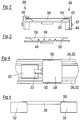
- Fig. 2 shows a support 36 of a transport mover 32 (not shown), which carries a receptacle designed as a tray 38 for an object (not shown).
- the support 36 has two clamping devices 39 which are designed to fix the tray 38 on the support 36.
- a clamping device 39 has a clamping member 40 which is adjustable in the vertical direction between a fixing position (shown on the right in the picture) and a release position (shown on the left in the picture). The clamping member 40 clamps the tray 38 over an edge 50 of the tray 38 against the support 36, a clamping force being applied in the vertical direction.
- the clamping device 39 also includes an actuating nose 42 which is firmly connected to the clamping member 40.
- the clamping element 40 can be adjusted via the actuating nose 42 by an actuating device arranged on the rail side, for example a run-on slope.
- the clamping device 39 further comprises a bistable locking device 44, by means of which the clamping member 40 can be fixed in two different positions, namely the fixing position and the release position, with respect to the support 36.
- a support 36 which has a non-planar topography in the form of elevations 46.
- a tray 38 with depressions 48 arranged.
- the elevations 46 of the support grip into the suitably shaped depressions 48 of the tray 38 in order to secure the tray 38 on the support 36 against a movement in the horizontal direction.
- a tray 38 is shown in a top view, which rests with its edges 50 on two rails of a guide 52 which also forms a support for the tray 38 at the same time.
- the guide 52 guides the tray 38 as it moves in a direction that is horizontal in the image, that is, along the guide rails.
- the tray 38 is secured by the guide 52 against leaving the path of movement, that is to say against a movement in the vertical direction in the image.
- a transport mover 32 is shown between the rails of the guide 52.
- the transport mover 32 is movable in the horizontal direction in the picture along a movement path.
- the transport mover 32 projects above the tray 38 in height, that is to say in the direction out of the image plane, or it projects above at least one embodiment of the tray in height.
- Fig. 5 shows a tray 38 which is carried by two transport movers 32.
- the transport movers 32 thus jointly form a support for the tray 38.
- the tray 38 rests with its edges 50 on the transport movers 32 or on attachment parts of the transport movers 32 provided for this purpose.
- the tray 38 is arranged and held with a depth between the transport movers 32.
- the tray 38 is thus secured in the horizontal and vertical directions relative to the transport movers 32, which move synchronously and at a substantially constant distance during the transport of the tray 38.
- the transport movers 32 are controlled by a control device (not shown) for movement in the horizontal direction in the image, which ensures that the distance between the transport movers 32 remains essentially the same for holding the tray 38. To release or dispense the tray 38, the distance is increased.
- the tray 38 can continue to rest with its edges 50 on the transport movers 32, but in the vertical direction (i.e. upwards) or in the direction perpendicular to the image plane (i.e. transversely to the trajectory) are delivered by the transport movers 32.
- the tray 38 can slide out between the transport movers 32 in a curve in the direction perpendicular to the plane of the image or be pushed out laterally at any point in the track system 34 by means of an ejector device.
- the distance can also be increased by a large amount so that the tray 38 can fall down or can also be lifted up in order to be delivered by the transport movers 32.
- Fig. 6 shows a transport mover 32 guided in a rail system 34, the support 36 of which can be tilted to the left and right about a tilt bearing 54.
- the axis of inclination of the inclination bearing 54 runs parallel to the movement path of the transport mover 32, i.e. perpendicular to the image plane in the illustration, and through the center of the inclination bearing 54.
- the support 36 can therefore be inclined, for example, to compensate for a centrifugal force that occurs when the transport mover 32 turns a curve an object (not shown) carried by the support 36 acts.
- the inclination of the support 36 can be brought about, for example, by drive means of the transport mover 32 arranged in the inclination bearing 54 or by a pendulum mass firmly connected to the support 36.
- the pendulum mass and the overall center of gravity of the inclinable device part are preferably below the inclination axis, so that when the transport mover 32 is cornering, the support 36 is inclined in the direction of the interior of the curve.
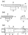
- FIG. 7 two transport movers 32 are shown in a sectional side view, which are arranged horizontally movably in the picture in a track system 34, not shown.
- the transport mover 32 shown on the left has a support 36 for carrying a tray 38.
- the tray 38 is secured against horizontal displacement relative to the transport movers 32 by delimitations 56.
- One of the boundaries 56 namely the one shown on the right, is formed on the transport mover 32 shown on the right.
- the transport movers 32 are in a fixed position relative to one another and are kept at essentially the same distance from one another by a control device (not shown) during transport of the tray 38.
- the transport movers 32 thus jointly fix the tray 38 during transport.
- Fig. 8 are the transport movers 32 of the Fig. 7 shown in a release position.
- the transport mover 32 shown on the right was moved to the right relative to the transport mover 32 shown on the left and the distance between the two transport movers 32 was increased.
- the boundary 56 of the transport mover 32 shown on the right does not secure the tray 38 in this position.
- the tray 38 can therefore be delivered by the transport mover 32 shown on the left in the delivery direction A, that is to say in the horizontal direction to the right.
- the delivery direction A here runs parallel to the transport direction B of the transport movers 32.
- Fig. 9 shows an alternative embodiment of two transport movers 32, which are designed to move a tray 38 together.
- the transport movers 32 move in a rail system 34 along a transport direction B and are in FIG Fig. 9 shown in a release position.
- the transport mover 32 indicated by dashed lines on the left (because it is covered), carries a tray 38 with an edge 50 and has an L-shaped delimitation 56 for the tray 38.
- the tray 38 can be delivered in the delivery direction A, that is to say transversely to the transport direction B, for example by means of a centrifugal force when the transport mover 32 shown on the left is cornering.
- the transport mover 32 shown on the right also has a delimitation 56 which, in a fixed position (not shown), together with the delimitation 56 of the transport mover 32 shown on the left, the tray 38 against a movement transverse to the transport axis B relative to the track system 34 and against a movement parallel to the transport direction B relative to the transport movers 32 secures.
- FIG. 11 shows an alternative embodiment of two transport movers 32 which are designed to carry and secure a tray 38.
- the transport movers 32 are movably driven and guided in a rail system 34 and are in Fig. 10 shown in a fixing position.
- the transport mover 32 shown on the left has a support 36 for the tray 38 and a delimitation 56.
- the transport mover 32 shown on the right also has a delimitation 56.
- Two different formats of trays 38, which rest on the support 36 and are secured by the boundaries 56, are indicated by dash-dot lines.
- the boundaries 56 have a rectangular basic shape with beveled corner areas, so that trays 38 of different sizes or of different shapes can be reliably secured on the support 36.
- a format changeover can be carried out very easily in that, among other things, the distances between the transport movers 32 in the rail system 34 are adjusted accordingly by means of the control device.
- Fig. 11 are the transport movers 32 of the Fig. 10 shown in a release position.
- the transport movers 32 thus have in relation to the fixing position of the Fig. 10 a greater distance to each other.
- a tray 38 is therefore no longer secured by the boundaries 56 on the support 36.
- the tray 38 can thus be delivered in a delivery direction A transverse to the transport direction B of the transport movers 32.
- FIG. 12 The embodiment of the Figures 10 and 11 is in Fig. 12 shown in a side view.
- the two transport movers 32 can be moved horizontally along the track system 34 and are shown in the release position.
- the tray 38 rests on the support 36 of the transport mover 32 shown on the left.
- the boundaries 56 of the transport movers 32 do not secure the tray 38 in this release position, so that the tray 38 can be released in a direction perpendicular to the image plane.
- Fig. 13 shows a plan view of an embodiment of a two-part support 36, one part of which is carried by a respective transport mover 32 hidden in the image.
- the support 36 is delimited by delimitations 56 for a tray 38 (not shown) which are arranged at the front and rear with respect to the direction of movement.
- the two parts of the support 36 are movable relative to one another with their respective transport movers 32 and form complementary contact lines on their side facing the respective other part.
- These complementary contact lines or the parts of the support 36 are formed at an angle in such a way that a, for example, rectangular tray 38 is supported on the support 36, although the parts of the support 36 are at a distance from one another. A falling of the tray 38 can thus be reliably prevented even when the transport movers 32 are in a release position.
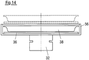
- a transport mover 32 with a support 36 for a tray 38 is shown in a sectional view, which moves in a transport direction B perpendicular to the image plane along a path system 34, not shown.
- the support 36 and the tray 38 are surrounded by a delimitation 56 so that the tray 38 is secured against movement in the horizontal direction.
- the support 36 can be raised into a release position indicated by dashed lines and can be lowered out of this.
- the tray 38 can thus be lifted out of the effective area of the delimitation 56 by lifting the support 36 in order to be in the release position to be delivered.
- the delimitation 56 forms a temporary frame for the tray 38 which disappears when the support 36 is raised.
- Fig. 15 shows a transport mover 32 which is also movable perpendicular to the plane of the drawing and which carries a tray 38 on a support 36 in a sectional view.
- the support 36 has spring clips 58 which can be bent downwards by a rail-side actuating device 60, such as a run-up slope or ramp, as indicated by dashed lines on the right-hand side in the figure.
- the spring clips 58 limit the tray 38 against movement in the horizontal direction transverse to the transport direction B of the transport mover 32.
- the tray 38 In the release position indicated by dashed lines, the tray 38 is not secured against such movement and can be transverse to the transport direction B. be handed in.
- the tray 38 is secured against a movement along the transport direction B relative to the transport mover 32 by a delimitation 56.
- Fig. 16 shows the transport mover 32 of FIG Fig. 15 in a top view.
- the elements of the transport mover 32 covered by the tray 38 are indicated by dashed lines.
- the transport mover 32 forms a support 36, the spring clips 38 forming part of the support 36, while the remaining part of the support 36 is designed to be rigid.
- the tray 38 is fixed against a movement in the vertical direction in the image by means of boundaries 56. After the spring clip 58 has been deformed into a release position, the tray 38 can be delivered in the delivery direction A transversely to the transport direction B, that is, in the horizontal direction in the image.
- the spring clips 58 can be arranged in the transverse direction and / or in the longitudinal direction, as shown, wherein one or more spring clips 58 can be arranged on each side.
- the spring clips 58 of the transport mover 32 can also serve alone as a support 36 and / or as a carrier for the tray 38 and can be bent downward by an external, that is to say on the rail side, force influence, see above that the tray 38 can be pushed off the support 36. It is understood that in the embodiment of Figures 15 and 16 the spring clips 58 shown on the left can also be bent so that the tray 38 can be released or pushed off to the left.
- a transport mover 32 is shown with a support 36 for a tray 38, which is surrounded by a boundary 56 and is therefore indicated by dashed lines.
- the delimitation 56 is rotatable about an axis of rotation D, which runs perpendicular to the image plane and parallel to the transport direction B.
- the limitation 56 is shown in its starting position, that is, a fixing position.
- Fig. 18 is the boundary 56 of the transport mover 32 of the embodiment of FIG Fig. 17 rotated, so in a release position, shown.
- the delimitation 56 was rotated about the axis of rotation D, for example by actuating means arranged on the path system 34, not shown.
- the delimitation 56 no longer limits the tray 38 with respect to a movement transverse to the transport direction B, that is to say in the horizontal direction in the image.
- the tray 38 can thus be dispensed in a dispensing direction A to the left or right of the support 36.
- the tray 38 rests on the support 36 as a rigid plate fixed on the transport mover 32.
- the boundary 56 can also be formed as an enclosure, frame, grid, rods and the like and is rotatably mounted at two opposite points on the support 36 or on the carrier of the transport mover 32.
- the tray 38 can in the fixing position of the Fig. 17 placed from above and / or included in the limitation 56 and in the release position of Fig. 18 pushed off to one side or taken up from one side.
- the delimitation 56 can, for example, be held in the fixing position by a spring force or can be fixed in the fixing position by a latching means (releasable from the outside).
- the actuating means on the railroad side can, for example, cause the delimitation 56 to rotate or pivot mechanically, pneumatically and / or magnetically.
- a support 36 for carrying a tray 38 is shown, which is designed to be deformable.
- the tray 38 deforms the support 36 by its own weight in such a way that one or more displacement sections 64 are formed around the tray 38.
- the displacement sections 64 secure the tray 38 against movement in the horizontal direction.
- the tray 38 thus forms its own bed in the support 36, which bed is adapted to the shape of the tray 38.
- the molding process can be reinforced or supported, for example, by additionally pressing the tray 38 into the support 36.
- the displacement sections 34 form a delimitation in order to accommodate the tray 38.
- Fig. 20 is the edition 36 of the Fig. 19 shown after it has been subjected to a force from two sides by jaws 66 of an actuating device in order to be placed in a release position.
- the tray 38 was lifted out of its bed, the bed, the displacement sections 64 and the boundary for the tray 38 having disappeared.
- the support 36 was deformed by the jaws 66 in such a way that the surface of the support 36 facing the tray 38 bulges upward, the displacement sections 64 forming a boundary, which the tray 38 in Fig. 19 secure horizontally, have disappeared.
- the support 36 can also be stronger than in Fig. 20 A force or pressure can be applied to the tray 38, so that the surface of the support 36 facing the tray 38 curves further, in particular convexly, upwards in order to further simplify the discharge of the tray 38 from the support 36.
- a track 78 of the track system two associated transport movers 32 are shown, each of which has a laterally protruding support area 72 for trays 38 to be transported (indicated by way of example by a dot-dash circle).
- the supports of these two movers 32 that provide these support areas 72 are each shown in FIG Essentially L-shaped and mirror-inverted to one another. In this way, in the area of the track system 78 comprising the guides 76, there is a free space between the movers 32 even when the two supports with their protruding support areas 72 correspond to the situation in FIG Fig. 21 provide a coherent total support surface for the trays 38, or if necessary interrupted by a small gap.
- FIG. 22 Shown embodiment corresponds to that of Fig. 21 , whereby each mover 32 is additionally provided with a delivery aid 74 designed as a scraper or clearer.
- the wipers 74 are each fastened to the one mover 32 and extend towards the support area 72 of the other mover 32, so that when the two movers 32 move apart with the trays 38, they are in a desired manner depending on the configuration of the wipers 74, among other things Cooperate in a way.
- the scrapers 74 can each be rigid and their outreach can be at least substantially adapted to the relative travel path of the two movers 32. Alternatively or additionally, the wiper 74 extending towards a support area 72 can move with this support area 72 when the two movers 32 are moved away from one another.
- the strippers 74 can be elastically deflectable in order to be able to yield when the movers 32 move apart, for example when they come into contact with the trays 38 and the trays 38 are then still partially resting on the support area (s) 72.
- the design and arrangement of the scrapers 74 also depends on the nature of the respective trays 38. It is also possible to comb the support areas 72 by means of the scrapers 74. The scrapers 74 can in principle interact with the trays 38 in any height position.
- blade-like or wire-like scrapers 74 which are moved through between the underside of the trays 38 and the upper side of the support areas 72 when the movers 32 are moved apart in order to close the trays 38 from the support areas 72 if necessary separate or detach, so that the support areas 72 can be better moved away from under the trays 38.
- a fixing device which is stationary in the direction of movement of the movers 32 can be provided, e.g. has a frame-like structure and in the area of the respective delivery position of the trays 38 can be lowered onto a tray resting on the common support area of the two movers 32 and engages around or over this tray.
- a fixing frame can be placed around the tray.
- the moving apart of the movers 32 preferably takes place simultaneously in so far as the two movers 32 are each moved at the same speed and over the same distance in opposite directions. -.-.-.
Landscapes
- Engineering & Computer Science (AREA)
- Mechanical Engineering (AREA)
- Life Sciences & Earth Sciences (AREA)
- Forests & Forestry (AREA)
- Wood Science & Technology (AREA)
- Zoology (AREA)
- Food Science & Technology (AREA)
- Microelectronics & Electronic Packaging (AREA)
- Specific Conveyance Elements (AREA)
- Feeding Of Articles By Means Other Than Belts Or Rollers (AREA)
- Pile Receivers (AREA)
Claims (14)
- Dispositif servant à déplacer des objets, en particulier des portions, comprenant chacun(e) au moins une tranche coupée d'un produit alimentaire, comportant
une pluralité d'organes de transport (32) mobiles individuellement pour au moins un objet respectif,
un système de voie (34) pour les organes de transport (32), dans lequel les organes de transport (32) sont mobiles dans une direction de transport (R) le long d'au moins une voie donnée, et
un moyen de commande pour commander les mouvements des organes de transport (32) dans le système de voie (34),
dans lequel
au moins un organe de transport (32) présente au moins un support (36), dépourvu de cadre à tout moment ou au moins temporairement, pour au moins une partie d'un logement (38), en particulier en forme de bol, destiné à recevoir au moins un objet à déplacer, en particulier pour un emballage ou une partie d'un emballage, de préférence pour un plateau destiné à recevoir au moins une portion, et
les organes de transport (32) comprennent chacun au moins un curseur coopérant avec le système de voie (34), au moins un et en particulier chaque organe de transport (32) comprenant au moins un support fixé au curseur, qui constitue le support dépourvu de cadre (36) ou est relié au support dépourvu de cadre (36), et
en supplément au support (36), il est prévu des moyens de fixation qui sont conçus pour fixer temporairement le logement (38) sur le support (36), caractérisé en ce que
le support (36) est au moins temporairement en position de porte-à-faux dans laquelle le support (36) est latéralement en porte-à-faux au moins avec une zone de support (72) pour le logement, et en ce que il est prévu au moins une paire d'organes de transport (32) qui coopèrent et qui, conjointement avec leurs zones de support (72), forment une zone de support commune, latéralement en porte-à-faux, pour le logement (38), la zone de support (72) étant disposée latéralement en décalage par rapport à un stator du système de voie (34), à un curseur de l'organe de transport (32) et/ou à un guidage pour le curseur, les deux organes de transport (32) étant mobiles l'un par rapport à l'autre pour remettre des logements (38) de telle sorte que les zones de support (72) au-dessous des logements (38) sont mobiles en éloignement. - Dispositif selon la revendication 1,
caractérisé en ce que
les moyens de fixation sont réalisés pour générer une force de maintien qui agit sensiblement dans une direction horizontale et/ou dans un plan parallèle à la direction de transport. - Dispositif selon la revendication 1,
caractérisé en ce que
les moyens de fixation sont réalisés pour fixer le logement (38) par coopération de friction, les moyens de fixation étant en particulier prévus sous la forme d'une surface (37) du support dépourvu de cadre (36), laquelle renforce la friction. - Dispositif selon la revendication 1,
caractérisé en ce que
les moyens de fixation sont réalisés pour fixer le logement (38) par adhérence, les moyens de fixation étant en particulier prévus sous la forme d'une couche adhésive ou d'une couche de colle ou sous la forme d'un ou de plusieurs points individuels d'adhérence ou de colle sur le support dépourvu de cadre (36). - Dispositif selon la revendication 1,
caractérisé en ce que
les moyens de fixation sont réalisés pour fixer le logement (38) par dépression, les moyens de fixation comprenant en particulier au moins un, de préférence une pluralité de moyens d'aspiration disposés de manière répartie. - Dispositif selon la revendication 1,
caractérisé en ce que
les moyens de fixation peuvent être déplacés entre une position de fixation et une position de libération pour le logement (38), en particulier à l'aide d'un moyen d'actionnement (60) prévu au moins partiellement à l'extérieur de l'organe de transport (32) concerné, de préférence sur le système de voie (34), en particulier
les moyens de fixation peuvent être déplacés en passant par un emplacement d'actionnement prévu en particulier sur la voie. - Dispositif selon la revendication 1,
caractérisé en ce que
des moyens de fixation déplaçables entre une position de fixation et une position de libération, comprenant en particulier une ou plusieurs étriers élastiques (58) qui peuvent être fléchis vers la position de libération à l'aide d'une pente ou d'une rampe côté voie, forment au moins une partie du support (36). - Dispositif selon la revendication 1,
caractérisé en ce que
les moyens de fixation comprennent un moyen de serrage (39) réalisé pour fixer le logement (38) à un ou à plusieurs emplacements de serrage. - Dispositif selon la revendication 8,
caractérisé en ce que
le moyen de serrage (39) est réalisé pour serrer le logement (38) entre au moins un élément de serrage (40), en particulier déplaçable, et le support dépourvu de cadre (36). - Dispositif selon la revendication 1,
caractérisé en ce que
le support (36) est pourvu d'une topographie non plane à titre de moyen de fixation, en particulier avec une ou plusieurs cavités (48) et/ou une ou plusieurs élévations (46), et/ou
les moyens de fixation comprennent une ou plusieurs élévations (46) qui, dans une position de fixation, dépassent au-delà d'une surface de support du support (36), la ou chaque élévation (46) étant en particulier déplaçable entre une position de fixation et une position de libération pour le logement (38) et étant de préférence rétractable dans ou sous la surface de support. - Dispositif selon la revendication 1,
caractérisé en ce que
pour au moins une partie d'une surface de support du support (36), les moyens de fixation comprennent une délimitation (56) ou une enceinte en une ou en plusieurs parties qui est déplaçable par rapport à la surface de support, en particulier dans une direction au moins sensiblement verticale, la surface de support pouvant de préférence être relevée pour libérer le logement (38) et être abaissée pour fixer le logement (38). - Dispositif selon la revendication 1,
caractérisé en ce que
l'une au moins des zones de support (72) des deux organes de transport (32) est mobile par rapport à un accessoire de remise (74) qui coopère avec le support (36) pendant la remise, l'accessoire de remise (74) étant réalisé en particulier sous forme de racleur ou de fixateur. - Système comportant un dispositif selon l'une au moins des revendications précédentes et au moins un logement (38), en particulier en forme de bol, pour recevoir au moins un objet à déplacer à l'aide du dispositif,
dans lequel
le logement (38), en particulier son côté inférieur, et le support (36) comprennent des moyens de fixation qui coopèrent et qui sont réalisés de telle sorte que le logement (38) est fixé au moins temporairement sur le support (36) par la coopération des moyens de fixation, les moyens de fixation étant réalisés en particulier sous forme de moyens de coopération de forme. - Système selon la revendication 13,
caractérisé en ce que
le logement (38) est réalisé pour entourer et/ou engager par l'arrière au moins localement le support (36) et/ou pour s'engager au-dessous d'une surface de support du support (36) en contournant latéralement ledit support (36).
Applications Claiming Priority (2)
| Application Number | Priority Date | Filing Date | Title |
|---|---|---|---|
| DE102014119351.2A DE102014119351A1 (de) | 2014-12-22 | 2014-12-22 | Vorrichtung zum bewegen von objekten |
| PCT/EP2015/080706 WO2016102417A1 (fr) | 2014-12-22 | 2015-12-21 | Dispositif pour déplacer des objets |
Publications (2)
| Publication Number | Publication Date |
|---|---|
| EP3233639A1 EP3233639A1 (fr) | 2017-10-25 |
| EP3233639B1 true EP3233639B1 (fr) | 2020-09-16 |
Family
ID=54884068
Family Applications (1)
| Application Number | Title | Priority Date | Filing Date |
|---|---|---|---|
| EP15813076.5A Active EP3233639B1 (fr) | 2014-12-22 | 2015-12-21 | Dispositif pour déplacer des objets |
Country Status (4)
| Country | Link |
|---|---|
| US (1) | US10577136B2 (fr) |
| EP (1) | EP3233639B1 (fr) |
| DE (1) | DE102014119351A1 (fr) |
| WO (1) | WO2016102417A1 (fr) |
Families Citing this family (31)
| Publication number | Priority date | Publication date | Assignee | Title |
|---|---|---|---|---|
| DE102014119351A1 (de) | 2014-12-22 | 2016-06-23 | Weber Maschinenbau Gmbh Breidenbach | Vorrichtung zum bewegen von objekten |
| DE102014119352A1 (de) * | 2014-12-22 | 2016-06-23 | Weber Maschinenbau Gmbh Breidenbach | Bewegungsvorrichtung mit betriebs- und wartungskonfiguration |
| DE102016106621A1 (de) * | 2016-04-11 | 2017-10-12 | Weber Maschinenbau Gmbh Breidenbach | Vorrichtung, Transportmover und Transportmoversystem |
| DE102016109435A1 (de) * | 2016-05-23 | 2017-11-23 | Weber Maschinenbau Gmbh Breidenbach | Transportmover und Vorrichtung mit Transportmover |
| DE102016111357A1 (de) * | 2016-06-10 | 2017-12-14 | Weber Maschinenbau Gmbh Breidenbach | Vorrichtung zum Transport von Objekten |
| ES2802999T3 (es) | 2016-10-28 | 2021-01-22 | Multivac Haggenmueller Kg | Máquina de envasado por embutición profunda |
| EP3315420B1 (fr) | 2016-10-28 | 2020-04-15 | MULTIVAC Sepp Haggenmüller SE & Co. KG | Machine d'emballage par emboutissage |
| DE102017102914A1 (de) | 2017-02-14 | 2018-08-16 | Sig Technology Ag | Verpackungsmaschine sowie Verfahren zum Betreiben einer Verpackungsmaschine |
| DE102017208856A1 (de) | 2017-05-24 | 2018-11-29 | Krones Aktiengesellschaft | Transportvorrichtung und Verfahren zum Transport von Umverpackungen |
| CN108820310B (zh) * | 2018-09-03 | 2020-05-12 | 安徽乐锦记食品有限公司 | 一种青团加工专用包装机 |
| EP3656707B1 (fr) * | 2018-11-23 | 2023-03-15 | Tetra Laval Holdings & Finance S.A. | Gestion de récipients dans un système pour la production de produits alimentaires conditionnés |
| CN109794418B (zh) * | 2019-02-28 | 2024-09-20 | 广东力生智能有限公司 | 翻盘式分拣机 |
| US12036102B2 (en) | 2019-09-17 | 2024-07-16 | Fameccanica.Data S.P.A. | Packaging plant for groups of hygienic absorbent articles, transport apparatus and related methods |
| IT201900016412A1 (it) * | 2019-09-17 | 2021-03-17 | Fameccanica Data Spa | Impianto di confezionamento di gruppi di articoli igienico assorbenti e procedimento |
| US12448224B2 (en) | 2020-12-11 | 2025-10-21 | Laitram, L.L.C. | Conveyor transfer system |
| DE102021105098A1 (de) | 2021-03-03 | 2022-09-08 | Provisur Technologies, Inc. | Nahrungsmittelverarbeitungsanlage |
| DE102021105093A1 (de) * | 2021-03-03 | 2022-09-08 | Provisur Technologies, Inc. | Nahrungsmittelverarbeitungseinrichtung und zugehöriges Betriebsverfahren |
| DE102021105104A1 (de) | 2021-03-03 | 2022-09-08 | Provisur Technologies, Inc. | Bandförderer zum Fördern von Nahrungsmittelprodukten |
| DE102021202068A1 (de) * | 2021-03-03 | 2022-09-08 | Krones Aktiengesellschaft | Verfahren und Verpackungssystem zum Verpacken von Artikeln |
| DE102021119720A1 (de) * | 2021-07-29 | 2023-02-02 | Tvi Entwicklung Und Produktion Gmbh | Verfahren zum Lage-genauen Ablegen einer Portion oder deren Teilen sowie hierfür geeignete Ablage-Vorrichtung |
| CN113787004B (zh) * | 2021-09-17 | 2023-06-20 | 湘潭大学 | 一种垂直升降式物流分拣装置 |
| US20250019181A1 (en) * | 2021-11-16 | 2025-01-16 | Loesch Verpackungstechnik Gmbh + Co. Kg | Method and Device for Conveying and Changing an Orientation of a Piece Product |
| DE102022106160A1 (de) * | 2022-03-16 | 2023-09-21 | Krones Aktiengesellschaft | Identifikation von Bewegungsvorrichtungen eines Linearelektroantrieb-Förderers |
| DE102022106818B3 (de) * | 2022-03-23 | 2023-03-30 | Syntegon Technology Gmbh | Transportsystem und Verfahren zum Transport einer Mehrzahl von Behältnissen |
| US12358736B2 (en) * | 2022-03-31 | 2025-07-15 | Ct Pack S.R.L. | Apparatus and method for conveying articles and plant and method for packaging said articles |
| DE102022113005A1 (de) * | 2022-05-24 | 2023-11-30 | Syntegon Technology Gmbh | Transportsystem für Sterilgut-Tubs und Verwendung eines Transportsystems |
| DE102023108172A1 (de) * | 2023-03-30 | 2024-10-02 | Multivac Sepp Haggenmüller Se & Co. Kg | Tragplattenlinienverteiler zum Verteilen von Fördergut von einer Spur auf mehrere Spuren |
| CN117088062B (zh) * | 2023-10-09 | 2024-02-23 | 浙江聚衣堂服饰有限公司 | 一种制衣流水线智能投放转移系统及其方法 |
| WO2025146503A1 (fr) * | 2024-01-05 | 2025-07-10 | Goodbytz Gmbh | Robot de cuisson plan modulaire |
| CN118418191B (zh) * | 2024-07-03 | 2024-09-13 | 海信集团控股股份有限公司 | 一种机器人放置物品的稳定性评估方法及机器人 |
| CN118458355B (zh) * | 2024-07-12 | 2024-09-24 | 海力特机器人常州有限公司 | 一种用于柔性产线的挂盘矩阵式码垛机 |
Family Cites Families (26)
| Publication number | Priority date | Publication date | Assignee | Title |
|---|---|---|---|---|
| FR2355577A2 (fr) * | 1976-06-22 | 1978-01-20 | Geci | Procede nouveau et installation applicables au tri de paquets |
| CH660471A5 (de) | 1982-05-25 | 1987-04-30 | Feramatic Ag | Transportanlage. |
| DK167274B1 (da) * | 1991-06-18 | 1993-10-04 | Cosan Crisplant As | Fremgangsmaade til destinationssortering og lejlighedsvis mellemlagring af stykgods, f.eks. flybagage, samt sorterings- og lagringsanlaeg til udoevelse af fremgangsmaaden og baerebakke til brug i dette anlaeg |
| FR2679201A1 (fr) * | 1991-07-15 | 1993-01-22 | Legoff Jean Philippe | Procede et dispositif pour la mise en barquette de produits divers. |
| US5388681A (en) * | 1992-10-19 | 1995-02-14 | United Parcel Service Of America, Inc. | Inflatable conveyor belt |
| DE19721850C2 (de) * | 1996-11-05 | 2002-02-28 | Beumer Maschf Bernhard | Kipp-Förderelement für einen Sortierförderer |
| DE19718269A1 (de) * | 1997-04-30 | 1998-11-05 | Beumer Maschf Bernhard | Stückgut-Gliederförderer |
| DE19817255C1 (de) * | 1998-04-19 | 1999-09-09 | Wolf Montage Automationsanlage | Träger zum Transport von Werkstücken |
| DE19853166A1 (de) * | 1998-11-19 | 2000-05-25 | Rovema Gmbh | Vorrichtung und Verfahren zum Einbringen eines Gegenstandes oder mehrerer Gegenstände in eine Verpackung |
| DE10019848A1 (de) * | 2000-04-13 | 2001-10-25 | Mannesmann Ag | Mehrteiliger Behälter für Stückgut |
| US6917136B2 (en) | 2001-10-01 | 2005-07-12 | Magnemotion, Inc. | Synchronous machine design and manufacturing |
| DK1454856T3 (da) | 2003-03-03 | 2006-02-20 | Siemens Ag | Vippeskål-sorteringstransportör |
| DE10320963A1 (de) | 2003-05-09 | 2004-12-16 | Siemens Ag | Fördersystem, inbesondere eine Flughafen-Gepäckförderanlage, und eine Entladeeinrichtung eines Fördersystems für Behälter zum Transportieren von Gütern, insbesondere von Gepäckstücken |
| US7458454B2 (en) | 2004-05-07 | 2008-12-02 | Magnemotion, Inc. | Three-dimensional motion using single-pathway based actuators |
| DE102004030870A1 (de) * | 2004-06-25 | 2006-02-02 | Siemens Ag | Behälter zum Transportieren von Stückgütern |
| DE102004035125A1 (de) | 2004-07-20 | 2006-02-16 | Siemens Ag | Vorrichtung zum Verteilen von Ladungsträgern für Stückgüter |
| DE102007059611B4 (de) * | 2007-12-11 | 2010-09-02 | Gerhard Schubert Gmbh | Verfahren und Vorrichtung zum Transportieren von Objekten |
| DE102008024586A1 (de) * | 2008-05-21 | 2009-11-26 | Beumer Maschinenfabrik Gmbh & Co. Kg | Sortiersystem mit einem Vertikalsorter |
| KR101748447B1 (ko) | 2009-01-23 | 2017-06-16 | 마그네모션, 인코포레이티드 | 쇼트블록 리니어 싱크로너스 모터 및 스위칭 메카니즘에 의해 작동되는 향상된 운송 시스템 |
| DE202010011406U1 (de) * | 2010-08-17 | 2011-11-18 | Weber Maschinenbau Gmbh Breidenbach | Unterlagen zur trennenden Aufnahme von Lebensmittelprodukten |
| DE102011075176A1 (de) * | 2011-05-03 | 2012-11-08 | Robert Bosch Gmbh | Verfahren zum Betreiben eines elektromagnetischen Transfersystems und Transfersystem |
| EP2753158B1 (fr) * | 2011-08-29 | 2020-05-20 | Yokota Technica Limited Company | Transporteur |
| CN103826998B (zh) * | 2011-09-30 | 2017-01-18 | Ats自动化加工系统公司 | 为移动元件提供真空的系统和方法 |
| DE102011119657B4 (de) | 2011-11-29 | 2015-03-12 | Gerhard Schubert Gmbh | Verpackungsmaschine für keimfreies Abpacken |
| US8807320B2 (en) * | 2012-06-21 | 2014-08-19 | Mantissa Corporation | Independent discharge sorting conveyor |
| DE102014119351A1 (de) | 2014-12-22 | 2016-06-23 | Weber Maschinenbau Gmbh Breidenbach | Vorrichtung zum bewegen von objekten |
-
2014
- 2014-12-22 DE DE102014119351.2A patent/DE102014119351A1/de not_active Withdrawn
-
2015
- 2015-12-21 US US15/538,090 patent/US10577136B2/en active Active
- 2015-12-21 WO PCT/EP2015/080706 patent/WO2016102417A1/fr not_active Ceased
- 2015-12-21 EP EP15813076.5A patent/EP3233639B1/fr active Active
Non-Patent Citations (1)
| Title |
|---|
| None * |
Also Published As
| Publication number | Publication date |
|---|---|
| DE102014119351A1 (de) | 2016-06-23 |
| US20180265230A1 (en) | 2018-09-20 |
| US10577136B2 (en) | 2020-03-03 |
| WO2016102417A1 (fr) | 2016-06-30 |
| EP3233639A1 (fr) | 2017-10-25 |
Similar Documents
| Publication | Publication Date | Title |
|---|---|---|
| EP3233639B1 (fr) | Dispositif pour déplacer des objets | |
| EP3271274B1 (fr) | Convoyeur à moteur linéaire à chariots à hauteur variable pour le transport d'objets | |
| EP3227209B1 (fr) | Dispositif de déplacement | |
| DE102014116232B4 (de) | Individueller Transport von Lebensmittelportionen | |
| EP3288731B1 (fr) | Dispositif de découpe | |
| EP3227188B1 (fr) | Dispositif de transport muni d'un système de transfert de portions | |
| EP4714874A2 (fr) | Support de transport électromagnétique autonome de portions de produits alimentaires | |
| DE102006019822B4 (de) | Vorrichtung zum Fördern und Vereinzeln von ferromagnetischen Teilen | |
| DE202018101313U1 (de) | Belade/Entlade-Station für FTF in einem intralogistischen System | |
| EP2311759A2 (fr) | Système de transport pour marchandises et procédé de déchargement de marchandises | |
| WO2012150086A1 (fr) | Dispositif de transfert d'objets | |
| DE102009016334A1 (de) | Greifer zur Anordnung an einem Roboterarm mit einem angetriebenen Niederhalter | |
| EP3040297B1 (fr) | Dispositif destine a deplacer des objets | |
| EP3846630B1 (fr) | Système et procédé pour le transport de volaille | |
| DE102008019110A1 (de) | Blechbeförderungsvorrichtung | |
| EP3445681B1 (fr) | Dispositif servant à déplacer des produits | |
| EP3292058B1 (fr) | Procede et dispositif de tri et/ou de transport de denrées alimentaires | |
| EP3670367B1 (fr) | Installation d'emballage pourvu de pince de préhension | |
| WO2010089150A1 (fr) | Poste de déchargement pour la séparation automatisée d'un emballage et d'un auxiliaire de chargement | |
| DE102020125269A1 (de) | Vorrichtung zum Bewegen von Gegenständen | |
| DE102013208561A1 (de) | Manipulator | |
| DE20307857U1 (de) | Containermanipulator | |
| DE102015212914B4 (de) | Übergabesystem und Übergabeverfahren für Packstücke | |
| DE202014011604U1 (de) | Individueller Transport von Lebensmittelportionen | |
| AT501825A1 (de) | Fördersystem zum fördern und vereinzeln von teilen |
Legal Events
| Date | Code | Title | Description |
|---|---|---|---|
| STAA | Information on the status of an ep patent application or granted ep patent |
Free format text: STATUS: THE INTERNATIONAL PUBLICATION HAS BEEN MADE |
|
| PUAI | Public reference made under article 153(3) epc to a published international application that has entered the european phase |
Free format text: ORIGINAL CODE: 0009012 |
|
| STAA | Information on the status of an ep patent application or granted ep patent |
Free format text: STATUS: REQUEST FOR EXAMINATION WAS MADE |
|
| 17P | Request for examination filed |
Effective date: 20170721 |
|
| AK | Designated contracting states |
Kind code of ref document: A1 Designated state(s): AL AT BE BG CH CY CZ DE DK EE ES FI FR GB GR HR HU IE IS IT LI LT LU LV MC MK MT NL NO PL PT RO RS SE SI SK SM TR |
|
| AX | Request for extension of the european patent |
Extension state: BA ME |
|
| DAV | Request for validation of the european patent (deleted) | ||
| DAX | Request for extension of the european patent (deleted) | ||
| RIN1 | Information on inventor provided before grant (corrected) |
Inventor name: NICHAU, MARCO Inventor name: GERLACH, JOCHEN Inventor name: NISPEL, THOMAS Inventor name: ECKHARDT, CHRISTOPH Inventor name: VON KEUDELL, LEOPOLD Inventor name: ROTHER, INGO Inventor name: ZECHER, STEFFEN Inventor name: LISCHINSKI, GERD Inventor name: BURK, ALEXANDER |
|
| STAA | Information on the status of an ep patent application or granted ep patent |
Free format text: STATUS: EXAMINATION IS IN PROGRESS |
|
| 17Q | First examination report despatched |
Effective date: 20180613 |
|
| GRAP | Despatch of communication of intention to grant a patent |
Free format text: ORIGINAL CODE: EPIDOSNIGR1 |
|
| STAA | Information on the status of an ep patent application or granted ep patent |
Free format text: STATUS: GRANT OF PATENT IS INTENDED |
|
| RIC1 | Information provided on ipc code assigned before grant |
Ipc: B65B 35/44 20060101ALI20200506BHEP Ipc: B65B 25/06 20060101ALI20200506BHEP Ipc: B65B 43/56 20060101ALI20200506BHEP Ipc: B26D 7/32 20060101ALI20200506BHEP Ipc: B65B 59/00 20060101ALI20200506BHEP Ipc: B65B 5/06 20060101AFI20200506BHEP Ipc: B65B 35/24 20060101ALI20200506BHEP Ipc: B65B 5/10 20060101ALI20200506BHEP Ipc: A22C 17/00 20060101ALI20200506BHEP Ipc: B65G 54/02 20060101ALI20200506BHEP Ipc: B65G 47/96 20060101ALI20200506BHEP Ipc: B07C 3/08 20060101ALI20200506BHEP Ipc: B65B 43/52 20060101ALI20200506BHEP Ipc: B65G 35/06 20060101ALI20200506BHEP |
|
| INTG | Intention to grant announced |
Effective date: 20200527 |
|
| GRAS | Grant fee paid |
Free format text: ORIGINAL CODE: EPIDOSNIGR3 |
|
| GRAA | (expected) grant |
Free format text: ORIGINAL CODE: 0009210 |
|
| STAA | Information on the status of an ep patent application or granted ep patent |
Free format text: STATUS: THE PATENT HAS BEEN GRANTED |
|
| AK | Designated contracting states |
Kind code of ref document: B1 Designated state(s): AL AT BE BG CH CY CZ DE DK EE ES FI FR GB GR HR HU IE IS IT LI LT LU LV MC MK MT NL NO PL PT RO RS SE SI SK SM TR |
|
| REG | Reference to a national code |
Ref country code: GB Ref legal event code: FG4D Free format text: NOT ENGLISH |
|
| REG | Reference to a national code |
Ref country code: CH Ref legal event code: EP |
|
| REG | Reference to a national code |
Ref country code: DE Ref legal event code: R096 Ref document number: 502015013484 Country of ref document: DE |
|
| REG | Reference to a national code |
Ref country code: IE Ref legal event code: FG4D Free format text: LANGUAGE OF EP DOCUMENT: GERMAN |
|
| REG | Reference to a national code |
Ref country code: AT Ref legal event code: REF Ref document number: 1313973 Country of ref document: AT Kind code of ref document: T Effective date: 20201015 |
|
| PG25 | Lapsed in a contracting state [announced via postgrant information from national office to epo] |
Ref country code: FI Free format text: LAPSE BECAUSE OF FAILURE TO SUBMIT A TRANSLATION OF THE DESCRIPTION OR TO PAY THE FEE WITHIN THE PRESCRIBED TIME-LIMIT Effective date: 20200916 Ref country code: SE Free format text: LAPSE BECAUSE OF FAILURE TO SUBMIT A TRANSLATION OF THE DESCRIPTION OR TO PAY THE FEE WITHIN THE PRESCRIBED TIME-LIMIT Effective date: 20200916 Ref country code: HR Free format text: LAPSE BECAUSE OF FAILURE TO SUBMIT A TRANSLATION OF THE DESCRIPTION OR TO PAY THE FEE WITHIN THE PRESCRIBED TIME-LIMIT Effective date: 20200916 Ref country code: GR Free format text: LAPSE BECAUSE OF FAILURE TO SUBMIT A TRANSLATION OF THE DESCRIPTION OR TO PAY THE FEE WITHIN THE PRESCRIBED TIME-LIMIT Effective date: 20201217 Ref country code: BG Free format text: LAPSE BECAUSE OF FAILURE TO SUBMIT A TRANSLATION OF THE DESCRIPTION OR TO PAY THE FEE WITHIN THE PRESCRIBED TIME-LIMIT Effective date: 20201216 Ref country code: NO Free format text: LAPSE BECAUSE OF FAILURE TO SUBMIT A TRANSLATION OF THE DESCRIPTION OR TO PAY THE FEE WITHIN THE PRESCRIBED TIME-LIMIT Effective date: 20201216 |
|
| REG | Reference to a national code |
Ref country code: NL Ref legal event code: MP Effective date: 20200916 |
|
| PG25 | Lapsed in a contracting state [announced via postgrant information from national office to epo] |
Ref country code: LV Free format text: LAPSE BECAUSE OF FAILURE TO SUBMIT A TRANSLATION OF THE DESCRIPTION OR TO PAY THE FEE WITHIN THE PRESCRIBED TIME-LIMIT Effective date: 20200916 Ref country code: RS Free format text: LAPSE BECAUSE OF FAILURE TO SUBMIT A TRANSLATION OF THE DESCRIPTION OR TO PAY THE FEE WITHIN THE PRESCRIBED TIME-LIMIT Effective date: 20200916 |
|
| REG | Reference to a national code |
Ref country code: LT Ref legal event code: MG4D |
|
| PG25 | Lapsed in a contracting state [announced via postgrant information from national office to epo] |
Ref country code: RO Free format text: LAPSE BECAUSE OF FAILURE TO SUBMIT A TRANSLATION OF THE DESCRIPTION OR TO PAY THE FEE WITHIN THE PRESCRIBED TIME-LIMIT Effective date: 20200916 Ref country code: SM Free format text: LAPSE BECAUSE OF FAILURE TO SUBMIT A TRANSLATION OF THE DESCRIPTION OR TO PAY THE FEE WITHIN THE PRESCRIBED TIME-LIMIT Effective date: 20200916 Ref country code: PT Free format text: LAPSE BECAUSE OF FAILURE TO SUBMIT A TRANSLATION OF THE DESCRIPTION OR TO PAY THE FEE WITHIN THE PRESCRIBED TIME-LIMIT Effective date: 20210118 Ref country code: EE Free format text: LAPSE BECAUSE OF FAILURE TO SUBMIT A TRANSLATION OF THE DESCRIPTION OR TO PAY THE FEE WITHIN THE PRESCRIBED TIME-LIMIT Effective date: 20200916 Ref country code: LT Free format text: LAPSE BECAUSE OF FAILURE TO SUBMIT A TRANSLATION OF THE DESCRIPTION OR TO PAY THE FEE WITHIN THE PRESCRIBED TIME-LIMIT Effective date: 20200916 Ref country code: CZ Free format text: LAPSE BECAUSE OF FAILURE TO SUBMIT A TRANSLATION OF THE DESCRIPTION OR TO PAY THE FEE WITHIN THE PRESCRIBED TIME-LIMIT Effective date: 20200916 |
|
| PG25 | Lapsed in a contracting state [announced via postgrant information from national office to epo] |
Ref country code: IS Free format text: LAPSE BECAUSE OF FAILURE TO SUBMIT A TRANSLATION OF THE DESCRIPTION OR TO PAY THE FEE WITHIN THE PRESCRIBED TIME-LIMIT Effective date: 20210116 Ref country code: PL Free format text: LAPSE BECAUSE OF FAILURE TO SUBMIT A TRANSLATION OF THE DESCRIPTION OR TO PAY THE FEE WITHIN THE PRESCRIBED TIME-LIMIT Effective date: 20200916 Ref country code: AL Free format text: LAPSE BECAUSE OF FAILURE TO SUBMIT A TRANSLATION OF THE DESCRIPTION OR TO PAY THE FEE WITHIN THE PRESCRIBED TIME-LIMIT Effective date: 20200916 Ref country code: ES Free format text: LAPSE BECAUSE OF FAILURE TO SUBMIT A TRANSLATION OF THE DESCRIPTION OR TO PAY THE FEE WITHIN THE PRESCRIBED TIME-LIMIT Effective date: 20200916 |
|
| REG | Reference to a national code |
Ref country code: DE Ref legal event code: R097 Ref document number: 502015013484 Country of ref document: DE |
|
| PG25 | Lapsed in a contracting state [announced via postgrant information from national office to epo] |
Ref country code: SK Free format text: LAPSE BECAUSE OF FAILURE TO SUBMIT A TRANSLATION OF THE DESCRIPTION OR TO PAY THE FEE WITHIN THE PRESCRIBED TIME-LIMIT Effective date: 20200916 |
|
| PLBE | No opposition filed within time limit |
Free format text: ORIGINAL CODE: 0009261 |
|
| STAA | Information on the status of an ep patent application or granted ep patent |
Free format text: STATUS: NO OPPOSITION FILED WITHIN TIME LIMIT |
|
| REG | Reference to a national code |
Ref country code: CH Ref legal event code: PL |
|
| 26N | No opposition filed |
Effective date: 20210617 |
|
| GBPC | Gb: european patent ceased through non-payment of renewal fee |
Effective date: 20201221 |
|
| PG25 | Lapsed in a contracting state [announced via postgrant information from national office to epo] |
Ref country code: SI Free format text: LAPSE BECAUSE OF FAILURE TO SUBMIT A TRANSLATION OF THE DESCRIPTION OR TO PAY THE FEE WITHIN THE PRESCRIBED TIME-LIMIT Effective date: 20200916 Ref country code: DK Free format text: LAPSE BECAUSE OF FAILURE TO SUBMIT A TRANSLATION OF THE DESCRIPTION OR TO PAY THE FEE WITHIN THE PRESCRIBED TIME-LIMIT Effective date: 20200916 Ref country code: MC Free format text: LAPSE BECAUSE OF FAILURE TO SUBMIT A TRANSLATION OF THE DESCRIPTION OR TO PAY THE FEE WITHIN THE PRESCRIBED TIME-LIMIT Effective date: 20200916 |
|
| REG | Reference to a national code |
Ref country code: BE Ref legal event code: MM Effective date: 20201231 |
|
| PG25 | Lapsed in a contracting state [announced via postgrant information from national office to epo] |
Ref country code: IE Free format text: LAPSE BECAUSE OF NON-PAYMENT OF DUE FEES Effective date: 20201221 Ref country code: IT Free format text: LAPSE BECAUSE OF FAILURE TO SUBMIT A TRANSLATION OF THE DESCRIPTION OR TO PAY THE FEE WITHIN THE PRESCRIBED TIME-LIMIT Effective date: 20200916 Ref country code: LU Free format text: LAPSE BECAUSE OF NON-PAYMENT OF DUE FEES Effective date: 20201221 |
|
| PG25 | Lapsed in a contracting state [announced via postgrant information from national office to epo] |
Ref country code: CH Free format text: LAPSE BECAUSE OF NON-PAYMENT OF DUE FEES Effective date: 20201231 Ref country code: LI Free format text: LAPSE BECAUSE OF NON-PAYMENT OF DUE FEES Effective date: 20201231 Ref country code: GB Free format text: LAPSE BECAUSE OF NON-PAYMENT OF DUE FEES Effective date: 20201221 |
|
| REG | Reference to a national code |
Ref country code: AT Ref legal event code: MM01 Ref document number: 1313973 Country of ref document: AT Kind code of ref document: T Effective date: 20201221 |
|
| PG25 | Lapsed in a contracting state [announced via postgrant information from national office to epo] |
Ref country code: AT Free format text: LAPSE BECAUSE OF NON-PAYMENT OF DUE FEES Effective date: 20201221 |
|
| PG25 | Lapsed in a contracting state [announced via postgrant information from national office to epo] |
Ref country code: IS Free format text: LAPSE BECAUSE OF FAILURE TO SUBMIT A TRANSLATION OF THE DESCRIPTION OR TO PAY THE FEE WITHIN THE PRESCRIBED TIME-LIMIT Effective date: 20210116 Ref country code: TR Free format text: LAPSE BECAUSE OF FAILURE TO SUBMIT A TRANSLATION OF THE DESCRIPTION OR TO PAY THE FEE WITHIN THE PRESCRIBED TIME-LIMIT Effective date: 20200916 Ref country code: MT Free format text: LAPSE BECAUSE OF FAILURE TO SUBMIT A TRANSLATION OF THE DESCRIPTION OR TO PAY THE FEE WITHIN THE PRESCRIBED TIME-LIMIT Effective date: 20200916 Ref country code: CY Free format text: LAPSE BECAUSE OF FAILURE TO SUBMIT A TRANSLATION OF THE DESCRIPTION OR TO PAY THE FEE WITHIN THE PRESCRIBED TIME-LIMIT Effective date: 20200916 |
|
| PG25 | Lapsed in a contracting state [announced via postgrant information from national office to epo] |
Ref country code: MK Free format text: LAPSE BECAUSE OF FAILURE TO SUBMIT A TRANSLATION OF THE DESCRIPTION OR TO PAY THE FEE WITHIN THE PRESCRIBED TIME-LIMIT Effective date: 20200916 |
|
| PG25 | Lapsed in a contracting state [announced via postgrant information from national office to epo] |
Ref country code: BE Free format text: LAPSE BECAUSE OF NON-PAYMENT OF DUE FEES Effective date: 20201231 |
|
| P01 | Opt-out of the competence of the unified patent court (upc) registered |
Effective date: 20230522 |
|
| PG25 | Lapsed in a contracting state [announced via postgrant information from national office to epo] |
Ref country code: NL Free format text: LAPSE BECAUSE OF NON-PAYMENT OF DUE FEES Effective date: 20200923 |
|
| REG | Reference to a national code |
Ref country code: DE Ref legal event code: R081 Ref document number: 502015013484 Country of ref document: DE Owner name: WEBER FOOD TECHNOLOGY SE & CO. KG, DE Free format text: FORMER OWNER: WEBER MASCHINENBAU GMBH BREIDENBACH, 35236 BREIDENBACH, DE Ref country code: DE Ref legal event code: R081 Ref document number: 502015013484 Country of ref document: DE Owner name: WEBER FOOD TECHNOLOGY GMBH, DE Free format text: FORMER OWNER: WEBER MASCHINENBAU GMBH BREIDENBACH, 35236 BREIDENBACH, DE |
|
| PGFP | Annual fee paid to national office [announced via postgrant information from national office to epo] |
Ref country code: FR Payment date: 20241219 Year of fee payment: 10 |
|
| REG | Reference to a national code |
Ref country code: DE Ref legal event code: R081 Ref document number: 502015013484 Country of ref document: DE Owner name: WEBER FOOD TECHNOLOGY SE & CO. KG, DE Free format text: FORMER OWNER: WEBER FOOD TECHNOLOGY GMBH, 35236 BREIDENBACH, DE |
|
| PGFP | Annual fee paid to national office [announced via postgrant information from national office to epo] |
Ref country code: DE Payment date: 20251222 Year of fee payment: 11 |