EP3233696B1 - Procédé de fonctionnement d'un système de sécurité électronique ayant des participants temporaires - Google Patents
Procédé de fonctionnement d'un système de sécurité électronique ayant des participants temporaires Download PDFInfo
- Publication number
- EP3233696B1 EP3233696B1 EP15813766.1A EP15813766A EP3233696B1 EP 3233696 B1 EP3233696 B1 EP 3233696B1 EP 15813766 A EP15813766 A EP 15813766A EP 3233696 B1 EP3233696 B1 EP 3233696B1
- Authority
- EP
- European Patent Office
- Prior art keywords
- control unit
- bus
- subscriber
- temporary subscriber
- temporary
- Prior art date
- Legal status (The legal status is an assumption and is not a legal conclusion. Google has not performed a legal analysis and makes no representation as to the accuracy of the status listed.)
- Active
Links
Images

Classifications
-
- B—PERFORMING OPERATIONS; TRANSPORTING
- B66—HOISTING; LIFTING; HAULING
- B66B—ELEVATORS; ESCALATORS OR MOVING WALKWAYS
- B66B5/00—Applications of checking, fault-correcting, or safety devices in elevators
- B66B5/0006—Monitoring devices or performance analysers
- B66B5/0018—Devices monitoring the operating condition of the elevator system
- B66B5/0031—Devices monitoring the operating condition of the elevator system for safety reasons
-
- B—PERFORMING OPERATIONS; TRANSPORTING
- B66—HOISTING; LIFTING; HAULING
- B66B—ELEVATORS; ESCALATORS OR MOVING WALKWAYS
- B66B1/00—Control systems of elevators in general
- B66B1/34—Details, e.g. call counting devices, data transmission from car to control system, devices giving information to the control system
- B66B1/3407—Setting or modification of parameters of the control system
-
- B—PERFORMING OPERATIONS; TRANSPORTING
- B66—HOISTING; LIFTING; HAULING
- B66B—ELEVATORS; ESCALATORS OR MOVING WALKWAYS
- B66B13/00—Doors, gates, or other apparatus controlling access to, or exit from, cages or lift well landings
- B66B13/22—Operation of door or gate contacts
-
- B—PERFORMING OPERATIONS; TRANSPORTING
- B66—HOISTING; LIFTING; HAULING
- B66B—ELEVATORS; ESCALATORS OR MOVING WALKWAYS
- B66B5/00—Applications of checking, fault-correcting, or safety devices in elevators
- B66B5/0006—Monitoring devices or performance analysers
- B66B5/0018—Devices monitoring the operating condition of the elevator system
- B66B5/0025—Devices monitoring the operating condition of the elevator system for maintenance or repair
Definitions
- the invention relates to a method for operating a security system with temporary subscribers and to a security system which is intended to carry out this method and to an elevator installation with this security system.
- Elevator systems are equipped with safety systems for safe operation.
- These security systems typically consist of serially connected security elements. For example, these security elements can monitor the condition of manhole or car doors.
- Electromechanical safety circuits or bus-based safety circuits are known. The safe operation of such bus-based safety circuits is regularly checked. Construction and test methods of such bus-based safety circuits are, for example EP 1159218 A1 .
- WO 2010/097404 A1 WO 2013/020806 A1 or WO 2014/048826 A1 known.
- a safety system of the elevator installation comprises a control unit, a bus, a plurality of bus nodes which are connected to the control unit via the bus and a plurality of subscribers, which are connected to the control unit via a bus node.
- control unit As a control unit is understood here a unit that has at least a microprocessor, a memory and a memory. Such a control unit is therefore designed to execute computer-aided programs.
- the control unit is configured here as a safety control unit which monitors safety-relevant states of the elevator installation and brings the elevator installation back into a safe state when an unsafe condition occurs. This includes, for example, the monitoring of the shaft door conditions, wherein the elevator system is shut down.
- sensors, switch contacts, operating elements or actuators are understood here, which on the one hand monitor a state of the elevator installation and on the other hand can exert influence on the safe operation of the elevator installation.
- sensors, switch contacts, operating elements or actuators include position, speed or acceleration sensors which monitor a state of motion of an elevator car as well as switch contacts which monitor a shaft or car door state or the passage of a predetermined end position through the elevator car.
- a security system may also include controls via which control commands for the control system of the security system or the elevator installation, the configuration of the security system or the selection of an operating mode can be entered, such as a switch button, an input screen or a manual control device.
- Actuators are understood to be all components that can be actuated by the control unit in order to restore an elevator installation to a safe state after the detection of an impermissible state, such as a drive motor, a holding brake or a safety brake.
- an impermissible state such as a drive motor, a holding brake or a safety brake.
- the security system may have at least one participant who is designed as a temporary participant.
- a temporary subscriber is here understood to be a subscriber who is connected to the security system or the control unit only for a temporary time via a bus node.
- Such temporary subscribers may be designed, for example, as operating elements, governor elements or bridging elements which are or should only be connected to the safety system in a certain operating mode, such as, for example, a normal operating mode, a maintenance mode or a configuration mode.
- the security system is enabled by the control unit for operation when one of the first temporary subscriber or the second temporary subscriber is connected to a bus. It must therefore always be connected to one of two predetermined temporary participants to the bus, so that operation of the safety system and, accordingly, the elevator system is possible. This requires a structured approach to the elevator system and promotes safe operation of the elevator system, especially in work activities that take place within the shaft.
- the security system is set in a jamming mode when none of the first temporary subscriber and the second temporary subscriber or the first temporary subscriber and the second temporary subscriber are simultaneously connected to the bus.
- Under interference mode is understood here a mode in which the elevator system can not be operated or only limited.
- the elevator system is shut down in the fault mode, so that a potentially dangerous situation can not even occur.
- a last journey of the elevator car to a next floor could be permitted in order to avoid trapping of passengers in the elevator car.
- the elevator installation can then be put back into service if the situation that led to the fault mode has been reversed again. So if, for example, a temporary participant is removed, after previously both temporary participants were connected to the security system, so that again only one of the two temporary participants is connected to the security system.
- a first operating mode in particular a maintenance mode
- a second operating mode is only enabled by the control unit if the second temporary subscriber, in particular a governor element, is connected to the bus.
- Hand control device is here understood as a device for controlling the elevator installation, which is operated by a service technician during maintenance work.
- This hand control device preferably comprises four controls, namely one button for performing a downward or upward travel, a button for triggering an emergency stop and optionally a switch for the activation or deactivation of the maintenance mode.
- a governor element is here understood to mean an element which is connected to the security system instead of the first temporary participant.
- the governor element has no function, except that it unlocks a certain operating mode.
- the governor element can be designed, for example, as a simple bridge element.
- the maintenance engineer unmistakably indicates that the elevator system is in maintenance mode and ready for maintenance, so that all necessary maintenance in the maintenance mode are monitored by the control unit or that at least a normal operation is not released because the Governor element is not connected to the security system.
- the first temporary subscriber and the second temporary subscriber are each connectable to the security system at an associated bus node.
- the two bus nodes are arranged spatially close to each other.
- a service technician can see at a glance in which operating mode the elevator system is located.
- these bus nodes are arranged at a location of the elevator installation, the Firstly, they are located in a work area for maintenance work and secondly, they are easily visible to a service technician.
- These bus nodes can be arranged, for example, on a cabin roof or in a shaft pit.
- the first or the second temporary subscriber is physically connected to the security system, for example via the associated bus node at a designated slot of the bus, or the temporary subscriber is wirelessly connected to the security system, for example via a WLAN, Bluetooth or another radio link.
- the first or the second temporary subscriber is registered in the security system by connecting the first or the second temporary subscriber A) to the security system at a bus node, B) recognizing the first or the second temporary subscriber by the control unit, and C) the first or second temporary subscriber is integrated into the security system by the control unit.
- a target list of the participants is implemented on the control unit, which includes at least in each case data for an identification number of a subscriber.
- the first or second temporary subscriber is recognized by the control unit when, in a comparison of an identification number of the first or the second temporary subscriber with the identification numbers of the target list, a match is detected by the control unit.
- the identification number represents a number by means of which a subscriber connected to the security system can be recognized; in particular, this number can represent an identification number that is unique for each subscriber or an identification number that declares a type of the subscriber.
- the identification number can be stored on a storage medium of the subscriber.
- the target list defines an expectation of the control unit, which participants should be connected to the security system. Accordingly, there is an entry in the target list for each participant that can be connected to the security system. This entry includes at least one identification number. Thus, if the first or the second temporary subscriber is connected to the security system, the control unit checks whether this subscriber or his identification number is listed on the target list. If this Check runs positive or the identification number is included in the target list, the temporary participant is considered recognized.
- the detected first or second temporary subscriber is integrated by the control unit by setting an entry of the recognized first or second temporary subscriber in the target list by the control unit from an inactive to an active status.
- This can be accompanied by a change of the operating mode.
- an activation status can be stored on the target list for a temporary subscriber, which the subscriber assumes in a certain operating mode.
- the control unit can automatically change already when recognizing the temporary participant in the operating mode, which is stored in the entry of the temporary participant as an active status in the target list.
- a first mode of operation e.g. a maintenance mode
- a second mode of operation e.g. a normal operating mode.
- the first or the second temporary subscriber is logged off in the security system by D) a disconnection of the first or the second temporary subscriber from the security system by means of a tampering with the security system is announced and E) the temporary subscriber is disconnected from the security system.
- control unit By means of the manipulation of the security system, an expectation is created in the control unit, which can be used for monitoring the logout process of a corresponding temporary subscriber.
- This manipulation can be done for example via a switching element of a manual control device or via a touch-sensitive screen of an input device.
- the first or the second temporary subscriber is deregistered from the control unit by setting the entry of the temporary subscriber in the target list by the control unit from an active to an inactive status. This can be accompanied by a change of the operating mode analogous to the registration process.
- an actual list of subscribers is implemented on the control unit, which represents an image of the participants connected to the security system and an operation of the elevator system is only released when by the control unit at a Comparison of the activated in the target list participants with the registered in the actual list participants a match is detected.
- the actual list represents a list of all subscribers connected to the security system at any given time. Preferably, all recognized participants are listed by their identification numbers in the actual list.
- the comparison between the subscribers listed in the actual list with the subscribers deposited in the target list, in particular those who have an active status for a certain operating mode, is preferably carried out on the basis of the identification numbers listed in the two lists. This comparison ensures that all subscribers intended for a particular operating mode are connected to the security system before a corresponding operating mode is released.
- a further aspect of the invention relates to a safety system of an elevator installation for carrying out the method and to an elevator installation with the said safety system.
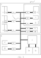
- the in the Fig. 1 schematically illustrated elevator installation 1 comprises a control unit 2, which is connected via a bus 3 to a plurality of bus nodes 41 to 50.
- the control unit 2 can as in Fig. 1 be shown in a separate drive space 8. In a preferred embodiment, the control unit 2 may also be arranged in a shaft 6.
- the reference numeral 6 schematically shows a shaft 6 of a building in which the elevator installation 1 is installed.
- the building has three floors, each floor being equipped with a landing door 61, 62 or 63.
- the respective bus nodes 41, 42 or 43 are each assigned a subscriber, here for example a switching contact 61a, 62a, 63a, which records information relating to the state of the associated landing door 61, 62 or 63 (open, closed, locked) and possibly a fault message for the control unit 2 can generate.
- a subscriber here for example a switching contact 61a, 62a, 63a, which records information relating to the state of the associated landing door 61, 62 or 63 (open, closed, locked) and possibly a fault message for the control unit 2 can generate.
- the elevator installation 1 furthermore has an elevator cage 7.
- the elevator cage 7 is equipped with an elevator door 74, which is likewise assigned to a bus node 44.
- the bus node 44 is a further participant, such as another switch contact 74a assigned, which information regarding the state of the associated elevator door 74 (open, closed, locked) determines and possibly generate a fault message for the control unit 2.
- the elevator installation 1 can furthermore have a bus node 45 and a bus node 46, to which further subscribers are assigned, namely one catching mechanism 75 arranged on the elevator car 7 and one emergency switch 76.
- the catching brake 75 serves for safety braking of the elevator car 7, for example upon reaching one Overspeed of the same.
- the emergency switch 76 By operating the emergency switch 76, the elevator installation 1 can be brought to an immediate standstill in an emergency situation.
- a drive unit is further arranged, which is equipped with two other participants, namely with an emergency brake 87 and a speed sensor 88, which are each assigned to a bus node 47 and 48.
- the drive unit may be arranged in the shaft 6, wherein a separate drive space is eliminated.
- bus nodes 49, 50 are provided, which are arranged in the region of the shaft 6, and are each designed to accommodate a first temporary subscriber and a second temporary subscriber, namely a hand control unit 89a or a governor element 89b.
- the bus nodes 49, 50 may in particular be arranged on the roof of the car 7 or in the pit of the shaft 1, depending on where in the elevator installation 1 maintenance work is to be performed, which require a method of the elevator car 7.
- the two temporary subscribers 89a, 89b are thus connected to the bus 3 or the control unit 2 via the associated bus node 49, 50.
- the two temporary subscribers 89a, 89b can each be connected to a slot of the bus 3 via the corresponding bus node 49, 50 with security system.
- the two temporary subscribers 89a, 89b can also be connected wirelessly to the bus 3, for example via a WLAN, a Bluetooth or a radio connection.
- the hand control unit 89a is designed to control the elevator installation 1 or the elevator car 7 during a maintenance mode and comprises four control elements by way of example, namely one button each for performing an upward or downward travel, a button for triggering an emergency stop and optionally one Switch for activating or deactivating a maintenance mode.
- the governor element 89b is connected to the bus 3 instead of the manual control device 89a and is designed, for example, as a simple bridge element.
- the control unit 2 has a target list 5 a, which defines an expectation of the control unit 2.
- the target list 5a includes, for example, a listing which the participants 61a-63a, 74a, 75, 76, 87, 88, 89a, 89b should be connected to the bus 3 at a certain time.
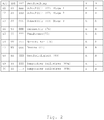
- the control unit 2 has an actual list 5b, which is a listing of all currently connected to the bus 3 participants 61a-63a, 74a, 75, 76, 87, 88, 89a, 89b. Based on Fig. 2 the target list 5a is explained in more detail.
- the target list 5a includes for each contained therein an entry. This entry corresponds to one row of the table.
- a bus address ADD of a bus node 41 to 50 is stored, to which the respective subscriber 61a-63a, 74a, 75, 76, 87, 88, 89a, 89b is connected.
- the control unit 2 can communicate with a bus node 41 to 50 or a subscriber 61a-63a, 74a, 75, 76, 87, 88, 89a, 89b connected thereto. Accordingly, the control unit 2, for example, control signals to a corresponding subscriber, for example to the safety brake 75 via the bus address ADD, 45 address or specifically query states of the switch contact 61a at the bus ADD, 41.
- a first identification number ID1 of a subscriber 61a-63a, 74a, 75, 76, 87, 88, 89a, 89b is stored.
- This first identification number ID1 depends on the type of subscriber.
- subscribers 61a to 63b all logically have the same first identification number ID1 with the value SS, since all three subscribers are designed as type-identical switching contacts 61a to 63a which monitor the status of an associated hoistway door 61 to 63.
- a catch brake 75 has a deviating first identification number ID1 with the value UU.
- the subscribers 61a-63a, 74a, 75, 76, 87, 88, 89a, 89b can also be identifiable via a second identification number ID2.
- This second identification number ID2 represents for each participant 61a-63a, 74a, 75, 76, 87, 88, 89a, 89b z.
- an activation value A or I is stored in the target list 5a for each subscriber 61a-63a, 74a, 75, 76, 87, 88, 89a, 89b, the activation value A being an active status and the activation value I being an inactive status of a subscriber 61a -63a, 74a, 75, 76, 87, 88, 89a, 89b.
- the target list 5a shown has respective activation values A, I for two different operating modes of the elevator installation 1, namely for a normal operating mode N and for a maintenance mode W.
- the manual control unit 89a is thus an active status in maintenance mode W and in normal operation mode inactive status assigned.
- the maintenance mode W is assigned a higher priority than the normal operation mode N.
- the control unit 2 issues a release for operation to the elevator installation 1 if either the first temporary subscriber or the manual control unit 89a or the second temporary subscriber or the governor element 89b is connected to the bus 3 via the associated bus node 49, 50. Accordingly, the control unit 2 interrupts an operation of the elevator installation 1 if neither of the two temporary participants 89a, 89b or both temporary participants 89a, 89b are connected to the bus 3 at the same time.
- the participants 61a to 63a, 74a, 75, 76, 88, 87, 89a, 89b have different activation values A, I stored in the target list 5a. Accordingly, a different expectation is created depending on the operating mode N, W in the control unit 2, which participants must be connected to the bus 3, so that an operating release for the corresponding operating mode N, W takes place.
- the participants permanently connected to the bus 3 participants 61a to 63a, 74a, 75, 76, 88, 87 are of course in both modes of operation W, N activated.
- the temporary participants 89a, 89b are only ever activated for one of the two operating modes N, W, namely the manual control device 89a for the maintenance mode W and the governor element 89b for a normal operating mode N.
- the first temporary subscriber 89a is registered with the control unit 2 by the temporary subscriber 89a in a first step A according to FIG Fig. 3 is connected to the bus node 49 on the bus 3.
- the control unit 2 detects in a second step B due to a stored on the storage medium of the first temporary subscriber 89a identification number ID1, ID2 the newly connected participants 89a.
- the first identification number ID1 indicates the type of the first temporary subscriber 89a, that is to say that this is a hand control unit 89a.
- the second identification number ID2 represents a unique identification number of the temporary participant 89a.
- a plurality of second identification numbers ID2 may also be provided for the entry of the manual control unit 89a or, alternatively, an entry with a separate second identification number ID2 may be stored for different manual control units 89a.
- a first identification number ID1 with the value YY and a second identification number ID2 with the value III are stored by way of example for the manual control unit 89a.
- the control unit 2 reads out the values YY and III stored on the storage medium of the subscriber 89a for the identification numbers ID1 and ID2 and compares them with those in the target list 5a listed values YY and III. If there is a match, the subscriber 89a is considered recognized. In this case, only the first identification number ID 1 can be used for the recognition of the subscriber 89a.
- the manual control unit 89a is now integrated into the system by the control unit 2 in a third step C by setting the status of the manual control unit 89a in the entry in the target list 5a from inactive I to active A. For example, this may be accompanied by an automatic change of the operating mode, namely from a normal operating mode N to a maintenance mode W.
- the control unit 2 can automatically switch to the maintenance mode W after recognition of the manual control device 89a.
- the control unit 2 is also so programmable that the maintenance mode W is released only by pressing the activation switch on the manual control unit 89a. After completion of the activation of the manual control unit 89a this is considered to be integrated in the security system.
- the hand control unit 89a After the hand control unit 89a has been recognized and integrated, the hand control unit 89a can be given the function intended for it, namely the control of the elevator installation 1 during the maintenance mode W.
- the manual control unit 89a is deregistered from the control unit 2, in a further step D according to Fig. 4 a disconnection of the manual control unit 89a, in particular together with bus node 49 from the bus 3 based on a reset of the activation switch of the manual control unit 89a of the control unit 2 is announced.
- the manual control unit 89a in particular together with bus node 49, can finally be disconnected from the bus 3 in a last step E.
- an actual list 5b of the subscribers 61a-63a, 74a, 75, 76, 87, 88, 89a, 89b is implemented on the control unit 2, which is an image of the subscribers 61a-63a connected to the security system 5b at some time, 74a, 75, 76, 87, 88, 89a, 89b.
- the actual list 5b is constructed very much like the target list 5a and substantially comprises the first four columns of the target list 5a.
- the control unit 2 thus reads for each existing bus node 41 to 50 or its address ADD and the identification numbers ID1, ID2, the participants 61a-63a, 74a, 75, 76, 87, 88, 89a, 89b connected to the respective bus node 41 to 50 out.
- the operation of the elevator installation 1 is only enabled by the control unit 2 if the control unit 2, in a comparison of the identification numbers ID1, ID2, in particular the identification numbers ID1, ID2 of the entries of the target list 5a, for the active status in a respective operating mode N, W is deposited with those of the actual list 5b determines a match.
Landscapes
- Engineering & Computer Science (AREA)
- Automation & Control Theory (AREA)
- Computer Networks & Wireless Communication (AREA)
- Maintenance And Inspection Apparatuses For Elevators (AREA)
- Indicating And Signalling Devices For Elevators (AREA)
- Elevator Control (AREA)
Claims (12)
- Procédé pour le fonctionnement d'un système de sécurité d'une installation d'ascenseur (1) comportant- une unité de commande (2),- un bus (3),- une pluralité de noeuds de bus (41 - 50) reliés à l'unité de commande (2) par l'intermédiaire du bus (3), et- une pluralité d'abonnés (61a - 63a, 74a, 75, 76, 87, 88, 89a, 89b) reliés à l'unité de commande (2) par l'intermédiaire d'un noeud de bus (41 - 50), au moins un abonné de la pluralité d'abonnés (61a - 63a, 74a, 75, 76, 87, 88, 89a, 89b) étant interprété comme abonné temporaire (89a, 89b), le procédé étant caractérisé par l'étape de :- validation du système de sécurité par l'unité de commande (2) pour un fonctionnement, si l'un du premier abonné temporaire (89a) ou du second abonné temporaire (89b) est relié au bus (3).
- Procédé selon la revendication 1, dans lequel
le système de sécurité est placé dans un mode défaut si aucun du premier abonné temporaire (89a) et du second abonné temporaire (89b) ou du premier abonné temporaire (89a) et du second abonné temporaire (89b) simultanément n'est relié au bus (3). - Procédé selon l'une des revendications 1 ou 2, dans lequel
un premier mode de fonctionnement, en particulier un mode de maintenance (W) n'est validé par l'unité de commande (2) que si le premier abonné temporaire (89a), en particulier un appareil de commande portatif ou une interface de saisie, est relié au bus (3). - Procédé selon l'une des revendications 1 ou 2, dans lequel
un second mode de fonctionnement, en particulier un mode de fonctionnement normal (N) n'est validé par l'unité de commande (2) que si le second abonné temporaire (89b), en particulier un élément de gouvernance, est relié au bus (3). - Procédé selon la revendication 1, dans lequel
le premier ou le second abonné temporaire (89a, 89b) est loggé dans le système de sécurité du fait que- A) le premier ou le second abonné temporaire (89a, 89b) est relié au système de sécurité au niveau du bus (3),- B) le premier ou le second abonné temporaire (89a, 89b) est reconnu par l'unité de commande, et- C) le premier ou le second abonné temporaire (89a, 89b) est intégré dans le système de sécurité par l'unité de commande (2). - Procédé selon la revendication 5, dans lequel
une liste programmée (5a) des abonnés (61a- 63a, 74a, 75, 76, 87, 88, 89a, 89b) est implémentée sur l'unité de commande (2), laquelle liste contient au moins respectivement des données relatives à un numéro d'identification (ID1, ID2) d'un abonné (61a - 63a, 74a, 75, 76, 87, 88, 89a, 89b), et l'abonné temporaire (89a, 89b) est reconnu par l'unité de commande (2) lorsqu'une correspondance est constatée par l'unité de commande (2) lors d'une comparaison d'un numéro d'identification (ID1, ID2) du premier ou du second abonné temporaire (89a, 89b) avec les numéros d'identification (ID1, ID2) de la liste programmée (5a). - Procédé selon la revendication 6, dans lequel
le premier ou second abonné (89a, 89b) temporaire reconnu est intégré par l'unité de commande (2) du fait qu'une entrée du premier ou du second abonné (89a, 89b) temporaire reconnu passe du statut inactif (I) à un statut actif (A) dans la liste programmée (5a). - Procédé selon la revendication 1, dans lequel
le premier ou le second abonné (89a, 89b) temporaire est déloggé du système de sécurité du fait que- D) une séparation du premier ou du second abonné (89a, 89b) temporaire est annoncée par le système de sécurité au moyen d'une manipulation au niveau du système de sécurité et- E) l'abonné (89a, 89b) temporaire est séparé du système de sécurité. - Procédé selon la revendication 8, dans lequel
une liste programmée (5a) des abonnés (61a - 63a, 74a, 75, 76, 87, 88, 89a, 89b) est implémentée sur l'unité de commande (2), laquelle liste contient au moins respectivement des données relatives à un numéro d'identification (ID1, ID2) d'un abonné (61a - 63a, 74a, 75, 76, 87, 88, 89a, 89b), et le premier ou le second abonné (89a, 89b) temporaire est déloggé par l'unité de commande (2) du fait que l'unité de commande (2) fasse passer une entrée du premier ou du second abonné (89a, 89b) temporaire du statut inactif (I) à un statut actif (A) dans la liste programmée (5a). - Procédé selon l'une des revendications 6 ou 9, dans lequel
une liste effective (5a) des abonnés (61a - 63a, 74a, 75, 76, 87, 88, 89a, 89b) est implémentée sur l'unité de commande (2), laquelle liste représente une image des abonnés (61a - 63a, 74a, 75, 76, 87, 88, 89a, 89b) reliés au système de sécurité et un fonctionnement de l'installation d'ascenseur (1) ne sera validé que si une correspondance est constatée par l'unité de commande (2) lors d'une comparaison des abonnés (61a - 63a, 74a, 75, 76, 87, 88, 89a, 89b) activés dans la liste programmée (5a) avec les abonnés (61a - 63a, 74a, 75, 76, 87, 88, 89a, 89b) inscrits dans la liste effective (5b). - Système de sécurité pour une installation d'ascenseur (1), comportant- une unité de commande (2),- un bus (3),- une pluralité de noeuds de bus (41 - 50) reliés à l'unité de commande (2) par l'intermédiaire du bus (3), et- une pluralité d'abonnés (61a - 63a, 74a, 75, 76, 87, 88, 89a, 89b), parmi lesquels moins un abonné est interprété comme abonné temporaire (89a, 89b), et qui sont reliés à l'unité de commande (2) par l'intermédiaire d'un noeud de bus (41 - 50), caractérisé en ce que le système de sécurité est conçu pour exécuter le procédé selon l'une des revendications 1 à 10.
- Installation d'ascenseur (1) comportant un système de sécurité selon la revendication 11.
Applications Claiming Priority (2)
| Application Number | Priority Date | Filing Date | Title |
|---|---|---|---|
| EP14199056 | 2014-12-18 | ||
| PCT/EP2015/079748 WO2016096826A1 (fr) | 2014-12-18 | 2015-12-15 | Procédé pour faire fonctionner un système de sécurité électronique comprenant des abonnés temporaires |
Publications (2)
| Publication Number | Publication Date |
|---|---|
| EP3233696A1 EP3233696A1 (fr) | 2017-10-25 |
| EP3233696B1 true EP3233696B1 (fr) | 2019-02-20 |
Family
ID=52146222
Family Applications (1)
| Application Number | Title | Priority Date | Filing Date |
|---|---|---|---|
| EP15813766.1A Active EP3233696B1 (fr) | 2014-12-18 | 2015-12-15 | Procédé de fonctionnement d'un système de sécurité électronique ayant des participants temporaires |
Country Status (9)
| Country | Link |
|---|---|
| US (1) | US10214384B2 (fr) |
| EP (1) | EP3233696B1 (fr) |
| CN (1) | CN107250019B (fr) |
| AU (1) | AU2015367705B2 (fr) |
| BR (1) | BR112017011121B1 (fr) |
| CA (1) | CA2969376C (fr) |
| ES (1) | ES2722432T3 (fr) |
| RU (1) | RU2696645C2 (fr) |
| WO (1) | WO2016096826A1 (fr) |
Families Citing this family (4)
| Publication number | Priority date | Publication date | Assignee | Title |
|---|---|---|---|---|
| CA2969378C (fr) * | 2014-12-18 | 2023-07-04 | Inventio Ag | Methode d'exploitation d'un systeme de securite electronique avec des participants temporaires |
| WO2017191186A1 (fr) * | 2016-05-04 | 2017-11-09 | Inventio Ag | Installation de transport de personnes munie d'une unité de commande centrale et de plusieurs appareils de terrain et mettant en œuvre un procédé d'identification des dysfonctionnements |
| WO2019011828A1 (fr) * | 2017-07-14 | 2019-01-17 | Inventio Ag | Procédé de configuration de paramètres de configuration concernant la sécurité dans un système de transport de personnes |
| EP3828117B1 (fr) * | 2019-11-26 | 2024-02-14 | Otis Elevator Company | Déclencheur de frein de sécurité |
Family Cites Families (16)
| Publication number | Priority date | Publication date | Assignee | Title |
|---|---|---|---|---|
| US4650037A (en) * | 1985-06-05 | 1987-03-17 | Westinghouse Electric Corp. | Elevator system |
| JPH01226678A (ja) * | 1988-03-04 | 1989-09-11 | Hitachi Ltd | エレベーター制御装置 |
| JPH01247382A (ja) * | 1988-03-30 | 1989-10-03 | Hitachi Ltd | エレベーター制御システム |
| US5387769A (en) * | 1993-06-01 | 1995-02-07 | Otis Elevator Company | Local area network between an elevator system building controller, group controller and car controller, using redundant communication links |
| US6173814B1 (en) * | 1999-03-04 | 2001-01-16 | Otis Elevator Company | Electronic safety system for elevators having a dual redundant safety bus |
| RU2346877C2 (ru) * | 2003-05-28 | 2009-02-20 | Инвенцио Аг | Способ и устройство для обслуживания лифта или эскалатора |
| PT1510492E (pt) * | 2003-08-25 | 2007-07-11 | Inventio Ag | Método para testar uma instalação de ascensor, bem como instalação de ascensor. |
| KR101023358B1 (ko) * | 2006-10-25 | 2011-03-18 | 미쓰비시덴키 가부시키가이샤 | 엘리베이터 장치 |
| PL2167413T3 (pl) * | 2007-07-17 | 2013-05-31 | Inventio Ag | Sposób nadzorowania dźwigu szybowego |
| WO2010031426A1 (fr) * | 2008-09-16 | 2010-03-25 | Inventio Ag | Procédé destiné à moderniser une installation d'ascenseur |
| SG173848A1 (en) * | 2009-02-25 | 2011-09-29 | Inventio Ag | Elevator having a monitoring system |
| CN103068710B (zh) * | 2010-10-01 | 2015-07-22 | 三菱电机株式会社 | 电梯的运转模式切换系统 |
| HUE025325T2 (en) | 2011-08-11 | 2016-01-28 | Inventio Ag | Test method of an elevator system and a monitoring device for performing the test method |
| ES2607145T3 (es) * | 2012-09-25 | 2017-03-29 | Inventio Ag | Procedimiento para reiniciar un sistema de seguridad de una instalación de ascensor |
| CA2969378C (fr) * | 2014-12-18 | 2023-07-04 | Inventio Ag | Methode d'exploitation d'un systeme de securite electronique avec des participants temporaires |
| BR112017010993A2 (pt) * | 2014-12-18 | 2017-12-26 | Inventio Ag | processo para operar um sistema de segurança eletrônico com assinantes temporários |
-
2015
- 2015-12-15 WO PCT/EP2015/079748 patent/WO2016096826A1/fr not_active Ceased
- 2015-12-15 CA CA2969376A patent/CA2969376C/fr active Active
- 2015-12-15 US US15/535,759 patent/US10214384B2/en active Active
- 2015-12-15 EP EP15813766.1A patent/EP3233696B1/fr active Active
- 2015-12-15 RU RU2017123947A patent/RU2696645C2/ru active
- 2015-12-15 AU AU2015367705A patent/AU2015367705B2/en active Active
- 2015-12-15 BR BR112017011121-7A patent/BR112017011121B1/pt not_active IP Right Cessation
- 2015-12-15 ES ES15813766T patent/ES2722432T3/es active Active
- 2015-12-15 CN CN201580076278.XA patent/CN107250019B/zh active Active
Non-Patent Citations (1)
| Title |
|---|
| None * |
Also Published As
| Publication number | Publication date |
|---|---|
| CA2969376C (fr) | 2023-05-16 |
| US10214384B2 (en) | 2019-02-26 |
| EP3233696A1 (fr) | 2017-10-25 |
| RU2017123947A (ru) | 2019-01-23 |
| ES2722432T3 (es) | 2019-08-12 |
| WO2016096826A1 (fr) | 2016-06-23 |
| RU2017123947A3 (fr) | 2019-05-28 |
| AU2015367705A1 (en) | 2017-07-13 |
| AU2015367705B2 (en) | 2018-12-13 |
| BR112017011121A2 (pt) | 2018-01-23 |
| RU2696645C2 (ru) | 2019-08-05 |
| US20170341905A1 (en) | 2017-11-30 |
| CN107250019A (zh) | 2017-10-13 |
| BR112017011121B1 (pt) | 2022-08-23 |
| CN107250019B (zh) | 2019-12-31 |
| CA2969376A1 (fr) | 2016-06-23 |
Similar Documents
| Publication | Publication Date | Title |
|---|---|---|
| EP3233697B1 (fr) | Procédé de fonctionnement d'un système de sécurité électronique ayant des participants temporaires | |
| EP3061212B1 (fr) | Procédé et dispositif destiné à la mise en service d'une installation d'ascenseur | |
| EP3230192B1 (fr) | Procédé et dispositif destiné à la mise en service d'un ascenseur | |
| EP3233698B1 (fr) | Procédé de fonctionnement d'un système de sécurité électronique ayant des participants temporaires | |
| EP2022742B1 (fr) | Système d'ascenseur | |
| EP3793925B1 (fr) | Système de commande d'inspection d'une installation d'ascenseur ainsi que procédé de commutation d'une installation d'ascenseur entre un fonctionnement normal et un fonctionnement d'inspection | |
| EP3595997B1 (fr) | Procédé et dispositif de surveillance de paramètres de fonctionnement dans une installation de transport de personnes | |
| EP3814267B1 (fr) | Système de commutation de sécurité et procédé de commutation d'une installation d'ascenseur entre un mode de fonctionnement normal et un mode de fonctionnement d'inspection | |
| WO2016096826A1 (fr) | Procédé pour faire fonctionner un système de sécurité électronique comprenant des abonnés temporaires | |
| WO2017191186A1 (fr) | Installation de transport de personnes munie d'une unité de commande centrale et de plusieurs appareils de terrain et mettant en œuvre un procédé d'identification des dysfonctionnements | |
| DE112016006975T5 (de) | Sicherheitssteuerungsvorrichtung und Sicherheitssteuerungsverfahren für einen Mehrfachkabinenaufzug | |
| WO2021197811A1 (fr) | Dispositif de surveillance de sécurité, et procédé de surveillance de sécurité d'un système d'ascenseur | |
| EP4267503A1 (fr) | Ascenseur, procédé de commande d'un ascenseur | |
| EP3060509B1 (fr) | Système de sécurité pour un ascenseur, installation d'ascenseur et procédé de fonctionnement d'un tel système de sécurité | |
| EP1050503B1 (fr) | Système d'aide pour ascenseurs | |
| EP3257798A1 (fr) | Installation de transport de personnes comprenant un premier et au moins un second module d'evaluation | |
| EP3483033A1 (fr) | Procédé et unité de commande embarquée permettant de commander et / ou surveiller les composants d'un véhicule ferroviaire | |
| EP1847499B1 (fr) | Procédé de réglage des agencements à étages d'un grand nombre d'unités de commandes d'une installation d'ascenseur | |
| EP2836453B1 (fr) | Dispositif de surveillance d'une installation d'élévation | |
| WO2019185354A1 (fr) | Dispositif destiné à commander un commutateur semi-conducteur d'un système de sécurité d'un équipement de transport de personnes et commutateur de sécurité doté de ce dispositif | |
| WO2024000004A1 (fr) | Commutation améliorée d'un mode d'économie d'énergie à un mode de fonctionnement normal dans un système de prélèvement | |
| EP4414306A1 (fr) | Dispositif de commande pour une installation de transport de personnes et procédé de fonctionnement d'un dispositif de commande pour une installation de transport de personnes | |
| EP4634101A1 (fr) | Procédé de désactivation du fonctionnement d'un ascenseur et dispositif de commande d'ascenseur | |
| EP3647246A1 (fr) | Commande d'ascenseur modulaire et procédé de commande du fonctionnement des composants actionneurs d'une installation d'ascenseur | |
| WO2017167758A1 (fr) | Système d'ascenseur |
Legal Events
| Date | Code | Title | Description |
|---|---|---|---|
| STAA | Information on the status of an ep patent application or granted ep patent |
Free format text: STATUS: THE INTERNATIONAL PUBLICATION HAS BEEN MADE |
|
| PUAI | Public reference made under article 153(3) epc to a published international application that has entered the european phase |
Free format text: ORIGINAL CODE: 0009012 |
|
| STAA | Information on the status of an ep patent application or granted ep patent |
Free format text: STATUS: REQUEST FOR EXAMINATION WAS MADE |
|
| 17P | Request for examination filed |
Effective date: 20170524 |
|
| AK | Designated contracting states |
Kind code of ref document: A1 Designated state(s): AL AT BE BG CH CY CZ DE DK EE ES FI FR GB GR HR HU IE IS IT LI LT LU LV MC MK MT NL NO PL PT RO RS SE SI SK SM TR |
|
| AX | Request for extension of the european patent |
Extension state: BA ME |
|
| DAV | Request for validation of the european patent (deleted) | ||
| DAX | Request for extension of the european patent (deleted) | ||
| GRAP | Despatch of communication of intention to grant a patent |
Free format text: ORIGINAL CODE: EPIDOSNIGR1 |
|
| STAA | Information on the status of an ep patent application or granted ep patent |
Free format text: STATUS: GRANT OF PATENT IS INTENDED |
|
| INTG | Intention to grant announced |
Effective date: 20180919 |
|
| GRAS | Grant fee paid |
Free format text: ORIGINAL CODE: EPIDOSNIGR3 |
|
| GRAA | (expected) grant |
Free format text: ORIGINAL CODE: 0009210 |
|
| STAA | Information on the status of an ep patent application or granted ep patent |
Free format text: STATUS: THE PATENT HAS BEEN GRANTED |
|
| AK | Designated contracting states |
Kind code of ref document: B1 Designated state(s): AL AT BE BG CH CY CZ DE DK EE ES FI FR GB GR HR HU IE IS IT LI LT LU LV MC MK MT NL NO PL PT RO RS SE SI SK SM TR |
|
| REG | Reference to a national code |
Ref country code: GB Ref legal event code: FG4D Free format text: NOT ENGLISH |
|
| REG | Reference to a national code |
Ref country code: CH Ref legal event code: EP |
|
| REG | Reference to a national code |
Ref country code: DE Ref legal event code: R096 Ref document number: 502015008063 Country of ref document: DE |
|
| REG | Reference to a national code |
Ref country code: AT Ref legal event code: REF Ref document number: 1097887 Country of ref document: AT Kind code of ref document: T Effective date: 20190315 |
|
| REG | Reference to a national code |
Ref country code: IE Ref legal event code: FG4D Free format text: LANGUAGE OF EP DOCUMENT: GERMAN |
|
| REG | Reference to a national code |
Ref country code: NL Ref legal event code: FP |
|
| REG | Reference to a national code |
Ref country code: LT Ref legal event code: MG4D |
|
| PG25 | Lapsed in a contracting state [announced via postgrant information from national office to epo] |
Ref country code: SE Free format text: LAPSE BECAUSE OF FAILURE TO SUBMIT A TRANSLATION OF THE DESCRIPTION OR TO PAY THE FEE WITHIN THE PRESCRIBED TIME-LIMIT Effective date: 20190220 Ref country code: PT Free format text: LAPSE BECAUSE OF FAILURE TO SUBMIT A TRANSLATION OF THE DESCRIPTION OR TO PAY THE FEE WITHIN THE PRESCRIBED TIME-LIMIT Effective date: 20190620 Ref country code: LT Free format text: LAPSE BECAUSE OF FAILURE TO SUBMIT A TRANSLATION OF THE DESCRIPTION OR TO PAY THE FEE WITHIN THE PRESCRIBED TIME-LIMIT Effective date: 20190220 Ref country code: NO Free format text: LAPSE BECAUSE OF FAILURE TO SUBMIT A TRANSLATION OF THE DESCRIPTION OR TO PAY THE FEE WITHIN THE PRESCRIBED TIME-LIMIT Effective date: 20190520 |
|
| REG | Reference to a national code |
Ref country code: ES Ref legal event code: FG2A Ref document number: 2722432 Country of ref document: ES Kind code of ref document: T3 Effective date: 20190812 |
|
| PG25 | Lapsed in a contracting state [announced via postgrant information from national office to epo] |
Ref country code: IS Free format text: LAPSE BECAUSE OF FAILURE TO SUBMIT A TRANSLATION OF THE DESCRIPTION OR TO PAY THE FEE WITHIN THE PRESCRIBED TIME-LIMIT Effective date: 20190620 Ref country code: GR Free format text: LAPSE BECAUSE OF FAILURE TO SUBMIT A TRANSLATION OF THE DESCRIPTION OR TO PAY THE FEE WITHIN THE PRESCRIBED TIME-LIMIT Effective date: 20190521 Ref country code: RS Free format text: LAPSE BECAUSE OF FAILURE TO SUBMIT A TRANSLATION OF THE DESCRIPTION OR TO PAY THE FEE WITHIN THE PRESCRIBED TIME-LIMIT Effective date: 20190220 Ref country code: BG Free format text: LAPSE BECAUSE OF FAILURE TO SUBMIT A TRANSLATION OF THE DESCRIPTION OR TO PAY THE FEE WITHIN THE PRESCRIBED TIME-LIMIT Effective date: 20190520 Ref country code: LV Free format text: LAPSE BECAUSE OF FAILURE TO SUBMIT A TRANSLATION OF THE DESCRIPTION OR TO PAY THE FEE WITHIN THE PRESCRIBED TIME-LIMIT Effective date: 20190220 Ref country code: HR Free format text: LAPSE BECAUSE OF FAILURE TO SUBMIT A TRANSLATION OF THE DESCRIPTION OR TO PAY THE FEE WITHIN THE PRESCRIBED TIME-LIMIT Effective date: 20190220 |
|
| PG25 | Lapsed in a contracting state [announced via postgrant information from national office to epo] |
Ref country code: CZ Free format text: LAPSE BECAUSE OF FAILURE TO SUBMIT A TRANSLATION OF THE DESCRIPTION OR TO PAY THE FEE WITHIN THE PRESCRIBED TIME-LIMIT Effective date: 20190220 Ref country code: RO Free format text: LAPSE BECAUSE OF FAILURE TO SUBMIT A TRANSLATION OF THE DESCRIPTION OR TO PAY THE FEE WITHIN THE PRESCRIBED TIME-LIMIT Effective date: 20190220 Ref country code: AL Free format text: LAPSE BECAUSE OF FAILURE TO SUBMIT A TRANSLATION OF THE DESCRIPTION OR TO PAY THE FEE WITHIN THE PRESCRIBED TIME-LIMIT Effective date: 20190220 Ref country code: SK Free format text: LAPSE BECAUSE OF FAILURE TO SUBMIT A TRANSLATION OF THE DESCRIPTION OR TO PAY THE FEE WITHIN THE PRESCRIBED TIME-LIMIT Effective date: 20190220 Ref country code: DK Free format text: LAPSE BECAUSE OF FAILURE TO SUBMIT A TRANSLATION OF THE DESCRIPTION OR TO PAY THE FEE WITHIN THE PRESCRIBED TIME-LIMIT Effective date: 20190220 Ref country code: IT Free format text: LAPSE BECAUSE OF FAILURE TO SUBMIT A TRANSLATION OF THE DESCRIPTION OR TO PAY THE FEE WITHIN THE PRESCRIBED TIME-LIMIT Effective date: 20190220 Ref country code: EE Free format text: LAPSE BECAUSE OF FAILURE TO SUBMIT A TRANSLATION OF THE DESCRIPTION OR TO PAY THE FEE WITHIN THE PRESCRIBED TIME-LIMIT Effective date: 20190220 |
|
| REG | Reference to a national code |
Ref country code: DE Ref legal event code: R097 Ref document number: 502015008063 Country of ref document: DE |
|
| PG25 | Lapsed in a contracting state [announced via postgrant information from national office to epo] |
Ref country code: SM Free format text: LAPSE BECAUSE OF FAILURE TO SUBMIT A TRANSLATION OF THE DESCRIPTION OR TO PAY THE FEE WITHIN THE PRESCRIBED TIME-LIMIT Effective date: 20190220 Ref country code: PL Free format text: LAPSE BECAUSE OF FAILURE TO SUBMIT A TRANSLATION OF THE DESCRIPTION OR TO PAY THE FEE WITHIN THE PRESCRIBED TIME-LIMIT Effective date: 20190220 |
|
| PLBE | No opposition filed within time limit |
Free format text: ORIGINAL CODE: 0009261 |
|
| STAA | Information on the status of an ep patent application or granted ep patent |
Free format text: STATUS: NO OPPOSITION FILED WITHIN TIME LIMIT |
|
| 26N | No opposition filed |
Effective date: 20191121 |
|
| PG25 | Lapsed in a contracting state [announced via postgrant information from national office to epo] |
Ref country code: SI Free format text: LAPSE BECAUSE OF FAILURE TO SUBMIT A TRANSLATION OF THE DESCRIPTION OR TO PAY THE FEE WITHIN THE PRESCRIBED TIME-LIMIT Effective date: 20190220 |
|
| PG25 | Lapsed in a contracting state [announced via postgrant information from national office to epo] |
Ref country code: TR Free format text: LAPSE BECAUSE OF FAILURE TO SUBMIT A TRANSLATION OF THE DESCRIPTION OR TO PAY THE FEE WITHIN THE PRESCRIBED TIME-LIMIT Effective date: 20190220 |
|
| REG | Reference to a national code |
Ref country code: BE Ref legal event code: MM Effective date: 20191231 |
|
| PG25 | Lapsed in a contracting state [announced via postgrant information from national office to epo] |
Ref country code: MC Free format text: LAPSE BECAUSE OF FAILURE TO SUBMIT A TRANSLATION OF THE DESCRIPTION OR TO PAY THE FEE WITHIN THE PRESCRIBED TIME-LIMIT Effective date: 20190220 |
|
| PG25 | Lapsed in a contracting state [announced via postgrant information from national office to epo] |
Ref country code: IE Free format text: LAPSE BECAUSE OF NON-PAYMENT OF DUE FEES Effective date: 20191215 Ref country code: LU Free format text: LAPSE BECAUSE OF NON-PAYMENT OF DUE FEES Effective date: 20191215 |
|
| PG25 | Lapsed in a contracting state [announced via postgrant information from national office to epo] |
Ref country code: BE Free format text: LAPSE BECAUSE OF NON-PAYMENT OF DUE FEES Effective date: 20191231 |
|
| PGFP | Annual fee paid to national office [announced via postgrant information from national office to epo] |
Ref country code: FI Payment date: 20201218 Year of fee payment: 6 |
|
| PGFP | Annual fee paid to national office [announced via postgrant information from national office to epo] |
Ref country code: NL Payment date: 20201229 Year of fee payment: 6 |
|
| PG25 | Lapsed in a contracting state [announced via postgrant information from national office to epo] |
Ref country code: CY Free format text: LAPSE BECAUSE OF FAILURE TO SUBMIT A TRANSLATION OF THE DESCRIPTION OR TO PAY THE FEE WITHIN THE PRESCRIBED TIME-LIMIT Effective date: 20190220 |
|
| PG25 | Lapsed in a contracting state [announced via postgrant information from national office to epo] |
Ref country code: HU Free format text: LAPSE BECAUSE OF FAILURE TO SUBMIT A TRANSLATION OF THE DESCRIPTION OR TO PAY THE FEE WITHIN THE PRESCRIBED TIME-LIMIT; INVALID AB INITIO Effective date: 20151215 Ref country code: MT Free format text: LAPSE BECAUSE OF FAILURE TO SUBMIT A TRANSLATION OF THE DESCRIPTION OR TO PAY THE FEE WITHIN THE PRESCRIBED TIME-LIMIT Effective date: 20190220 |
|
| REG | Reference to a national code |
Ref country code: AT Ref legal event code: MM01 Ref document number: 1097887 Country of ref document: AT Kind code of ref document: T Effective date: 20201215 |
|
| PG25 | Lapsed in a contracting state [announced via postgrant information from national office to epo] |
Ref country code: AT Free format text: LAPSE BECAUSE OF NON-PAYMENT OF DUE FEES Effective date: 20201215 |
|
| PG25 | Lapsed in a contracting state [announced via postgrant information from national office to epo] |
Ref country code: MK Free format text: LAPSE BECAUSE OF FAILURE TO SUBMIT A TRANSLATION OF THE DESCRIPTION OR TO PAY THE FEE WITHIN THE PRESCRIBED TIME-LIMIT Effective date: 20190220 |
|
| REG | Reference to a national code |
Ref country code: FI Ref legal event code: MAE |
|
| REG | Reference to a national code |
Ref country code: NL Ref legal event code: MM Effective date: 20220101 |
|
| PG25 | Lapsed in a contracting state [announced via postgrant information from national office to epo] |
Ref country code: FI Free format text: LAPSE BECAUSE OF NON-PAYMENT OF DUE FEES Effective date: 20211215 |
|
| PG25 | Lapsed in a contracting state [announced via postgrant information from national office to epo] |
Ref country code: NL Free format text: LAPSE BECAUSE OF NON-PAYMENT OF DUE FEES Effective date: 20220101 |
|
| PGFP | Annual fee paid to national office [announced via postgrant information from national office to epo] |
Ref country code: GB Payment date: 20241217 Year of fee payment: 10 |
|
| PGFP | Annual fee paid to national office [announced via postgrant information from national office to epo] |
Ref country code: FR Payment date: 20241227 Year of fee payment: 10 |
|
| PGFP | Annual fee paid to national office [announced via postgrant information from national office to epo] |
Ref country code: ES Payment date: 20250113 Year of fee payment: 10 |
|
| REG | Reference to a national code |
Ref country code: CH Ref legal event code: U11 Free format text: ST27 STATUS EVENT CODE: U-0-0-U10-U11 (AS PROVIDED BY THE NATIONAL OFFICE) Effective date: 20260101 |
|
| PGFP | Annual fee paid to national office [announced via postgrant information from national office to epo] |
Ref country code: DE Payment date: 20251229 Year of fee payment: 11 |
|
| PGFP | Annual fee paid to national office [announced via postgrant information from national office to epo] |
Ref country code: CH Payment date: 20260101 Year of fee payment: 11 |