EP3233985B1 - Objets denses formés à partir de copolymères à noyau et enveloppe de tétrafluoroéthylène et leurs procédés de fabrication - Google Patents
Objets denses formés à partir de copolymères à noyau et enveloppe de tétrafluoroéthylène et leurs procédés de fabrication Download PDFInfo
- Publication number
- EP3233985B1 EP3233985B1 EP15816995.3A EP15816995A EP3233985B1 EP 3233985 B1 EP3233985 B1 EP 3233985B1 EP 15816995 A EP15816995 A EP 15816995A EP 3233985 B1 EP3233985 B1 EP 3233985B1
- Authority
- EP
- European Patent Office
- Prior art keywords
- tfe
- endotherm
- temperature
- tfe copolymer
- dense
- Prior art date
- Legal status (The legal status is an assumption and is not a legal conclusion. Google has not performed a legal analysis and makes no representation as to the accuracy of the status listed.)
- Active
Links
Images


Classifications
-
- C—CHEMISTRY; METALLURGY
- C08—ORGANIC MACROMOLECULAR COMPOUNDS; THEIR PREPARATION OR CHEMICAL WORKING-UP; COMPOSITIONS BASED THEREON
- C08J—WORKING-UP; GENERAL PROCESSES OF COMPOUNDING; AFTER-TREATMENT NOT COVERED BY SUBCLASSES C08B, C08C, C08F, C08G or C08H
- C08J5/00—Manufacture of articles or shaped materials containing macromolecular substances
- C08J5/18—Manufacture of films or sheets
-
- A—HUMAN NECESSITIES
- A61—MEDICAL OR VETERINARY SCIENCE; HYGIENE
- A61L—METHODS OR APPARATUS FOR STERILISING MATERIALS OR OBJECTS IN GENERAL; DISINFECTION, STERILISATION OR DEODORISATION OF AIR; CHEMICAL ASPECTS OF BANDAGES, DRESSINGS, ABSORBENT PADS OR SURGICAL ARTICLES; MATERIALS FOR BANDAGES, DRESSINGS, ABSORBENT PADS OR SURGICAL ARTICLES
- A61L27/00—Materials for grafts or prostheses or for coating grafts or prostheses
- A61L27/14—Macromolecular materials
- A61L27/16—Macromolecular materials obtained by reactions only involving carbon-to-carbon unsaturated bonds
-
- A—HUMAN NECESSITIES
- A61—MEDICAL OR VETERINARY SCIENCE; HYGIENE
- A61L—METHODS OR APPARATUS FOR STERILISING MATERIALS OR OBJECTS IN GENERAL; DISINFECTION, STERILISATION OR DEODORISATION OF AIR; CHEMICAL ASPECTS OF BANDAGES, DRESSINGS, ABSORBENT PADS OR SURGICAL ARTICLES; MATERIALS FOR BANDAGES, DRESSINGS, ABSORBENT PADS OR SURGICAL ARTICLES
- A61L27/00—Materials for grafts or prostheses or for coating grafts or prostheses
- A61L27/14—Macromolecular materials
- A61L27/26—Mixtures of macromolecular compounds
-
- A—HUMAN NECESSITIES
- A61—MEDICAL OR VETERINARY SCIENCE; HYGIENE
- A61L—METHODS OR APPARATUS FOR STERILISING MATERIALS OR OBJECTS IN GENERAL; DISINFECTION, STERILISATION OR DEODORISATION OF AIR; CHEMICAL ASPECTS OF BANDAGES, DRESSINGS, ABSORBENT PADS OR SURGICAL ARTICLES; MATERIALS FOR BANDAGES, DRESSINGS, ABSORBENT PADS OR SURGICAL ARTICLES
- A61L27/00—Materials for grafts or prostheses or for coating grafts or prostheses
- A61L27/28—Materials for coating prostheses
- A61L27/34—Macromolecular materials
-
- A—HUMAN NECESSITIES
- A61—MEDICAL OR VETERINARY SCIENCE; HYGIENE
- A61L—METHODS OR APPARATUS FOR STERILISING MATERIALS OR OBJECTS IN GENERAL; DISINFECTION, STERILISATION OR DEODORISATION OF AIR; CHEMICAL ASPECTS OF BANDAGES, DRESSINGS, ABSORBENT PADS OR SURGICAL ARTICLES; MATERIALS FOR BANDAGES, DRESSINGS, ABSORBENT PADS OR SURGICAL ARTICLES
- A61L27/00—Materials for grafts or prostheses or for coating grafts or prostheses
- A61L27/50—Materials characterised by their function or physical properties, e.g. injectable or lubricating compositions, shape-memory materials, surface modified materials
- A61L27/507—Materials characterised by their function or physical properties, e.g. injectable or lubricating compositions, shape-memory materials, surface modified materials for artificial blood vessels
-
- A—HUMAN NECESSITIES
- A61—MEDICAL OR VETERINARY SCIENCE; HYGIENE
- A61L—METHODS OR APPARATUS FOR STERILISING MATERIALS OR OBJECTS IN GENERAL; DISINFECTION, STERILISATION OR DEODORISATION OF AIR; CHEMICAL ASPECTS OF BANDAGES, DRESSINGS, ABSORBENT PADS OR SURGICAL ARTICLES; MATERIALS FOR BANDAGES, DRESSINGS, ABSORBENT PADS OR SURGICAL ARTICLES
- A61L27/00—Materials for grafts or prostheses or for coating grafts or prostheses
- A61L27/50—Materials characterised by their function or physical properties, e.g. injectable or lubricating compositions, shape-memory materials, surface modified materials
- A61L27/56—Porous materials, e.g. foams or sponges
-
- A—HUMAN NECESSITIES
- A61—MEDICAL OR VETERINARY SCIENCE; HYGIENE
- A61L—METHODS OR APPARATUS FOR STERILISING MATERIALS OR OBJECTS IN GENERAL; DISINFECTION, STERILISATION OR DEODORISATION OF AIR; CHEMICAL ASPECTS OF BANDAGES, DRESSINGS, ABSORBENT PADS OR SURGICAL ARTICLES; MATERIALS FOR BANDAGES, DRESSINGS, ABSORBENT PADS OR SURGICAL ARTICLES
- A61L29/00—Materials for catheters, medical tubing, cannulae, or endoscopes or for coating catheters
- A61L29/04—Macromolecular materials
- A61L29/041—Macromolecular materials obtained by reactions only involving carbon-to-carbon unsaturated bonds
-
- A—HUMAN NECESSITIES
- A61—MEDICAL OR VETERINARY SCIENCE; HYGIENE
- A61L—METHODS OR APPARATUS FOR STERILISING MATERIALS OR OBJECTS IN GENERAL; DISINFECTION, STERILISATION OR DEODORISATION OF AIR; CHEMICAL ASPECTS OF BANDAGES, DRESSINGS, ABSORBENT PADS OR SURGICAL ARTICLES; MATERIALS FOR BANDAGES, DRESSINGS, ABSORBENT PADS OR SURGICAL ARTICLES
- A61L29/00—Materials for catheters, medical tubing, cannulae, or endoscopes or for coating catheters
- A61L29/04—Macromolecular materials
- A61L29/049—Mixtures of macromolecular compounds
-
- A—HUMAN NECESSITIES
- A61—MEDICAL OR VETERINARY SCIENCE; HYGIENE
- A61L—METHODS OR APPARATUS FOR STERILISING MATERIALS OR OBJECTS IN GENERAL; DISINFECTION, STERILISATION OR DEODORISATION OF AIR; CHEMICAL ASPECTS OF BANDAGES, DRESSINGS, ABSORBENT PADS OR SURGICAL ARTICLES; MATERIALS FOR BANDAGES, DRESSINGS, ABSORBENT PADS OR SURGICAL ARTICLES
- A61L29/00—Materials for catheters, medical tubing, cannulae, or endoscopes or for coating catheters
- A61L29/08—Materials for coatings
- A61L29/085—Macromolecular materials
-
- A—HUMAN NECESSITIES
- A61—MEDICAL OR VETERINARY SCIENCE; HYGIENE
- A61L—METHODS OR APPARATUS FOR STERILISING MATERIALS OR OBJECTS IN GENERAL; DISINFECTION, STERILISATION OR DEODORISATION OF AIR; CHEMICAL ASPECTS OF BANDAGES, DRESSINGS, ABSORBENT PADS OR SURGICAL ARTICLES; MATERIALS FOR BANDAGES, DRESSINGS, ABSORBENT PADS OR SURGICAL ARTICLES
- A61L31/00—Materials for other surgical articles, e.g. stents, stent-grafts, shunts, surgical drapes, guide wires, materials for adhesion prevention, occluding devices, surgical gloves, tissue fixation devices
- A61L31/04—Macromolecular materials
- A61L31/041—Mixtures of macromolecular compounds
-
- A—HUMAN NECESSITIES
- A61—MEDICAL OR VETERINARY SCIENCE; HYGIENE
- A61L—METHODS OR APPARATUS FOR STERILISING MATERIALS OR OBJECTS IN GENERAL; DISINFECTION, STERILISATION OR DEODORISATION OF AIR; CHEMICAL ASPECTS OF BANDAGES, DRESSINGS, ABSORBENT PADS OR SURGICAL ARTICLES; MATERIALS FOR BANDAGES, DRESSINGS, ABSORBENT PADS OR SURGICAL ARTICLES
- A61L31/00—Materials for other surgical articles, e.g. stents, stent-grafts, shunts, surgical drapes, guide wires, materials for adhesion prevention, occluding devices, surgical gloves, tissue fixation devices
- A61L31/04—Macromolecular materials
- A61L31/048—Macromolecular materials obtained by reactions only involving carbon-to-carbon unsaturated bonds
-
- A—HUMAN NECESSITIES
- A61—MEDICAL OR VETERINARY SCIENCE; HYGIENE
- A61L—METHODS OR APPARATUS FOR STERILISING MATERIALS OR OBJECTS IN GENERAL; DISINFECTION, STERILISATION OR DEODORISATION OF AIR; CHEMICAL ASPECTS OF BANDAGES, DRESSINGS, ABSORBENT PADS OR SURGICAL ARTICLES; MATERIALS FOR BANDAGES, DRESSINGS, ABSORBENT PADS OR SURGICAL ARTICLES
- A61L31/00—Materials for other surgical articles, e.g. stents, stent-grafts, shunts, surgical drapes, guide wires, materials for adhesion prevention, occluding devices, surgical gloves, tissue fixation devices
- A61L31/08—Materials for coatings
- A61L31/10—Macromolecular materials
-
- A—HUMAN NECESSITIES
- A61—MEDICAL OR VETERINARY SCIENCE; HYGIENE
- A61L—METHODS OR APPARATUS FOR STERILISING MATERIALS OR OBJECTS IN GENERAL; DISINFECTION, STERILISATION OR DEODORISATION OF AIR; CHEMICAL ASPECTS OF BANDAGES, DRESSINGS, ABSORBENT PADS OR SURGICAL ARTICLES; MATERIALS FOR BANDAGES, DRESSINGS, ABSORBENT PADS OR SURGICAL ARTICLES
- A61L31/00—Materials for other surgical articles, e.g. stents, stent-grafts, shunts, surgical drapes, guide wires, materials for adhesion prevention, occluding devices, surgical gloves, tissue fixation devices
- A61L31/14—Materials characterised by their function or physical properties, e.g. injectable or lubricating compositions, shape-memory materials, surface modified materials
- A61L31/146—Porous materials, e.g. foams or sponges
-
- B—PERFORMING OPERATIONS; TRANSPORTING
- B29—WORKING OF PLASTICS; WORKING OF SUBSTANCES IN A PLASTIC STATE IN GENERAL
- B29C—SHAPING OR JOINING OF PLASTICS; SHAPING OF MATERIAL IN A PLASTIC STATE, NOT OTHERWISE PROVIDED FOR; AFTER-TREATMENT OF THE SHAPED PRODUCTS, e.g. REPAIRING
- B29C44/00—Shaping by internal pressure generated in the material, e.g. swelling or foaming ; Producing porous or cellular expanded plastics articles
- B29C44/34—Auxiliary operations
- B29C44/56—After-treatment of articles, e.g. for altering the shape
- B29C44/5627—After-treatment of articles, e.g. for altering the shape by mechanical deformation, e.g. crushing, embossing, stretching
-
- B—PERFORMING OPERATIONS; TRANSPORTING
- B29—WORKING OF PLASTICS; WORKING OF SUBSTANCES IN A PLASTIC STATE IN GENERAL
- B29C—SHAPING OR JOINING OF PLASTICS; SHAPING OF MATERIAL IN A PLASTIC STATE, NOT OTHERWISE PROVIDED FOR; AFTER-TREATMENT OF THE SHAPED PRODUCTS, e.g. REPAIRING
- B29C55/00—Shaping by stretching, e.g. drawing through a die; Apparatus therefor
- B29C55/005—Shaping by stretching, e.g. drawing through a die; Apparatus therefor characterised by the choice of materials
-
- C—CHEMISTRY; METALLURGY
- C08—ORGANIC MACROMOLECULAR COMPOUNDS; THEIR PREPARATION OR CHEMICAL WORKING-UP; COMPOSITIONS BASED THEREON
- C08F—MACROMOLECULAR COMPOUNDS OBTAINED BY REACTIONS ONLY INVOLVING CARBON-TO-CARBON UNSATURATED BONDS
- C08F214/00—Copolymers of compounds having one or more unsaturated aliphatic radicals, each having only one carbon-to-carbon double bond, and at least one being terminated by a halogen
- C08F214/18—Monomers containing fluorine
- C08F214/22—Vinylidene fluoride
-
- C—CHEMISTRY; METALLURGY
- C08—ORGANIC MACROMOLECULAR COMPOUNDS; THEIR PREPARATION OR CHEMICAL WORKING-UP; COMPOSITIONS BASED THEREON
- C08F—MACROMOLECULAR COMPOUNDS OBTAINED BY REACTIONS ONLY INVOLVING CARBON-TO-CARBON UNSATURATED BONDS
- C08F214/00—Copolymers of compounds having one or more unsaturated aliphatic radicals, each having only one carbon-to-carbon double bond, and at least one being terminated by a halogen
- C08F214/18—Monomers containing fluorine
- C08F214/24—Trifluorochloroethene
-
- C—CHEMISTRY; METALLURGY
- C08—ORGANIC MACROMOLECULAR COMPOUNDS; THEIR PREPARATION OR CHEMICAL WORKING-UP; COMPOSITIONS BASED THEREON
- C08F—MACROMOLECULAR COMPOUNDS OBTAINED BY REACTIONS ONLY INVOLVING CARBON-TO-CARBON UNSATURATED BONDS
- C08F214/00—Copolymers of compounds having one or more unsaturated aliphatic radicals, each having only one carbon-to-carbon double bond, and at least one being terminated by a halogen
- C08F214/18—Monomers containing fluorine
- C08F214/26—Tetrafluoroethene
-
- C—CHEMISTRY; METALLURGY
- C08—ORGANIC MACROMOLECULAR COMPOUNDS; THEIR PREPARATION OR CHEMICAL WORKING-UP; COMPOSITIONS BASED THEREON
- C08F—MACROMOLECULAR COMPOUNDS OBTAINED BY REACTIONS ONLY INVOLVING CARBON-TO-CARBON UNSATURATED BONDS
- C08F259/00—Macromolecular compounds obtained by polymerising monomers on to polymers of halogen containing monomers as defined in group C08F14/00
- C08F259/08—Macromolecular compounds obtained by polymerising monomers on to polymers of halogen containing monomers as defined in group C08F14/00 on to polymers containing fluorine
-
- C—CHEMISTRY; METALLURGY
- C08—ORGANIC MACROMOLECULAR COMPOUNDS; THEIR PREPARATION OR CHEMICAL WORKING-UP; COMPOSITIONS BASED THEREON
- C08J—WORKING-UP; GENERAL PROCESSES OF COMPOUNDING; AFTER-TREATMENT NOT COVERED BY SUBCLASSES C08B, C08C, C08F, C08G or C08H
- C08J9/00—Working-up of macromolecular substances to porous or cellular articles or materials; After-treatment thereof
-
- C—CHEMISTRY; METALLURGY
- C08—ORGANIC MACROMOLECULAR COMPOUNDS; THEIR PREPARATION OR CHEMICAL WORKING-UP; COMPOSITIONS BASED THEREON
- C08L—COMPOSITIONS OF MACROMOLECULAR COMPOUNDS
- C08L27/00—Compositions of homopolymers or copolymers of compounds having one or more unsaturated aliphatic radicals, each having only one carbon-to-carbon double bond, and at least one being terminated by a halogen; Compositions of derivatives of such polymers
- C08L27/02—Compositions of homopolymers or copolymers of compounds having one or more unsaturated aliphatic radicals, each having only one carbon-to-carbon double bond, and at least one being terminated by a halogen; Compositions of derivatives of such polymers not modified by chemical after-treatment
- C08L27/12—Compositions of homopolymers or copolymers of compounds having one or more unsaturated aliphatic radicals, each having only one carbon-to-carbon double bond, and at least one being terminated by a halogen; Compositions of derivatives of such polymers not modified by chemical after-treatment containing fluorine atoms
- C08L27/18—Homopolymers or copolymers or tetrafluoroethene
-
- C—CHEMISTRY; METALLURGY
- C08—ORGANIC MACROMOLECULAR COMPOUNDS; THEIR PREPARATION OR CHEMICAL WORKING-UP; COMPOSITIONS BASED THEREON
- C08L—COMPOSITIONS OF MACROMOLECULAR COMPOUNDS
- C08L51/00—Compositions of graft polymers in which the grafted component is obtained by reactions only involving carbon-to-carbon unsaturated bonds; Compositions of derivatives of such polymers
- C08L51/003—Compositions of graft polymers in which the grafted component is obtained by reactions only involving carbon-to-carbon unsaturated bonds; Compositions of derivatives of such polymers grafted on to macromolecular compounds obtained by reactions only involving unsaturated carbon-to-carbon bonds
-
- B—PERFORMING OPERATIONS; TRANSPORTING
- B29—WORKING OF PLASTICS; WORKING OF SUBSTANCES IN A PLASTIC STATE IN GENERAL
- B29K—INDEXING SCHEME ASSOCIATED WITH SUBCLASSES B29B, B29C OR B29D, RELATING TO MOULDING MATERIALS OR TO MATERIALS FOR MOULDS, REINFORCEMENTS, FILLERS OR PREFORMED PARTS, e.g. INSERTS
- B29K2027/00—Use of polyvinylhalogenides or derivatives thereof as moulding material
-
- B—PERFORMING OPERATIONS; TRANSPORTING
- B29—WORKING OF PLASTICS; WORKING OF SUBSTANCES IN A PLASTIC STATE IN GENERAL
- B29K—INDEXING SCHEME ASSOCIATED WITH SUBCLASSES B29B, B29C OR B29D, RELATING TO MOULDING MATERIALS OR TO MATERIALS FOR MOULDS, REINFORCEMENTS, FILLERS OR PREFORMED PARTS, e.g. INSERTS
- B29K2027/00—Use of polyvinylhalogenides or derivatives thereof as moulding material
- B29K2027/12—Use of polyvinylhalogenides or derivatives thereof as moulding material containing fluorine
-
- B—PERFORMING OPERATIONS; TRANSPORTING
- B29—WORKING OF PLASTICS; WORKING OF SUBSTANCES IN A PLASTIC STATE IN GENERAL
- B29K—INDEXING SCHEME ASSOCIATED WITH SUBCLASSES B29B, B29C OR B29D, RELATING TO MOULDING MATERIALS OR TO MATERIALS FOR MOULDS, REINFORCEMENTS, FILLERS OR PREFORMED PARTS, e.g. INSERTS
- B29K2027/00—Use of polyvinylhalogenides or derivatives thereof as moulding material
- B29K2027/12—Use of polyvinylhalogenides or derivatives thereof as moulding material containing fluorine
- B29K2027/18—PTFE, i.e. polytetrafluoroethylene, e.g. ePTFE, i.e. expanded polytetrafluoroethylene
-
- B—PERFORMING OPERATIONS; TRANSPORTING
- B29—WORKING OF PLASTICS; WORKING OF SUBSTANCES IN A PLASTIC STATE IN GENERAL
- B29K—INDEXING SCHEME ASSOCIATED WITH SUBCLASSES B29B, B29C OR B29D, RELATING TO MOULDING MATERIALS OR TO MATERIALS FOR MOULDS, REINFORCEMENTS, FILLERS OR PREFORMED PARTS, e.g. INSERTS
- B29K2105/00—Condition, form or state of moulded material or of the material to be shaped
- B29K2105/04—Condition, form or state of moulded material or of the material to be shaped cellular or porous
-
- C—CHEMISTRY; METALLURGY
- C08—ORGANIC MACROMOLECULAR COMPOUNDS; THEIR PREPARATION OR CHEMICAL WORKING-UP; COMPOSITIONS BASED THEREON
- C08J—WORKING-UP; GENERAL PROCESSES OF COMPOUNDING; AFTER-TREATMENT NOT COVERED BY SUBCLASSES C08B, C08C, C08F, C08G or C08H
- C08J2207/00—Foams characterised by their intended use
- C08J2207/02—Adhesive
-
- C—CHEMISTRY; METALLURGY
- C08—ORGANIC MACROMOLECULAR COMPOUNDS; THEIR PREPARATION OR CHEMICAL WORKING-UP; COMPOSITIONS BASED THEREON
- C08J—WORKING-UP; GENERAL PROCESSES OF COMPOUNDING; AFTER-TREATMENT NOT COVERED BY SUBCLASSES C08B, C08C, C08F, C08G or C08H
- C08J2327/00—Characterised by the use of homopolymers or copolymers of compounds having one or more unsaturated aliphatic radicals, each having only one carbon-to-carbon double bond, and at least one being terminated by a halogen; Derivatives of such polymers
- C08J2327/02—Characterised by the use of homopolymers or copolymers of compounds having one or more unsaturated aliphatic radicals, each having only one carbon-to-carbon double bond, and at least one being terminated by a halogen; Derivatives of such polymers not modified by chemical after-treatment
- C08J2327/12—Characterised by the use of homopolymers or copolymers of compounds having one or more unsaturated aliphatic radicals, each having only one carbon-to-carbon double bond, and at least one being terminated by a halogen; Derivatives of such polymers not modified by chemical after-treatment containing fluorine atoms
- C08J2327/18—Homopolymers or copolymers of tetrafluoroethylene
-
- C—CHEMISTRY; METALLURGY
- C08—ORGANIC MACROMOLECULAR COMPOUNDS; THEIR PREPARATION OR CHEMICAL WORKING-UP; COMPOSITIONS BASED THEREON
- C08L—COMPOSITIONS OF MACROMOLECULAR COMPOUNDS
- C08L2207/00—Properties characterising the ingredient of the composition
- C08L2207/53—Core-shell polymer
-
- Y—GENERAL TAGGING OF NEW TECHNOLOGICAL DEVELOPMENTS; GENERAL TAGGING OF CROSS-SECTIONAL TECHNOLOGIES SPANNING OVER SEVERAL SECTIONS OF THE IPC; TECHNICAL SUBJECTS COVERED BY FORMER USPC CROSS-REFERENCE ART COLLECTIONS [XRACs] AND DIGESTS
- Y10—TECHNICAL SUBJECTS COVERED BY FORMER USPC
- Y10T—TECHNICAL SUBJECTS COVERED BY FORMER US CLASSIFICATION
- Y10T428/00—Stock material or miscellaneous articles
- Y10T428/13—Hollow or container type article [e.g., tube, vase, etc.]
- Y10T428/1352—Polymer or resin containing [i.e., natural or synthetic]
- Y10T428/1376—Foam or porous material containing
-
- Y—GENERAL TAGGING OF NEW TECHNOLOGICAL DEVELOPMENTS; GENERAL TAGGING OF CROSS-SECTIONAL TECHNOLOGIES SPANNING OVER SEVERAL SECTIONS OF THE IPC; TECHNICAL SUBJECTS COVERED BY FORMER USPC CROSS-REFERENCE ART COLLECTIONS [XRACs] AND DIGESTS
- Y10—TECHNICAL SUBJECTS COVERED BY FORMER USPC
- Y10T—TECHNICAL SUBJECTS COVERED BY FORMER US CLASSIFICATION
- Y10T428/00—Stock material or miscellaneous articles
- Y10T428/28—Web or sheet containing structurally defined element or component and having an adhesive outermost layer
-
- Y—GENERAL TAGGING OF NEW TECHNOLOGICAL DEVELOPMENTS; GENERAL TAGGING OF CROSS-SECTIONAL TECHNOLOGIES SPANNING OVER SEVERAL SECTIONS OF THE IPC; TECHNICAL SUBJECTS COVERED BY FORMER USPC CROSS-REFERENCE ART COLLECTIONS [XRACs] AND DIGESTS
- Y10—TECHNICAL SUBJECTS COVERED BY FORMER USPC
- Y10T—TECHNICAL SUBJECTS COVERED BY FORMER US CLASSIFICATION
- Y10T428/00—Stock material or miscellaneous articles
- Y10T428/31504—Composite [nonstructural laminate]
- Y10T428/3154—Of fluorinated addition polymer from unsaturated monomers
- Y10T428/31544—Addition polymer is perhalogenated
Definitions
- the present invention relates generally to tetrafluoroethylene (TFE) core shell copolymers, and more specifically, to dense articles formed from TFE core shell copolymers. Methods of making dense articles utilizing TFE core shell copolymers are also provided.
- TFE tetrafluoroethylene
- Barrier films are used in a wide variety of technologies, including medical and commercial devices.
- barrier films find use in short and long term implantable medical devices, seals, gaskets, blood contact surfaces, bags, containers, and fabric liners.
- barrier films should have good mechanical properties and be thermally stable.
- Monolithic, multi-component, and multilayered barrier films have been constructed as barrier materials, but have not provided a combination of thermal stability, strength, and barrier properties.
- PTFE Polytetrafluoroethylene
- barrier films are characterized by poor mechanical properties such as low tensile strength, poor cold flow resistance or creep resistance, poor cut-through and abrasion resistance, and a general poor mechanical integrity that precludes its consideration in many materials engineering applications.
- Low porosity PTFE articles have been made through the use of a skiving process in which solid PTFE films are split or shaved from a thicker preformed article. These PTFE articles are characterized by low strength, poor cold flow resistance, and poor load bearing capabilities in both the length and width directions of the film. Processes such as ram extrusion of PTFE fine powder have also been used to produce low porosity PTFE articles; however, such films also possess relatively poor mechanical characteristics. Attempts have also been made to strengthen the low porosity PTFE films by stretching in the length dimension. However, strength gains are minimal and, by the nature of the process, are achieved in only a single dimension, thus greatly minimizing the utility of the film.
- a expanded polytetrafluoroethylene (ePTFE) film may be produced by a process taught in U.S. Patent No. 3,953,566, to Gore .
- the porous ePTFE formed by the process has a microstructure of nodes interconnected by fibrils, demonstrates higher strength than unexpanded PTFE, and retains the chemical inertness and wide useful temperature range of unexpanded PTFE.
- such an expanded PTFE film is porous and therefore cannot be used as a barrier layer to low surface tension fluids since such fluids with surface tensions less than 50 dyne-cm pass through the pores of the membrane.
- WO 2010/107494 discloses a tetrafluoroethylene (TFE) copolymer of the fine powder type wherein the copolymer contains polymerized copolymer units of at least one comonomer other than TFE in concentrations of at least or exceeding 1.0 weight percent, and which can exceed 5.0 weight percent, wherein the polymer is expandable, that is, the polymer may be expanded to produce strong, useful, expanded TFE copolymeric articles having a microstructure of nodes interconnected by fibrils.
- Articles made from the expandable copolymer may include tapes, membranes, films, fibers, and are suitable in a variety of end applications, including medical devices.
- EP 0 352 749 discloses a yarn article comprising a tetrafluoroethylene polymer which has a specific bulk density, a specific orientation degree in an axial direction and a specific crystallinity and exhibits specific peaks in the thermogram of differential scanning calorimetry.
- the yarn article has excellent tensile strength at break and excellent tensile modulus at elasticity as well as inertness to chemicals.
- the yarn article can be used as a material for producing a woven fabric, a knit, a rope, and the like, particularly in the field where not only chemical resistance but also high tensile strength and high tensile modulus of elasticity is required.
- WO 94/04334 discloses a densified previously expanded PTFE article having remnants of a fibril and node structure and a process for producing the article.
- a PTFE shape is compressed through the application of heat and pressure while the shape itself is under a vacuum, thus forming the densified ePTFE article.
- the densified PTFE article exhibits increased flexural strength.
- a diaphragm containing the densified ePTFE article as one layer is also disclosed.
- TFE-based barrier film that demonstrates improved barrier performance (such as evidenced by a resistance to methane permeation), improved physical and mechanical performance (such as low creep), and high matrix tensile strength.
- the present invention provides a process for making a dense article in accordance with the appended claims 1 to 9.
- One embodiment of the invention relates to a process for making a dense article includes densifying a TFE copolymer film to form a dense TFE copolymer film (i.e., a dense article).
- the TFE copolymer film has a first endotherm between 50°C to 300°C, a second endotherm between 320°C and 350°C, and a third endotherm between 350°C and 400°C.
- the densification of the TFE copolymer film may occur at a temperature up to 400°C.
- the densification occurs at a temperature above the first endotherm.
- the densification occurs at a temperature above the second endotherm.
- the densification occurs at a temperature between the first endotherm and the second endotherm. In another embodiment, the densification occurs at a temperature between the second endotherm and the third endotherm.
- the process may also include heat treating the TFE copolymer film prior to and/or after densifying the TFE copolymer film.
- a second embodiment of the invention relates to a process for making a dense article that includes (1) densifying a TFE copolymer film by compression at a temperature above 300°C and up to 400°C to form a dense TFE copolymer film and (2) stretching the dense TFE copolymer film to form a dense article.
- the TFE copolymer film has a first endotherm below 300°C (e.g., from 50°C to 300°C), a second endotherm between 320°C and 350°C, and a third endotherm between 350°C and 400°C. In exemplary embodiments, the third endotherm is approximately 380°C.
- the dense TFE copolymer film may be stretched at a temperature between the first endotherm and 400°C.
- the stretching occurs at a temperature above the first endotherm. In another embodiment, the stretching occurs at a temperature above the second endotherm. In yet another embodiment, the stretching occurs at a temperature between the first endotherm and the second endotherm. In a further embodiment, the stretching occurs at a temperature between the second endotherm and the third endotherm.
- the method may further include heat treating the TFE copolymer film prior to and/or after densifying the TFE copolymer film and/or prior to and/or after stretching the densified TFE copolymer film.
- a laminate that includes (1) a dense article and (2) a substrate.
- the dense article may be a dense article that is a TFE copolymer film that has been compressed into a dense TFE copolymer film or dense article that is a TFE copolymer film that has been compressed and subsequently stretched into a dense article.
- the TFE copolymer films have a first endotherm from 50°C to 300°C, a second endotherm between 300°C and 350°C, and a third endotherm between 350°C and 400°C.
- the substrate is not particularly limiting, and may include fluorinated ethylene propylene (FEP), perfluoroalkoxy alkane (PFA), polytetrafluoroethylene (PTFE), a polymer of tetrafluoroethylene, hexafluoropropylene, and vinylidene fluoride (THV), polyurethanes, polyamides, ethylene vinyl alcohol (EVOH), polyvinyl chloride (PVC), a metallic sheet, an inorganic sheet, or a pressure sensitive adhesive.
- FEP fluorinated ethylene propylene
- PFA perfluoroalkoxy alkane
- PTFE polytetrafluoroethylene
- TSV vinylidene fluoride
- polyurethanes polyamides
- EVOH ethylene vinyl alcohol
- PVC polyvinyl chloride
- metallic sheet an inorganic sheet, or a pressure sensitive adhesive.
- ком ⁇ онент as used herein is meant to denote any comonomer present within the core shell tetrafluoroethylene copolymer other than the tetrafluoroethylene monomer.
- the phrase "substantially only TFE monomers” is meant to denote that the shell portion in the core shell TFE copolymer contains (1) TFE monomers or (2) TFE monomers and an unquantifiable amount (trace amount) of comonomer.
- copolymer is meant to describe a reaction product of TFE monomers and at least one comonomer where the comonomer is present in the copolymer in an amount of at least 3.0% by weight polymerized units based on the total weight of the TFE copolymer.
- the terms “dense” and “densified” are meant to describe an article that has a void volume less than 20%.
- width and length are analogous to the x-direction and y-direction, respectively.
- lubricant is meant to describe a processing aid that includes, and in some embodiments, consists of, an incompressible fluid that is not a solvent for the polymer at processing conditions.
- the fluid-polymer surface interactions are such that it is possible to create an homogenous mixture.
- the present invention relates to dense articles formed from TFE core shell copolymers.
- This disclosure also relates to processes for making dense articles from core shell TFE copolymers.
- the dense articles exhibit improved physical and mechanical properties including both adhesion and barrier properties.
- TFE copolymer may be used interchangeably herein. Additionally, the terms “dense” and “densified” may be used interchangeably in this application.
- a tetrafluoroethylene (TFE) copolymer having a core shell configuration is formed by a process in which tetrafluoroethylene monomers are copolymerized with at least one comonomer other than TFE.
- the term "comonomer” is meant to describe a monomer within the TFE copolymer other than tetrafluoroethylene.
- the comonomer may be an ethylenically unsaturated monomer having a reactivity with TFE so as to enable polymerization with the TFE monomers.
- the comonomer may be a perfluoroalkyl ethylene monomer, such as perfluorobutylethylene (PFBE), perfluorohexylethylene (PFHE), and perfluoro-octylethylene (PFOE), or it may be a perfluoroalkyl vinyl ether monomer such perfluoro(methyl vinyl ether) (PMVE), perfluoro(ethyl vinyl ether) (PEVE), and perfluoro(propyl vinyl ether) (PPVE).
- PFBE perfluorobutylethylene
- PFHE perfluorohexylethylene
- PFOE perfluoro-octylethylene
- PFOE perfluoroalkyl vinyl ether monomer
- PMVE perfluoro(methyl vinyl ether)
- PEVE perfluoro(ethyl vinyl ether)
- PPVE perfluoro(propyl vinyl ether)
- CTFE chlorotrifluoroethylene
- HFP hexafluoropropylene
- HFP vinylidene fluoride
- VDF vinylidene difluoride
- HFIB hexafluoroisobutylene
- CF 2 CF
- R f is a perfluoroalkyl carbon of 1-5 atoms, and R 1 ,R 2 may be F and/or CF 3 ; or
- R 1 , R 2 may be F and/or a perfluoroalkyl carbon of 1-5 atoms.
- the core shell TFE copolymer is produced by a polymerization process that includes placing TFE monomer and at least one comonomer in a pressurized reactor, initiating the polymerization reaction with a free radical initiator, feeding TFE monomer and comonomer into the reaction vessel during the polymerization reaction, stopping the addition of comonomer at a point in the polymerization reaction prior to completion of the polymerization reaction, and continuing the polymerization reaction by feeding only TFE monomer into the reaction vessel until the reaction is complete. It is to be appreciated that more than one comonomer may be fed into a pressurized reactor to produce multi-component copolymers, such as, for example, terpolymers.
- the initial addition of TFE monomer and comonomer may be introduced into the reactor vessel as a precharge.
- the comonomer and TFE monomer may be sequentially added, for example, with the comonomer being added prior to the TFE monomer.
- the TFE monomer and comonomer may be simultaneously added to the reaction vessel.
- the TFE monomer and comonomer may be introduced incrementally or intermittently to the reaction vessel during the polymerization reaction. Higher concentrations of comonomer in the TFE copolymer produced are achieved by adding the comonomer to the reaction vessel at higher concentration levels.
- Comonomer may be added to the reaction vessel in an amount of at least 1.0% by weight, at least 2.0% by weight, at least 3.0% by weight, at least 3.5% by weight, at least 4.0% by weight, at least 4.5% by weight, or at least 5.0% by weight. It is to be noted that the % by weight described herein with reference to the addition of the TFE monomer and/or comonomer to the reaction vessel are based upon total weight of TFE monomer and comonomer fed into the reactor vessel.
- addition of the comonomer to the reaction vessel is stopped.
- the comonomer addition is stopped at about the mid-point of the polymerization reaction, e.g., at a point from 30% to 60% to completion.
- the polymerization reaction is then permitted to continue by adding only TFE monomer until the reaction is complete. Excess comonomer may be removed (e.g., evacuated) from the reactor, as needed, prior to completion of the reaction.
- substantially non-telogenic dispersing agents may be used.
- Ammonium perfluoro octanoic acid APFO or "C-8" is one non-limiting example of a suitable dispersing agent for the polymerization reaction.
- Programmed addition may be utilized to add the dispersing agent to the reaction vessel.
- ingredient purity is needed to achieve the desired properties in the dense articles described herein.
- Ionic impurities which can increase ionic strength, in addition to soluble organic impurities, which can cause chain transfer or termination, are minimized or even eliminated.
- ultra-pure water is employed.
- the TFE core shell copolymer produced by the process described herein contains a core portion that includes copolymer units and a shell portion that contains substantially only TFE monomer.
- substantially only TFE monomer as used herein is meant to denote that the shell contains (1) TFE monomer only or (2) TFE monomer and a trace amount (e.g., an unquantifiable amount) of comonomer.
- the TFE core shell copolymer may contain comonomer in an amount of at least 1.0% by weight, at least 2.0% by weight, at least 3.0% by weight, at least 3.5% by weight, at least 4.0% by weight, at least 4.5% by weight, at least 5.0% by weight, at least 5.5% by weight, at least 6% by weight, at least 7% by weight, at least 8% by weight, at least 9% by weight, or at least 10% by weight.
- the amount of tetrafluoroethylene (e.g., TFE monomer) that may be present in the TFE copolymer may be less than 99% by weight, less than 98% by weight, less than 97% by weight, less than 96.5% by weight, less than 96% by weight, less than 95.5% by weight, or less than 95% by weight.
- the TFE copolymer includes at least 30% by weight TFE monomer, at least 40% by weight, at least 50% by weight, at least 60% by weight, at least 70% by weight, at least 80% by weight, or at least 90% by weight. Percent by weight as it pertains to the TFE core shell copolymer is based upon the total weight of the TFE copolymer.
- the TFE core shell copolymer is expandable and may be expanded to produce strong, useful, expanded TFE copolymeric articles having a microstructure of nodes interconnected by fibrils.
- the TFE copolymers are produced in the form of fine particles dispersed within an aqueous medium.
- the TFE copolymer may be blended or combined, either by coagulation or dry blending. with at least 5% by weight, at least 5.5% by weight, at least 6% by weight, at least 6.5% by weight, at least 7% by weight, at least 7.5% by weight, at least 8% by weight, at least 8.5% by weight, at least 9% by weight, at least 9.5% by weight, or at least 10% by weight of a TFE homopolymer, a thermoplastic polymer, a TFE copolymer, or combinations thereof.
- thermoplastic polymers include, but are not limited to, fluorinated ethylene propylene (FEP), polyvinylidene fluoride (PVDF), perfluoro(alkyl vinyl) ethers (PAVE), perfluoroelastomeric materials (FFKM), a polymer of tetrafluoroethylene, hexafluoropropylene, and vinylidene fluoride (THV), perfluoroalkoxy alkane (PFA), a copolymer of ethylene and tetrafluoroethylene (ETFE), and polychlorotrifluoroethene (PCTFE).
- FEP fluorinated ethylene propylene
- PVDF polyvinylidene fluoride
- PAVE perfluoro(alkyl vinyl) ethers
- FFKM perfluoroelastomeric materials
- FFKM perfluoroelastomeric materials
- TSV perfluoroalkoxy alkane
- PFA perfluoroal
- the TFE copolymers may be processed into a TFE copolymer film utilizing conventional techniques, such as, for example, those identified in U.S. Patent No. 3,953,566 to Gore .
- the TFE copolymer may be subjected to a ram extrusion process where the TFE copolymer is combined with a suitable lubricant (e.g., Isopar® K), blended, compressed into a pellet, and extruded through a die to form a tape.
- a suitable lubricant e.g., Isopar® K
- the direction of extrusion is referred to as the y- direction or longitudinal direction.
- the resulting tape is then dried to remove or substantially remove the lubricant.
- lubricant is meant to describe a processing aid that includes, and in some embodiments, consists of, an incompressible fluid that is not a solvent for the polymer at processing conditions. Additionally, the fluid-polymer surface interactions are such that it is possible to create an homogenous mixture.
- substantially remove the lubricant is meant to denote that the lubricant is nearly or completely removed from the TFE copolymer tape.
- the dried TFE copolymer tape may then be expanded in at least one direction to form a TFE copolymer film.
- the TFE copolymer film possess at least three separate endotherms. A first endotherm occurs below 300°C. In at least one embodiment, a first endotherm occurs between 50°C and 300°C. A second endotherm occurs between 320°C and 350°C. A third endotherm in the dense TFE copolymer film and dense article occurs from 350°C to 400°C. In exemplary embodiments, the third endotherm occurs at 380°C.
- first”, “second”, and “third” as used herein are not representative of any kind of order, but are used rather to differentiate the existence of three separate and distinct endotherms in the TFE copolymer film.
- blends can be made with the TFE core shell copolymer by blending with another TFE homopolymer, a thermoplastic polymer, and/or another TFE copolymer, such as described herein, which may create an additional endotherm.
- the tape is simultaneously expanded in the longitudinal and transverse directions (e.g., both the x- and y-directions) to form the TFE copolymer film.
- the expansion in the longitudinal (y-direction) may occur at a stretch rate of 10%/sec or lower, 1,000%/sec or higher, or between 10%/second to 1,000%/sec.
- the expansion in the transverse (x-direction) may occur at a stretch rate of 10%/sec or lower, 1,000%/sec or higher, or between 10%/second to 1,000%/sec.
- the expansion of the TFE copolymer tape may be conducted in either the x-or y-direction or both the x-, y-directions, either sequentially or simultaneously, utilizing a pantograph machine or continuously in a tenter frame or similar machine. Suitable expansion ratios may vary significantly, such as from 1:1 to 1:1,000 or from 1:1 to 1:10,000 or greater and at varying expansion rates.
- the TFE copolymer film is then compressed in a direction normal to the x-y plane to form a densified TFE copolymer film and to achieve a reduction in porosity.
- One compression process that may be utilized to densify the TFE copolymer film is described in U.S. Patent No. 5,374,473 to Knox, et al.
- the TFE copolymer film may be densified by positioning the TFE copolymer film between two plates that can withstand heat and pressure, placing the plates into a suitable autoclave bag (e.g., bag made of polyimide film), and then drawing a vacuum inside the bag while gradually raising the temperature and pressure over a period of time.
- a suitable autoclave bag e.g., bag made of polyimide film
- the TFE copolymer film may be compressed without being placed under vacuum on an appropriate batch press, such as a platen press, or alternatively in a continuous manner by compressing between rollers or other suitable compression equipment at a linear speed and at a pressure and temperature to substantially eliminate the pores. It is to be appreciated that the TFE copolymer film may be compressed, with or without vacuum, and with or without the application of heat (e.g., compression conducted at or about room temperature).
- an appropriate batch press such as a platen press
- the TFE copolymer film may be compressed (e.g., densified) at a temperature up to 400°C.
- the TFE copolymer film is densified at a temperature above the first endotherm, e.g., at a temperature above 300°C.
- the TFE copolymer film is compressed at a temperature above the second endotherm, e.g., at a temperature above 320°C.
- the TFE copolymer film is densified at a temperature above the first endotherm and below the second endotherm, e.g., at a temperature between 300°C and 350°C.
- the TFE copolymer film is densified at a temperature between the second endotherm and the third endotherm, e.g., at a temperature from 320°C to 400°C. It is to be appreciated that a heat treatment at any of these temperatures may occur prior to and/or after compressing the TFE copolymer film.
- the TFE copolymer film may optionally be heated to the densification temperature (e.g., pre-heated and/or post-heated) prior to and/or after compressing the TFE copolymer film to form a dense TFE copolymer film (e.g., a dense article).
- the process ends here with the formation of a dense article, i.e., a TFE copolymer film that has been compressed into a dense TFE copolymer film.
- the process continues and the dense TFE copolymer film is then stretched or deformed at a suitable rate and temperature in at least one direction to form a dense article, i.e., a TFE copolymer film that has been compressed and subsequently stretched into a dense article.
- the dense TFE copolymer film is stretched to form a dense article.
- the term "dense" is meant to describe a dense article that possesses a void volume less than 20%.
- the dense articles may possess a void volume less than 20%, less than 15%, less than 10%, less than 8%, less than 5%, less than 3%, or less than 1%.
- the dense articles are thin, and may have a thickness less than 250 ⁇ m (microns), less than 150 ⁇ m (microns), less than 100 ⁇ m (microns), less than 50 ⁇ m (microns), less than 30 ⁇ m (microns), less than 10 ⁇ m (microns), less than 5 ⁇ m (microns), or less than 1 ⁇ m (micron). It is to be understood that each of the dense articles described herein are formed from TFE copolymer films including core shell TFE copolymers and may be used in similar or identical applications.
- the dense TFE copolymer film is stretched in the longitudinal and transverse directions (e.g., both the x-and y-directions).
- the deformation in the longitudinal (y-direction) may occur at a stretch rate of 10%/sec or lower, 1,000%/sec or higher, or between 10%/second to 1,000%/sec.
- the deformation in the transverse (x-direction) may occur at a stretch rate of 10%/sec or lower, 1,000%/sec or higher, or between 10%/second to 1,000%/sec. It is to be appreciated that the stretching may be conducted in either the x-or y-direction or both the x-, y-directions, either sequentially or simultaneously, utilizing a pantograph machine or continuously in a tenter frame or similar machine.
- the dense TFE copolymer film may be stretched or deformed at a temperature at or above the first endotherm, e.g., at a temperature at or above 300°C.
- the dense TFE copolymer film is stretched at a temperature at or above the second endotherm, e.g., at a temperature at or above 320°C.
- the dense TFE copolymer film is stretched at a temperature above the first endotherm and below the second endotherm, e.g., at a temperature between 300°C and 350°C.
- the dense TFE copolymer film is stretched at a temperature between the second endotherm and the third endotherm, e.g., at a temperature from 320°C to 400°C.
- the densified TFE copolymer film may be stretched at a rate of 10%/sec or lower, 1,000%/sec or higher, or between 10%/second to 1,000%/sec. The stretching results in a reduction in unit weight and thickness. It is to be appreciated that a heat treatment at any of these temperatures may occur prior to and/or after stretching the dense TFE copolymer film.
- the dense articles may be utilized as barrier materials.
- the TFE copolymer films in the dense articles exhibit a methane permeability of less than 20 ⁇ g* ⁇ m/cm 2 /min ( ⁇ g*micron/cm 2 /min), less than 15 ⁇ g* ⁇ m/cm 2 /min ( ⁇ g*micron/cm 2 /min), less than 10 ⁇ g* ⁇ m/cm 2 /min ( ⁇ g*micron/cm 2 /min), less than 5 ⁇ g* ⁇ m/cm 2 /min ( ⁇ g*micron/cm 2 /min), less than 1.0 ⁇ g* ⁇ m/cm 2 /min ( ⁇ g*micron/cm 2 /min), or less than 0.5 ⁇ g* ⁇ m/cm 2 /min ( ⁇ g*micron/cm 2 /min).
- the dense article has a matrix tensile strength in at least one direction that is greater than or equal to 34.5 MPa (5,000 psi), greater than or equal to 172.4 MPa (25,000 psi), greater than or equal to 344.7 MPa (50,000 psi), greater than or equal to 517.1 MPa (75,000 psi) or greater than or equal to 689.5 MPa (100,000 psi), or higher.
- the dense articles exhibit adhesion characteristics that cannot be achieved in conventional polytetrafluoroethylene (PTFE) homopolymers. That is, the dense TFE copolymer film and dense article can be adhered to itself or to other materials after subjecting it to lower temperature and/or shorter time and/or lower pressure than what is required for adhering PTFE homopolymer to itself or to other substrates, such as, for example, adhesion promoting substrates, polymeric substrates, or metal substrates.
- PTFE polytetrafluoroethylene
- the TFE copolymer film, the dense TFE copolymer film, and the dense article may be laminated, adhered, or otherwise bonded (e.g., thermally, mechanically, or chemically) to a substrate.
- suitable substrates include, but are not limited to, fluorinated ethylene propylene (FEP), perfluoroalkoxy alkane (PFA), polytetrafluoroethylene (PTFE), a polymer of tetrafluoroethylene, hexafluoropropylene, and vinylidene fluoride (THV), polyurethanes, polyamides, ethylene vinyl alcohol (EVOH), and polyvinyl chloride (PVC).
- the substrate may also be a metallic sheet, an inorganic sheet, or pressure sensitive adhesive. Such laminated structures may facilitate or enhance further bonding to additional layers, such as textiles.
- the sample was loaded into the pan and the weight was recorded to 0.01 mg precision, with samples ranging from 5.00 mg to 10.00 mg. These values were entered into the Thermal Advantage control software for the Q2000.
- the lid was placed on the pan and crimped using a standard press.
- a similar pan for reference was prepared, with the exception of the sample article, and its weight was also entered into the software.
- the pan containing the sample article was loaded onto the sample sensor in the Q2000 and the empty pan was loaded onto the reference sensor.
- the samples were then equilibrated at -50°C and ramped at 10°C/min to 410°C. Data were analyzed using Universal Analysis 2000 from TA Instruments.
- the apparatus used to measure methane permeation comprised of a stainless steel test cell with a top half, a bottom half, an inlet for methane gas, and an inlet for zero air.
- zero air refers to compressed air passing through a catalyst bed to remove any hydrocarbons in the air so that the methane is the only hydrocarbon the FID detector measures.
- the bottom half of the test cell was first purged with zero air.
- the testing film is sandwiched between the two halves and sealed. A tight seal is formed by two o-rings.
- Methane gas and zero air were then introduced into the test sample by way of the inlets.
- the flow of the methane gas and zero air were controlled using a needle valve and a mass flow controller (Model No. Brooks 5850E), respectively.
- Methane gas came in from the bottom inlet and came out through the bottom exhaust outlet, which ensured that there is no back pressure on the test sample.
- the methane gas which permeated through the test sample was carried in zero air and fed in to the FID detector (Model 8800B, Baseline-Mocon, Inc.).
- the FID detector continuously measured the concentration of the methane gas, which permeated through the test sample.
- the detector was connected to a data acquisition system to acquire voltage signals which were then converted to methane concentration (C methane ) values using a known three point calibration curve.
- the test duration lasted at least until the methane concentration reached a steady state.
- the test duration typically ranged from 15 minutes to 40 minutes.
- the average of the data (C methane ) collected during the last two minutes of the test duration was reported.
- Void (%) of the sample was estimated by the difference between bulk density ( ⁇ bulk ) and skeletal density ( ⁇ skeleton ) of the sample.
- the test sample was die-cut into coupons shaped into a circle with a diameter of 20.3 mm. Four coupons were cut from different locations of the test sample. The thickness was measured at four different locations of each coupon by using the Mitutoyo Litematic VL-50A contact gauge. The average value of thickness was calculated for each coupon. The thickness of the test sample was reported based on the average value for the four coupons. The weight of each coupon was measured using a microbalance (Mettler Toledo Model AT20). The weight of the test sample was reported based on the average value for the four coupons.
- the bulk density ( ⁇ bulk ) was then computed by dividing the weight of the test sample by the product of test sample area and test sample thickness.
- the coefficient of variance (CV) for the bulk density measurement was typically less than 5% with a mean CV of 3.6%.
- Skeletal density ( ⁇ skeleton ) or the true density of the test sample was measured using a standard helium pycnometer (Model AccuPyc 1340 with a sample cup of 1 cm 3 in volume).
- the test sample mass was kept above 0.2g, which was the minimum weight required to get within 99% of the skeletal density value.
- the coefficient of variance (CV) of the 20 replicates was less than 0.2%.
- Tensile break load was measured using an Instron® 1122 tensile test machine equipped with flat-faced grips and a 0.445 kN load cell. The gauge length was 2.54 cm and the cross-head speed was 2.54 cm/min. The test sample dimensions were 7.6 cm by 0.64 cm. For longitudinal MTS measurements, the larger dimension of the sample was oriented in the machine direction. For the transverse MTS measurements, the larger dimension of the sample was oriented perpendicular to the machine direction. Each sample was weighed using a scale (Mettler Toledo Model AG204). The samples were then tested individually on the tensile tester. Three different samples from each direction were measured. The average of the three maximum load (i.e., the peak force) measurements was used.
- MTS maximum load / cross-section area * intrinsic density of PTFE / intrinsic density of the test sample ; where the bulk density of the inventive copolymer film is taken to be equivalent the intrinsic density of PTFE is taken to be 2.2 g/cc.
- the reactor was heated to 83°C and agitated at 60 rpm. Subsequently, 2.0 Mpa of VDF was added, followed by addition of TFE until the pressure reached 2.8 Mpa. At this time, KMnO 4 in a DI water solution (0.2 g/L) was injected at 80mL/min until approximately 1 kg of TFE was added. The KMnO 4 was added at 60mL/min for the next 2 kg of TFE. The KMnO 4 was then added at 80 mL/min until 4 kg more of TFE was consumed. The total amount of KMnO 4 solution added was 4.61 kg.
- VDF and TFE were added after the first added 1 kg of TFE was consumed. VDF and TFE were then added sequentially such that for each 0.5 kg of consumed TFE was followed by 0.5 kg of VDF until 2 kg of TFE and 2 kg of VDF were consumed. The polymerization continued by only feeding TFE until the end of the polymerization.
- the polymerization reaction stopped after 14 kg of TFE had been added to the reactor.
- the weight of the dispersion produced was 48.90 kg containing 33.21 % solids.
- the dispersion was coagulated with nitric acid and dried at 130°C.
- the raw dispersion particle size (RDPS) of the polymer particle was 0.321 ⁇ m (microns).
- the VDF concentration in the copolymer was determined to be 27.9 mol% (19.9 wt %), as measured by nuclear magnetic resonance (NMR) spectroscopy.
- a dense article using the above described fine powder resin including the core shell copolymer of TFE and VDF was prepared as follows.
- the resin was mixed with Isopar® K (Exxon Mobil Corp., Fairfax, VA) at a concentration of 0.201 g/g of resin and formed into a pellet approximately 10.2 cm in diameter at a pressure of 2758 kPa.
- the pellet was heated to 49°C and ram extruded into a tape having dimensions of 0.064 cm in thickness and 20.32 cm in width, through a die which affected a reduction ratio of 63 to 1, at an average extrusion pressure of 72678 kPa.
- the reduction ratio is the ratio of the cross sectional area of the extruder barrel to the cross sectional area of the extruded tape.
- the tape was dried by heating at 130°C in order to remove the lubricant. The width of the dried tape was 19.05 cm.
- the tape was heated at 200°C for 120 seconds and then expanded in the longitudinal and transverse directions simultaneously at a ratio of 2.7: 1 in the longitudinal direction and 2.9: 1 in the transverse direction while maintaining a temperature of 200°C.
- the average engineering strain rate was calculated to be 700%/second.
- the resulting expanded TFE copolymer film was densified as follows.
- One ply of the expanded TFE-VDF copolymer film with a nominal thickness of 312 ⁇ m (microns) was placed between two caul plates in an autoclave bag assembled from polyimide film (Kapton® commercially available from DuPont deNemours, Wilmington, DE).
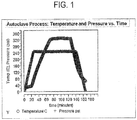
- the assembly was placed in an autoclave (Vacuum Press International Model Econoclave® 2X4, commercially available from ASC Process Systems), vacuum was drawn in the bag and the pressure and temperature of the autoclave were gradually raised based upon the temperature and pressure conditions summarized in FIG. 1 .
- the resulting densified TFE-VDF copolymer film was approximately 62.4 ⁇ m (microns) thick.
- the densified TFE-VDF copolymer film was then placed in a pantograph machine where the sheet was heated to a temperature of 370°C for a period of 90 seconds.
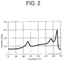
- FIG. 2 depicts a differential scanning calorimetry (DSC) scan showing the melt transition temperature peaks of the dense article, clearly indicating the presence of three peaks, the first peak at 177.73 C, the second peak at 341.83°C, and the third peak at 369.19°C.
- DSC differential scanning calorimetry
- the KMnO 4 solution was added at 4.6 mL/min for the next 1 kg of TFE.
- the KMnO 4 solution was then added at 50 mL/min until 1 kg more of TFE was consumed.
- the KMnO 4 solution was then added at 30 mL/min until 1 kg more of TFE was consumed.
- the KMnO 4 solution was then added at 40 mL/min until 1 kg more of TFE was consumed.
- the KMnO 4 solution was then added at 50 mL/min until 1 kg more of TFE was consumed.
- the KMnO 4 solution was then added at 25 mL/min until 1 kg more of TFE was consumed.
- the KMnO 4 solution was then added at 2 mL/min until 1 kg more of TFE was consumed.
- the total amount of KMnO 4 solution added was 5.725 kg.
- CTFE was pumped into the reactor via liquid feed using a syringe pump.
- CTFE and TFE were added after the first added 1 kg of TFE was consumed.
- CTFE and TFE were then added continuously such that for each 1 kg of consumed TFE there was 0.8L of CTFE consumed. This continued until a total of 3 kg of TFE was consumed and 1.6 L of CTFE was consumed.
- the polymerization continued by only feeding TFE until the end of the polymerization.
- the polymerization reaction stopped after 14.1 kg of TFE had been added to the reactor.
- the weight of the dispersion produced was 51.78 kg containing 35.61 % solids.
- the dispersion was coagulated with nitric acid and dried at 130°C.
- the raw dispersion particle size (RDPS) of the polymer particle was 0.266 ⁇ m (microns).
- the CTFE concentration in the copolymer was measured to be 13 mol% (15 wt %), as measured by nuclear magnetic resonance (NMR) spectroscopy.
- a dense article using the above described fine powder resin including the copolymer of TFE and CTFE was prepared as follows.
- the resin was mixed with Isopar® K (Exxon Mobil Corp., Fairfax, VA) at a concentration of 0.252 g/g of resin and formed into a pellet approximately 10.2 cm in diameter at a pressure of 2758 kPa.
- the pellet was heated to 49 °C and ram extruded into a tape having dimensions of 0.051 cm in thickness and 20.32 cm in width, through a die which affected a reduction ratio of 79 to 1, at an average extrusion pressure of 36804 kPa.
- the reduction ratio is the ratio of the cross sectional area of the extruder barrel to the cross sectional area of the extruded tape.
- the tape was dried by heating at 180 °C in order to remove the lubricant. The width of the dried tape was 18.1 cm.
- the tape was heated at 250°C for 120 seconds and then expanded in the longitudinal and transverse directions simultaneously at a ratio of 2.7: 1 in the longitudinal direction and 2.9: 1 in the transverse direction while maintaining a temperature of 250°C.
- the average engineering strain rate was calculated to be 700%/second.
- the resulting expanded TFE-CTFE copolymer film was densified as follows.
- One ply of the expanded TFE-CTFE copolymer film with a nominal thickness of 233.4 ⁇ m (micron) was placed between two caul plates in an autoclave bag assembled from polyimide film (Kapton® commercially available from DuPont deNemours, Wilmington, DE).
- the assembly was placed in an autoclave (Vacuum Press International Model Econoclave® 2X4, commercially available from ASC Process Systems), vacuum was drawn in the bag and the pressure and temperature of the autoclave were gradually raised based upon the temperature and pressure conditions summarized in FIG. 3 .
- the resulting densified TFE-CTFE copolymer film was approximately 46.7 ⁇ m (microns) thick.
- the densified TFE-CTFE copolymer film was then placed in a pantograph machine wherein the densified TFE copolymer film was heated to a temperature of 370° C for a period of 45 seconds.
- FIG. 4 depicts a differential scanning calorimetry (DSC) scan showing the melt transition temperature peaks of the dense article, clearly indicating the presence of three peaks, the first peak at 225.47°C, the second peak at 334.23°C, and the third peak at 373.82°C.
- DSC differential scanning calorimetry
- a dense article using the fine powder resin of Example 1 was prepared as follows.
- the resin was mixed with Isopar® K (Exxon Mobil Corp., Fairfax, VA) at a concentration of 0.201 g/g of resin and formed into a pellet approximately 10.2 cm in diameter at a pressure of 2758 kPa.
- the pellet was heated to 49 °C and ram extruded into a tape having dimensions of 0.064 cm in thickness and 20.32 cm in width, through a die which affected a reduction ratio of 63 to 1, at an average extrusion pressure of 72678 kPa.
- the reduction ratio is the ratio of the cross sectional area of the extruder barrel to the cross sectional area of the extruded tape.
- the tape was dried by heating at 130 °C in order to remove the lubricant. The width of the dried tape was 19.05 cm.
- the tape was heated at 200°C for 120 seconds and then expanded in the longitudinal and transverse directions simultaneously at a ratio of 3:1 in the longitudinal direction and 4.9:1 in the transverse direction while maintaining a temperature of 200°C.
- the average engineering strain rate was calculated to be 700%/second.
- the resulting expanded TFE-VDF copolymer film was densified as follows. One ply of the membrane with a nominal thickness of 181.0 ⁇ m (micron) was placed between two caul plates in an autoclave bag assembled from polyimide film (Kapton® commercially available from DuPont deNemours, Wilmington, DE). The assembly was placed in an autoclave (Vacuum Press International Model Econoclave® 2X4, commercially available from ASC Process Systems), vacuum was drawn in the bag, and the pressure and temperature of the autoclave were gradually raised based upon the temperature and pressure conditions summarized in FIG. 3 . The resulting densified TFE-VDF copolymer film was approximately 36.2 ⁇ m (microns) thick.
- the densified TFE-VDF copolymer film was characterized and the results are given in Table 1.
- the accumulation procedure described above under Methane Permeability was used to measure methane permeation.
- FIG. 5 includes differential scanning calorimetry (DSC) scans showing the melt transition temperature peaks of the densified TFE copolymer film, clearly indicating the presence of three peaks, the first peak at 176.51°C, the second peak at 343.87°C, and the third peak at 369.2°C.
- DSC differential scanning calorimetry
- a dense article using the fine powder resin of Example 2 was prepared as follows.
- the resin was mixed with Isopar® K (Exxon Mobil Corp., Fairfax, VA) at a concentration of 0.252 g/g of resin and formed into a pellet approximately 10.2 cm in diameter at a pressure of 2758 kPa.
- the pellet was heated to 49 °C and ram extruded into a tape having dimensions of 0.051 cm in thickness and 20.32 cm in width, through a die which affected a reduction ratio of 79 to 1, at an average extrusion pressure of 36804 kPa.
- the reduction ratio is the ratio of the cross sectional area of the extruder barrel to the cross sectional area of the extruded tape.
- the tape was dried by heating at 180 °C in order to remove the lubricant. The width of the dried tape was 18.1 cm.
- the tape was heated at 250°C for 120 seconds and then expanded in the longitudinal and transverse directions simultaneously at a ratio of 2.8:1 in the longitudinal direction and 4.5:1 in the transverse direction while maintaining a temperature of 250°C.
- the average engineering strain rate was calculated to be 700%/second.
- the resulting expanded TFE-CTFE copolymer film was densified as follows.
- One ply of the expanded TFE-CTFE copolymer film with a nominal thickness of 155.0 ⁇ m (microns) was placed between two caul plates in an autoclave bag assembled from polyimide film (Kapton® commercially available from DuPont deNemours, Wilmington, DE).
- the assembly was placed in an autoclave (Vacuum Press International Model Econoclave® 2X4, commercially available from ASC Process Systems), vacuum was drawn in the bag and the pressure and temperature of the autoclave were gradually raised based upon the temperature and pressure conditions summarized in FIG. 3 .
- the resulting densified TFE-CTFE copolymer film was approximately 31.0 ⁇ m (microns) thick.
- the densified TFE-CTFE copolymer was characterized and the results are given in Table 1.
- the accumulation procedure described above under Methane Permeability was used to measure methane permeation.
- FIG. 6 depicts a differential scanning calorimetry (DSC) scan showing the melt transition temperature peaks of the densified TFE-CTFE copolymer, clearly indicating the presence of three peaks, the first peak at 223.86°C, the second peak at 331.21°C and the third peak at 373.64°C.
- DSC differential scanning calorimetry
- a dense article using the fine powder resin comprising only PTFE was prepared as follows.
- the resin was mixed with Isopar® K (Exxon Mobil Corp., Fairfax, VA) at a concentration of 0.151 g/g of resin and formed into a pellet approximately 10.2 cm in diameter at a pressure of 2758 kPa.
- the pellet was heated to 49 °C and ram extruded into a tape having dimensions of 0.064 cm in thickness and 20.32 cm in width, through a die which affected a reduction ratio of 63 to 1, at an average extrusion pressure of 74463 kPa.
- the reduction ratio is the ratio of the cross sectional area of the extruder barrel to the cross sectional area of the extruded tape.
- the tape was dried by heating at 130 °C in order to remove the lubricant.
- the width of the dried tape was 19.05 cm.
- the tape was heated at 300°C for 120 seconds and then expanded in the longitudinal and transverse directions simultaneously at a ratio of 2.6:1 in the longitudinal direction and 2.8:1 in the transverse direction while maintaining a temperature of 300°C.
- the average engineering strain rate was calculated to be 100%/second.
- the resulting expanded PTFE membrane was densified as follows. One ply of the expanded PTFE membrane with a nominal thickness of 381.4 ⁇ m (micron) was placed between two caul plates in an autoclave bag assembled from polyimide film (Kapton® commercially available from DuPont deNemours, Wilmington, DE). The assembly was placed in an autoclave (Vacuum Press International Model Econoclave® 2X4, commercially available from ASC Process Systems), vacuum was drawn in the bag, and the pressure and temperature of the autoclave were gradually raised based upon the temperature and pressure conditions summarized in FIG. 7 . The resulting compressed ePTFE membrane was approximately 76.3 ⁇ m (microns) thick.
- the compressed ePTFE membrane was then placed in a pantograph machine where the compressed ePTFE membrane was heated to a temperature of 370° C for a period of 240 seconds.
- the compressed ePTFE membrane, while still heated, was then stretched in the longitudinal direction and transverse direction at a ratio of 2.95:1 and 1.5:1, respectively, at a rate of 5%/sec to form a dense PTFE article.
- FIG. 8 depicts a differential scanning calorimetry (DSC) scan showing the melt transition temperature peaks of the dense PTFE article, the first peak at 334.11 °C and the second peak at 371.96 °C.
- Table 1 Thickness ( ⁇ m) (micron) Methane Permeability normalized to thickness ( ⁇ g* ⁇ m/cm 2 /min) ( ⁇ g*micron/cm 2 /min) Void Volume (%) Matrix Tensile Strength (MPa) [psi] Matrix Tensile Strength (MPa) [psi] MD TD Example 1 19.72 0.208 1.402 229.3 [33261] 99.4 [14423] Example 2 14.53 0.149 6.160 183.0 [26539] 57.4 [8327] Example 3 36.19 0.268 13.77 81.5 [11826] 128.1 [18583] Example 4 30.99 0.029 10.19 43.8 [6348] 67.6 [9798] Comparative Example 17.47 0.609 2.658 26
Landscapes
- Health & Medical Sciences (AREA)
- Chemical & Material Sciences (AREA)
- General Health & Medical Sciences (AREA)
- Veterinary Medicine (AREA)
- Public Health (AREA)
- Epidemiology (AREA)
- Life Sciences & Earth Sciences (AREA)
- Animal Behavior & Ethology (AREA)
- Medicinal Chemistry (AREA)
- Chemical Kinetics & Catalysis (AREA)
- Organic Chemistry (AREA)
- Polymers & Plastics (AREA)
- Engineering & Computer Science (AREA)
- Oral & Maxillofacial Surgery (AREA)
- Vascular Medicine (AREA)
- Transplantation (AREA)
- Dermatology (AREA)
- Heart & Thoracic Surgery (AREA)
- Surgery (AREA)
- Mechanical Engineering (AREA)
- Manufacturing & Machinery (AREA)
- Dispersion Chemistry (AREA)
- Materials Engineering (AREA)
- Manufacture Of Macromolecular Shaped Articles (AREA)
- Laminated Bodies (AREA)
- Graft Or Block Polymers (AREA)
- Addition Polymer Or Copolymer, Post-Treatments, Or Chemical Modifications (AREA)
Claims (9)
- Procédé de fabrication d'un objet dense comprenant les étapes suivantes :densification d'un film de copolymère TFE comprenant un copolymère TFE à noyau/enveloppe pour former un objet dense, ledit film de copolymère TFE ayant une première endothermie entre 50 et 300 °C, une deuxième endothermie entre 320 °C et 350 °C, et une troisième endothermie entre 350 °C et 400 °C, les endothermies étant mesurées comme indiqué dans la description,ladite densification se faisant par compression à une température supérieure à 300 °C et pouvant atteindre 400 °C,le copolymère TFE à noyau/enveloppe ayant une partie enveloppe qui est faite uniquement de monomères TFE ou de monomères TFE et d'une quantité infime de comonomère et une partie noyau qui comprend du copolymère TFE,et ledit objet dense ayant un volume de vide, mesuré comme indiqué dans la description, inférieur à 20 %.
- Procédé selon la revendication 1 :- ledit film de copolymère TFE ayant une perméabilité au méthane, mesurée comme indiqué dans la description, inférieure à 20 µg*µm/cm2/min (µg*micron/cm2/min) ; ou- ladite densification se produisant à une température supérieure à ladite deuxième endothermie ou- ladite densification se produisant à une température comprise entre ladite deuxième endothermie et ladite troisième endothermie ; ou- ledit procédé comprenant en outre le traitement thermique dudit film de copolymère TFE à une température choisie parmi (1) une température inférieure à ladite première endothermie, (2) une température supérieure à ladite première endothermie, (3) une température supérieure à ladite deuxième endothermie, (4) une température comprise entre lesdites première et deuxième endothermies et (5) une température comprise entre lesdites deuxième et troisième endothermies avant ladite densification dudit film de copolymère TFE ; ou- ledit copolymère TFE comprenant :(a) une première partie noyau comprenant une chaîne polymère de monomères TFE et au moins un comonomère ; et(b) une seconde partie enveloppe comprenant une chaîne polymère composée uniquement de monomères TFE ou de monomères TFE et d'une quantité infime de copolymère,
ledit copolymère TFE à noyau/enveloppe comprenant au moins 3,0 % en poids de motifs polymérisés dudit au moins un comonomère par rapport au poids total dudit copolymère TFE. - Procédé de fabrication d'un objet dense comprenant les étapes suivantes :densification d'un film de copolymère TFE pour former un film de copolymère TFE dense, ledit film de copolymère TFE ayant une première endothermie entre 50 °C et 300 °C, une deuxième endothermie entre 320 °C et 350 °C, et une troisième endothermie entre 350 °C et 400 °C, les endothermies étant mesurées comme indiqué dans la description, etétirement dudit film de copolymère TFE dense pour former un objet dense,ladite densification se faisant par compression à une température supérieure à 300 °C et allant jusqu'à 400 °C,le copolymère TFE étant un copolymère TFE à noyau/enveloppe dans lequel une partie enveloppe est constituée uniquement de monomères TFE ou de monomères TFE et d'une quantité infime de comonomère et une partie noyau comprend le copolymère TFE etledit objet dense ayant un volume de vide, mesuré comme indiqué dans la description, inférieur à 20 %.
- Procédé selon la revendication 3 :- ledit film de copolymère TFE ayant une perméabilité au méthane, mesurée comme indiqué dans la description, inférieure à 20 µg*µm/cm2/min (µg*micron/cm2/min) ; ou- ledit étirement se produisant à une température comprise entre ladite première endothermie et une température allant jusqu'à 400 °C ; ou- ledit étirement se produisant à une température supérieure à ladite première endothermie ; ou- ledit étirement se produisant à une température supérieure à celle de ladite seconde endothermie ; ou- ledit étirement se produisant à une température comprise entre ladite première endothermie et ladite seconde endothermie ; ou- ledit étirement se produisant à une température comprise entre ladite deuxième endothermie et ladite troisième endothermie.
- Procédé selon la revendication 3, ladite densification se produisant à une température choisie parmi une température supérieure à ladite deuxième endothermie et une température comprise entre ladite deuxième et ladite troisième endothermie.
- Procédé selon la revendication 5, comprenant en outre le traitement thermique dudit film de copolymère TFE dense à une température choisie parmi(1) une température inférieure à ladite première endothermie, (2) une température supérieure à ladite première endothermie, (3) une température supérieure à ladite deuxième endothermie, (4) une température comprise entre lesdites première et deuxième endothermies et (5) une température comprise entre lesdites deuxième et troisième endothermies après ladite densification dudit film de copolymère TFE.
- Procédé selon la revendication 3, ledit étirement se produisant à une température choisie parmi (1) une température inférieure à ladite première endothermie, (2) une température supérieure à ladite première endothermie, (3) une température supérieure à ladite deuxième endothermie, (4) une température comprise entre ladite première et ladite deuxième endothermie et (5) une température comprise entre ladite deuxième et ladite troisième endothermie.
- Procédé selon la revendication 7, comprenant en outre le traitement thermique dudit film de copolymère TFE à une température choisie parmi (1) une température inférieure à ladite première endothermie, (2) une température supérieure à ladite première endothermie, (3) une température supérieure à ladite deuxième endothermie, (4) une température entre lesdites première et deuxième endothermies et (5) une température entre lesdites deuxième et troisième endothermies avant ledit étirement dudit film de copolymère TFE dense.
- Procédé selon la revendication 3, ledit copolymère TFE comprenant :(a) une première partie noyau comprenant une chaîne polymère de monomères TFE et au moins un comonomère ; et(b) une seconde partie enveloppe comprenant une chaîne polymère composée uniquement de monomères TFE ou de monomères TFE et d'une quantité infime de copolymère,
le copolymère TFE à noyau/enveloppe comprenant au moins 3,0 % en poids de motifs polymérisés dudit au moins un comonomère par rapport au poids total dudit copolymère TFE.
Applications Claiming Priority (2)
| Application Number | Priority Date | Filing Date | Title |
|---|---|---|---|
| US14/577,566 US9650479B2 (en) | 2007-10-04 | 2014-12-19 | Dense articles formed from tetrafluoroethylene core shell copolymers and methods of making the same |
| PCT/US2015/063603 WO2016099913A1 (fr) | 2014-12-19 | 2015-12-03 | Objets denses formés à partir de copolymères à noyau et enveloppe de tétrafluoroéthylène et leurs procédés de fabrication |
Publications (2)
| Publication Number | Publication Date |
|---|---|
| EP3233985A1 EP3233985A1 (fr) | 2017-10-25 |
| EP3233985B1 true EP3233985B1 (fr) | 2020-06-10 |
Family
ID=56127333
Family Applications (1)
| Application Number | Title | Priority Date | Filing Date |
|---|---|---|---|
| EP15816995.3A Active EP3233985B1 (fr) | 2014-12-19 | 2015-12-03 | Objets denses formés à partir de copolymères à noyau et enveloppe de tétrafluoroéthylène et leurs procédés de fabrication |
Country Status (7)
| Country | Link |
|---|---|
| EP (1) | EP3233985B1 (fr) |
| JP (1) | JP6431201B2 (fr) |
| KR (1) | KR102014625B1 (fr) |
| CN (1) | CN107106730B (fr) |
| AU (1) | AU2015363139B2 (fr) |
| CA (1) | CA2967848C (fr) |
| WO (1) | WO2016099913A1 (fr) |
Families Citing this family (5)
| Publication number | Priority date | Publication date | Assignee | Title |
|---|---|---|---|---|
| US9644054B2 (en) * | 2014-12-19 | 2017-05-09 | W. L. Gore & Associates, Inc. | Dense articles formed from tetrafluoroethylene core shell copolymers and methods of making the same |
| JP7657022B2 (ja) | 2017-04-11 | 2025-04-04 | ソルベイ スペシャルティ ポリマーズ イタリー エス.ピー.エー. | フルオロポリマーの製造方法 |
| WO2020040024A1 (fr) * | 2018-08-24 | 2020-02-27 | Agc株式会社 | Procédé de fabrication de film, film, corps stratifié, et matériau d'emballage |
| CN113337057B (zh) * | 2021-05-28 | 2022-11-04 | 蚌埠壹石通聚合物复合材料有限公司 | 一种ptfe复合粉体、制备方法及含有该粉体的复合材料 |
| JP2024531512A (ja) * | 2021-08-30 | 2024-08-29 | ダブリュ.エル.ゴア アンド アソシエイツ,インコーポレイティド | 調整可能なヘイズ及び色を有する、高透過性ptfe高密度フィルム |
Family Cites Families (7)
| Publication number | Priority date | Publication date | Assignee | Title |
|---|---|---|---|---|
| CA962021A (en) | 1970-05-21 | 1975-02-04 | Robert W. Gore | Porous products and process therefor |
| JP2729837B2 (ja) * | 1988-07-25 | 1998-03-18 | 旭化成工業株式会社 | ポリテトラフルオロエチレン糸状物及びその製造法 |
| US5374473A (en) | 1992-08-19 | 1994-12-20 | W. L. Gore & Associates, Inc. | Dense polytetrafluoroethylene articles |
| US20050238872A1 (en) * | 2004-04-23 | 2005-10-27 | Kennedy Michael E | Fluoropolymer barrier material |
| US9040646B2 (en) * | 2007-10-04 | 2015-05-26 | W. L. Gore & Associates, Inc. | Expandable TFE copolymers, methods of making, and porous, expanded articles thereof |
| US8637144B2 (en) * | 2007-10-04 | 2014-01-28 | W. L. Gore & Associates, Inc. | Expandable TFE copolymers, method of making, and porous, expended articles thereof |
| EP3194490B1 (fr) * | 2014-09-17 | 2018-01-31 | ExxonMobil Chemical Patents Inc. | Composition elastomeric pour pneumatiques comprenant des resins hydrocarbonées a temperature vitreuse elevée |
-
2015
- 2015-12-03 KR KR1020177020021A patent/KR102014625B1/ko active Active
- 2015-12-03 JP JP2017533303A patent/JP6431201B2/ja active Active
- 2015-12-03 CA CA2967848A patent/CA2967848C/fr active Active
- 2015-12-03 EP EP15816995.3A patent/EP3233985B1/fr active Active
- 2015-12-03 CN CN201580069470.6A patent/CN107106730B/zh active Active
- 2015-12-03 AU AU2015363139A patent/AU2015363139B2/en active Active
- 2015-12-03 WO PCT/US2015/063603 patent/WO2016099913A1/fr not_active Ceased
Non-Patent Citations (1)
| Title |
|---|
| None * |
Also Published As
| Publication number | Publication date |
|---|---|
| CN107106730A (zh) | 2017-08-29 |
| EP3233985A1 (fr) | 2017-10-25 |
| CA2967848A1 (fr) | 2016-06-23 |
| CA2967848C (fr) | 2020-01-21 |
| CN107106730B (zh) | 2020-12-25 |
| KR20170096176A (ko) | 2017-08-23 |
| KR102014625B1 (ko) | 2019-08-26 |
| JP6431201B2 (ja) | 2018-11-28 |
| AU2015363139B2 (en) | 2018-03-01 |
| AU2015363139A1 (en) | 2017-05-25 |
| WO2016099913A1 (fr) | 2016-06-23 |
| JP2018501370A (ja) | 2018-01-18 |
Similar Documents
| Publication | Publication Date | Title |
|---|---|---|
| EP2408827B1 (fr) | Copolymères de tfe expansibles, leur procédé de fabrication et articles poreux expansibles formés à partir de ces copolymères | |
| AU2019272051B2 (en) | Articles produced from VDF-co-(TFE or TrFE) polymers | |
| US9988506B2 (en) | Dense articles formed tetrafluoroethylene core shell copolymers and methods of making the same | |
| AU2015363139B2 (en) | Dense articles formed from tetrafluoroethylene core shell copolymers and methods of making the same | |
| EP3233987B1 (fr) | Articles denses formés à partir de copolymères de tétrafluroéthylène type coeur-écorce et leurs procédés de fabrication | |
| HK1243721A1 (en) | Dense articles formed from tetrafluoroethylene core shell copolymers and methods of making the same | |
| HK1243721B (en) | Dense articles formed from tetrafluoroethylene core shell copolymers and methods of making the same | |
| HK1244025B (en) | Dense articles formed from tetrafluroethylene core shell copolymers and methods of making the same |
Legal Events
| Date | Code | Title | Description |
|---|---|---|---|
| STAA | Information on the status of an ep patent application or granted ep patent |
Free format text: STATUS: THE INTERNATIONAL PUBLICATION HAS BEEN MADE |
|
| PUAI | Public reference made under article 153(3) epc to a published international application that has entered the european phase |
Free format text: ORIGINAL CODE: 0009012 |
|
| STAA | Information on the status of an ep patent application or granted ep patent |
Free format text: STATUS: REQUEST FOR EXAMINATION WAS MADE |
|
| 17P | Request for examination filed |
Effective date: 20170524 |
|
| AK | Designated contracting states |
Kind code of ref document: A1 Designated state(s): AL AT BE BG CH CY CZ DE DK EE ES FI FR GB GR HR HU IE IS IT LI LT LU LV MC MK MT NL NO PL PT RO RS SE SI SK SM TR |
|
| AX | Request for extension of the european patent |
Extension state: BA ME |
|
| DAV | Request for validation of the european patent (deleted) | ||
| DAX | Request for extension of the european patent (deleted) | ||
| REG | Reference to a national code |
Ref country code: HK Ref legal event code: DE Ref document number: 1243721 Country of ref document: HK |
|
| STAA | Information on the status of an ep patent application or granted ep patent |
Free format text: STATUS: EXAMINATION IS IN PROGRESS |
|
| 17Q | First examination report despatched |
Effective date: 20190904 |
|
| GRAP | Despatch of communication of intention to grant a patent |
Free format text: ORIGINAL CODE: EPIDOSNIGR1 |
|
| STAA | Information on the status of an ep patent application or granted ep patent |
Free format text: STATUS: GRANT OF PATENT IS INTENDED |
|
| RIC1 | Information provided on ipc code assigned before grant |
Ipc: A61L 27/16 20060101ALI20200114BHEP Ipc: A61L 27/50 20060101ALI20200114BHEP Ipc: A61L 31/14 20060101ALI20200114BHEP Ipc: B29C 55/00 20060101ALI20200114BHEP Ipc: C08J 5/18 20060101AFI20200114BHEP Ipc: A61L 27/26 20060101ALI20200114BHEP Ipc: C08J 9/00 20060101ALI20200114BHEP Ipc: A61L 29/08 20060101ALI20200114BHEP Ipc: C08F 214/26 20060101ALI20200114BHEP Ipc: A61L 31/04 20060101ALI20200114BHEP Ipc: A61L 31/10 20060101ALI20200114BHEP Ipc: A61L 29/04 20060101ALI20200114BHEP Ipc: A61L 27/34 20060101ALI20200114BHEP Ipc: C08F 259/08 20060101ALI20200114BHEP Ipc: A61L 27/56 20060101ALI20200114BHEP Ipc: B29C 44/56 20060101ALI20200114BHEP |
|
| INTG | Intention to grant announced |
Effective date: 20200129 |
|
| RIN1 | Information on inventor provided before grant (corrected) |
Inventor name: FORD, LAWRENCE, A. Inventor name: SAYLER, TODD, S. Inventor name: SHAFER, GREGORY, J. Inventor name: RAN, SHAOFENG Inventor name: KENNEDY, MICHAEL, E. |
|
| GRAS | Grant fee paid |
Free format text: ORIGINAL CODE: EPIDOSNIGR3 |
|
| GRAA | (expected) grant |
Free format text: ORIGINAL CODE: 0009210 |
|
| STAA | Information on the status of an ep patent application or granted ep patent |
Free format text: STATUS: THE PATENT HAS BEEN GRANTED |
|
| AK | Designated contracting states |
Kind code of ref document: B1 Designated state(s): AL AT BE BG CH CY CZ DE DK EE ES FI FR GB GR HR HU IE IS IT LI LT LU LV MC MK MT NL NO PL PT RO RS SE SI SK SM TR |
|
| REG | Reference to a national code |
Ref country code: GB Ref legal event code: FG4D |
|
| REG | Reference to a national code |
Ref country code: CH Ref legal event code: EP Ref country code: AT Ref legal event code: REF Ref document number: 1279149 Country of ref document: AT Kind code of ref document: T Effective date: 20200615 |
|
| REG | Reference to a national code |
Ref country code: DE Ref legal event code: R096 Ref document number: 602015054141 Country of ref document: DE |
|
| REG | Reference to a national code |
Ref country code: IE Ref legal event code: FG4D |
|
| REG | Reference to a national code |
Ref country code: NL Ref legal event code: FP |
|
| REG | Reference to a national code |
Ref country code: LT Ref legal event code: MG4D |
|
| PG25 | Lapsed in a contracting state [announced via postgrant information from national office to epo] |
Ref country code: NO Free format text: LAPSE BECAUSE OF FAILURE TO SUBMIT A TRANSLATION OF THE DESCRIPTION OR TO PAY THE FEE WITHIN THE PRESCRIBED TIME-LIMIT Effective date: 20200910 Ref country code: GR Free format text: LAPSE BECAUSE OF FAILURE TO SUBMIT A TRANSLATION OF THE DESCRIPTION OR TO PAY THE FEE WITHIN THE PRESCRIBED TIME-LIMIT Effective date: 20200911 Ref country code: FI Free format text: LAPSE BECAUSE OF FAILURE TO SUBMIT A TRANSLATION OF THE DESCRIPTION OR TO PAY THE FEE WITHIN THE PRESCRIBED TIME-LIMIT Effective date: 20200610 Ref country code: SE Free format text: LAPSE BECAUSE OF FAILURE TO SUBMIT A TRANSLATION OF THE DESCRIPTION OR TO PAY THE FEE WITHIN THE PRESCRIBED TIME-LIMIT Effective date: 20200610 Ref country code: LT Free format text: LAPSE BECAUSE OF FAILURE TO SUBMIT A TRANSLATION OF THE DESCRIPTION OR TO PAY THE FEE WITHIN THE PRESCRIBED TIME-LIMIT Effective date: 20200610 |
|
| PG25 | Lapsed in a contracting state [announced via postgrant information from national office to epo] |
Ref country code: BG Free format text: LAPSE BECAUSE OF FAILURE TO SUBMIT A TRANSLATION OF THE DESCRIPTION OR TO PAY THE FEE WITHIN THE PRESCRIBED TIME-LIMIT Effective date: 20200910 Ref country code: HR Free format text: LAPSE BECAUSE OF FAILURE TO SUBMIT A TRANSLATION OF THE DESCRIPTION OR TO PAY THE FEE WITHIN THE PRESCRIBED TIME-LIMIT Effective date: 20200610 Ref country code: LV Free format text: LAPSE BECAUSE OF FAILURE TO SUBMIT A TRANSLATION OF THE DESCRIPTION OR TO PAY THE FEE WITHIN THE PRESCRIBED TIME-LIMIT Effective date: 20200610 Ref country code: RS Free format text: LAPSE BECAUSE OF FAILURE TO SUBMIT A TRANSLATION OF THE DESCRIPTION OR TO PAY THE FEE WITHIN THE PRESCRIBED TIME-LIMIT Effective date: 20200610 |
|
| REG | Reference to a national code |
Ref country code: AT Ref legal event code: MK05 Ref document number: 1279149 Country of ref document: AT Kind code of ref document: T Effective date: 20200610 |
|
| PG25 | Lapsed in a contracting state [announced via postgrant information from national office to epo] |
Ref country code: AL Free format text: LAPSE BECAUSE OF FAILURE TO SUBMIT A TRANSLATION OF THE DESCRIPTION OR TO PAY THE FEE WITHIN THE PRESCRIBED TIME-LIMIT Effective date: 20200610 |
|
| PG25 | Lapsed in a contracting state [announced via postgrant information from national office to epo] |
Ref country code: AT Free format text: LAPSE BECAUSE OF FAILURE TO SUBMIT A TRANSLATION OF THE DESCRIPTION OR TO PAY THE FEE WITHIN THE PRESCRIBED TIME-LIMIT Effective date: 20200610 Ref country code: EE Free format text: LAPSE BECAUSE OF FAILURE TO SUBMIT A TRANSLATION OF THE DESCRIPTION OR TO PAY THE FEE WITHIN THE PRESCRIBED TIME-LIMIT Effective date: 20200610 Ref country code: SM Free format text: LAPSE BECAUSE OF FAILURE TO SUBMIT A TRANSLATION OF THE DESCRIPTION OR TO PAY THE FEE WITHIN THE PRESCRIBED TIME-LIMIT Effective date: 20200610 Ref country code: PT Free format text: LAPSE BECAUSE OF FAILURE TO SUBMIT A TRANSLATION OF THE DESCRIPTION OR TO PAY THE FEE WITHIN THE PRESCRIBED TIME-LIMIT Effective date: 20201012 Ref country code: CZ Free format text: LAPSE BECAUSE OF FAILURE TO SUBMIT A TRANSLATION OF THE DESCRIPTION OR TO PAY THE FEE WITHIN THE PRESCRIBED TIME-LIMIT Effective date: 20200610 Ref country code: IT Free format text: LAPSE BECAUSE OF FAILURE TO SUBMIT A TRANSLATION OF THE DESCRIPTION OR TO PAY THE FEE WITHIN THE PRESCRIBED TIME-LIMIT Effective date: 20200610 Ref country code: ES Free format text: LAPSE BECAUSE OF FAILURE TO SUBMIT A TRANSLATION OF THE DESCRIPTION OR TO PAY THE FEE WITHIN THE PRESCRIBED TIME-LIMIT Effective date: 20200610 Ref country code: RO Free format text: LAPSE BECAUSE OF FAILURE TO SUBMIT A TRANSLATION OF THE DESCRIPTION OR TO PAY THE FEE WITHIN THE PRESCRIBED TIME-LIMIT Effective date: 20200610 |
|
| PG25 | Lapsed in a contracting state [announced via postgrant information from national office to epo] |
Ref country code: PL Free format text: LAPSE BECAUSE OF FAILURE TO SUBMIT A TRANSLATION OF THE DESCRIPTION OR TO PAY THE FEE WITHIN THE PRESCRIBED TIME-LIMIT Effective date: 20200610 Ref country code: SK Free format text: LAPSE BECAUSE OF FAILURE TO SUBMIT A TRANSLATION OF THE DESCRIPTION OR TO PAY THE FEE WITHIN THE PRESCRIBED TIME-LIMIT Effective date: 20200610 Ref country code: IS Free format text: LAPSE BECAUSE OF FAILURE TO SUBMIT A TRANSLATION OF THE DESCRIPTION OR TO PAY THE FEE WITHIN THE PRESCRIBED TIME-LIMIT Effective date: 20201010 |
|
| REG | Reference to a national code |
Ref country code: DE Ref legal event code: R097 Ref document number: 602015054141 Country of ref document: DE |
|
| PLBE | No opposition filed within time limit |
Free format text: ORIGINAL CODE: 0009261 |
|
| STAA | Information on the status of an ep patent application or granted ep patent |
Free format text: STATUS: NO OPPOSITION FILED WITHIN TIME LIMIT |
|
| PG25 | Lapsed in a contracting state [announced via postgrant information from national office to epo] |
Ref country code: DK Free format text: LAPSE BECAUSE OF FAILURE TO SUBMIT A TRANSLATION OF THE DESCRIPTION OR TO PAY THE FEE WITHIN THE PRESCRIBED TIME-LIMIT Effective date: 20200610 |
|
| 26N | No opposition filed |
Effective date: 20210311 |
|
| PG25 | Lapsed in a contracting state [announced via postgrant information from national office to epo] |
Ref country code: SI Free format text: LAPSE BECAUSE OF FAILURE TO SUBMIT A TRANSLATION OF THE DESCRIPTION OR TO PAY THE FEE WITHIN THE PRESCRIBED TIME-LIMIT Effective date: 20200610 |
|
| REG | Reference to a national code |
Ref country code: CH Ref legal event code: PL |
|
| PG25 | Lapsed in a contracting state [announced via postgrant information from national office to epo] |
Ref country code: MC Free format text: LAPSE BECAUSE OF FAILURE TO SUBMIT A TRANSLATION OF THE DESCRIPTION OR TO PAY THE FEE WITHIN THE PRESCRIBED TIME-LIMIT Effective date: 20200610 |
|
| PG25 | Lapsed in a contracting state [announced via postgrant information from national office to epo] |
Ref country code: IE Free format text: LAPSE BECAUSE OF NON-PAYMENT OF DUE FEES Effective date: 20201203 Ref country code: LU Free format text: LAPSE BECAUSE OF NON-PAYMENT OF DUE FEES Effective date: 20201203 |
|
| PG25 | Lapsed in a contracting state [announced via postgrant information from national office to epo] |
Ref country code: CH Free format text: LAPSE BECAUSE OF NON-PAYMENT OF DUE FEES Effective date: 20201231 Ref country code: LI Free format text: LAPSE BECAUSE OF NON-PAYMENT OF DUE FEES Effective date: 20201231 |
|
| PG25 | Lapsed in a contracting state [announced via postgrant information from national office to epo] |
Ref country code: TR Free format text: LAPSE BECAUSE OF FAILURE TO SUBMIT A TRANSLATION OF THE DESCRIPTION OR TO PAY THE FEE WITHIN THE PRESCRIBED TIME-LIMIT Effective date: 20200610 Ref country code: MT Free format text: LAPSE BECAUSE OF FAILURE TO SUBMIT A TRANSLATION OF THE DESCRIPTION OR TO PAY THE FEE WITHIN THE PRESCRIBED TIME-LIMIT Effective date: 20200610 Ref country code: CY Free format text: LAPSE BECAUSE OF FAILURE TO SUBMIT A TRANSLATION OF THE DESCRIPTION OR TO PAY THE FEE WITHIN THE PRESCRIBED TIME-LIMIT Effective date: 20200610 |
|
| PG25 | Lapsed in a contracting state [announced via postgrant information from national office to epo] |
Ref country code: MK Free format text: LAPSE BECAUSE OF FAILURE TO SUBMIT A TRANSLATION OF THE DESCRIPTION OR TO PAY THE FEE WITHIN THE PRESCRIBED TIME-LIMIT Effective date: 20200610 |
|
| P01 | Opt-out of the competence of the unified patent court (upc) registered |
Effective date: 20230511 |
|
| PGFP | Annual fee paid to national office [announced via postgrant information from national office to epo] |
Ref country code: NL Payment date: 20241121 Year of fee payment: 10 |
|
| PGFP | Annual fee paid to national office [announced via postgrant information from national office to epo] |
Ref country code: DE Payment date: 20241121 Year of fee payment: 10 |
|
| PGFP | Annual fee paid to national office [announced via postgrant information from national office to epo] |
Ref country code: BE Payment date: 20241121 Year of fee payment: 10 |
|
| PGFP | Annual fee paid to national office [announced via postgrant information from national office to epo] |
Ref country code: GB Payment date: 20241122 Year of fee payment: 10 |
|
| PGFP | Annual fee paid to national office [announced via postgrant information from national office to epo] |
Ref country code: FR Payment date: 20241121 Year of fee payment: 10 |