EP3234564B1 - Methode de calibration d'appareil de mesure de la concentration de creatinine - Google Patents
Methode de calibration d'appareil de mesure de la concentration de creatinine Download PDFInfo
- Publication number
- EP3234564B1 EP3234564B1 EP15810663.3A EP15810663A EP3234564B1 EP 3234564 B1 EP3234564 B1 EP 3234564B1 EP 15810663 A EP15810663 A EP 15810663A EP 3234564 B1 EP3234564 B1 EP 3234564B1
- Authority
- EP
- European Patent Office
- Prior art keywords
- temperature
- crn
- concentrations
- time
- calibration solutions
- Prior art date
- Legal status (The legal status is an assumption and is not a legal conclusion. Google has not performed a legal analysis and makes no representation as to the accuracy of the status listed.)
- Active
Links
Images


Classifications
-
- G—PHYSICS
- G01—MEASURING; TESTING
- G01N—INVESTIGATING OR ANALYSING MATERIALS BY DETERMINING THEIR CHEMICAL OR PHYSICAL PROPERTIES
- G01N27/00—Investigating or analysing materials by the use of electric, electrochemical, or magnetic means
- G01N27/26—Investigating or analysing materials by the use of electric, electrochemical, or magnetic means by investigating electrochemical variables; by using electrolysis or electrophoresis
- G01N27/28—Electrolytic cell components
- G01N27/30—Electrodes, e.g. test electrodes; Half-cells
- G01N27/327—Biochemical electrodes, e.g. electrical or mechanical details for in vitro measurements
- G01N27/3271—Amperometric enzyme electrodes for analytes in body fluids, e.g. glucose in blood
- G01N27/3274—Corrective measures, e.g. error detection, compensation for temperature or hematocrit, calibration
-
- C—CHEMISTRY; METALLURGY
- C12—BIOCHEMISTRY; BEER; SPIRITS; WINE; VINEGAR; MICROBIOLOGY; ENZYMOLOGY; MUTATION OR GENETIC ENGINEERING
- C12Q—MEASURING OR TESTING PROCESSES INVOLVING ENZYMES, NUCLEIC ACIDS OR MICROORGANISMS; COMPOSITIONS OR TEST PAPERS THEREFOR; PROCESSES OF PREPARING SUCH COMPOSITIONS; CONDITION-RESPONSIVE CONTROL IN MICROBIOLOGICAL OR ENZYMOLOGICAL PROCESSES
- C12Q1/00—Measuring or testing processes involving enzymes, nucleic acids or microorganisms; Compositions therefor; Processes of preparing such compositions
- C12Q1/001—Enzyme electrodes
- C12Q1/005—Enzyme electrodes involving specific analytes or enzymes
-
- G—PHYSICS
- G01—MEASURING; TESTING
- G01N—INVESTIGATING OR ANALYSING MATERIALS BY DETERMINING THEIR CHEMICAL OR PHYSICAL PROPERTIES
- G01N33/00—Investigating or analysing materials by specific methods not covered by groups G01N1/00 - G01N31/00
- G01N33/48—Biological material, e.g. blood, urine; Haemocytometers
- G01N33/50—Chemical analysis of biological material, e.g. blood, urine; Testing involving biospecific ligand binding methods; Immunological testing
- G01N33/70—Chemical analysis of biological material, e.g. blood, urine; Testing involving biospecific ligand binding methods; Immunological testing involving creatine or creatinine
-
- G—PHYSICS
- G01—MEASURING; TESTING
- G01N—INVESTIGATING OR ANALYSING MATERIALS BY DETERMINING THEIR CHEMICAL OR PHYSICAL PROPERTIES
- G01N2333/00—Assays involving biological materials from specific organisms or of a specific nature
- G01N2333/90—Enzymes; Proenzymes
- G01N2333/902—Oxidoreductases (1.)
- G01N2333/906—Oxidoreductases (1.) acting on nitrogen containing compounds as donors (1.4, 1.5, 1.7)
- G01N2333/9065—Oxidoreductases (1.) acting on nitrogen containing compounds as donors (1.4, 1.5, 1.7) acting on CH-NH groups of donors (1.5)
- G01N2333/90672—Oxidoreductases (1.) acting on nitrogen containing compounds as donors (1.4, 1.5, 1.7) acting on CH-NH groups of donors (1.5) with oxygen as acceptor (1.5.3) in general
- G01N2333/90677—Oxidoreductases (1.) acting on nitrogen containing compounds as donors (1.4, 1.5, 1.7) acting on CH-NH groups of donors (1.5) with oxygen as acceptor (1.5.3) in general with a definite EC number (1.5.3.-)
- G01N2333/90683—Sarcosine oxidase (1.5.3.1)
-
- G—PHYSICS
- G01—MEASURING; TESTING
- G01N—INVESTIGATING OR ANALYSING MATERIALS BY DETERMINING THEIR CHEMICAL OR PHYSICAL PROPERTIES
- G01N2333/00—Assays involving biological materials from specific organisms or of a specific nature
- G01N2333/90—Enzymes; Proenzymes
- G01N2333/914—Hydrolases (3)
- G01N2333/978—Hydrolases (3) acting on carbon to nitrogen bonds other than peptide bonds (3.5)
- G01N2333/986—Hydrolases (3) acting on carbon to nitrogen bonds other than peptide bonds (3.5) acting on amide bonds in cyclic amides (3.5.2), e.g. beta-lactamase (penicillinase, 3.5.2.6), creatinine amidohydrolase (creatininase, EC 3.5.2.10), N-methylhydantoinase (3.5.2.6)
Definitions
- the invention relates to methods for calibrating creatinine measuring devices, and calibration solutions for use in those methods.
- the concentration of Cr (cCr) and the concentration of Crn (cCrn) in an aqueous solution can be determined by amperometric measurement.
- Two sensors are used in the measurement of cCrn: the Crea A sensor, which detects Cr; and the Crea B sensor, which detects both Cr and Crn.
- the cCrn is based on the difference between the Crea A and Crea B sensor measurements.
- the Crea A and Crea B sensors In order to determine cCrn in unknown samples with sufficient accuracy, the Crea A and Crea B sensors must be calibrated regularly in order to determine their actual sensitivities.
- the sensors can be calibrated using two aqueous calibration solutions of known cCrn and cCr.
- a problem with such calibration solutions is that cCr and cCrn are not fixed. Rather, when in aqueous solution, Crn can be converted into Cr and vice versa by water hydrolysis and elimination respectively, as indicated by the double arrow in the reaction equation in Scheme 1, where T is the temperature at which the reaction occurs and k 1 and k 2 are the rate constants for the hydrolysis and elimination reactions respectively.
- a calibration solution having known cCr and cCrn in equilibrium ratios can be generated by adding the enzyme creatinine amidohydrolase (CA) to a solution of known sum concentration of Cr and Crn, and then allow that solution to equilibrate by maintaining the solution at a specific temperature for about one hour.
- the CA facilitates equilibration.
- the cCr and cCrn can be determined simply by reference to the known equilibrium constants at the given temperature.
- WO 2005/052596 discloses a reference solution for quality control on a medical analyser and a kit for holding the reference solution.
- the kit comprises a container with a first and a second compartment, wherein the first and the second compartment may be separated by a thin wall, which may be broken upon exertion of manual pressure, which will cause the liquids of the first and second compartments to mix.
- the first compartment comprises a buffer
- the second compartment comprises two chemical compounds and a catalyst. When the two compounds, the catalyst and the buffer is mixed, a thermodynamic equilibrium is reached more rapidly allowing the solution to be used as quality control reference solution within hours, when conditioned at 25 °C, whereas the solution would otherwise have to be conditioned for much longer, if no catalyst was used.
- Calibration solutions having known cCr and cCrn in non-equilibrium ratios can be prepared by dissolving a known quantity of dry powder containing known quantities of Cr and Crn in a known volume of water, or other aqueous medium.
- the calibration solution is kept at between 15°C to 32°C, which allows for accurate calculations for solutions less than 14 days old, even when approximating this to be at a constant temperature. Therefore, existing methods are sufficiently accurate to enable the calculation of cCr and cCrn for calibration solutions having a short usage period (i.e. t age ⁇ 14 days).
- Another alternative is to produce an acidic creatinine solution, this is thermodynamically stable and can thus be maintained during storage.
- This solution can then be mixed with a buffer-solution immediately before use to obtain a calibration solution of essentially pure Crn with a known pH and cCrn, such as disclosed in US 2004/0072277 .
- a problem with this approach is that it is difficult to produce a homogeneous mixture if the two solutions are contained in sealed airtight pouches. Additionally, the mixing process will also require pumping means if automatic mixing is required and/or if the pouches are part of a closed system, such as a cassette based solution pack.
- US 2012/181189 A1 describes an amperometric biosensor for determination of creatinine in a sample fluid.
- US 2004/072277 A1 describes a method for calibrating a biosensor for the amperometric determination of creatinine in biological liquids, consisting of one electrode system each for measuring the concentration of creatinine and creatine.
- ABL800 FLEX Operator's Manual describes the ABL800 FLEX analyzers.
- ABL800 FLEX Reference Manual describes the ABL800 FLEX analyzers.
- the applicant makes available a method of calibrating a device for measuring the concentration of creatinine using one or more calibration solutions, the method comprising: receiving concentrations at an initial time of creatine, Cr, and/or creatinine, Crn, of the one or more calibration solutions; receiving outputs of the measuring device at the end time; calculating the concentration of Cr and/or Crn in the calibration solutions at an end time using a temperature model, wherein the temperature model indicates changes in temperature of the calibration solutions from the initial time to the end time; and determining a relationship between the outputs of the measuring device and the calculated concentrations of Cr and/or Crn.
- the method is as defined in claim 1.
- the measuring device includes a sensor for measuring creatine and/or a sensor for measuring creatinine in one or more of the calibration solutions.
- the measuring device includes a sensor for measuring creatine and creatinine in one or more of the calibration solutions.
- the measuring device is an amperometric measuring device.
- the method further comprises determining the temperature model by receiving measurements of the changes in temperature of the calibration solutions from a temperature probe from the initial time to the end time.
- the received measurements are recorded measurements.
- said determining the temperature model comprises calibrating the received measurements of the changes in temperature with a second temperature probe.
- the determining a relationship between the measuring device outputs and the calculated concentrations of Cr and Crn comprises calculating sensor sensitivities of the measuring devices.
- the method further comprises receiving temperature measurements after the end time and updating the calculated sensitivities of the measuring devices using the temperature measurements received after the end time.
- the end time is greater than 14 days after the initial time.
- a computer readable medium comprising instructions which when executed by one or more processors of an electronic device, cause the electronic device to operate any of the aforementioned methods.
- an electronic device comprising: one or more processors; and memory comprising instructions which when executed by one or more of the processors cause the electronic device to operate any of the aforementioned methods.
- a package comprising one or more calibration solutions, the package being suitable for use with any of the aforementioned methods or aforementioned electronic devices.
- the package further comprises an indication of the initial time and the concentrations at the initial time of creatine (Cr) and/or creatinine (Crn) of the one or more calibration solutions.
- the package further comprises a temperature probe for measuring the temperatures of the creatinine solutions from the initial time to the end time, and memory for storing the measured temperatures.
- FIG. 1 is a schematic diagram of a three-electrode amperometric measuring system 101.
- An amperometric measuring system may have at least two electrodes: a working electrode (WE) 110 and a combined counter and reference electrode (CE/RE).
- WE working electrode
- CE/RE combined counter and reference electrode
- the functions of the CE/RE electrode are split into two separate electrodes: the reference electrode (RE) 111 and the counter electrode (CE) 112.
- the example amperometric measuring system 101 also includes an ammeter 120, a voltmeter 121 and a voltage source 122 and the electrolyte solution 140.
- the WE 110 is a positively charged electrode where an oxidation reaction occurs.
- the RE 111 is typically made of Ag/AgCl and is able to maintain a stable potential, especially if no current runs through it, thus the need for a CE 112 for passing the current from the WE 110 back to the electrolyte solution 140.
- the electrolyte solution 140 / sample provides a current path between the three electrodes.
- the membrane 130 selectively converts the analyte to a substance that selectively is allowed to pass through from the sample 150.
- the voltage source 122 applies the necessary potential for maintaining the desired reduction or oxidation reaction, this is controlled by the voltmeter 121.
- the ammeter 120 measures the resulting current flowing through the electrical circuit.
- amperometric measuring system shown in Figure 1 is an illustrative example, and several other implementations are envisioned.
- the amperometric measuring system could be a two electrode system as mentioned above.
- the magnitude of an electrical current flowing through the electrode chain is proportional to the concentration of the substance being oxidized (or reduced) at the WE 110.
- the concentration in any given sample can be obtained by measuring the electrical current generated by that particular sample.
- the sample 150 contains species B which, in the membrane 130, is selectively converted to species A, which can be oxidized at the WE 110 (WE) to A + , and the electrolyte 140 contains species X which is reduced at the CE 112 (cathode) to X - .
- WE WE 110
- CE 112 cathode
- A is oxidized at the WE 110 according to the following reaction: A ⁇ A + + e ⁇
- the magnitude of the current flowing through the circuit is proportional to the concentration of the analyte being oxidized.
- the analyser can therefore automatically calculate the concentration of the analyte in the sample given species X is in excess.
- the term sensor refers to a complete amperometric measuring system, as shown in Figure 1 excluding the sample 150.
- Crn is not stable in aqueous solutions, e.g. blood, where it is reversibly converted into Cr (see Scheme 1).
- the example utilizes a two-sensor system where one sensor (Crea A) detects Cr only, and the other sensor (Crea B) detects both Cr and Crn. By means of a difference measurement it is possible to obtain the cCrn value.
- the sensor is protected by a multilayer membrane 130 consisting of at least three functional layers, namely the outer membrane layer permeable to Crn and Cr; the middle enzyme layer, and the inner membrane layer permeable to H 2 O 2 .
- the enzymes creatinine amidohydrolase, creatine amidinohydrolase and sarcosine oxidase are immobilized between the inner and outer membrane layers.
- the Crea A sensor contains only creatine amidinohydrolase and sarcosine oxidase, and so detects only Cr.
- the enzymatic cascade changes Cr as follows: Creatine + H 2 O ⁇ sarcosine + urea (creatine amidinohydrolase) Sarcosine + H 2 O + O 2 ⁇ glycine + formaldehyde + H 2 O 2 (sarcosine oxidase)
- the Crea B sensor contains all three enzymes creatinine amidohydrolase, creatine amidinohydrolase and sarcosine oxidase, and so detects both Crn and Cr.
- Crn/Cr changes as follows: Creatinine + H 2 O ⁇ creatine (creatinine amidohydrolase) Creatine + H 2 O ⁇ sarcosine + urea (creatine amidinohydrolase) Sarcosine + H 2 O + O 2 ⁇ glycine + formaldehyde + H 2 O 2 (sarcosine oxidase)
- H 2 O 2 that can diffuse across the inner membrane layer to the WE 110 (preferably platinum).
- H 2 O 2 can be oxidized at the WE 110: H 2 O 2 ⁇ 2H + +O 2 + 2 e -
- I A S Cr A ⁇ cCr
- I B S Cr B ⁇ cCr + S Crn B ⁇ cCrn
- I A and I B are the electrical currents produced at the Crea A and Crea B sensors respectively;
- S Cr A and S Cr B are the sensitivity constants relating current (I) to Cr concentration in the Crea A and Crea B sensors respectively and
- S Crn B is the sensitivity constant relating current (I) to Crn concentration in the Crea B sensor.
- the proportionality constants, S relating currents to concentrations are typically referred to as sensitivities.
- the constants are determined by calibrating the sensors.
- the current (signal) of each sensor is measured by ammeters 120 in the analyser. If sensor sensitivities S are known, the unknown Crn concentration in a given sample is readily determined from the equations above.
- the changes in cCr and cCrn relative to the last known values of cCr and cCrn can be calculated based on reaction rate equations and rate constants described by the Arrhenius equation. To make the calculation it is necessary to know the period of time elapsed since the cCr and cCrn was last known (t age ), and the temperature experienced by the solution during that period.
- the calibration solution packs may include a temperature measurement device and a means for recording the changes in temperature.
- One example implementation would include a temperature probe that records the temperature of the solutions at regular intervals into computer memory, so that when the solutions need to be calibrated, the memory can be accessed to determine the temperatures experienced.
- the combination of a temperature probe and memory for recording the recorded temperatures may be referred to herein as a temperature logger.
- the temperature probe may be calibrated with a more accurate temperature probe. This calibration may involve comparing measurements by the low-cost and reference temperature probe for one temperature or over a range of temperatures to determine if there is a difference between the measurements. If a difference is determined, the recorded temperatures in the memory may be offset by this difference. The offsetting of recorded temperatures may be applied to readings already recorded, or may be applied to all subsequent recordings of temperature.
- Temperature loggers packaged with solution packs can be used to provide an accurate measurement of temperature changes while the solution pack is being stored and transported, and eventually can be used to help calibrate sensors. Once the calibration solutions have reached their destinations, the sensors can been calibrated using the accompanying temperature loggers, and the temperature may then be continued to be monitored by a more accurate temperature logger to ensure that the sensor sensitivities are kept up to date.
- the more accurate temperature logger may be part of a measurement station or may be part of a permanent instalment of the end user.
- While using one or more temperature measurement devices and recording the measurements can lead to very accurate calculations for end concentrations, it may be advantageous to calculate similarly accurate results without the use of temperature probes or memory in order to reduce the costs of each pack of calibration solutions.
- One such method involves using temperature models to estimate the changes in temperatures experienced.
- FIG. 2 is a graph showing an example temperature profile of calibration solutions and a corresponding two-temperature model estimating the temperature variation.
- the temperature starts at a low 4°C for an initial period of 4 days in storage at the manufacturer 211.
- the calibrations solutions are transported, the temperature rises to a higher temperature of 31°C for a period of roughly 14 days 212.
- the calibration solutions After transporting 212 the calibration solutions, they are stored at a low temperature (roughly 5°C) with the customer 213 for a period of roughly 76 days.
- the customer takes the calibration solutions out of storage in order to use them over a period of 14 days 214, during which time, the calibration solutions are kept at a higher temperature of roughly 20°C.
- the end user will be aware of the temperature of the calibration solution if the user prepared it themselves by combining an aqueous medium of known temperature and Cr and Crn powder, the user will not be aware of the temperature profile from the point of production up to usage if prepared by the manufacturer.
- the true temperature profile 210 can be very complicated, with large temperature fluctuations over a long period of time. In the past, such temperature fluctuations have made it difficult to accurately calculate the concentration levels of the calibration solutions.
- the applicant has surprisingly identified that although a temperature profile is not necessarily known by the customer, the complex temperature profile can be modelled by a much simpler temperature model.
- An example temperature model, a two-temperature model 220 is indicated in Figure 2 .
- the two-temperature model 220 in Figure 2 does not exactly match the true temperature profile 210, it provides a functional estimation of the changes in temperature.
- the true temperature profile can be simplified to a multiple-temperature model as the pattern of storage, transport and usage conditions for the creatinine/creatine solutions follow similar patterns.
- Table 1 shows the estimated time and temperature ranges for an example calibration solution supporting cCrn measurements.
- Table 1 Max. time [days] Temperatures [°C] Storage at manufacturer 56 2 - 8 Transport from manufacturer to customer 14 2 - 32 Storage at customer 108 ( ⁇ 31 ⁇ 2 months) 2 - 8 Usage 14 15 - 32
- a temperature model with three or more temperatures may be used.
- progressive cooling and heating of the temperatures could be incorporated into the model using simple exponential functions, or fluctuations could be incorporated into the model using sinusoidal functions, for example.
- a two-temperature model is used as it provides a simple illustration of the proposed solution.
- the following calibrators, Cal2 and Cal3 are used for calibrating the Crea A and Crea B sensors: Table 2 At time: t production Cal2 Cal3 c Cr [ ⁇ M] 0 500 c Crn [ ⁇ M] 500 0 Sensor Crea B Crea A and Crea B
- calibrators Cal2 and Cal3 may also contain buffers, salts, preservatives and detergents.
- concentrations of only Cr and Crn in the calibrators will be reviewed.
- the concentrations of both Cr and Crn are being determined through the use of two calibration solutions and two sensors. However, it is envisioned that the proposed method may be used to calculate only the Cr concentrations or only the Crn concentrations. If concentrations of just one substance is determined (Cr or Crn), then only one specific sensor (Cr or Crn) and two calibration solutions are needed.
- the equilibrium constant can also be expressed in terms of rate constants k 1 ( T ) and k 2 ( T ) for the forward and backward reactions (the individual arrows) involved in the conversion reaction in Scheme 1.
- the rate constants are temperature dependent, but are not necessarily equally dependent. Therefore, the equilibrium constant K eq (T) of the conversion reaction (and hence the equilibrium concentration of Crn and Cr) will also be temperature dependent.
- ⁇ i and ⁇ i are the relevant Arrhenius parameters for the reaction in consideration, which are known with a very high degree of accuracy.
- Table 3 shows the changes in concentration of Cr and Crn in Cal2 and Cal3 as a function of time and the temperature profile: Table 3 At time: t > t production Cal2 Cal3 c Cr [ ⁇ M] ⁇ cCrn Cal 2 ( t,T profile ( t )) 500- ⁇ cCr Cal 3 ( t,T profile ( t )) c Crn [ ⁇ M] 500 - ⁇ cCrn Cal 2 ( t,T profile ( t )) ⁇ cCr Cal 3 ( t,T profile ( t ))
- ⁇ cCrn Cal 2 is the change in the Crn concentration in Cal2 up to time t due to its one to one conversion into Cr
- ⁇ cCr Cal 3 is the change in the Cr concentration in Cal3 up to time t due to its one to one conversion into Crn.
- the true temperature profile experienced by the calibration solutions during storage, transport, storage at the customer, and usage, may not be known by the end user if no record of temperature variation is available. Although the exact temperature profile may be unknown, there are several variables independent of one another that can be measured to reveal details of the conditions. Therefore, in order to obtain a sufficiently accurate estimate of the unknown true temperature profile we utilize all available degrees-of-freedom (DOFs) in the cCrn measuring system, that are not utilized for other purposes, e.g., for calibrating the Crea A and Crea B sensors.
- DOFs degrees-of-freedom
- Figure 3 is a flow chart showing the step-by-step derivation for the proposed method of determining analyte levels in the calibrators and subsequently calibrating the sensors.
- the rate equation 310 (Equation 5) is combined with the Arrhenius equation 311 (Equation 4) and the temperature model 320.
- Table 1 provides an example of this general pattern as it indicates the different conditions (storage at production, transport, storage at customer, and usage) that the calibrations solutions may undergo.
- the table also shows the temperature ranges that the calibration solutions are expected to experience, and it indicates what time periods these solutions are expected to remain at these conditions.
- the skilled person would look at the data available, and construct a temperature model accordingly. Where there is one available DOF, the temperature model would be constructed so that there is only one unknown, such as intermediate time t 1 . Where there is more than one available DOF, a temperature model can be constructed with as many unknowns as there are available DOFs.
- the available DOF is used to determine the variable parameter t 1 , in a temperature model comprising two known (or estimated) temperatures and the time t 1 at which the temperature changes between the two. Another possible use of the available DOF is to determine an average conversion temperature being used throughout the whole timespan t age -t production , in a temperature model comprising a single unknown temperature as the variable parameter.
- the two temperature can modelled as a simple step change from an initial temperature to an end temperature at the intermediate time t 1 .
- Temperatures T 1 and T 2 can, in principle, be chosen arbitrarily. However, to ensure that the model can encompass all possible temperature scenarios, the temperatures T 1 and T 2 may be set to match the expected temperature ranges. Using the expected patterns set out in Figure 2 , the temperatures may be set to the minimum (2°C) and maximum temperatures (32°C) specified in any of the three preliminary temperature intervals in Table 1.
- the initial temperature T 1 may be representative of the expected cold storage temperature of the calibration solutions
- the end temperature T 2 may be representative of the temperature the calibration solutions are expected to experience during transportation and/or during use. As such, the initial temperature and end temperature may not be the actual temperature at the initial time t 1 and end time t age respectively.
- the parameter t 1 is an unknown amount of time spent at the temperature T 1 .
- the analyte levels and the absolute time point at which they were measured may be stored electronically in each individual solution pack and so that they can be easily input upon analysis.
- Equation 7 gives the concentration of Cr at end time t age .
- Many of the parameters 340 of the Equations 7 and 8 are already known, and the unknown variable is t 1 .
- the values k 1 , k 2 and K can be determined from the Arrhenius equations, where ⁇ and ⁇ are well values that are known to a high accuracy.
- Temperatures T 1 and T 2 are known from the temperature-model used, and t age is known from being the time since production of the calibration solutions. Therefore, Equations 7 and 8 are the expressions at step 331, but before the actual concentrations can be calculated, the unknown variable t 1 needs to be determined from the steps in box 350.
- Equation 9 states that the ratio between the Crea A sensor signal and the Cr concentration measured for one calibration solution has the same value as for the other calibration solutions at a given time.
- Equation 9 The analytical expression for cCr Cal # model and cCrn Cal # model in Equations 7 and 8 can now be inserted into Equation 9 to form the "Cr-identity" 332 Equation 10.
- the raw outputs of the Crea A sensor for the two calibration solutions at the end time can be input into the left-hand side of Equation 10.
- the right-hand side of the equation is a non-linear function of the one remaining unknown variable t 1 , and is a monotonic function within most realistic temperature and time ranges.
- Equation 10 can be solved by numerical methods to find t 1 at step 333.
- the ratio between the raw signals of the Crea A sensor leads to one possible value of t 1 , and hence one possible temperature profile approximating the true temperature profile.
- Equations 7 and 8 for the concentrations of the calibration solutions can be solved 334. Specifically, the Cr concentrations cCr Cal2 and cCr Cal3 , and the Crn concentrations cCrn Cal2 and cCrn Cal3 can be determined for the calibration solutions at the end time.
- Equations 1 and 2 provide the sensor response models for the Crea A and Crea B sensors respectively.
- the calibration concentrations can be determined from step 334, and the raw signals for the Crea A sensor at Cal3 and the Crea B sensor at Cal2 and Cal3 can be determined at step 362. These values can be substituted into Equations 11, 12 and 13 at step 363 to calculate the sensitivities of the Crea A sensor for Cr, and the Crea B sensor for Cr and Crn. With these sensitivities, it is possible to accurately measure the concentrations of Cr or Crn in any given sample.
- Figure 3 outlines the steps for deriving the proposed method
- Figure 4 summarises the steps for carrying out an example embodiment of the proposed method.
- the proposed method is not limited to the ordering of the steps shown in Figure 4 , nor is the method envisioned to be solely limited to this example embodiment provided.
- the concentrations of the Cr and Crn in the calibration solutions are measured and recorded at an initial time.
- the initial time may be just after production of the solutions and/or at any appropriate time before dispatch of the calibration solutions.
- the concentrations may be measured using a range of techniques and known sensors, such as by high-performance liquid chromatography (HPLC).
- HPLC high-performance liquid chromatography
- the concentrations may be recorded by any means that allow the end user to use these recorded concentrations in the subsequent calculations.
- the concentrations may be stored in writing on the calibration pack, or may be stored electronically at a server, or may be stored electronically at the calibration pack itself so that a calibration machine can automatically read the stored variable.
- the packs may be time-stamped so that the initial time will be known when performing the subsequent calculations.
- step 420 the calibration solutions are dispatched to the end consumer. From this point, the actual temperatures the calibration solutions are stored at may not be known.
- Box 430 illustrates the steps that can be taken by an end user attempting to calibrate the Cr and Crn sensors, starting with receiving the calibration solutions and starting the calibration process at an end time (also referred to as t age ) 440.
- the raw Cr and Crn signals in the calibration solutions are measured by the sensors. These raw signals are the current outputs I Cal 2 A t age , I Cal 3 A t age , I Cal 2 B t age and I Cal 3 B t age of the sensors.
- the temperature model is determined.
- this involves calculating the intermediate time t 1 by solving Equation 10 for t 1 .
- the Arrhenius values for the relevant reactions need to be known, along with the initial time and initial concentrations that were recorded at step 410.
- the actual concentrations of Cr and Crn in the calibration solutions are calculated by solving Equations 7 and 8 using the temperature model determined at step 460.
- the sensor outputs calculated in step 450 (specifically, I Cal 3 A t age , I Cal 2 B t age and I Cal 3 B t age ) and the concentrations calculated at step 470 are substituted into Equations 11 to 13 to determine the sensor sensitivities, thereby calibrating the sensors.
- the steps performed at box 430 may be performed manually by an end user. Alternatively, some or all of the steps at box 430 can be automated by a system.
- a calibration system may take the calibration pack and automatically read electronic data indicating the initial concentrations and initial time.
- the calibration system may measure all the raw sensor outputs as indicated in steps 450 and 470.
- the calibration system may contain an electronic device with a processor for performing the calculations of steps 460, 470 and 480.
- Computer software may be supplied in a computer-readable medium that the user can install on their own computer to automatically perform any of the calculations of the method.
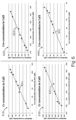
- Figure 5 shows a number of graphs comparing the actual concentrations of the calibration solutions (using HPLC, for example) with the concentrations calculated with the proposed method.
- Data points 511, 521, 531 and 541 are for calibration solutions stored at 10°C for 53 days.
- Data points 512, 522, 532 and 542 are for calibration solutions stored for 53 days at 10°C, 15 days at 32°C, and 34 days at 10°C.
- Data points 513, 523, 533 and 543 are for calibration solutions stored for 53 days at 10°C, 15 days at 6°C, 29 days at 10°C, and 20 days at 6°C.
- Data points 514, 524, 534 and 544 are for calibration solutions stored for 53 days at 10°C, 15 days at 25°C, 29 days at 10°C, and 20 days at 25°C.
- Data points 515, 525, 535 and 545 are for calibration solutions stored for 53 days at 10°C, 32 days at 32°C, 29 days at 10°C, and 20 days at 32°C.
- Graph 510 shows the calculated and actual Cr concentrations in the Cal2 solution at different temperature conditions.
- Graph 520 shows the calculated and actual Crn concentrations in the Cal2 solution at different temperature conditions.
- Graph 530 shows the calculated and actual Cr concentrations in the Cal3 solution at different temperature conditions.
- Graph 540 shows the calculated and actual Crn concentrations in the Cal3 solution at different temperature conditions.
- Figure 6 shows a number of graphs comparing the actual concentrations of the calibration solutions (using HPLC, for example) with the concentrations calculated with the example embodiment using a temperature logger to generate a temperature model.
- Graph 610 shows the calculated Cr concentrations in the Cal2 solution compared to the actual concentrations.
- Graph 620 shows the calculated Crn concentrations in the Cal2 solution compared to the actual concentrations.
- Graph 630 shows the calculated Cr concentrations in the Cal3 solution compared to the actual concentrations.
- Graph 640 shows the calculated Crn concentrations in the Cal3 solution compared to the actual concentrations.
Landscapes
- Health & Medical Sciences (AREA)
- Life Sciences & Earth Sciences (AREA)
- Chemical & Material Sciences (AREA)
- Hematology (AREA)
- Molecular Biology (AREA)
- Immunology (AREA)
- Engineering & Computer Science (AREA)
- Analytical Chemistry (AREA)
- Biochemistry (AREA)
- General Health & Medical Sciences (AREA)
- Physics & Mathematics (AREA)
- Pathology (AREA)
- General Physics & Mathematics (AREA)
- Organic Chemistry (AREA)
- Chemical Kinetics & Catalysis (AREA)
- Electrochemistry (AREA)
- Urology & Nephrology (AREA)
- Biomedical Technology (AREA)
- Microbiology (AREA)
- Biotechnology (AREA)
- Wood Science & Technology (AREA)
- Proteomics, Peptides & Aminoacids (AREA)
- Zoology (AREA)
- Cell Biology (AREA)
- Food Science & Technology (AREA)
- Medicinal Chemistry (AREA)
- Bioinformatics & Cheminformatics (AREA)
- General Engineering & Computer Science (AREA)
- Genetics & Genomics (AREA)
- Biophysics (AREA)
- Investigating Or Analysing Biological Materials (AREA)
- Measurement Of The Respiration, Hearing Ability, Form, And Blood Characteristics Of Living Organisms (AREA)
- Investigating Or Analyzing Materials Using Thermal Means (AREA)
Claims (9)
- Procédé d'étalonnage d'un dispositif permettant de mesurer la concentration de créatinine à l'aide d'une ou plusieurs solutions d'étalonnage, le procédé comprenant :la réception des concentrations à un temps initial de créatine, Cr, et/ou de créatinine, Crn, de la ou des solutions d'étalonnage ;la réception des résultats du dispositif de mesure au temps final ;le calcul de la concentration de Cr et/ou de Crn dans les solutions d'étalonnage à un temps final à l'aide d'un modèle de température, dans lequel le modèle de température indique les changements de température des solutions d'étalonnage du temps initial au temps final ; etla détermination d'une relation entre les résultats du dispositif de mesure et les concentrations calculées de Cr et/ou de Crn, dans lequel le dispositif de mesure comprend un capteur permettant de mesurer la créatine et/ou un capteur permettant de mesurer la créatinine dans une ou plusieurs des solutions d'étalonnage ;comprenant en outre la détermination du modèle de température en recevant des mesures des changements de température des solutions d'étalonnage à partir d'une sonde de température du temps initial au temps final ;dans lequel le temps final est supérieur à 14 jours après le temps initial.
- Procédé selon la revendication 1, dans lequel le dispositif de mesure comprend un capteur permettant de mesurer la créatine et la créatinine dans une ou plusieurs des solutions d'étalonnage.
- Procédé selon l'une quelconque revendication précédente, dans lequel le dispositif de mesure est un dispositif de mesure ampérométrique.
- Procédé selon la revendication 3, dans lequel lesdites mesures reçues sont des mesures enregistrées.
- Procédé selon l'une quelconque des revendications 3 à 4, dans lequel ladite détermination du modèle de température comprend l'étalonnage des mesures reçues des changements de température avec une seconde sonde de température.
- Procédé selon l'une quelconque revendication précédente, dans lequel la détermination d'une relation entre les résultats du dispositif de mesure et les concentrations calculées de Cr et Crn comprend le calcul des sensibilités des capteurs des dispositifs de mesure.
- Procédé selon la revendication 6, comprenant en outre la réception de mesures de température après le temps final et la mise à jour des sensibilités calculées des dispositifs de mesure à l'aide des mesures de température reçues après le temps final.
- Support lisible par ordinateur comprenant des instructions qui, lorsqu'elles sont exécutées par un ou plusieurs processeurs d'un dispositif électronique, poussent le dispositif électronique à utiliser le procédé selon l'une quelconque des revendications 1 à 7.
- Dispositif électronique comprenant :un ou plusieurs processeurs ; etune mémoire comprenant des instructions qui, lorsqu'elles sont exécutées par un ou plusieurs des processeurs poussent le dispositif électronique à utiliser le procédé selon l'une quelconque des revendications 1 à 7.
Priority Applications (1)
| Application Number | Priority Date | Filing Date | Title |
|---|---|---|---|
| EP25151490.7A EP4530635A3 (fr) | 2014-12-18 | 2015-12-17 | Nouveaux procédés d'étalonnage |
Applications Claiming Priority (2)
| Application Number | Priority Date | Filing Date | Title |
|---|---|---|---|
| DKPA201400737 | 2014-12-18 | ||
| PCT/EP2015/080131 WO2016097078A1 (fr) | 2014-12-18 | 2015-12-17 | Procédé d'étalonnage d'un dispositif de mesure de la concentration de créatinine |
Related Child Applications (1)
| Application Number | Title | Priority Date | Filing Date |
|---|---|---|---|
| EP25151490.7A Division EP4530635A3 (fr) | 2014-12-18 | 2015-12-17 | Nouveaux procédés d'étalonnage |
Publications (2)
| Publication Number | Publication Date |
|---|---|
| EP3234564A1 EP3234564A1 (fr) | 2017-10-25 |
| EP3234564B1 true EP3234564B1 (fr) | 2025-01-15 |
Family
ID=54850194
Family Applications (2)
| Application Number | Title | Priority Date | Filing Date |
|---|---|---|---|
| EP25151490.7A Pending EP4530635A3 (fr) | 2014-12-18 | 2015-12-17 | Nouveaux procédés d'étalonnage |
| EP15810663.3A Active EP3234564B1 (fr) | 2014-12-18 | 2015-12-17 | Methode de calibration d'appareil de mesure de la concentration de creatinine |
Family Applications Before (1)
| Application Number | Title | Priority Date | Filing Date |
|---|---|---|---|
| EP25151490.7A Pending EP4530635A3 (fr) | 2014-12-18 | 2015-12-17 | Nouveaux procédés d'étalonnage |
Country Status (6)
| Country | Link |
|---|---|
| US (3) | US20170363567A1 (fr) |
| EP (2) | EP4530635A3 (fr) |
| JP (3) | JP6435053B2 (fr) |
| CN (2) | CN107110815B (fr) |
| DK (1) | DK3234564T3 (fr) |
| WO (1) | WO2016097078A1 (fr) |
Families Citing this family (3)
| Publication number | Priority date | Publication date | Assignee | Title |
|---|---|---|---|---|
| DK3234563T3 (da) * | 2014-12-18 | 2025-02-10 | Radiometer Medical Aps | Fremgangsmåde til kalibrering af en indretning til måling af koncentrationen af kreatinin |
| US11327042B2 (en) * | 2019-04-05 | 2022-05-10 | Instrumentation Laboratory Company | Compositions and methods for improved creatinine measurement accuracy and uses thereof |
| WO2025128481A1 (fr) * | 2023-12-14 | 2025-06-19 | Siemens Healthcare Diagnostics Inc. | Correction de données d'étalonnage utilisées par des analyseurs de diagnostic sur la base de conditions de stockage de réactifs |
Citations (1)
| Publication number | Priority date | Publication date | Assignee | Title |
|---|---|---|---|---|
| US20040072277A1 (en) * | 2000-08-11 | 2004-04-15 | Bernhard Schaffar | Creatinine sensor calibration |
Family Cites Families (18)
| Publication number | Priority date | Publication date | Assignee | Title |
|---|---|---|---|---|
| JPS5758895A (en) * | 1980-09-24 | 1982-04-08 | Hitachi Ltd | Analytical method of creatinine and apparatus |
| CA2183573A1 (fr) | 1994-02-18 | 1995-08-24 | Gerald R. Magneson | Dispositif de calibrage/controle d'isoenzymes |
| US6136607A (en) | 1995-11-02 | 2000-10-24 | Bayer Corporation | Multi-analyte reference solutions with stable pO2 in zero headspace containers |
| JP3271741B2 (ja) * | 1996-06-04 | 2002-04-08 | 株式会社日立製作所 | 自動分析方法及び装置 |
| US6241863B1 (en) * | 1998-04-27 | 2001-06-05 | Harold G. Monbouquette | Amperometric biosensors based on redox enzymes |
| DE69914319T2 (de) * | 1998-05-13 | 2004-11-18 | Cygnus, Inc., Redwood City | Signalverarbeitung zur messung von physiologischen analyten |
| ES2633729T3 (es) * | 2001-08-22 | 2017-09-25 | Instrumentation Laboratory Company | Método para calibrar sensores electroquímicos |
| DK1692522T3 (da) | 2003-11-28 | 2012-04-02 | Radiometer Medical Aps | Referencevæske |
| US7275863B1 (en) * | 2003-12-04 | 2007-10-02 | Time Temperature Integration, Inc. | Threshold calorimeter/shelf life monitor |
| DE602005018081D1 (de) * | 2004-10-05 | 2010-01-14 | Siemens Healthcare Diagnostics | Stabiler kreatinin-biosensor mit drei enzymen |
| CA2699386C (fr) * | 2007-09-13 | 2016-08-09 | Abbott Point Of Care Inc. | Systeme d'assurance qualite ameliore et procede de test au point d'intervention |
| US20120181189A1 (en) * | 2009-09-24 | 2012-07-19 | Fresenius Medical Care Holdings, Inc. | Amperometric Creatinine Biosensor With Immobilized Enzyme-Polymer Composition And Systems Using Same, And Methods |
| WO2013003705A1 (fr) * | 2011-06-30 | 2013-01-03 | Abbott Point Of Care Inc. | Procédés et dispositifs pour déterminer les capacités d'utilisation d'un dispositif de détection |
| US20130000378A1 (en) * | 2011-06-30 | 2013-01-03 | Abbott Point Of Care Inc. | Methods and Devices for Sensing Device Signal Correction |
| US9224312B2 (en) * | 2011-06-30 | 2015-12-29 | Abbott Point Of Care Inc. | Methods and devices for determining sensing device usability |
| GB2512842A (en) * | 2013-04-08 | 2014-10-15 | Sphere Medical Ltd | Sensor calibration method and apparatus |
| WO2014182666A1 (fr) | 2013-05-06 | 2014-11-13 | Bio-Rad Laboratories, Inc. | Stabilisation d'analytes instables dans des matériaux de référence |
| DK3234563T3 (da) * | 2014-12-18 | 2025-02-10 | Radiometer Medical Aps | Fremgangsmåde til kalibrering af en indretning til måling af koncentrationen af kreatinin |
-
2015
- 2015-12-17 EP EP25151490.7A patent/EP4530635A3/fr active Pending
- 2015-12-17 DK DK15810663.3T patent/DK3234564T3/da active
- 2015-12-17 EP EP15810663.3A patent/EP3234564B1/fr active Active
- 2015-12-17 CN CN201580069428.4A patent/CN107110815B/zh active Active
- 2015-12-17 WO PCT/EP2015/080131 patent/WO2016097078A1/fr not_active Ceased
- 2015-12-17 US US15/536,309 patent/US20170363567A1/en not_active Abandoned
- 2015-12-17 JP JP2017532883A patent/JP6435053B2/ja active Active
- 2015-12-17 CN CN202111025880.4A patent/CN113866236A/zh active Pending
-
2018
- 2018-11-09 JP JP2018211046A patent/JP6866337B2/ja active Active
-
2021
- 2021-04-07 JP JP2021065083A patent/JP7183331B2/ja active Active
- 2021-10-25 US US17/509,485 patent/US11965854B2/en active Active
-
2024
- 2024-03-19 US US18/609,422 patent/US20240230578A1/en active Pending
Patent Citations (1)
| Publication number | Priority date | Publication date | Assignee | Title |
|---|---|---|---|---|
| US20040072277A1 (en) * | 2000-08-11 | 2004-04-15 | Bernhard Schaffar | Creatinine sensor calibration |
Also Published As
| Publication number | Publication date |
|---|---|
| JP7183331B2 (ja) | 2022-12-05 |
| JP2018500563A (ja) | 2018-01-11 |
| US20240230578A1 (en) | 2024-07-11 |
| WO2016097078A1 (fr) | 2016-06-23 |
| US20170363567A1 (en) | 2017-12-21 |
| DK3234564T3 (da) | 2025-02-10 |
| EP3234564A1 (fr) | 2017-10-25 |
| CN107110815A (zh) | 2017-08-29 |
| EP4530635A2 (fr) | 2025-04-02 |
| CN107110815B (zh) | 2021-09-21 |
| JP2019053079A (ja) | 2019-04-04 |
| CN113866236A (zh) | 2021-12-31 |
| JP6866337B2 (ja) | 2021-04-28 |
| US20220113274A1 (en) | 2022-04-14 |
| US11965854B2 (en) | 2024-04-23 |
| JP6435053B2 (ja) | 2018-12-05 |
| JP2021107823A (ja) | 2021-07-29 |
| EP4530635A3 (fr) | 2025-06-25 |
Similar Documents
| Publication | Publication Date | Title |
|---|---|---|
| US20240230578A1 (en) | Method for calibrating a device for measuring the concentration of creatinine | |
| EP3234563B1 (fr) | Methode de calibration d'appareil de mesure de la concentration de creatinine | |
| JP2511062B2 (ja) | ガス検定方法及び装置 | |
| EP2715369B1 (fr) | Étalonnage de biocapteur de glucose optique à l'aide de solutions d'étalonnage à différentes températures | |
| HK1248818A1 (zh) | 改进的生物传感器系统分析物测量 | |
| EP4530634A2 (fr) | Nouveaux procédés d'étalonnage | |
| JP7038230B2 (ja) | 細胞数を推定する方法および細胞数を推定する装置 | |
| DE60220288D1 (de) | Bestimmung der Genauigkeit eines Probevolumens in Biosensoren | |
| Gerken | Measurement of pH by NMR spectroscopy in concentrated aqueous fluoride buffers | |
| US20240125727A1 (en) | Electrochemical measurement with additional reference measurement | |
| US10969358B2 (en) | Method for correcting Crea sensor for calcium inhibition | |
| McGuigan et al. | Calculated and measured [Ca2+] in buffers used to calibrate Ca2+ macroelectrodes | |
| Tishchenko et al. | Application of potentiometric method using a cell without liquid junction to underway pH measurements in surface seawater | |
| Jalukse et al. | Estimation of uncertainty in electrochemical amperometric measurement of dissolved oxygen concentration | |
| CN107110813A (zh) | 对内源性调节剂进行校正的安培型肌酸酐传感器的校准概念 | |
| Ramamohan et al. | Modeling uncertainty due to instrument drift in clinical laboratories | |
| KR101079790B1 (ko) | 카이네틱 변화 정보를 이용한 측정목표물질의 특징값 추정방법 및 장치 | |
| Doinikov et al. | The pH scale for aqueous solutions as an international standard | |
| Opalski | Novel algorithms for ion activity estimation with on-line water monitoring application | |
| Blomqvist-Kutvonen et al. | Procedure 1 Measurement of ionized Mg2+ in human blood by ion-selective electrode in automatic blood electrolyte analyzer | |
| Gusakova et al. | Estimation of catecholamines in daily urine by stripping voltammetry |
Legal Events
| Date | Code | Title | Description |
|---|---|---|---|
| STAA | Information on the status of an ep patent application or granted ep patent |
Free format text: STATUS: THE INTERNATIONAL PUBLICATION HAS BEEN MADE |
|
| PUAI | Public reference made under article 153(3) epc to a published international application that has entered the european phase |
Free format text: ORIGINAL CODE: 0009012 |
|
| STAA | Information on the status of an ep patent application or granted ep patent |
Free format text: STATUS: REQUEST FOR EXAMINATION WAS MADE |
|
| 17P | Request for examination filed |
Effective date: 20170629 |
|
| AK | Designated contracting states |
Kind code of ref document: A1 Designated state(s): AL AT BE BG CH CY CZ DE DK EE ES FI FR GB GR HR HU IE IS IT LI LT LU LV MC MK MT NL NO PL PT RO RS SE SI SK SM TR |
|
| AX | Request for extension of the european patent |
Extension state: BA ME |
|
| DAV | Request for validation of the european patent (deleted) | ||
| DAX | Request for extension of the european patent (deleted) | ||
| STAA | Information on the status of an ep patent application or granted ep patent |
Free format text: STATUS: EXAMINATION IS IN PROGRESS |
|
| 17Q | First examination report despatched |
Effective date: 20180723 |
|
| TPAC | Observations filed by third parties |
Free format text: ORIGINAL CODE: EPIDOSNTIPA |
|
| P01 | Opt-out of the competence of the unified patent court (upc) registered |
Effective date: 20230530 |
|
| GRAP | Despatch of communication of intention to grant a patent |
Free format text: ORIGINAL CODE: EPIDOSNIGR1 |
|
| STAA | Information on the status of an ep patent application or granted ep patent |
Free format text: STATUS: GRANT OF PATENT IS INTENDED |
|
| RIC1 | Information provided on ipc code assigned before grant |
Ipc: G01N 33/70 20060101ALN20240220BHEP Ipc: G01N 27/327 20060101AFI20240220BHEP |
|
| INTG | Intention to grant announced |
Effective date: 20240305 |
|
| GRAJ | Information related to disapproval of communication of intention to grant by the applicant or resumption of examination proceedings by the epo deleted |
Free format text: ORIGINAL CODE: EPIDOSDIGR1 |
|
| STAA | Information on the status of an ep patent application or granted ep patent |
Free format text: STATUS: EXAMINATION IS IN PROGRESS |
|
| GRAP | Despatch of communication of intention to grant a patent |
Free format text: ORIGINAL CODE: EPIDOSNIGR1 |
|
| STAA | Information on the status of an ep patent application or granted ep patent |
Free format text: STATUS: GRANT OF PATENT IS INTENDED |
|
| INTC | Intention to grant announced (deleted) | ||
| RIC1 | Information provided on ipc code assigned before grant |
Ipc: G01N 33/70 20060101ALN20240711BHEP Ipc: G01N 27/327 20060101AFI20240711BHEP |
|
| INTG | Intention to grant announced |
Effective date: 20240807 |
|
| GRAS | Grant fee paid |
Free format text: ORIGINAL CODE: EPIDOSNIGR3 |
|
| GRAA | (expected) grant |
Free format text: ORIGINAL CODE: 0009210 |
|
| STAA | Information on the status of an ep patent application or granted ep patent |
Free format text: STATUS: THE PATENT HAS BEEN GRANTED |
|
| AK | Designated contracting states |
Kind code of ref document: B1 Designated state(s): AL AT BE BG CH CY CZ DE DK EE ES FI FR GB GR HR HU IE IS IT LI LT LU LV MC MK MT NL NO PL PT RO RS SE SI SK SM TR |
|
| REG | Reference to a national code |
Ref country code: CH Ref legal event code: EP Ref country code: GB Ref legal event code: FG4D |
|
| REG | Reference to a national code |
Ref country code: DE Ref legal event code: R096 Ref document number: 602015090864 Country of ref document: DE |
|
| REG | Reference to a national code |
Ref country code: DK Ref legal event code: T3 Effective date: 20250206 |
|
| REG | Reference to a national code |
Ref country code: IE Ref legal event code: FG4D |
|
| REG | Reference to a national code |
Ref country code: NL Ref legal event code: MP Effective date: 20250115 |
|
| PG25 | Lapsed in a contracting state [announced via postgrant information from national office to epo] |
Ref country code: NL Free format text: LAPSE BECAUSE OF FAILURE TO SUBMIT A TRANSLATION OF THE DESCRIPTION OR TO PAY THE FEE WITHIN THE PRESCRIBED TIME-LIMIT Effective date: 20250115 |
|
| PG25 | Lapsed in a contracting state [announced via postgrant information from national office to epo] |
Ref country code: RS Free format text: LAPSE BECAUSE OF FAILURE TO SUBMIT A TRANSLATION OF THE DESCRIPTION OR TO PAY THE FEE WITHIN THE PRESCRIBED TIME-LIMIT Effective date: 20250415 |
|
| PG25 | Lapsed in a contracting state [announced via postgrant information from national office to epo] |
Ref country code: FI Free format text: LAPSE BECAUSE OF FAILURE TO SUBMIT A TRANSLATION OF THE DESCRIPTION OR TO PAY THE FEE WITHIN THE PRESCRIBED TIME-LIMIT Effective date: 20250115 |
|
| PG25 | Lapsed in a contracting state [announced via postgrant information from national office to epo] |
Ref country code: PL Free format text: LAPSE BECAUSE OF FAILURE TO SUBMIT A TRANSLATION OF THE DESCRIPTION OR TO PAY THE FEE WITHIN THE PRESCRIBED TIME-LIMIT Effective date: 20250115 |
|
| PG25 | Lapsed in a contracting state [announced via postgrant information from national office to epo] |
Ref country code: ES Free format text: LAPSE BECAUSE OF FAILURE TO SUBMIT A TRANSLATION OF THE DESCRIPTION OR TO PAY THE FEE WITHIN THE PRESCRIBED TIME-LIMIT Effective date: 20250115 |
|
| REG | Reference to a national code |
Ref country code: LT Ref legal event code: MG9D |
|
| PG25 | Lapsed in a contracting state [announced via postgrant information from national office to epo] |
Ref country code: NO Free format text: LAPSE BECAUSE OF FAILURE TO SUBMIT A TRANSLATION OF THE DESCRIPTION OR TO PAY THE FEE WITHIN THE PRESCRIBED TIME-LIMIT Effective date: 20250415 Ref country code: IS Free format text: LAPSE BECAUSE OF FAILURE TO SUBMIT A TRANSLATION OF THE DESCRIPTION OR TO PAY THE FEE WITHIN THE PRESCRIBED TIME-LIMIT Effective date: 20250515 |
|
| REG | Reference to a national code |
Ref country code: AT Ref legal event code: MK05 Ref document number: 1760136 Country of ref document: AT Kind code of ref document: T Effective date: 20250115 |
|
| PG25 | Lapsed in a contracting state [announced via postgrant information from national office to epo] |
Ref country code: HR Free format text: LAPSE BECAUSE OF FAILURE TO SUBMIT A TRANSLATION OF THE DESCRIPTION OR TO PAY THE FEE WITHIN THE PRESCRIBED TIME-LIMIT Effective date: 20250115 |
|
| PG25 | Lapsed in a contracting state [announced via postgrant information from national office to epo] |
Ref country code: PT Free format text: LAPSE BECAUSE OF FAILURE TO SUBMIT A TRANSLATION OF THE DESCRIPTION OR TO PAY THE FEE WITHIN THE PRESCRIBED TIME-LIMIT Effective date: 20250515 Ref country code: LV Free format text: LAPSE BECAUSE OF FAILURE TO SUBMIT A TRANSLATION OF THE DESCRIPTION OR TO PAY THE FEE WITHIN THE PRESCRIBED TIME-LIMIT Effective date: 20250115 |
|
| PG25 | Lapsed in a contracting state [announced via postgrant information from national office to epo] |
Ref country code: BG Free format text: LAPSE BECAUSE OF FAILURE TO SUBMIT A TRANSLATION OF THE DESCRIPTION OR TO PAY THE FEE WITHIN THE PRESCRIBED TIME-LIMIT Effective date: 20250115 Ref country code: GR Free format text: LAPSE BECAUSE OF FAILURE TO SUBMIT A TRANSLATION OF THE DESCRIPTION OR TO PAY THE FEE WITHIN THE PRESCRIBED TIME-LIMIT Effective date: 20250416 |
|
| PG25 | Lapsed in a contracting state [announced via postgrant information from national office to epo] |
Ref country code: AT Free format text: LAPSE BECAUSE OF FAILURE TO SUBMIT A TRANSLATION OF THE DESCRIPTION OR TO PAY THE FEE WITHIN THE PRESCRIBED TIME-LIMIT Effective date: 20250115 |
|
| PG25 | Lapsed in a contracting state [announced via postgrant information from national office to epo] |
Ref country code: SE Free format text: LAPSE BECAUSE OF FAILURE TO SUBMIT A TRANSLATION OF THE DESCRIPTION OR TO PAY THE FEE WITHIN THE PRESCRIBED TIME-LIMIT Effective date: 20250115 |
|
| PG25 | Lapsed in a contracting state [announced via postgrant information from national office to epo] |
Ref country code: SM Free format text: LAPSE BECAUSE OF FAILURE TO SUBMIT A TRANSLATION OF THE DESCRIPTION OR TO PAY THE FEE WITHIN THE PRESCRIBED TIME-LIMIT Effective date: 20250115 |
|
| PG25 | Lapsed in a contracting state [announced via postgrant information from national office to epo] |
Ref country code: IT Free format text: LAPSE BECAUSE OF FAILURE TO SUBMIT A TRANSLATION OF THE DESCRIPTION OR TO PAY THE FEE WITHIN THE PRESCRIBED TIME-LIMIT Effective date: 20250115 |
|
| REG | Reference to a national code |
Ref country code: DE Ref legal event code: R097 Ref document number: 602015090864 Country of ref document: DE |
|
| PG25 | Lapsed in a contracting state [announced via postgrant information from national office to epo] |
Ref country code: EE Free format text: LAPSE BECAUSE OF FAILURE TO SUBMIT A TRANSLATION OF THE DESCRIPTION OR TO PAY THE FEE WITHIN THE PRESCRIBED TIME-LIMIT Effective date: 20250115 Ref country code: CZ Free format text: LAPSE BECAUSE OF FAILURE TO SUBMIT A TRANSLATION OF THE DESCRIPTION OR TO PAY THE FEE WITHIN THE PRESCRIBED TIME-LIMIT Effective date: 20250115 |
|
| PG25 | Lapsed in a contracting state [announced via postgrant information from national office to epo] |
Ref country code: RO Free format text: LAPSE BECAUSE OF FAILURE TO SUBMIT A TRANSLATION OF THE DESCRIPTION OR TO PAY THE FEE WITHIN THE PRESCRIBED TIME-LIMIT Effective date: 20250115 |
|
| PG25 | Lapsed in a contracting state [announced via postgrant information from national office to epo] |
Ref country code: SK Free format text: LAPSE BECAUSE OF FAILURE TO SUBMIT A TRANSLATION OF THE DESCRIPTION OR TO PAY THE FEE WITHIN THE PRESCRIBED TIME-LIMIT Effective date: 20250115 |
|
| PLBE | No opposition filed within time limit |
Free format text: ORIGINAL CODE: 0009261 |
|
| STAA | Information on the status of an ep patent application or granted ep patent |
Free format text: STATUS: NO OPPOSITION FILED WITHIN TIME LIMIT |
|
| REG | Reference to a national code |
Ref country code: CH Ref legal event code: L10 Free format text: ST27 STATUS EVENT CODE: U-0-0-L10-L00 (AS PROVIDED BY THE NATIONAL OFFICE) Effective date: 20251126 |
|
| 26N | No opposition filed |
Effective date: 20251016 |
|
| REG | Reference to a national code |
Ref country code: CH Ref legal event code: U11 Free format text: ST27 STATUS EVENT CODE: U-0-0-U10-U11 (AS PROVIDED BY THE NATIONAL OFFICE) Effective date: 20260101 |
|
| PGFP | Annual fee paid to national office [announced via postgrant information from national office to epo] |
Ref country code: GB Payment date: 20251223 Year of fee payment: 11 |
|
| PGFP | Annual fee paid to national office [announced via postgrant information from national office to epo] |
Ref country code: DK Payment date: 20251222 Year of fee payment: 11 |
|
| PGFP | Annual fee paid to national office [announced via postgrant information from national office to epo] |
Ref country code: FR Payment date: 20251230 Year of fee payment: 11 |
|
| PGFP | Annual fee paid to national office [announced via postgrant information from national office to epo] |
Ref country code: DE Payment date: 20251229 Year of fee payment: 11 |
|
| PGFP | Annual fee paid to national office [announced via postgrant information from national office to epo] |
Ref country code: CH Payment date: 20260101 Year of fee payment: 11 |