EP3235582B1 - Schneideinsatz, schneidwerkzeug sowie verfahren zur herstellung des schneidartikels - Google Patents
Schneideinsatz, schneidwerkzeug sowie verfahren zur herstellung des schneidartikels Download PDFInfo
- Publication number
- EP3235582B1 EP3235582B1 EP15870031.0A EP15870031A EP3235582B1 EP 3235582 B1 EP3235582 B1 EP 3235582B1 EP 15870031 A EP15870031 A EP 15870031A EP 3235582 B1 EP3235582 B1 EP 3235582B1
- Authority
- EP
- European Patent Office
- Prior art keywords
- cutting
- cutting edge
- insert
- body member
- holder
- Prior art date
- Legal status (The legal status is an assumption and is not a legal conclusion. Google has not performed a legal analysis and makes no representation as to the accuracy of the status listed.)
- Active
Links
Images


Classifications
-
- B—PERFORMING OPERATIONS; TRANSPORTING
- B23—MACHINE TOOLS; METAL-WORKING NOT OTHERWISE PROVIDED FOR
- B23C—MILLING
- B23C5/00—Milling-cutters
- B23C5/16—Milling-cutters characterised by physical features other than shape
- B23C5/20—Milling-cutters characterised by physical features other than shape with removable cutter bits or teeth or cutting inserts
- B23C5/202—Plate-like cutting inserts with special form
-
- B—PERFORMING OPERATIONS; TRANSPORTING
- B23—MACHINE TOOLS; METAL-WORKING NOT OTHERWISE PROVIDED FOR
- B23C—MILLING
- B23C5/00—Milling-cutters
- B23C5/16—Milling-cutters characterised by physical features other than shape
- B23C5/20—Milling-cutters characterised by physical features other than shape with removable cutter bits or teeth or cutting inserts
- B23C5/22—Securing arrangements for bits or teeth or cutting inserts
- B23C5/2204—Securing arrangements for bits or teeth or cutting inserts with cutting inserts clamped against the walls of the recess in the cutter body by a clamping member acting upon the wall of a hole in the insert
- B23C5/2208—Securing arrangements for bits or teeth or cutting inserts with cutting inserts clamped against the walls of the recess in the cutter body by a clamping member acting upon the wall of a hole in the insert for plate-like cutting inserts
-
- B—PERFORMING OPERATIONS; TRANSPORTING
- B23—MACHINE TOOLS; METAL-WORKING NOT OTHERWISE PROVIDED FOR
- B23C—MILLING
- B23C2200/00—Details of milling cutting inserts
- B23C2200/04—Overall shape
- B23C2200/0433—Parallelogram
-
- B—PERFORMING OPERATIONS; TRANSPORTING
- B23—MACHINE TOOLS; METAL-WORKING NOT OTHERWISE PROVIDED FOR
- B23C—MILLING
- B23C2200/00—Details of milling cutting inserts
- B23C2200/20—Top or side views of the cutting edge
- B23C2200/208—Wiper, i.e. an auxiliary cutting edge to improve surface finish
-
- B—PERFORMING OPERATIONS; TRANSPORTING
- B23—MACHINE TOOLS; METAL-WORKING NOT OTHERWISE PROVIDED FOR
- B23C—MILLING
- B23C2200/00—Details of milling cutting inserts
- B23C2200/36—Other features of the milling insert not covered by B23C2200/04 - B23C2200/32
- B23C2200/367—Mounted tangentially, i.e. where the rake face is not the face with largest area
-
- B—PERFORMING OPERATIONS; TRANSPORTING
- B23—MACHINE TOOLS; METAL-WORKING NOT OTHERWISE PROVIDED FOR
- B23C—MILLING
- B23C2226/00—Materials of tools or workpieces not comprising a metal
- B23C2226/31—Diamond
-
- B—PERFORMING OPERATIONS; TRANSPORTING
- B23—MACHINE TOOLS; METAL-WORKING NOT OTHERWISE PROVIDED FOR
- B23C—MILLING
- B23C2226/00—Materials of tools or workpieces not comprising a metal
- B23C2226/31—Diamond
- B23C2226/315—Diamond polycrystalline [PCD]
-
- B—PERFORMING OPERATIONS; TRANSPORTING
- B23—MACHINE TOOLS; METAL-WORKING NOT OTHERWISE PROVIDED FOR
- B23C—MILLING
- B23C5/00—Milling-cutters
- B23C5/02—Milling-cutters characterised by the shape of the cutter
- B23C5/06—Face-milling cutters, i.e. having only or primarily a substantially flat cutting surface
Definitions
- the present embodiments relate to a cutting insert, a cutting tool, and a method of manufacturing a machined product.
- Patent Document 1 As a cutting insert used when a workpiece, such as metal, is subjected to a milling process, an indexable insert in accordance with the preamble of claim 1 is described in Japanese Unexamined Patent Publication No. 2003-231015 (Patent Document 1).
- the indexable insert described in Patent Document 1 is made up of an indexable insert body (body member) composed of a sintered body, such as cemented carbide or ceramics, and a diamond insert (cutting edge member).
- a recessed part is disposed at an intersecting portion of a side flank surface and a front flank surface on a rake surface of the indexable insert body, and an insert is brazed to the recessed part.
- the diamond insert is provided with an outer side cutting edge and a bottom cutting edge, namely, the outer side cutting edge and the bottom cutting edge are made of diamond, thereby enhancing the strength of a cutting edge.
- a through hole extends from a rake surface located at the front in a rotation direction to a surface located at the rear in the rotation direction in the indexable insert.
- the indexable insert is configured to be attached to a rotary cutting tool body (holder) by inserting a clamp screw member into the through hole.
- US 4,728,228 A describes a milling cutter having a cutter body including one or more steps extending along the outer peripheral edge of the cutter body, wherein cartridges are detachably mounted on the step, and wherein each of the cartridges have a plurality of equally spaced cutting edges.
- the cutter body has a radially outer step and a radially inner step close thereto, and the cartridges with roughly cutting edges are mounted on the radially outer step.
- JP 2002 254213 describes a tip and cutting tools including the same
- JP H10 180507 A describes a cutting blade member
- US 2008/145166 A1 describes a mechanical engraver including a rotating plate, a first cutting tool, and a second cutting tool
- DE 10 2005 031988 A1 describes a cutting tool having an annular cutter carrier.
- the present embodiments are intended to provide a cutting insert having good durability when the cutting insert is made up of a body member and a cutting edge member.
- the invention provides a cutting insert according to claim 1, a cutting tool according to claim 4, and a method of manufacturing a machined product according to claim 7. Preferred embodiments are provided in the dependent claims.
- a cutting insert and a cutting tool according to an embodiment are described in detail below with reference to the drawings.
- the drawings referred to in the following show, in simplified form, only major components among components of the embodiments. Therefore, the cutting insert and the cutting tool of the present invention may include any optional component not shown in the drawings referred to in the present description. Sizes of the components in the drawings are not faithful to sizes of actual components and to size ratios of these individual components.
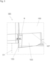
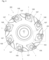
- the cutting tool 101 of the present embodiment includes a holder 103, a plurality of cutting inserts 1 (hereinafter also referred to as "inserts 1"), and a screw 105.
- the holder 103 has a rotation axis O1.
- a side where the inserts 1 are located is referred to as a front end side, and the opposite of the front end side is referred to as a rear end side, the holder 103 is a columnar body member extending along the rotation axis O1 from the front end side toward the rear end side.
- the holder 103 rotates in a rotation direction X1 around the rotation axis O1 about the rotation axis O1 during a cutting process of a workpiece for manufacturing a machined product.
- a central axis of the holder 103 that is the columnar body and the rotation axis O1 of the holder 103 coincide with each other.
- a side close to the rotation axis O1 is referred to as an inner peripheral side
- a side away from the rotation axis O1 is referred to as an outer peripheral side.
- a direction from the rear end side of the holder 103 toward the front end side thereof is referred to as a front end direction
- a direction from the front end side of the holder 103 to the rear end side thereof is referred to as a rear end direction.
- the size of the holder 103 is suitably settable according to the size of a workpiece. For example, a length in the direction along the rotation axis O1 is settable to approximately 30-90 mm. A width (diameter) in a direction orthogonal to the rotation axis O1 is settable to approximately 20-500 mm.
- a plurality of insert pockets 107 are located along an outer peripheral side on the front end side of the holder 103.
- the pockets 107 may be disposed at equal intervals or unequal intervals so as to have rotational symmetry around the rotation axis O1.
- the pockets 107 are preferably disposed at equal intervals in order to reduce variations in load applied to the inserts 1 attached to the pockets 107.
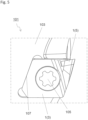
- the pockets 107 are located on the holder 103, and therefore the holder 103 is not a strict columnar body. Each of the inserts 1 attached to the pockets 107 is fixed to the holder 103 by the screw 105.
- exemplary eight pockets 107 are disposed on the holder 103 and the inserts 1 are respectively located at these eight pockets 107.
- the number of the pockets 107, and the number of the inserts 1 attached to the holder 103 are not limited to eight. Therefore, both numbers may be, for example, two, three, four, five, six, or ten or more.
- each of the inserts 1 is made up of the body member 3 and the cutting member 5, and has a columnar body as a whole.
- the body member 3 is a columnar body, and the body member 3 is a quadrangular columnar body.
- the body member 3 includes an upper surface 7, a lower surface 9, and an outer side surface 11. The outer side surface 11 is located between the upper surface 7 and the lower surface 9.
- the cutting member 5 is located at a corner part of the outer side surface 11 of the body member 3. In other words, the cutting member 5 is located at a recessed part 13 included in the corner part of the outer side surface 11 of the body member 3.
- each of the inserts 1 are therefore the columnar body as a whole.
- the cutting member 5 is fixed to the body member 3.
- the cutting member 5 is connected to the body member 3 by using a brazing filler metal or the like in the present embodiment.
- hatching made up of diagonal lines is applied to the cutting member 5 in FIGs. 6 to 10 .
- the cutting member 5 is a part of the insert 1 and includes a cutting edge 15 for cutting a workpiece. Also, the cutting member 5 has high hardness to ensure the high strength cutting edge 15 in the insert 1. Thus, the cutting edge 15 is not located on the body member 3 but located on the cutting member 5 in the present embodiment.
- the body member 3 is a base part in the insert 1 and need not have hardness equal to or higher than that of the cutting member 3. Manufacturing costs for the inserts 1 are reducible while enhancing the strength of the cutting edges 15 because the inserts 1 are thus respectively made up of the body member 3 and the cutting member 5.
- cemented carbide or cermet is usable as a material of a member constituting the body member 3.
- compositions of the cemented carbide include WC-Co, WC-TiC-Co, and WC-TiC-TaC-Co.
- WC-Co is producible by adding cobalt (Co) powder to tungsten carbide (WC), followed by sintering.
- Co cobalt
- TiC titanium carbide
- TaC tantalum carbide
- TiC-TiC-Co tantalum carbide
- the cermet is a sintered composite material obtainable by compositing the metal with a ceramic ingredient.
- Specific examples of the cermet include those containing a titanium compound as a main component such as titanium carbide (TiC) or titanium nitride (TiN).
- the cutting member 5 is made of a material having a higher hardness than a material constituting the body member 3. Specifically, examples of the material of the cutting member 5 include polycrystalline diamond and monocrystalline diamond. The hardness of the body member 3 and the cutting member 5 is evaluable by measuring Vickers hardness of their respective parts.
- a well-known test method can be used.
- a pyramid-shaped indenter made of a square pyramid diamond is pressed against the surface of a material, and then measured is an indent that remains after removing a load.
- an indent is formed on the body member 3 because the material of the body member 3 is made of the material having a lower hardness than the indenter as illustrated above.
- the material of the cutting member 5 is monocrystalline diamond, little or no indent is formed.
- the upper surface 7 and the lower surface 9 of the body member 3 have a tetragonal shape.
- the upper surface 7 is a surface that comes into contact with a seating surface of the pocket 107 of the holder 103 when the insert 1 is attached to the holder 103.
- the lower surface 9 is a surface being exposed to the front end side of the holder 103 when the insert 1 is attached to the holder 103.
- the outer side surface 11 of the body member 3 includes four surface regions of a front side surface 17, a rear side surface 19, an outer side surface 21, and an inner side surface 23.
- the side surfaces 17, 19, 21 and 23 are respectively correspond to sides of the upper surface 7 and the lower surface 9 each having the tetragonal shape (where the side surfaces are named not only from FIG. 6 but also from a positional relationship under a situation of the base member 3 attached to the holder 103).
- These surface regions have an approximately tetragonal shape in their respective front views.
- the front side surface 17 is a surface region located at the front in the rotation direction X1 when the insert 1 is attached to the holder 103. In the front view of the front side surface 17, its width in a direction orthogonal to the rotation axis O1 is larger than its height in a direction along the rotation axis O1.
- the rear side surface 19 is another surface region located at the rear in the rotation direction X1 when the insert 1 is attached to the holder 103. The rear side surface 19 is located opposite to the front side surface 17, and comes into contact with the pocket 107 when the insert 1 is attached to the holder 103.
- the outer side surface 21 is another surface region of the outer side surface 1 which is located closest to the outer peripheral side when the insert 1 is attached to the holder 103.
- the outer side surface 21 protrudes from the holder 103 in an outer side direction.
- the entirety of the outer side surface 21 protrudes from the holder 103 in the present embodiment, there is no intention to limit to this configuration.
- a part of the outer side surface 21 which is close to the front side surface 17 may partially protrude from the holder 103 in the outer side direction.
- the inner side surface 23 is another surface region located close to the inner peripheral side when the insert 1 is attached to the holder 103, and comes into contact with the pocket 107 when the insert 1 is attached to the holder 103.
- the description that the upper surface 7, the lower surface 9, the front side surface 17, the rear side surface 19, the outer side surface 21, and the inner side surface 23 have the tetragonal shape denotes that these surfaces need to have an approximately tetragonal shape but need not to have a strict tetragonal shape. Corners of the surface regions may have a round shape in their respective front views. Also, sides located so as to connect adjacent corners need not to have a strict straight line, but may be partially made into a shape having concave and convex.
- the size of the body member 3 is not particularly limited.
- a maximum value of a width between the front side surface 17 and the rear side surface 19 can be set to approximately 5-20 mm in a top view (in a front view of the upper surface 3).
- a maximum value of a width between the inner side surface 23 and the outer side surface 21 can be set to approximately 5-20 mm in the top view.
- a maximum value of a thickness between the upper surface 7 and the lower surface 9 is 3-10 mm.
- the body member 3 includes the recessed part 13.
- the recessed part 13 is located at a part thereof which corresponds to a region of the front side surface 17 on the outer side surface 11 which is close to the outer side surface 21, corresponds to a region of the outer side surface 21 which is close to the front side surface 17, and corresponds to a corner of the lower surface 9. It can also be said that the recessed part 13 in the present embodiment is located at a part of a corner of the upper surface 7 and a part of the corner of the lower surface 9, besides on the outer side surface 11.
- the cutting member 5 is located at the recessed part 13 of the body member 3.
- the cutting members includes at least three surfaces that are exposed.
- the cutting member 5 has a tetragonal plate shape, and includes a first surface 25 located close to the front side surface 17 of the body member 3 that is exposed.
- the cutting member 5 also include a second surface 27 located close to the outer side surface 21 of the body member 3, and a third surface 29 located close to the lower surface 9 of the body member 3 that are exposed.
- the cutting member 5 includes the cutting edge 15 on an intersecting portion where two of the exposed surfaces intersect each other.
- the cutting edge 15 includes a first cutting edge 15A and a second cutting edge 15B in the present embodiment.
- the first cutting edge 15A is located at an intersecting portion of the cutting member 5 where the first surface 25 and the second surface 27 intersect each other. Accordingly, the first cutting edge 15A extends in a direction from the upper surface 7 toward the lower surface 9 of the body member 3 in the present embodiment.
- the cutting tool 101 is a tool for use in a so-called milling process for cutting a workpiece by causing the holder 103 to move in the direction approximately orthogonal to the rotation axis O1 while the holder 103 is rotating around the rotation axis O1.
- the first cutting edge 15A therefore functions as a so-called outer side cutting edge configured to mainly cut the workpiece.
- the first cutting edge 15A is located over the entirety of the intersecting portion of the first surface 25 and the second surface 27 in the present embodiment. Although the first cutting edge 15A may be located at least on a part of the intersecting portion of the first surface 25 and the second surface 27. The first cutting edge 15A is disposed over the entirety of the intersecting portion of the first surface 25 and the second surface 27 in order to ensure a large height of cut in the present embodiment.
- the length of the first cutting edge 15A can be set to, for example, approximately 3-7 mm.
- the first cutting edge 15A protrudes outward from the outer side surface 11 of the holder 103 when the insert 1 is attached to the holder 103.
- the first cutting edge 15A has such a straight line form that is inclined so as to approach the rear side surface 19 as going from an end portion of the first cutting edge 15A which is close to the lower surface 9 toward an end portion of the first cutting edge 15A which is close to the upper surface 7.
- An axial rake ⁇ of the first cutting edge 15A can be set to, for example, approximately 3-10° when the insert 1 is attached to the holder 103, a.
- the second cutting edge 15B is located on an intersecting portion of the first surface 25 and the third surface 29 in the cutting member 5. Therefore, the second cutting edge 15B in the present embodiment extends in a direction along the lower surface 9 of the body member 3.
- the second cutting edge 15B functions as a "flat cutting edge" to decrease unevenness on a machined surface of the workpiece.
- the second cutting edge 15B need not necessarily be disposed over the entirety of the intersecting portion of the first surface 25 and the third surface 29, but is preferably disposed so as to include a part of the second cutting edge 15B which is located close to the outer periphery in a state of being attached to the holder 103 (which is namely a right side of the second cutting edge 15B in FIG. 9 ).
- the length of the second cutting edge 15B can be set to, for example, approximately 2-5 mm.
- the second cutting edge 15B protrudes toward the front end side of the holder 103 when the insert 1 is attached to the holder 103.
- the second cutting edge 15B has a downwardly convex shape when viewed from the front in the rotation direction X1 (for example, in FIG. 9 ). When the second cutting edge 15B is so located, it is possible to minimize the likelihood that the body member 3 can come into contact with the workpiece during the cutting process of the workpiece.
- the second cutting edge 15B includes a straight line portion.
- the straight line portion extends from the outer peripheral side in the state of being attached to the holder 103 (i.e., the right side of the second cutting edge 15B in FIG. 9 ) toward an inner peripheral side.
- the second cutting edge 15B can function well as the flat cutting edge.
- a radial rake of the second cutting edge 15B can be set to, for example, approximately 5-20° when the insert 1 is attached to the holder 103.
- the body member 3 of the insert 1 includes a through hole 31 .
- the through hole 31 is a portion through which the insert 1 is screwed to the holder 103.
- the screw 105 is inserted into the through hole 31 of the insert 1, a front end of the screw 105 is inserted into a screw hole (not shown) that is formed in the pocket 107 and therefore the screw 105 is fixed to the screw hole. Accordingly, the insert 1 is attached to the holder 103.
- the through hole 31 penetrates through the upper surface 7 and the lower surface 9 of the main body 3.
- the through hole 31 is located from the upper surface 7 to the lower surface 9 of the body member 3, and opens into the upper surface 7 and the lower surface 9. Therefore, the through hole 31 does not open into the outer side surface 11 of the main body 3.
- a penetrating direction of the through hole 31 extends along the rotation axis O1.
- a small thickness region is formed between the recessed part 13 and the through hole 31 of the body member 3. If the small thickness region exists, the small thickness region can be damaged due to a load applied to the insert 1 during the cutting process.
- the through hole 31 penetrates through the lower surface 9 and the upper surface 7, the recessed part 13 and the through hole 31 are located away from each other. In other words, the first cutting edge 15A subjected to a large cutting resistance and the through hole 31 are located away from each other. Therefore, a formation of the small thickness region between the recessed part 13 and the through hole 31 can be avoided. This leads to the insert 1 having good durability.
- the through hole 31 is formed from the front side surface 17 to the rear side surface 19, it follows that the head of the screw 105 is located ahead of a chip flow, and hence the head of the screw 105 can be damaged.
- the through hole 31 opens into the upper surface 7 and the lower surface 9 in the present embodiment, and therefore, the likelihood of damage to the head of the screw 105 can be reduced.
- the first surface 25 of the cutting member 5 is located at the front in the rotation direction X1 . Therefore, the first surface 25 in the cutting member 5 functions as "a rake surface” along which chips flow during the cutting process. Hereinafter, the first surface 25 is therefore also referred to as the rake surface.
- the second surface 27 and the third surface 29 in the cutting member 5 function as "a flank surface" during the cutting process.
- the entirety of the second cutting edge 15B is located closer to the outer peripheral side than the through hole 31. Specifically, the entirety of the second cutting edge 15B is located closer to the outer peripheral side than a middle part of the through hole 31 whose inner diameter is constant. A load due to a principal force is applied from the second cutting edge 15B toward the rear in the rotation direction X1 during the cutting process.
- the second cutting edge 15B is located closer to the outer peripheral side than the through hole 31, direct transmit of the load from the second cutting edge 15B toward the through hole 31 can be avoided. As a result, the durability of the insert 1 is further enhanced.
- the phrase "being located closer to the outer peripheral side" denotes being located away from the rotation axis O1 of the holder 103.
- a vertical thickness of the body member 3 in the corner part where the cutting member 5 is located is larger than a vertical thickness thereof in a part other than the corner part.
- a part of the body member 3 which is located on the outer peripheral side protrudes toward the front end side.
- the inner peripheral side of the body member 3 has a partially indented shape in FIG. 9 .
- a ridge line where the outer side surface 21 and the lower surface 9 intersect each other is inclined so as to be located closer to the front end side as going toward the front in the rotation direction X1, and he second cutting edge 15B protrudes most toward the front end direction, when the insert 1 is viewed from the side as shown in FIG. 10 . This makes it possible to reduce the likelihood that the lower surface 9 comes into contact with the workpiece.
- the insert 1 has a parallelogram shape in which an angle formed by the front side surface 17 and the outer side surface 21 is an acute angle when the insert 1 is viewed from above. This ensures a large distance between the first cutting edge 15A and the through hole 31, thereby making it easier to ensure a large thickness between a concave shaped portion to which the cutting member 5 in the body member 3 is connected, and the through hole 31. It is therefore possible to further enhance the durability of the insert 1.
- the entirety of the cutting edge 15 is located at the front in the rotation direction relative to the through hole 31.
- a load is also applied from the cutting edge 15 toward the rotation axis O1 during the cutting process.
- the entirety of the cutting edge 15 is located at the front in the rotation direction relative to the through hole 31, it is possible to avoid that the load is directly transmitted from the cutting edge 15 toward the through hole 31. Consequently, the insert 1 can have enhanced durability.
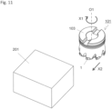
- the machined product is manufacturable by subjecting a workpiece 201 to a cutting process.
- the method of manufacturing the machined product in the present embodiment includes the following steps:
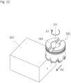
- the cutting tool 101 is relatively brought near the workpiece 201 by rotating the cutting tool 101 around the rotation axis O1 and moving the cutting tool 101 in X2 direction as shown in FIG. 11 .
- the workpiece 201 is cut by bringing the cutting edge 15 in the cutting tool 101 into contact with the workpiece 201.
- the cutting edge 15 As the cutting edge 15, the first cutting edge and the second cutting edge are brought into contact with the workpiece 201 in the present embodiment as shown in FIG. 12 .
- the cutting tool 101 is relatively separated from the workpiece 201 by further moving the cutting tool 101 in the X2 direction as shown in FIG. 13 .
- the cutting tool 101 is brought near the workpiece 201 in a state in which the workpiece 201 is fixed and the cutting tool 101 is rotated around the rotation axis O1.
- the workpiece 201 is cut by bringing the first cutting edge and the second cutting edge of the insert 1 being rotated into contact with the workpiece 201.
- the cutting tool 101 being rotated is separated from the workpiece 201.
- the cutting tool 101 is brought into contact with the workpiece 201, or the cutting tool 101 is separated from the workpiece 201 by moving the cutting tool 101 in each of the above steps. Nevertheless, there is no intention to limit to such embodiments.
- the workpiece 201 may be brought near the cutting tool 101.
- the workpiece 201 may be separated from the cutting tool 101.
- Representative examples of the material of the workpiece 201 include aluminum, carbon steel, alloy steel, stainless steel, cast iron, and nonferrous metals.
Landscapes
- Engineering & Computer Science (AREA)
- Mechanical Engineering (AREA)
- Milling Processes (AREA)
- Cutting Tools, Boring Holders, And Turrets (AREA)
Claims (7)
- Schneideinsatz (1), aufweisend ein Schneidelement (5), das an einem Körperelement (3) befestigt ist,wobei das Körperelement (3) eine Säulenform hat und aufweist:eine obere Fläche (7),eine untere Fläche (9), die der oberen Fläche (7) gegenüberliegt,eine äußere Seitenfläche (11) zwischen der oberen Fläche (7) und der unteren Fläche (9), aufweisend einen vorderen Seitenflächenbereich (17), einen hinteren Seitenflächenbereich (19), einen äußeren Seitenflächenbereich (21) und einen inneren Seitenflächenbereich (23), undein Durchgangsloch (31), das durch die obere Fläche (7) und die untere Fläche (9) hindurchtritt, und wobei das Schneidelement (5) an einem Eckenteil der äußeren Seitenfläche (11) des Körperelements (3) angeordnet ist und aufweist:eine erste Fläche (25), die nahe bei dem vorderen Seitenflächenbereich (17) angeordnet ist, eine zweite Fläche (27), die nahe bei dem äußeren Seitenflächenbereich (21) angeordnet ist, und eine dritte Fläche (29), die nahe bei der unteren Fläche (9) angeordnet ist, undeine Schneidkante (15),dadurch gekennzeichnet, dass das Körperelement (3) eine größere Dicke zwischen der oberen Fläche (7) und der unteren Fläche (9) in dem Eckenteil, wo das Schneidelement (5) angeordnet ist, als in einem anderen Teil als dem Eckenteil aufweist,
wobei die Schneidkante (15) aufweist:eine erste Schneidkante (15A), die an einem Schnittabschnitt des Schneidelements (5) angeordnet ist, wo die erste Fläche (25) und die zweite Fläche (27) einander schneiden, undeine zweite Schneidkante (15B), die an einem Schnittabschnitt des Schneidelements (5) angeordnet ist, wo die erste Fläche (25) und die dritte Fläche (29) einander schneiden. - Schneideinsatz (1) gemäß Anspruch 1, wobei die erste Schneidkante (15A) von dem Körperelement (3) seitwärts hervorsteht.
- Schneideinsatz (1) gemäß Anspruch 1 oder 2, wobei die zweite Schneidkante (15B) von dem Körperelement (3) nach unten hervorsteht.
- Schneidwerkzeug (101), aufweisend:einen Halter (103) mit einer Drehachse 01 zum Drehen und aufweisend eine Tasche (107) an einer vorderen Endseite davon, undeinen Schneideinsatz (1) gemäß irgendeinem der Ansprüche 1 bis 3, der konfiguriert ist, um in der Tasche (107) angeordnet zu sein.
- Schneidwerkzeug (101) gemäß Anspruch 4, wobei eine Gesamtheit der zweiten Schneidkante (15B) näher an einer äußeren Umfangsseite des Halters (103) angeordnet ist als das Durchgangsloch (31), wobei sich die erste Schneidkante (15A) in einer Richtung von der oberen Fläche (7) in Richtung zu der unteren Fläche (9) des Körperelements (3) erstreckt, und wobei sich die zweite Schneidkante (15B) in einer Richtung entlang der unteren Fläche (9) des Körperelements (3) erstreckt.
- Schneidwerkzeug (101) gemäß Anspruch 4 oder 5, wobei eine Gesamtheit der Schneidkante (15) in einer Drehrichtung X1 relativ zu dem Durchgangsloch (31) vorne angeordnet ist.
- Verfahren zum Herstellen eines maschinell bearbeiteten Produkts, aufweisend:Drehen eines Schneidwerkzeugs (101) gemäß irgendeinem der Ansprüche 4 bis 6,In-Kontakt-Bringen des gedrehten Schneidwerkzeugs (101) mit einem Werkstück (201), undTrennen des Schneidwerkzeugs (101) von dem Werkstück (201) .
Applications Claiming Priority (2)
| Application Number | Priority Date | Filing Date | Title |
|---|---|---|---|
| JP2014255188 | 2014-12-17 | ||
| PCT/JP2015/085273 WO2016098829A1 (ja) | 2014-12-17 | 2015-12-16 | 切削インサート、切削工具及び切削加工物の製造方法 |
Publications (3)
| Publication Number | Publication Date |
|---|---|
| EP3235582A1 EP3235582A1 (de) | 2017-10-25 |
| EP3235582A4 EP3235582A4 (de) | 2018-08-22 |
| EP3235582B1 true EP3235582B1 (de) | 2024-10-02 |
Family
ID=56126713
Family Applications (1)
| Application Number | Title | Priority Date | Filing Date |
|---|---|---|---|
| EP15870031.0A Active EP3235582B1 (de) | 2014-12-17 | 2015-12-16 | Schneideinsatz, schneidwerkzeug sowie verfahren zur herstellung des schneidartikels |
Country Status (5)
| Country | Link |
|---|---|
| US (1) | US10442016B2 (de) |
| EP (1) | EP3235582B1 (de) |
| JP (1) | JP6434534B2 (de) |
| CN (1) | CN107107213B (de) |
| WO (1) | WO2016098829A1 (de) |
Families Citing this family (10)
| Publication number | Priority date | Publication date | Assignee | Title |
|---|---|---|---|---|
| CN105764640B (zh) * | 2013-09-11 | 2017-09-15 | 三菱日立工具技术株式会社 | 刀头更换式旋转切削工具 |
| JP6750786B2 (ja) * | 2016-01-05 | 2020-09-02 | 住友電工焼結合金株式会社 | スローアウェイチップ及びスローアウェイチップの切刃の研削方法 |
| US10166607B2 (en) * | 2016-10-05 | 2019-01-01 | Iscar, Ltd. | Tetrahedron-shaped cutting insert, insert holder and cutting tool |
| EP3305449B1 (de) * | 2016-10-05 | 2019-07-03 | Sandvik Intellectual Property AB | Stirnfräswerkzeug und tangentialschneideinsatz dafür |
| CN111906361A (zh) * | 2019-05-07 | 2020-11-10 | 肯纳金属印度有限公司 | 切割嵌件和旋转切割工具 |
| USD1040196S1 (en) * | 2020-12-18 | 2024-08-27 | Sumitomo Electric Hardmetal Corp. | Cutting tool |
| USD1037327S1 (en) * | 2021-08-26 | 2024-07-30 | Sumitomo Electric Hardmetal Corp. | Cutting tool |
| USD1037326S1 (en) | 2021-08-26 | 2024-07-30 | Sumitomo Electric Hardmetal Corp. | Cutting tool insert |
| JP1714663S (ja) * | 2021-08-26 | 2022-05-12 | 切削工具用本体部 | |
| US12397356B2 (en) * | 2022-01-26 | 2025-08-26 | Sumitomo Electric Hardmetal Corp. | Cutting tool |
Citations (2)
| Publication number | Priority date | Publication date | Assignee | Title |
|---|---|---|---|---|
| US6929428B1 (en) * | 1999-06-16 | 2005-08-16 | Sandvik Ab | Cutting insert and cutting insert holder therefor |
| US20080226402A1 (en) * | 2005-05-21 | 2008-09-18 | Dirk Kammermeier | Milling cutter and a cutting insert for a milling cutter |
Family Cites Families (28)
| Publication number | Priority date | Publication date | Assignee | Title |
|---|---|---|---|---|
| US1865617A (en) * | 1931-05-21 | 1932-07-05 | Kearney & Trecker Corp | Metal cutting tool |
| US2407501A (en) * | 1944-09-11 | 1946-09-10 | Charles E Kraus | Cutter |
| US4159885A (en) * | 1977-07-05 | 1979-07-03 | Schott Lawrence A | Cutting tool |
| GB2164883B (en) | 1984-09-29 | 1988-04-13 | Honda Motor Co Ltd | Milling cutter assembly |
| JP2949973B2 (ja) * | 1991-11-19 | 1999-09-20 | 三菱マテリアル株式会社 | スローアウェイチップ |
| IL115338A (en) * | 1995-09-18 | 1999-07-14 | Iscar Ltd | Exchangeable cutting insert and a tool assembly for use therewith |
| AU1937797A (en) * | 1996-03-19 | 1997-10-10 | Iscar Ltd. | Cutting tool assembly |
| JPH10180507A (ja) * | 1996-12-24 | 1998-07-07 | Mitsubishi Materials Corp | スローアウェイチップおよびその製造方法 |
| JP2000246512A (ja) * | 1998-12-28 | 2000-09-12 | Ngk Spark Plug Co Ltd | ダイヤモンド類被覆切削工具 |
| JP2002254213A (ja) * | 2001-02-28 | 2002-09-10 | Ngk Spark Plug Co Ltd | チップ並びにスローアウェイチップ及び切削工具 |
| US20020131832A1 (en) * | 2001-03-15 | 2002-09-19 | Morsch Gary L. | Cutting insert with discrete tip and method for producing the same |
| JP2003231015A (ja) | 2002-02-13 | 2003-08-19 | Ngk Spark Plug Co Ltd | チップ並びにスローアウェイチップ及び回転切削工具 |
| EP1487607A1 (de) * | 2002-02-21 | 2004-12-22 | Element Six (PTY) Ltd | Werkzeugeinsatz |
| NO327346B1 (no) * | 2004-08-16 | 2009-06-15 | Norsk Hydro As | Fremgangsmate og anordning for bearbeiding av karbonlegemer |
| DE102005023532A1 (de) * | 2005-05-21 | 2006-11-23 | Kennametal Inc. | Schneideinsatz für ein Werkzeug, insbesondere für ein Fräswerkzeug |
| DE102005031988B4 (de) * | 2005-07-08 | 2008-11-20 | Walter Ag | Zerspanungswerkzeug |
| US7687156B2 (en) * | 2005-08-18 | 2010-03-30 | Tdy Industries, Inc. | Composite cutting inserts and methods of making the same |
| JP2007175853A (ja) * | 2005-12-27 | 2007-07-12 | Yoshihito Tsutsui | 切削刃物 |
| US20080022640A1 (en) * | 2006-07-31 | 2008-01-31 | Evapco, Inc. | Housing for a critical process air handling unit and a critical process air handling unit incorporating the same |
| CN101200148A (zh) * | 2006-12-15 | 2008-06-18 | 深圳富泰宏精密工业有限公司 | 刀具雕刻机构 |
| EP2186584B1 (de) * | 2007-09-06 | 2020-08-05 | JTEKT Corporation | Schneidwerkzeug und verfahren zur fertigung eines schneidwerkzeugs |
| NL2001389C2 (nl) * | 2008-03-19 | 2009-09-22 | Actuant Corp | Hydraulische cilinder en werkwijze voor het vervaardigen daarvan. |
| JP5272693B2 (ja) * | 2008-12-08 | 2013-08-28 | 三菱マテリアル株式会社 | インサート着脱式カッタ |
| DE102009005634B4 (de) * | 2009-01-21 | 2012-03-01 | Leitz Gmbh & Co. Kg | Fräswerkzeug und Schneidelement für ein Fräswerkzeug |
| US9687997B2 (en) * | 2011-05-18 | 2017-06-27 | Maurice Micacchi | Saw tooth for circular saw |
| JP2014091178A (ja) * | 2012-10-31 | 2014-05-19 | Kyocera Corp | 切削インサート及び切削工具、並びにそれを用いた切削加工物の製造方法 |
| US20150125223A1 (en) * | 2013-11-07 | 2015-05-07 | Kennametal Inc. | Cutting tool with closed pocket design |
| US10010953B2 (en) * | 2014-03-19 | 2018-07-03 | Kennametal Inc. | Wedge clamp and insert cartridge for cutting tool |
-
2015
- 2015-12-16 US US15/536,069 patent/US10442016B2/en active Active
- 2015-12-16 EP EP15870031.0A patent/EP3235582B1/de active Active
- 2015-12-16 WO PCT/JP2015/085273 patent/WO2016098829A1/ja not_active Ceased
- 2015-12-16 CN CN201580068734.6A patent/CN107107213B/zh active Active
- 2015-12-16 JP JP2016564889A patent/JP6434534B2/ja active Active
Patent Citations (2)
| Publication number | Priority date | Publication date | Assignee | Title |
|---|---|---|---|---|
| US6929428B1 (en) * | 1999-06-16 | 2005-08-16 | Sandvik Ab | Cutting insert and cutting insert holder therefor |
| US20080226402A1 (en) * | 2005-05-21 | 2008-09-18 | Dirk Kammermeier | Milling cutter and a cutting insert for a milling cutter |
Also Published As
| Publication number | Publication date |
|---|---|
| US20170368615A1 (en) | 2017-12-28 |
| EP3235582A4 (de) | 2018-08-22 |
| JPWO2016098829A1 (ja) | 2017-09-14 |
| WO2016098829A1 (ja) | 2016-06-23 |
| EP3235582A1 (de) | 2017-10-25 |
| CN107107213B (zh) | 2020-06-19 |
| JP6434534B2 (ja) | 2018-12-05 |
| CN107107213A (zh) | 2017-08-29 |
| US10442016B2 (en) | 2019-10-15 |
Similar Documents
| Publication | Publication Date | Title |
|---|---|---|
| EP3235582B1 (de) | Schneideinsatz, schneidwerkzeug sowie verfahren zur herstellung des schneidartikels | |
| EP3822011B1 (de) | Schneideinsatz, schneidwerkzeug und verfahren zur herstellung eines bearbeiteten produkts | |
| US9011049B2 (en) | Double-sided cutting inserts with anti-rotation features | |
| EP2234745B1 (de) | Wendeschneidplatte, schneidwerkzeug mit solch einer schneidplatte und deren verwendung | |
| US9550239B2 (en) | Cutting insert, cutting tool, and method of producing machined product | |
| US10124426B2 (en) | Cutting insert, cutting tool, and method of manufacturing machined product | |
| JP2008062382A (ja) | 締付ネジ用のセンタ孔を有する焼結切削植刃 | |
| US10549358B2 (en) | Insert, drill, and method of manufacturing machined product using the same | |
| US10478901B2 (en) | Cutting insert, cutting tool, and method of manufacturing machined product | |
| US20150090081A1 (en) | Cutting insert, cutting tool, and method of manufacturing machined product | |
| EP2926933A1 (de) | Schneideeinsatz, schneidwerkzeug und schneidwerkstückherstellungsverfahren | |
| EP3015205B1 (de) | Schneideinsatz, schneidwerkzeug und herstellungsverfahren für geschnittenes werkstück | |
| US10406610B2 (en) | Cutting insert, cutting tool, and method of manufacturing machined product | |
| CN107810074A (zh) | 刀具、切削刀片和压实的粉末部件 | |
| JPWO2019065525A1 (ja) | 切削インサート、切削工具及び切削加工物の製造方法 | |
| EP3042729B1 (de) | Keramischer Fräser | |
| JP6465367B2 (ja) | 切削工具 | |
| US20150336186A1 (en) | Cutting insert, cutting tool, and method of producing machined product | |
| EP2532461B1 (de) | Schneideinsatz mit mehreren Schneidelementen daran und Schneidwerkzeug dafür | |
| US10245645B1 (en) | Tool carrier with notch, cutting insert and method for making same | |
| JP6616176B2 (ja) | 切削工具 | |
| JP2019130647A (ja) | 切削インサート、切削工具及び切削加工物の製造方法 | |
| WO2023176618A1 (ja) | 切削インサート、切削工具、及び切削加工物の製造方法 |
Legal Events
| Date | Code | Title | Description |
|---|---|---|---|
| STAA | Information on the status of an ep patent application or granted ep patent |
Free format text: STATUS: THE INTERNATIONAL PUBLICATION HAS BEEN MADE |
|
| PUAI | Public reference made under article 153(3) epc to a published international application that has entered the european phase |
Free format text: ORIGINAL CODE: 0009012 |
|
| STAA | Information on the status of an ep patent application or granted ep patent |
Free format text: STATUS: REQUEST FOR EXAMINATION WAS MADE |
|
| 17P | Request for examination filed |
Effective date: 20170621 |
|
| AK | Designated contracting states |
Kind code of ref document: A1 Designated state(s): AL AT BE BG CH CY CZ DE DK EE ES FI FR GB GR HR HU IE IS IT LI LT LU LV MC MK MT NL NO PL PT RO RS SE SI SK SM TR |
|
| AX | Request for extension of the european patent |
Extension state: BA ME |
|
| DAV | Request for validation of the european patent (deleted) | ||
| DAX | Request for extension of the european patent (deleted) | ||
| A4 | Supplementary search report drawn up and despatched |
Effective date: 20180723 |
|
| RIC1 | Information provided on ipc code assigned before grant |
Ipc: B23C 5/20 20060101AFI20180717BHEP Ipc: B23C 5/06 20060101ALI20180717BHEP |
|
| STAA | Information on the status of an ep patent application or granted ep patent |
Free format text: STATUS: EXAMINATION IS IN PROGRESS |
|
| 17Q | First examination report despatched |
Effective date: 20210713 |
|
| P01 | Opt-out of the competence of the unified patent court (upc) registered |
Effective date: 20230505 |
|
| RIC1 | Information provided on ipc code assigned before grant |
Ipc: B23C 5/22 20060101ALI20240228BHEP Ipc: B23C 5/06 20060101ALI20240228BHEP Ipc: B23C 5/20 20060101AFI20240228BHEP |
|
| GRAP | Despatch of communication of intention to grant a patent |
Free format text: ORIGINAL CODE: EPIDOSNIGR1 |
|
| STAA | Information on the status of an ep patent application or granted ep patent |
Free format text: STATUS: GRANT OF PATENT IS INTENDED |
|
| INTG | Intention to grant announced |
Effective date: 20240422 |
|
| GRAS | Grant fee paid |
Free format text: ORIGINAL CODE: EPIDOSNIGR3 |
|
| GRAA | (expected) grant |
Free format text: ORIGINAL CODE: 0009210 |
|
| STAA | Information on the status of an ep patent application or granted ep patent |
Free format text: STATUS: THE PATENT HAS BEEN GRANTED |
|
| AK | Designated contracting states |
Kind code of ref document: B1 Designated state(s): AL AT BE BG CH CY CZ DE DK EE ES FI FR GB GR HR HU IE IS IT LI LT LU LV MC MK MT NL NO PL PT RO RS SE SI SK SM TR |
|
| REG | Reference to a national code |
Ref country code: GB Ref legal event code: FG4D |
|
| REG | Reference to a national code |
Ref country code: CH Ref legal event code: EP |
|
| REG | Reference to a national code |
Ref country code: DE Ref legal event code: R096 Ref document number: 602015090053 Country of ref document: DE |
|
| REG | Reference to a national code |
Ref country code: IE Ref legal event code: FG4D |
|
| REG | Reference to a national code |
Ref country code: LT Ref legal event code: MG9D |
|
| REG | Reference to a national code |
Ref country code: NL Ref legal event code: MP Effective date: 20241002 |
|
| REG | Reference to a national code |
Ref country code: AT Ref legal event code: MK05 Ref document number: 1728125 Country of ref document: AT Kind code of ref document: T Effective date: 20241002 |
|
| PG25 | Lapsed in a contracting state [announced via postgrant information from national office to epo] |
Ref country code: NL Free format text: LAPSE BECAUSE OF FAILURE TO SUBMIT A TRANSLATION OF THE DESCRIPTION OR TO PAY THE FEE WITHIN THE PRESCRIBED TIME-LIMIT Effective date: 20241002 |
|
| PG25 | Lapsed in a contracting state [announced via postgrant information from national office to epo] |
Ref country code: NL Free format text: LAPSE BECAUSE OF FAILURE TO SUBMIT A TRANSLATION OF THE DESCRIPTION OR TO PAY THE FEE WITHIN THE PRESCRIBED TIME-LIMIT Effective date: 20241002 |
|
| PG25 | Lapsed in a contracting state [announced via postgrant information from national office to epo] |
Ref country code: IS Free format text: LAPSE BECAUSE OF FAILURE TO SUBMIT A TRANSLATION OF THE DESCRIPTION OR TO PAY THE FEE WITHIN THE PRESCRIBED TIME-LIMIT Effective date: 20250202 Ref country code: PT Free format text: LAPSE BECAUSE OF FAILURE TO SUBMIT A TRANSLATION OF THE DESCRIPTION OR TO PAY THE FEE WITHIN THE PRESCRIBED TIME-LIMIT Effective date: 20250203 Ref country code: HR Free format text: LAPSE BECAUSE OF FAILURE TO SUBMIT A TRANSLATION OF THE DESCRIPTION OR TO PAY THE FEE WITHIN THE PRESCRIBED TIME-LIMIT Effective date: 20241002 |
|
| PG25 | Lapsed in a contracting state [announced via postgrant information from national office to epo] |
Ref country code: FI Free format text: LAPSE BECAUSE OF FAILURE TO SUBMIT A TRANSLATION OF THE DESCRIPTION OR TO PAY THE FEE WITHIN THE PRESCRIBED TIME-LIMIT Effective date: 20241002 |
|
| PG25 | Lapsed in a contracting state [announced via postgrant information from national office to epo] |
Ref country code: BG Free format text: LAPSE BECAUSE OF FAILURE TO SUBMIT A TRANSLATION OF THE DESCRIPTION OR TO PAY THE FEE WITHIN THE PRESCRIBED TIME-LIMIT Effective date: 20241002 |
|
| PG25 | Lapsed in a contracting state [announced via postgrant information from national office to epo] |
Ref country code: ES Free format text: LAPSE BECAUSE OF FAILURE TO SUBMIT A TRANSLATION OF THE DESCRIPTION OR TO PAY THE FEE WITHIN THE PRESCRIBED TIME-LIMIT Effective date: 20241002 |
|
| PG25 | Lapsed in a contracting state [announced via postgrant information from national office to epo] |
Ref country code: NO Free format text: LAPSE BECAUSE OF FAILURE TO SUBMIT A TRANSLATION OF THE DESCRIPTION OR TO PAY THE FEE WITHIN THE PRESCRIBED TIME-LIMIT Effective date: 20250102 |
|
| PG25 | Lapsed in a contracting state [announced via postgrant information from national office to epo] |
Ref country code: LV Free format text: LAPSE BECAUSE OF FAILURE TO SUBMIT A TRANSLATION OF THE DESCRIPTION OR TO PAY THE FEE WITHIN THE PRESCRIBED TIME-LIMIT Effective date: 20241002 Ref country code: AT Free format text: LAPSE BECAUSE OF FAILURE TO SUBMIT A TRANSLATION OF THE DESCRIPTION OR TO PAY THE FEE WITHIN THE PRESCRIBED TIME-LIMIT Effective date: 20241002 Ref country code: GR Free format text: LAPSE BECAUSE OF FAILURE TO SUBMIT A TRANSLATION OF THE DESCRIPTION OR TO PAY THE FEE WITHIN THE PRESCRIBED TIME-LIMIT Effective date: 20250103 |
|
| PG25 | Lapsed in a contracting state [announced via postgrant information from national office to epo] |
Ref country code: CZ Free format text: LAPSE BECAUSE OF FAILURE TO SUBMIT A TRANSLATION OF THE DESCRIPTION OR TO PAY THE FEE WITHIN THE PRESCRIBED TIME-LIMIT Effective date: 20241002 Ref country code: PL Free format text: LAPSE BECAUSE OF FAILURE TO SUBMIT A TRANSLATION OF THE DESCRIPTION OR TO PAY THE FEE WITHIN THE PRESCRIBED TIME-LIMIT Effective date: 20241002 |
|
| PG25 | Lapsed in a contracting state [announced via postgrant information from national office to epo] |
Ref country code: RS Free format text: LAPSE BECAUSE OF FAILURE TO SUBMIT A TRANSLATION OF THE DESCRIPTION OR TO PAY THE FEE WITHIN THE PRESCRIBED TIME-LIMIT Effective date: 20250102 |
|
| PG25 | Lapsed in a contracting state [announced via postgrant information from national office to epo] |
Ref country code: SM Free format text: LAPSE BECAUSE OF FAILURE TO SUBMIT A TRANSLATION OF THE DESCRIPTION OR TO PAY THE FEE WITHIN THE PRESCRIBED TIME-LIMIT Effective date: 20241002 |
|
| REG | Reference to a national code |
Ref country code: DE Ref legal event code: R097 Ref document number: 602015090053 Country of ref document: DE |
|
| PG25 | Lapsed in a contracting state [announced via postgrant information from national office to epo] |
Ref country code: MC Free format text: LAPSE BECAUSE OF FAILURE TO SUBMIT A TRANSLATION OF THE DESCRIPTION OR TO PAY THE FEE WITHIN THE PRESCRIBED TIME-LIMIT Effective date: 20241002 |
|
| PG25 | Lapsed in a contracting state [announced via postgrant information from national office to epo] |
Ref country code: DK Free format text: LAPSE BECAUSE OF FAILURE TO SUBMIT A TRANSLATION OF THE DESCRIPTION OR TO PAY THE FEE WITHIN THE PRESCRIBED TIME-LIMIT Effective date: 20241002 |
|
| PG25 | Lapsed in a contracting state [announced via postgrant information from national office to epo] |
Ref country code: EE Free format text: LAPSE BECAUSE OF FAILURE TO SUBMIT A TRANSLATION OF THE DESCRIPTION OR TO PAY THE FEE WITHIN THE PRESCRIBED TIME-LIMIT Effective date: 20241002 |
|
| PG25 | Lapsed in a contracting state [announced via postgrant information from national office to epo] |
Ref country code: RO Free format text: LAPSE BECAUSE OF FAILURE TO SUBMIT A TRANSLATION OF THE DESCRIPTION OR TO PAY THE FEE WITHIN THE PRESCRIBED TIME-LIMIT Effective date: 20241002 |
|
| PG25 | Lapsed in a contracting state [announced via postgrant information from national office to epo] |
Ref country code: SK Free format text: LAPSE BECAUSE OF FAILURE TO SUBMIT A TRANSLATION OF THE DESCRIPTION OR TO PAY THE FEE WITHIN THE PRESCRIBED TIME-LIMIT Effective date: 20241002 |
|
| PG25 | Lapsed in a contracting state [announced via postgrant information from national office to epo] |
Ref country code: IT Free format text: LAPSE BECAUSE OF FAILURE TO SUBMIT A TRANSLATION OF THE DESCRIPTION OR TO PAY THE FEE WITHIN THE PRESCRIBED TIME-LIMIT Effective date: 20241002 |
|
| REG | Reference to a national code |
Ref country code: CH Ref legal event code: PL |
|
| PLBE | No opposition filed within time limit |
Free format text: ORIGINAL CODE: 0009261 |
|
| STAA | Information on the status of an ep patent application or granted ep patent |
Free format text: STATUS: NO OPPOSITION FILED WITHIN TIME LIMIT |
|
| PG25 | Lapsed in a contracting state [announced via postgrant information from national office to epo] |
Ref country code: LU Free format text: LAPSE BECAUSE OF NON-PAYMENT OF DUE FEES Effective date: 20241216 |
|
| PG25 | Lapsed in a contracting state [announced via postgrant information from national office to epo] |
Ref country code: SE Free format text: LAPSE BECAUSE OF FAILURE TO SUBMIT A TRANSLATION OF THE DESCRIPTION OR TO PAY THE FEE WITHIN THE PRESCRIBED TIME-LIMIT Effective date: 20241002 |
|
| 26N | No opposition filed |
Effective date: 20250703 |
|
| GBPC | Gb: european patent ceased through non-payment of renewal fee |
Effective date: 20250102 |
|
| REG | Reference to a national code |
Ref country code: BE Ref legal event code: MM Effective date: 20241231 |
|
| PG25 | Lapsed in a contracting state [announced via postgrant information from national office to epo] |
Ref country code: GB Free format text: LAPSE BECAUSE OF NON-PAYMENT OF DUE FEES Effective date: 20250102 Ref country code: BE Free format text: LAPSE BECAUSE OF NON-PAYMENT OF DUE FEES Effective date: 20241231 |
|
| PG25 | Lapsed in a contracting state [announced via postgrant information from national office to epo] |
Ref country code: FR Free format text: LAPSE BECAUSE OF NON-PAYMENT OF DUE FEES Effective date: 20241231 |
|
| PG25 | Lapsed in a contracting state [announced via postgrant information from national office to epo] |
Ref country code: CH Free format text: LAPSE BECAUSE OF NON-PAYMENT OF DUE FEES Effective date: 20241231 |
|
| PG25 | Lapsed in a contracting state [announced via postgrant information from national office to epo] |
Ref country code: IE Free format text: LAPSE BECAUSE OF NON-PAYMENT OF DUE FEES Effective date: 20241216 |
|
| PGFP | Annual fee paid to national office [announced via postgrant information from national office to epo] |
Ref country code: DE Payment date: 20251028 Year of fee payment: 11 |