EP3235599B1 - Outil de travail - Google Patents
Outil de travail Download PDFInfo
- Publication number
- EP3235599B1 EP3235599B1 EP16743440.6A EP16743440A EP3235599B1 EP 3235599 B1 EP3235599 B1 EP 3235599B1 EP 16743440 A EP16743440 A EP 16743440A EP 3235599 B1 EP3235599 B1 EP 3235599B1
- Authority
- EP
- European Patent Office
- Prior art keywords
- weight
- swinging
- tool
- connecting member
- work tool
- Prior art date
- Legal status (The legal status is an assumption and is not a legal conclusion. Google has not performed a legal analysis and makes no representation as to the accuracy of the status listed.)
- Active
Links
Images





Classifications
-
- B—PERFORMING OPERATIONS; TRANSPORTING
- B25—HAND TOOLS; PORTABLE POWER-DRIVEN TOOLS; MANIPULATORS
- B25D—PERCUSSIVE TOOLS
- B25D17/00—Details of, or accessories for, portable power-driven percussive tools
- B25D17/24—Damping the reaction force
-
- B—PERFORMING OPERATIONS; TRANSPORTING
- B25—HAND TOOLS; PORTABLE POWER-DRIVEN TOOLS; MANIPULATORS
- B25D—PERCUSSIVE TOOLS
- B25D11/00—Portable percussive tools with electromotor or other motor drive
- B25D11/06—Means for driving the impulse member
- B25D11/062—Means for driving the impulse member comprising a wobbling mechanism, swash plate
-
- B—PERFORMING OPERATIONS; TRANSPORTING
- B25—HAND TOOLS; PORTABLE POWER-DRIVEN TOOLS; MANIPULATORS
- B25D—PERCUSSIVE TOOLS
- B25D11/00—Portable percussive tools with electromotor or other motor drive
- B25D11/06—Means for driving the impulse member
- B25D11/10—Means for driving the impulse member comprising a cam mechanism
-
- B—PERFORMING OPERATIONS; TRANSPORTING
- B25—HAND TOOLS; PORTABLE POWER-DRIVEN TOOLS; MANIPULATORS
- B25D—PERCUSSIVE TOOLS
- B25D11/00—Portable percussive tools with electromotor or other motor drive
- B25D11/06—Means for driving the impulse member
- B25D11/12—Means for driving the impulse member comprising a crank mechanism
- B25D11/125—Means for driving the impulse member comprising a crank mechanism with a fluid cushion between the crank drive and the striking body
-
- B—PERFORMING OPERATIONS; TRANSPORTING
- B25—HAND TOOLS; PORTABLE POWER-DRIVEN TOOLS; MANIPULATORS
- B25F—COMBINATION OR MULTI-PURPOSE TOOLS NOT OTHERWISE PROVIDED FOR; DETAILS OR COMPONENTS OF PORTABLE POWER-DRIVEN TOOLS NOT PARTICULARLY RELATED TO THE OPERATIONS PERFORMED AND NOT OTHERWISE PROVIDED FOR
- B25F5/00—Details or components of portable power-driven tools not particularly related to the operations performed and not otherwise provided for
- B25F5/006—Vibration damping means
-
- B—PERFORMING OPERATIONS; TRANSPORTING
- B25—HAND TOOLS; PORTABLE POWER-DRIVEN TOOLS; MANIPULATORS
- B25D—PERCUSSIVE TOOLS
- B25D11/00—Portable percussive tools with electromotor or other motor drive
- B25D11/06—Means for driving the impulse member
- B25D11/066—Means for driving the impulse member using centrifugal or rotary impact elements
-
- B—PERFORMING OPERATIONS; TRANSPORTING
- B25—HAND TOOLS; PORTABLE POWER-DRIVEN TOOLS; MANIPULATORS
- B25D—PERCUSSIVE TOOLS
- B25D2211/00—Details of portable percussive tools with electromotor or other motor drive
- B25D2211/06—Means for driving the impulse member
- B25D2211/061—Swash-plate actuated impulse-driving mechanisms
-
- B—PERFORMING OPERATIONS; TRANSPORTING
- B25—HAND TOOLS; PORTABLE POWER-DRIVEN TOOLS; MANIPULATORS
- B25D—PERCUSSIVE TOOLS
- B25D2211/00—Details of portable percussive tools with electromotor or other motor drive
- B25D2211/06—Means for driving the impulse member
- B25D2211/068—Crank-actuated impulse-driving mechanisms
-
- B—PERFORMING OPERATIONS; TRANSPORTING
- B25—HAND TOOLS; PORTABLE POWER-DRIVEN TOOLS; MANIPULATORS
- B25D—PERCUSSIVE TOOLS
- B25D2217/00—Details of, or accessories for, portable power-driven percussive tools
- B25D2217/0073—Arrangements for damping of the reaction force
- B25D2217/0076—Arrangements for damping of the reaction force by use of counterweights
- B25D2217/0088—Arrangements for damping of the reaction force by use of counterweights being mechanically-driven
-
- B—PERFORMING OPERATIONS; TRANSPORTING
- B25—HAND TOOLS; PORTABLE POWER-DRIVEN TOOLS; MANIPULATORS
- B25D—PERCUSSIVE TOOLS
- B25D2217/00—Details of, or accessories for, portable power-driven percussive tools
- B25D2217/0073—Arrangements for damping of the reaction force
- B25D2217/0076—Arrangements for damping of the reaction force by use of counterweights
- B25D2217/0092—Arrangements for damping of the reaction force by use of counterweights being spring-mounted
-
- B—PERFORMING OPERATIONS; TRANSPORTING
- B25—HAND TOOLS; PORTABLE POWER-DRIVEN TOOLS; MANIPULATORS
- B25D—PERCUSSIVE TOOLS
- B25D2250/00—General details of portable percussive tools; Components used in portable percussive tools
- B25D2250/331—Use of bearings
- B25D2250/335—Supports therefor
Definitions
- the present invention relates to a work tool which is configured to perform a specified operation on a workpiece by linearly driving a tool accessory.
- EP 2 428 323 A1 discloses an impact tool having a vibration reducing mechanism.
- EP 2 564 986 A2 discloses an impact tool having a vibration reducing mechanism, in which the structure of connecting a counter weight to a swinging member comprises a biasing spring and a protruding piece integrally formed with the counter weight and which is moved backwards by the swinging member and pushed forwards by the biasing spring.
- EP 1 892 062 A2 discloses an impact tool having a vibration reducing mechanism.
- Japanese laid-open patent publication ( JP-A) No. 2010-250145 discloses a work tool which is provided with a dynamic vibration reducer having a weight disposed on a shaft and elastic members disposed on both sides of the weight.
- the weight is forcibly driven by reciprocating movement of an end of one of the elastic members.
- This work tool is effective to a certain extent for reducing vibration caused in the work tool. However, further improvement is desired in the mechanism for reducing vibration.
- a work tool which is configured to perform a specified operation on a workpiece by linearly driving a tool accessory.
- the work tool includes a driving motor, a rotary shaft member that is configured to be rotationally driven by the driving motor, a swinging member that is configured to be caused to swing by rotation of the rotary shaft member, a tool accessory driving mechanism that is configured to drive the tool accessory by swinging of the swinging member, a body that houses the driving motor, the rotary shaft member, the swinging member and the tool accessory driving mechanism, and a vibration reducing mechanism that is configured to reduce vibration caused in the body.
- Examples of the work tool which is configured to linearly drive the tool accessory may include an electric hammer which is configured to perform a crushing operation on a workpiece such as concrete, and an electric reciprocating saw that is configured to perform a cutting operation on a workpiece such as wood.
- the driving motor, the rotary shaft member, the swinging member and the tool accessory driving mechanism may have various structures according to the work tool to be realized.
- the tool accessory driving mechanism may be formed by a piston which is caused to reciprocate by swinging of the swinging member, and a striking element which is moved by reciprocating of the piston, collides with the tool accessory and drives the tool accessory.
- the swinging member and the tool accessory driving mechanism may be configured to rotate on a specified connecting position with respect to each other.
- the rotary shaft member may include a rotary body which is provided with an outer peripheral surface having a specified inclination angle with respect to a rotation axis of the rotary shaft member.
- the swinging member may be formed by a swinging shaft which is disposed to be rotatable with respect to the rotary body.
- the swinging shaft may include an annular part that surrounds the rotary body, and a tool accessory driving mechanism connection part that is provided to the annular part.
- the tool accessory driving mechanism connection part may be formed by a shaft part extending from the annular part.
- the annular part may move following inclination of the outer peripheral surface which changes as the rotary body rotates. Accordingly, the shaft part may be caused to swing in a direction along the rotation axis.
- the tool accessory driving mechanism may be then driven by a linear motion component of the swinging motion of the shaft part.
- the vibration reducing mechanism includes a dynamic vibration reducer having an elastic member and a weight which is biased by the elastic member and which is reciprocatable, and a connecting member that connects the weight and the swinging member.
- the vibration reducing mechanism is configured to directly and forcibly reciprocate the weight via the connecting member by swinging of the swinging member.
- the dynamic vibration reducer can reduce vibration caused in the body by reciprocating movement of the weight which is caused by the vibration.
- This reciprocating weight is further reciprocated directly and forcibly by the motion of the connecting member which is caused by the swinging of the swinging member.
- the work tool according to the present teachings can effectively reduce vibration.
- the vibration reducing mechanism according to the present teachings includes a mechanism that is configured to forcibly reciprocate the weight by the swinging of the swinging member.
- the connecting member may be rotatably connected with respect to the swinging member.
- a region of the swinging member in which a position for connecting the swinging member and the connecting member is provided is opposed to a region of the swinging member in which a position for connecting the swinging member and the tool accessory driving mechanism is provided.
- the position for connecting the swinging member and the connecting member may be arranged in a region of the annular part which is opposed to the shaft part. This region may form a connecting member connection part in the swinging member.
- the connecting member connection part may be turned to the other side opposite to the one side of the rotation axis. Further, in a state in which the swinging member is caused to further swing and the tool accessory driving mechanism connection part is turned to the other side of the rotation axis, the connecting member connection part may be turned to the one side of the rotation axis. In other words, the tool accessory driving mechanism connection part and the connecting member connection part may be moved in opposite phase along with the swinging of the swinging member. Thus, the tool accessory driving mechanism and the weight may be driven in opposite phase along with the swinging of the swinging member, so that vibration can be reduced more effectively.
- the weight and the connecting member are connected to be rotatable on a pivot axis with respect to each other.
- the weight is linearly reciprocated.
- the swinging of the swinging member having the above-described structure may be rotation along the rotation axis. Therefore, the connecting member may need to have a motion converting function of converting the rotation of the swinging member into linear motion of the weight.
- the connecting member can smoothly linearly reciprocate the weight by the rotation of the swinging member.
- the tool accessory driving mechanism may define a driving axis, and the weight may be configured to surround the driving axis around the driving axis.
- the term "around the driving axis” may not refer to a perfect circle around the driving axis or a circular arc on the perfect circle, but to a "periphery of the driving axis".
- the manner in which the weight "surrounds the driving axis” may not mean that the weight surrounds all around the driving axis in the periphery of the driving axis.
- the weight is arranged to extend in a specified direction perpendicular to the driving axis and in a direction different from this specified direction and crossing the driving axis.
- vibration may be caused in a direction along the driving axis.
- the weight may reciprocate in the periphery of the driving axis, so that the vibration caused in the direction along the driving axis can be efficiently reduced.
- he weight is disposed on a shaft extending in a direction parallel to the driving axis and is configured to slide with respect to the shaft.
- the weight can efficiently perform linear reciprocating motion, and the vibration caused in the direction along the driving axis can be efficiently reduced.
- the rotary shaft member may define a rotation axis
- the connecting member may be configured to surround the rotation axis around the rotation axis.
- the term "around the rotation axis” may not refer to a perfect circle around the rotation axis or a circular arc on the perfect circle, but to a "periphery of the rotation axis".
- the manner in which the connecting member "surrounds the rotation axis” may not require that the connecting member surrounds all around the rotation axis in the periphery of the rotation axis.
- the connecting member is arranged to extend in a specified direction perpendicular to the rotation axis and in a direction different from this specified direction and crossing the rotation axis.
- the connecting member can be efficiently arranged, so that the vibration reducing mechanism can be reduced in size.
- the connecting member may include a pair of end regions and an intermediate region that is formed between the pair of end regions and connected to the swinging member.
- the position for connecting the connecting member and the swinging member with respect to the rotation axis can be arranged on the opposite side to the tool accessory driving mechanism. Therefore, the tool accessory driving mechanism and the weight can be driven in opposite phase by the swinging member, so that the vibration reducing function can be effectively exhibited. Further, in this case, it may be preferable that the end regions of the connecting member and the weight are connected to each other.
- the vibration reducing mechanism is configured to reciprocate the weight via the connecting member by swinging of the swinging member. Therefore, as another aspect of the work tool according to the present teachings, the vibration reducing mechanism may also serve as an assisting mechanism that is configured to shift the weight from a stationary state to a moving state, a mechanism that is configured to increase an amount of reciprocating movement of the weight, a mechanism that is configured to change a phase in reciprocating movement of the weight, or a mechanism that is configured to control an amount of reciprocating movement of the weight. Further, the connecting member may form a counter weight which is configured to be caused to reciprocate by swinging of the swinging member.
- the vibration reducing mechanism that is configured to exhibit various functions can be provided to be suitable to the work tool to be realized.
- a rational technique can be provided in a work tool having a mechanism that is configured to reduce vibration.
- FIGS. 1 to 10 An embodiment of a work tool according to the present teachings is now described with reference to FIGS. 1 to 10 .
- a hammer drill 100 is explained as an example of the work tool. It is noted here, although the hammer drill 100 has a vibration reducing mechanism 200, for the sake of explanation, particularly in FIGS. 1 and 2 , the vibration reducing mechanism 200 is illustrated in a simple manner.
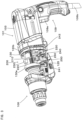
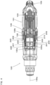
- FIG. 1 is a sectional view for illustrating the outline of the hammer drill 100.
- the hammer drill 100 is a hand-held work tool having a handgrip 109 designed to be held by a user.
- the hammer drill 100 is configured to perform hammering motion for a hammering operation on a workpiece by linearly driving a tool bit 119 in an axial direction of the tool bit 119 and to perform rotating motion for a drilling operation on the workpiece by rotationally driving the tool bit 119 around an axis of the tool bit 119.
- a user can appropriately set a drive mode of the tool bit 119 in the hammer drill 100 by operating a mode change lever (not shown).
- the hammer drill 100 according to this embodiment has a hammer drill mode in which the tool bit 119 is caused to perform the hammering motion and the rotating motion, and a drill mode in which the tool bit 119 is caused to perform only the rotating motion.
- a tool holder 159 is configured to make the tool bit 119 attachable and removable.
- the tool holder 159 extends in a specified longitudinal direction, and the longitudinal direction of the tool holder 159 defines a body longitudinal direction, which is a longitudinal direction of the hammer drill 100.
- the axial direction of the tool bit 119 is parallel to the body longitudinal direction.
- the hammer drill 100 and the tool bit 119 are examples that correspond to the "work tool” and the “tool accessory”, respectively, according to the present teachings.
- a front end side of the tool holder 159 in the body longitudinal direction is defined as a front side and a handgrip 109 side opposite to the front side is defined as a rear side.
- the tool holder 159 side is defined as an upper side and the handgrip 109 side is defined as a lower side.
- the left, right, upper and lower sides in FIG. 1 correspond to the front, rear, upper and lower sides of the hammer drill 100, respectively.
- the tool holder 159 is provided on a front end of a body housing 101, and the handgrip 109 designed to be held by a user is provided on a rear end of the body housing 101.
- a trigger 109a for energizing a driving motor 110 is provided on a front side of the handgrip 109.
- a power cable 109b for supplying current to the driving motor 110 is provided on a lower end of the handgrip 109.
- an outer shell of the hammer drill 100 is formed by the body housing 101.
- the body housing 101 mainly includes a motor housing 103, a gear housing 105 and an inner housing 130.
- the motor housing 103 and the gear housing 105 form a main part of the outer shell of the hammer drill 100.
- the body housing 101 is an example that corresponds to the "body” according to the present teachings.
- the driving motor 110 has an output shaft 111.
- the output shaft 111 is rotatably supported by a bearing 111a fixed to the inner housing 130 and a bearing 111b fixed to the motor housing 103.
- a fan 112 and a pinion gear 113 are provided on the output shaft 111 and can rotate together with the output shaft 111.
- the fan 112 sends air to the driving motor 110 by rotation of the output shaft 111 and cools the driving motor 110.
- the driving motor 110 is an example that corresponds to the "driving motor" according to the present teachings.
- FIG. 2 is an enlarged sectional view for illustrating the tool accessory driving mechanism.
- the tool accessory driving mechanism mainly includes a motion converting mechanism 120 and a striking mechanism 140 which serve to linearly drive the tool bit 119, and a rotation transmitting mechanism 150 for rotationally driving the tool bit 119.
- a mechanism formed by the motion converting mechanism 120 and the striking mechanism 140 is an example that corresponds to the "tool accessory driving mechanism" according to the present teachings.
- the rotation transmitting mechanism 150 has an intermediate shaft 116 that can rotate on a rotation axis 116c.
- the rotation axis 116c is parallel to the output shaft 111 of the driving motor 110 and a striking axis 140a (which is described below) defined by the tool accessory driving mechanism.
- the intermediate shaft 116 and the rotation axis 116c are examples that correspond to the "rotary shaft member" and the “rotation axis", respectively, according to the present teachings.
- front and rear end parts of the intermediate shaft 116 are mounted to the gear housing 105 via a bearing 116a and a bearing 116b, respectively.
- a driven gear 117 which engages with the pinion gear 113 of the driving motor 110, is provided on the rear end part of the intermediate shaft 116.
- a first gear 151 which engages with a second gear 153 integrally formed with a sleeve 129, is provided on the front end part of the intermediate shaft 116.
- the sleeve 129 is integrally connected to the tool holder 159 via a ring spring 159a. Further, a front end part of the sleeve 129 is mounted to the gear housing 105 via a bearing 129a and a rear end part of the sleeve 129 is mounted to the inner housing 130 via a bearing 129b, so that the sleeve 129 is rotatably disposed within the body housing 101.
- the motion converting mechanism 120 mainly includes a clutch cam 180, a rotary body 123 and a swinging shaft 125.
- the rotary body 123 is configured to rotate with respect to the intermediate shaft 116.
- the clutch cam 180 is spline-connected to the intermediate shaft 116, so that the clutch cam 180 can move in a direction of the rotation axis 116c and is caused to rotate by rotation of the intermediate shaft 116.
- the clutch cam 180 is moved in a front-rear direction along with user's operation of the mode change lever.
- Detailed description of the mode change lever is omitted for convenience sake.
- the clutch cam 180 When the hammer drill mode is selected with the mode change lever, the clutch cam 180 is moved rearward, and a clutch teeth 180a of the clutch cam 180 and a clutch teeth 123a of the rotary body 123 engage with each other. Therefore, in this case, the tool holder 159 is rotationally driven and the rotary body 123 is rotated, so that a piston 127 is driven as described below.
- FIGS. 1 and 2 show the state in the drill mode.
- the rotary body 123 has an outer peripheral surface 123c having a specified inclination angle with respect to the rotation axis 116c.
- the swinging shaft 125 includes: an annular part 125b which is mounted on the outer peripheral surface 123c of the rotary body 123 via a plurality of steel balls 123b and surrounds the rotary body 123; a shaft part 125a which protrudes upward from the annular part 125b and is connected to the piston 127 via a joint pin 126; and a projection 125c which protrudes downward from the opposite side (lower end) of the annular part 125b from the shaft part 125a and connected to a connecting member 250 which is described below.
- the shaft part 125a and the joint pin 126 are rotatably connected with respect to each other and form a tool accessory driving mechanism connection part.
- the projection 125c and the connecting member 250 are rotatably connected with respect to each other and form a connecting member connecting mechanism.
- the swinging shaft 125 is an example that corresponds to the "swinging member" according to the present teachings.
- the annular part 125b moves following inclination of the outer peripheral surface 123c which changes as the rotary body 123 rotates. Accordingly, the shaft part 125a is caused to swing in the front-rear direction along the rotation axis 116c.
- the tool accessory driving mechanism is then driven as described below by a linear motion component of the swinging motion of the shaft part 125a.
- the shaft part 125a and the projection 125c are arranged oppositely to each other with respect to the rotation axis 116c. Therefore, the projection 125c is turned rearward when the shaft part 125a is turned forward, while the projection 125c is turned forward when the shaft part 125a is turned rearward.
- the striking mechanism 140 mainly includes: the piston 127 that is formed by a bottomed cylindrical member and slidably disposed in a bore of the sleeve 129; a striking element in the form of a striker 143 that is slidably disposed in a bore of the piston 127; and an intermediate element in the form of an impact bolt 145 that is slidably disposed in a bore of the tool holder 159 and transmits kinetic energy of the striker 143 to the tool bit 119.
- An air chamber 127a is formed between the bottom of the piston 127 and the striker 143, and the striker 143 is linearly driven by pressure fluctuations caused in the air chamber 127a when the piston 127 reciprocates within the sleeve 129. Specifically, when the piston 127 moves forward and compresses air in the air chamber 127a, the striker 143 is pushed forward by expansion of the compressed air, collides with the impact bolt 145 and moves the tool bit 119 forward. On the other hand, when the piston moves rearward, the air in the air chamber 127a is expanded. Then the striker 143 is retracted rearward by negative pressure of the expanded air.
- the above-described operation of the striking mechanism 140 defines the striking axis 140a shown in FIG. 1 .
- the striking axis 140a is parallel to the rotation axis 116c.
- the striking axis 140a is an example that corresponds to the "driving axis" according to the present teachings.
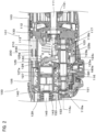
- FIG. 3 is an explanatory drawing for illustrating a main part of the vibration reducing mechanism 200.
- the vibration reducing mechanism 200 has a dynamic vibration reducer 210 and the connecting member 250.
- the vibration reducing mechanism 200, the dynamic vibration reducer 210 and the connecting member 250 are examples that correspond to the "vibration reducing mechanism", the “dynamic vibration reducer” and the “connecting member”, respectively, according to the present teachings.
- FIG. 4 is a sectional view taken along line I-I in FIG. 1 .
- the dynamic vibration reducer 210 includes: a plurality of shafts 220 that are arranged to extend between a front part 130a and a rear part 130b of the inner housing 130; a weight 230 through which the shafts 220 are inserted; and an elastic member 240 for biasing the weight 230.
- five such shafts 220 are used as shown in FIG. 6 , any number of the shafts 220 may be selected according to the structure of the dynamic vibration reducer 210 to be realized.
- the shafts 220 are arranged to extend in parallel to the striking axis 140a.
- the weight 230 has insertion holes 230a through which the shafts 220 extend.
- the shaft 220, the weight 230 and the elastic member 240 are examples that correspond to the "shaft", the "weight” and the “elastic member", respectively, according to the present teachings.
- the elastic member 240 is mounted on one or some of the shafts 220.
- the elastic member 240 is provided on each of a pair of the shafts 220 which are arranged oppositely to each other with respect to the striking axis 140a.
- FIG. 5 is an explanatory drawing for illustrating the shaft 220 on which the elastic member 240 is mounted.
- the elastic member 240 includes a first elastic member 241 disposed between the front part 130a of the inner housing 130 and a front side of the weight 230, and a second elastic member 242 disposed between the rear part 130b of the inner housing 130 and a rear side of the weight 230. With this structure, the weight 230 can reciprocally slide with respect to the shaft 220.
- FIG. 6 is a sectional view taken along line II-II in FIG. 1 .
- the weight 230 is arranged to surround the striking axis 140a around the striking axis 140a.
- the weight 230 is caused to easily reciprocate by vibration which is caused in a direction along the striking axis 140a when the striking mechanism 140 is driven.
- the dynamic vibration reducer 210 can effectively reduce vibration caused in the direction of the striking axis 140a.
- the weight 230 has a pair of end regions 231 each including an end. A region of the weight 230 between the end regions 231 forms an intermediate region 232.
- the connecting member 250 is arranged to surround the rotation axis 116c around the rotation axis 116c. This structure enables efficient arrangement of the connecting member 250 around the rotation axis 116c. Further, the connecting member 250 has a pair of end regions 251 each including an end. A region of the connecting member 250 between the end regions 251 forms an intermediate region 252. The end region 251 and the intermediate region 252 are examples that correspond to the "end region" and the "intermediate region", respectively, according to the present teachings.
- the end regions 251 of the connecting member 250 and the end regions 231 of the weight 230 are connected to rotate on a pivot axis 260a with respect to each other.
- a specific structure of connecting the connecting member 250 and the weight 230 is described below.
- the intermediate region 252 of the connecting member 250 has an intermediate hole 252a through which the projection 125c of the swinging shaft 125 is inserted. With this structure, the connecting member 250 may be moved in the front-rear direction by rotation of the swinging shaft 125.
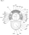
- FIG. 7 is an explanatory drawing for showing the structure of connecting the weight 230 and the connecting member 250.
- a circular cylindrical pivot shaft 260 is inserted through an end hole 231a formed in each of the end regions 231 of the weight 230 and an end hole 251a formed in each of the end regions 251 of the connecting member 250.
- a recess is formed in a region of the pivot shaft 260 outside of the connecting member 250, and a stopper ring 261 is mounted in the recess to prevent the connecting member 250 from slipping off.
- the weight 230 and the connecting member 250 are configured to rotate on the pivot axis 260a with respect to each other.
- the pivot axis 260a is an example that corresponds to the "pivot axis" according to the present teachings.
- FIG. 8 shows a state in which the shaft part 125a of the swinging shaft 125 is located to extend in a direction perpendicular to the rotation axis 116c.
- a state of the vibration reducing mechanism 200 shown in FIG. 8 is defined as a first state.
- a center line 250a connecting a center point between the pair of pivot shafts 260 and a center point of the intermediate hole 252a of the connecting member 250 has a specified inclination angle with respect to a rotation axis orthogonal line 116d passing through the center line 250a and extending perpendicularly to the rotation axis 116c.
- the pivot shafts 260 are arranged rearward of the intermediate hole 252a.
- the connecting member 250 has a communication region 253 extending over the end regions 251 and the intermediate region 252.
- the connecting member 250 can be efficiently arranged within a limited space, so that the hammer drill 100 can be reduced in size.
- the first state shown in FIG. 8 is defined as an initial state of the vibration reducing mechanism 200.
- the weight 230 is reciprocated together with the connecting member 250 and thereby reduces the vibration.
- the weight 230 linearly reciprocates by sliding on the shaft 220.
- the pivot shafts 260 reciprocate when the weight 230 linearly reciprocates, so that the connecting member 250 pivots on the intermediate hole 252a.
- FIG. 9 shows a state in which the shaft part 125a is inclined forward by rotation of the intermediate shaft 116. This state of the vibration reducing mechanism 200 is defined as a second state.
- the shaft part 125a moves the piston 127 forward and thus the tool bit 119 is moved forward.
- the projection 125c is inclined rearward, so that the weight 230 is moved rearward via the connecting member 250.
- the first elastic member 241 biases the weight 230 and thereby assists rearward movement of the weight 230.
- the second elastic member 242 is compressed by the weight 230.
- the swinging shaft 125 is caused to swing from the second state to a state in which the shaft part 125a is inclined rearward as shown in FIG. 10 via the first state.
- This state of the vibration reducing mechanism 200 shown in FIG. 10 is defined as a third state.
- the shaft part 125a In the third state, the shaft part 125a is inclined rearward and the projection 125c is inclined forward. Therefore, the shaft part 125a moves the piston 127 rearward, so that the air in the air chamber 127a is expanded and the striker 143 is moved rearward. Further, as the tool bit 119 is being pressed against the workpiece by the user, the tool bit 119 is moved rearward together with the impact bolt 145.
- the projection 125c is inclined forward, so that the weight 230 is moved forward via the connecting member 250.
- the second elastic member 242 biases the weight 230 and thereby assists forward movement of the weight 230.
- the first elastic member 241 is compressed by the weight 230.
- the vibration reducing mechanism 200 is configured to directly and forcibly reciprocate the weight 230 between the second state and the third state via the first state by swinging of the swinging shaft 125. Therefore, it can be said that the vibration reducing mechanism 200 includes a weight forcibly reciprocating mechanism.
- the vibration reducing mechanism 200 is configured to forcibly move the weight 230 along with the swinging of the swinging shaft 125, it can be said that the vibration reducing mechanism 200 serves as an assisting mechanism that is configured to shift the weight 230 from a stationary state to a moving state.
- the weight 230 can be reciprocated only by vibration caused in the body housing 101. Therefore, the reciprocating distance of the weight 230 may depend on the magnitude of vibration caused in the body housing 101.
- the weight 230 is forcibly reciprocated between the second state and the third state as described above via the connecting member 250. Specifically, in a state in which the amount of reciprocating movement of the weight 230 is small in the dynamic vibration reducer 210 formed only by the weight 230 and the elastic member 240, it can be said that the vibration reducing mechanism 200 forms a mechanism that is configured to increase the amount of reciprocating movement of the weight 230.
- the vibration reducing mechanism 200 forms a mechanism that is configured to control the amount of reciprocating movement of the weight 230.
- the connecting member 250 in the vibration reducing mechanism 200 is configured to rotate with respect to both the weight 230 and the swinging shaft 125, so that the connecting member 250 can linearly reciprocate the weight 230 by swinging of the swinging shaft 125. Further, with the structure in which the connecting member 250 can rotate with respect to both the weight 230 and the swinging shaft 125, it can also be said that the vibration reducing mechanism 200 forms a mechanism that is configured to change a phase in the reciprocating movement of the weight 230.
- the connecting member 250 which is caused to reciprocate by swinging of the swinging shaft 125 forms a counter weight.
- the vibration reducing mechanism 200 which is configured to exhibit various functions, can be provided to be suitable to the work tool 100 to be realized.
- the work tool according to the present teachings may have other structures.
- an electric reciprocating saw which is configured to perform a cutting operation on a workpiece such as wood by linearly driving the tool accessory may be used as the work tool.
- the handgrip 109 is formed in a cantilever shape extending downward, but the handgrip 109 may be formed in a loop shape.
- the output shaft 111 of the electric motor 110 is arranged in parallel to the rotation axis 116c, but the output shaft 111 may be arranged to cross the rotation axis 116c. In this case, the output shaft 111 and the intermediate shaft 116 may preferably be engaged with each other via a bevel gear.
Landscapes
- Engineering & Computer Science (AREA)
- Mechanical Engineering (AREA)
- Percussive Tools And Related Accessories (AREA)
Claims (12)
- Outil de travail (100) configuré pour effectuer une opération spécifiée sur une pièce en entraînant linéairement un accessoire d'outil (119), l'outil de travail comprenantun moteur d'entraînement (110),un élément d'arbre rotatif (116) configuré pour être entraîné en rotation par le moteur d'entraînement (110),un élément d'oscillation (125) configuré pour être amené à osciller par la rotation de l'élément d'arbre rotatif (116),un mécanisme d'entraînement d'accessoire d'outil (120, 140) configuré pour entraîner l'accessoire d'outil par l'oscillation de l'élément d'oscillation (125),un corps (101) logeant le moteur d'entraînement (110), l'élément d'arbre rotatif (116), l'élément d'oscillation (125) et le mécanisme d'entraînement d'accessoire d'outil, etun mécanisme de réduction de vibrations (200) configuré pour réduire les vibrations causées dans le corps (101), dans lequel le mécanisme de réduction de vibrations comprend un réducteur de vibrations dynamique (210) ayant un élément élastique (240) et un poids (230), le poids (230) étant sollicité par l'élément élastique (240) et ayant un mouvement alternatif,dans lequelle mécanisme de réduction de vibrations (200) comprend en outre un élément de liaison (250) reliant le poids (230) et l'élément d'oscillation (125), etle mécanisme de réduction de vibrations (200) est configuré pour provoquer un mouvement alternatif direct et forcé du le poids (230) par l'intermédiaire de l'élément de liaison (250) en faisant osciller l'élément d'oscillation (125), etdans lequel le poids (230) et l'élément de liaison (250) sont reliés de manière à pouvoir tourner sur un axe de pivotement (260a) l'un par rapport à l'autre.
- Outil de travail (100) tel que défini dans la revendication 1, dans lequel le poids est disposé sur un arbre (220) et configuré pour glisser par rapport à l'arbre (220), l'arbre (220) s'étendant dans une direction parallèle à l'axe d'entraînement (140a).
- Outil de travail (100) configuré pour effectuer une opération spécifiée sur une pièce en entraînant linéairement un accessoire d'outil (119), l'outil de travail comprenantun moteur d'entraînement (110),un élément d'arbre rotatif (116) configuré pour être entraîné en rotation par le moteur d'entraînement (110),un élément d'oscillation (125) configuré pour être amené à osciller par la rotation de l'élément d'arbre rotatif (116),un mécanisme d'entraînement d'accessoire d'outil (120, 140) configuré pour entraîner l'accessoire d'outil par l'oscillation de l'élément d'oscillation (125),un corps (101) logeant le moteur d'entraînement (110), l'élément d'arbre rotatif (116), l'élément d'oscillation (125) et le mécanisme d'entraînement d'accessoire d'outil, etun mécanisme de réduction de vibrations (200) configuré pour réduire les vibrations causées dans le corps (101), dans lequel le mécanisme de réduction de vibrations comprend un réducteur de vibrations dynamique (210) ayant un élément élastique (240) et un poids (230), le poids (230) étant sollicité par l'élément élastique (240) et ayant un mouvement alternatif,dans lequelle mécanisme de réduction de vibrations (200) comprend en outre un élément de liaison (250) reliant le poids (230) et l'élément d'oscillation (125), etle mécanisme de réduction de vibrations (200) est configuré pour provoquer un mouvement alternatif direct et forcé du poids (230) par l'intermédiaire de l'élément de liaison (250) en faisant osciller l'élément d'oscillation (125), etdans lequel le poids est disposé sur un arbre (220) et configuré pour glisser par rapport à l'arbre (220), l'arbre (220) s'étendant dans une direction parallèle à l'axe d'entraînement (140a).
- Outil de travail (100) tel que défini dans la revendication 3, dans lequel le poids (230) et l'élément de liaison (250) sont reliés de manière à pouvoir tourner sur un axe de pivotement (260a) l'un par rapport à l'autre.
- Outil de travail (100) tel que défini dans l'une quelconque des revendications 1 à 4, dans lequel le mécanisme d'entraînement d'accessoire d'outil (120, 140) définit un axe d'entraînement (140a), et le poids (230) est configuré pour entourer l'axe d'entraînement (140a) autour de l'axe d'entraînement (140a).
- Outil de travail (100) tel que défini dans l'une quelconque des revendications 1 à 5, dans lequel l'élément d'arbre rotatif (116) définit un axe de rotation (116c), et l'élément de liaison (250) est configuré pour entourer l'axe de rotation (116c) autour de l'axe de rotation (116c).
- Outil de travail (100) tel que défini dans la revendication 6, dans lequel l'élément de liaison (250) a une paire de régions d'extrémité (251) et une région intermédiaire (252), la région intermédiaire (252) étant formée entre la paire de régions d'extrémité (251) et étant connectée à l'élément d'oscillation (125).
- Outil de travail (100) tel que défini dans l'une quelconque des revendications 1 à 7, dans lequel le mécanisme de réduction de vibrations (200) est également configuré pour servir de mécanisme d'assistance configuré pour déplacer le poids (230) à partir d'un état stationnaire par un mouvement alternatif du poids (230) par l'intermédiaire de l'élément de liaison (250) en même temps que l'oscillation de l'élément d'oscillation (125).
- Outil de travail (100) tel que défini dans l'une quelconque des revendications 1 à 7, dans lequel le mécanisme de réduction de vibrations (200) est également configuré pour servir de mécanisme configuré pour augmenter une quantité de mouvement alternatif du poids (230) en entraînant le poids (230) dans un mouvement alternatif par l'intermédiaire de l'élément de liaison (250) en même temps l'oscillation de l'élément d'oscillation (125).
- Outil de travail (100) tel que défini dans l'une quelconque des revendications 1 à 7, dans lequel le mécanisme de réduction de vibrations (200) est également configuré pour servir de mécanisme configuré pour changer une phase dans le mouvement alternatif du poids (230) en entraînant le poids (230) dans un mouvement alternatif par l'intermédiaire de l'élément de liaison (250) en même temps que l'oscillation de l'élément d'oscillation (125).
- Outil de travail (100) tel que défini dans l'une quelconque des revendications 1 à 7, dans lequel le mécanisme de réduction de vibrations (200) est également configuré pour servir de mécanisme configuré pour contrôler une quantité de mouvement alternatif du poids (230) en entraînant le poids (230) dans un mouvement alternatif par l'intermédiaire de l'élément de liaison (250) en même temps que l'oscillation de l'élément d'oscillation (125).
- Outil de travail (100) tel que défini dans l'une quelconque des revendications 1 à 7, dans lequel l'élément de liaison (250) forme un contrepoids configuré pour être entraîné dans un mouvement alternatif avec l'oscillation de l'élément d'oscillation (125).
Applications Claiming Priority (2)
| Application Number | Priority Date | Filing Date | Title |
|---|---|---|---|
| JP2015015503A JP6510250B2 (ja) | 2015-01-29 | 2015-01-29 | 作業工具 |
| PCT/JP2016/052392 WO2016121837A1 (fr) | 2015-01-29 | 2016-01-27 | Outil de travail |
Publications (3)
| Publication Number | Publication Date |
|---|---|
| EP3235599A1 EP3235599A1 (fr) | 2017-10-25 |
| EP3235599A4 EP3235599A4 (fr) | 2018-08-29 |
| EP3235599B1 true EP3235599B1 (fr) | 2024-11-06 |
Family
ID=56543445
Family Applications (1)
| Application Number | Title | Priority Date | Filing Date |
|---|---|---|---|
| EP16743440.6A Active EP3235599B1 (fr) | 2015-01-29 | 2016-01-27 | Outil de travail |
Country Status (5)
| Country | Link |
|---|---|
| US (1) | US10518400B2 (fr) |
| EP (1) | EP3235599B1 (fr) |
| JP (1) | JP6510250B2 (fr) |
| CN (1) | CN107206584B (fr) |
| WO (1) | WO2016121837A1 (fr) |
Families Citing this family (6)
| Publication number | Priority date | Publication date | Assignee | Title |
|---|---|---|---|---|
| JP6987599B2 (ja) * | 2017-10-20 | 2022-01-05 | 株式会社マキタ | 打撃工具 |
| JP7251612B2 (ja) * | 2019-03-28 | 2023-04-04 | 工機ホールディングス株式会社 | 打撃作業機 |
| US11318596B2 (en) * | 2019-10-21 | 2022-05-03 | Makita Corporation | Power tool having hammer mechanism |
| US11845168B2 (en) * | 2019-11-01 | 2023-12-19 | Makita Corporation | Reciprocating tool |
| US11642769B2 (en) * | 2021-02-22 | 2023-05-09 | Makita Corporation | Power tool having a hammer mechanism |
| JP2025025056A (ja) * | 2023-08-08 | 2025-02-21 | 株式会社マキタ | 電動工具 |
Family Cites Families (24)
| Publication number | Priority date | Publication date | Assignee | Title |
|---|---|---|---|---|
| GB2129733A (en) * | 1982-10-27 | 1984-05-23 | Jean Walton | More-vibration-free concrete breakers and percussion drills |
| SU1617139A1 (ru) * | 1988-08-09 | 1990-12-30 | Московское Научно-Производственное Объединение По Механизированному Строительному Инструменту И Отделочным Машинам | Компрессионно-вакуумна машина ударного действи |
| US5555626A (en) * | 1995-11-27 | 1996-09-17 | S-B Power Tool Company | Reciprocating drive mechanism |
| DE19851888C1 (de) * | 1998-11-11 | 2000-07-13 | Metabowerke Kg | Bohrhammer |
| JP4195818B2 (ja) * | 2003-01-16 | 2008-12-17 | 株式会社マキタ | 電動ハンマ |
| DE602004027011D1 (en) * | 2003-03-21 | 2010-06-17 | Black & Decker Inc | Uziervorrichtung |
| DE602004026134D1 (de) * | 2003-04-01 | 2010-05-06 | Makita Corp | Kraftwerkzeug |
| JP4155857B2 (ja) * | 2003-04-01 | 2008-09-24 | 株式会社マキタ | 作業工具 |
| DE602004026243D1 (de) * | 2003-05-09 | 2010-05-12 | Makita Corp | Elektrowerkzeug |
| US7604071B2 (en) * | 2004-04-30 | 2009-10-20 | Makita Corporation | Power tool with vibration reducing means |
| JP2007175839A (ja) * | 2005-12-28 | 2007-07-12 | Hitachi Koki Co Ltd | 打撃工具 |
| JP5135722B2 (ja) * | 2006-06-19 | 2013-02-06 | 株式会社ジェイテクト | 車両用操舵装置 |
| JP4863942B2 (ja) * | 2006-08-24 | 2012-01-25 | 株式会社マキタ | 打撃工具 |
| JP5009059B2 (ja) * | 2007-06-15 | 2012-08-22 | 株式会社マキタ | 打撃工具 |
| US7832498B2 (en) * | 2007-06-15 | 2010-11-16 | Makita Corporation | Impact tool |
| US7806201B2 (en) * | 2007-07-24 | 2010-10-05 | Makita Corporation | Power tool with dynamic vibration damping |
| DE102007061716A1 (de) * | 2007-12-19 | 2009-06-25 | Robert Bosch Gmbh | Taumelantrieb einer Handwerkzeugmaschine |
| JP2010250145A (ja) | 2009-04-17 | 2010-11-04 | Seiko Epson Corp | 表示装置の検査装置及び検査方法 |
| JP5345893B2 (ja) | 2009-05-08 | 2013-11-20 | 株式会社マキタ | 打撃工具 |
| US9618257B2 (en) * | 2010-06-09 | 2017-04-11 | Quantum Design International, Inc. | Gas-flow cryostat for dynamic temperature regulation using a fluid level sensor |
| DE102011077220A1 (de) * | 2010-12-21 | 2012-06-21 | Robert Bosch Gmbh | Elektrohandwerkzeug |
| US9156152B2 (en) * | 2011-08-31 | 2015-10-13 | Makita Corporation | Impact tool having counter weight that reduces vibration |
| JP5859249B2 (ja) * | 2011-08-31 | 2016-02-10 | 株式会社マキタ | 打撃工具 |
| DE102013212554B4 (de) * | 2013-06-28 | 2023-12-14 | Robert Bosch Gmbh | Handwerkzeugmaschinenantriebsvorrichtung |
-
2015
- 2015-01-29 JP JP2015015503A patent/JP6510250B2/ja active Active
-
2016
- 2016-01-27 CN CN201680007504.3A patent/CN107206584B/zh active Active
- 2016-01-27 EP EP16743440.6A patent/EP3235599B1/fr active Active
- 2016-01-27 US US15/545,972 patent/US10518400B2/en active Active
- 2016-01-27 WO PCT/JP2016/052392 patent/WO2016121837A1/fr not_active Ceased
Also Published As
| Publication number | Publication date |
|---|---|
| US10518400B2 (en) | 2019-12-31 |
| EP3235599A4 (fr) | 2018-08-29 |
| CN107206584A (zh) | 2017-09-26 |
| EP3235599A1 (fr) | 2017-10-25 |
| JP2016137559A (ja) | 2016-08-04 |
| CN107206584B (zh) | 2021-06-29 |
| US20180001463A1 (en) | 2018-01-04 |
| JP6510250B2 (ja) | 2019-05-08 |
| WO2016121837A1 (fr) | 2016-08-04 |
Similar Documents
| Publication | Publication Date | Title |
|---|---|---|
| EP3235599A1 (fr) | Outil de travail | |
| US10500706B2 (en) | Power tool | |
| JP6367617B2 (ja) | 往復動式作業工具 | |
| JP4270887B2 (ja) | 電動往復動式工具 | |
| JP6096593B2 (ja) | 往復動式作業工具 | |
| JP5345893B2 (ja) | 打撃工具 | |
| EP1724067B1 (fr) | Outil à impact motorisé | |
| JP5294726B2 (ja) | 手持式作業工具 | |
| CN109421026A (zh) | 作业工具 | |
| WO2015190355A1 (fr) | Outil à choc | |
| BR102012013240B1 (pt) | ferramenta elétrica | |
| CN107107322B (zh) | 冲击工具 | |
| JP2017042887A (ja) | 打撃工具 | |
| JP6517634B2 (ja) | 打撃工具 | |
| US9956675B2 (en) | Hammer drive mechanism | |
| WO2015045734A1 (fr) | Outil à impact | |
| JP2006110685A (ja) | 往復作動式作業工具 | |
| JP6348337B2 (ja) | 往復動式作業工具 | |
| EP3812097B1 (fr) | Marteau rotatif | |
| JP6517633B2 (ja) | 打撃工具 | |
| JP2007203388A (ja) | 打撃工具 | |
| JP2013091117A (ja) | 打撃工具 | |
| JP6335049B2 (ja) | 打撃工具 | |
| JP2014172141A (ja) | 打撃工具 | |
| JP2021074796A (ja) | 打撃工具 |
Legal Events
| Date | Code | Title | Description |
|---|---|---|---|
| STAA | Information on the status of an ep patent application or granted ep patent |
Free format text: STATUS: THE INTERNATIONAL PUBLICATION HAS BEEN MADE |
|
| PUAI | Public reference made under article 153(3) epc to a published international application that has entered the european phase |
Free format text: ORIGINAL CODE: 0009012 |
|
| STAA | Information on the status of an ep patent application or granted ep patent |
Free format text: STATUS: REQUEST FOR EXAMINATION WAS MADE |
|
| 17P | Request for examination filed |
Effective date: 20170720 |
|
| AK | Designated contracting states |
Kind code of ref document: A1 Designated state(s): AL AT BE BG CH CY CZ DE DK EE ES FI FR GB GR HR HU IE IS IT LI LT LU LV MC MK MT NL NO PL PT RO RS SE SI SK SM TR |
|
| AX | Request for extension of the european patent |
Extension state: BA ME |
|
| DAV | Request for validation of the european patent (deleted) | ||
| DAX | Request for extension of the european patent (deleted) | ||
| A4 | Supplementary search report drawn up and despatched |
Effective date: 20180801 |
|
| RIC1 | Information provided on ipc code assigned before grant |
Ipc: B25D 11/06 20060101ALI20180726BHEP Ipc: B25D 11/10 20060101ALI20180726BHEP Ipc: B25D 17/24 20060101AFI20180726BHEP |
|
| STAA | Information on the status of an ep patent application or granted ep patent |
Free format text: STATUS: EXAMINATION IS IN PROGRESS |
|
| 17Q | First examination report despatched |
Effective date: 20220523 |
|
| GRAP | Despatch of communication of intention to grant a patent |
Free format text: ORIGINAL CODE: EPIDOSNIGR1 |
|
| STAA | Information on the status of an ep patent application or granted ep patent |
Free format text: STATUS: GRANT OF PATENT IS INTENDED |
|
| INTG | Intention to grant announced |
Effective date: 20240619 |
|
| RIN1 | Information on inventor provided before grant (corrected) |
Inventor name: FURUSAWA, MASANORI |
|
| GRAJ | Information related to disapproval of communication of intention to grant by the applicant or resumption of examination proceedings by the epo deleted |
Free format text: ORIGINAL CODE: EPIDOSDIGR1 |
|
| STAA | Information on the status of an ep patent application or granted ep patent |
Free format text: STATUS: EXAMINATION IS IN PROGRESS |
|
| GRAP | Despatch of communication of intention to grant a patent |
Free format text: ORIGINAL CODE: EPIDOSNIGR1 |
|
| STAA | Information on the status of an ep patent application or granted ep patent |
Free format text: STATUS: GRANT OF PATENT IS INTENDED |
|
| INTC | Intention to grant announced (deleted) | ||
| INTG | Intention to grant announced |
Effective date: 20240822 |
|
| GRAS | Grant fee paid |
Free format text: ORIGINAL CODE: EPIDOSNIGR3 |
|
| GRAA | (expected) grant |
Free format text: ORIGINAL CODE: 0009210 |
|
| STAA | Information on the status of an ep patent application or granted ep patent |
Free format text: STATUS: THE PATENT HAS BEEN GRANTED |
|
| AK | Designated contracting states |
Kind code of ref document: B1 Designated state(s): AL AT BE BG CH CY CZ DE DK EE ES FI FR GB GR HR HU IE IS IT LI LT LU LV MC MK MT NL NO PL PT RO RS SE SI SK SM TR |
|
| REG | Reference to a national code |
Ref country code: GB Ref legal event code: FG4D |
|
| REG | Reference to a national code |
Ref country code: CH Ref legal event code: EP |
|
| REG | Reference to a national code |
Ref country code: DE Ref legal event code: R096 Ref document number: 602016090128 Country of ref document: DE |
|
| REG | Reference to a national code |
Ref country code: IE Ref legal event code: FG4D |
|
| REG | Reference to a national code |
Ref country code: LT Ref legal event code: MG9D |
|
| REG | Reference to a national code |
Ref country code: NL Ref legal event code: MP Effective date: 20241106 |
|
| PG25 | Lapsed in a contracting state [announced via postgrant information from national office to epo] |
Ref country code: PT Free format text: LAPSE BECAUSE OF FAILURE TO SUBMIT A TRANSLATION OF THE DESCRIPTION OR TO PAY THE FEE WITHIN THE PRESCRIBED TIME-LIMIT Effective date: 20250306 Ref country code: IS Free format text: LAPSE BECAUSE OF FAILURE TO SUBMIT A TRANSLATION OF THE DESCRIPTION OR TO PAY THE FEE WITHIN THE PRESCRIBED TIME-LIMIT Effective date: 20250306 Ref country code: HR Free format text: LAPSE BECAUSE OF FAILURE TO SUBMIT A TRANSLATION OF THE DESCRIPTION OR TO PAY THE FEE WITHIN THE PRESCRIBED TIME-LIMIT Effective date: 20241106 |
|
| PG25 | Lapsed in a contracting state [announced via postgrant information from national office to epo] |
Ref country code: FI Free format text: LAPSE BECAUSE OF FAILURE TO SUBMIT A TRANSLATION OF THE DESCRIPTION OR TO PAY THE FEE WITHIN THE PRESCRIBED TIME-LIMIT Effective date: 20241106 Ref country code: NL Free format text: LAPSE BECAUSE OF FAILURE TO SUBMIT A TRANSLATION OF THE DESCRIPTION OR TO PAY THE FEE WITHIN THE PRESCRIBED TIME-LIMIT Effective date: 20241106 |
|
| REG | Reference to a national code |
Ref country code: AT Ref legal event code: MK05 Ref document number: 1738869 Country of ref document: AT Kind code of ref document: T Effective date: 20241106 |
|
| PG25 | Lapsed in a contracting state [announced via postgrant information from national office to epo] |
Ref country code: BG Free format text: LAPSE BECAUSE OF FAILURE TO SUBMIT A TRANSLATION OF THE DESCRIPTION OR TO PAY THE FEE WITHIN THE PRESCRIBED TIME-LIMIT Effective date: 20241106 |
|
| PG25 | Lapsed in a contracting state [announced via postgrant information from national office to epo] |
Ref country code: ES Free format text: LAPSE BECAUSE OF FAILURE TO SUBMIT A TRANSLATION OF THE DESCRIPTION OR TO PAY THE FEE WITHIN THE PRESCRIBED TIME-LIMIT Effective date: 20241106 |
|
| PG25 | Lapsed in a contracting state [announced via postgrant information from national office to epo] |
Ref country code: NO Free format text: LAPSE BECAUSE OF FAILURE TO SUBMIT A TRANSLATION OF THE DESCRIPTION OR TO PAY THE FEE WITHIN THE PRESCRIBED TIME-LIMIT Effective date: 20250206 |
|
| PG25 | Lapsed in a contracting state [announced via postgrant information from national office to epo] |
Ref country code: AT Free format text: LAPSE BECAUSE OF FAILURE TO SUBMIT A TRANSLATION OF THE DESCRIPTION OR TO PAY THE FEE WITHIN THE PRESCRIBED TIME-LIMIT Effective date: 20241106 Ref country code: LV Free format text: LAPSE BECAUSE OF FAILURE TO SUBMIT A TRANSLATION OF THE DESCRIPTION OR TO PAY THE FEE WITHIN THE PRESCRIBED TIME-LIMIT Effective date: 20241106 Ref country code: GR Free format text: LAPSE BECAUSE OF FAILURE TO SUBMIT A TRANSLATION OF THE DESCRIPTION OR TO PAY THE FEE WITHIN THE PRESCRIBED TIME-LIMIT Effective date: 20250207 |
|
| PG25 | Lapsed in a contracting state [announced via postgrant information from national office to epo] |
Ref country code: PL Free format text: LAPSE BECAUSE OF FAILURE TO SUBMIT A TRANSLATION OF THE DESCRIPTION OR TO PAY THE FEE WITHIN THE PRESCRIBED TIME-LIMIT Effective date: 20241106 |
|
| PG25 | Lapsed in a contracting state [announced via postgrant information from national office to epo] |
Ref country code: RS Free format text: LAPSE BECAUSE OF FAILURE TO SUBMIT A TRANSLATION OF THE DESCRIPTION OR TO PAY THE FEE WITHIN THE PRESCRIBED TIME-LIMIT Effective date: 20250206 |
|
| PG25 | Lapsed in a contracting state [announced via postgrant information from national office to epo] |
Ref country code: SM Free format text: LAPSE BECAUSE OF FAILURE TO SUBMIT A TRANSLATION OF THE DESCRIPTION OR TO PAY THE FEE WITHIN THE PRESCRIBED TIME-LIMIT Effective date: 20241106 |
|
| PG25 | Lapsed in a contracting state [announced via postgrant information from national office to epo] |
Ref country code: DK Free format text: LAPSE BECAUSE OF FAILURE TO SUBMIT A TRANSLATION OF THE DESCRIPTION OR TO PAY THE FEE WITHIN THE PRESCRIBED TIME-LIMIT Effective date: 20241106 |
|
| PG25 | Lapsed in a contracting state [announced via postgrant information from national office to epo] |
Ref country code: EE Free format text: LAPSE BECAUSE OF FAILURE TO SUBMIT A TRANSLATION OF THE DESCRIPTION OR TO PAY THE FEE WITHIN THE PRESCRIBED TIME-LIMIT Effective date: 20241106 |
|
| PG25 | Lapsed in a contracting state [announced via postgrant information from national office to epo] |
Ref country code: RO Free format text: LAPSE BECAUSE OF FAILURE TO SUBMIT A TRANSLATION OF THE DESCRIPTION OR TO PAY THE FEE WITHIN THE PRESCRIBED TIME-LIMIT Effective date: 20241106 |
|
| PG25 | Lapsed in a contracting state [announced via postgrant information from national office to epo] |
Ref country code: SK Free format text: LAPSE BECAUSE OF FAILURE TO SUBMIT A TRANSLATION OF THE DESCRIPTION OR TO PAY THE FEE WITHIN THE PRESCRIBED TIME-LIMIT Effective date: 20241106 |
|
| PG25 | Lapsed in a contracting state [announced via postgrant information from national office to epo] |
Ref country code: CZ Free format text: LAPSE BECAUSE OF FAILURE TO SUBMIT A TRANSLATION OF THE DESCRIPTION OR TO PAY THE FEE WITHIN THE PRESCRIBED TIME-LIMIT Effective date: 20241106 |
|
| PG25 | Lapsed in a contracting state [announced via postgrant information from national office to epo] |
Ref country code: IT Free format text: LAPSE BECAUSE OF FAILURE TO SUBMIT A TRANSLATION OF THE DESCRIPTION OR TO PAY THE FEE WITHIN THE PRESCRIBED TIME-LIMIT Effective date: 20241106 |
|
| REG | Reference to a national code |
Ref country code: DE Ref legal event code: R097 Ref document number: 602016090128 Country of ref document: DE |
|
| REG | Reference to a national code |
Ref country code: CH Ref legal event code: PL |
|
| PG25 | Lapsed in a contracting state [announced via postgrant information from national office to epo] |
Ref country code: SE Free format text: LAPSE BECAUSE OF FAILURE TO SUBMIT A TRANSLATION OF THE DESCRIPTION OR TO PAY THE FEE WITHIN THE PRESCRIBED TIME-LIMIT Effective date: 20241106 |
|
| PLBE | No opposition filed within time limit |
Free format text: ORIGINAL CODE: 0009261 |
|
| STAA | Information on the status of an ep patent application or granted ep patent |
Free format text: STATUS: NO OPPOSITION FILED WITHIN TIME LIMIT |
|
| PG25 | Lapsed in a contracting state [announced via postgrant information from national office to epo] |
Ref country code: MC Free format text: LAPSE BECAUSE OF FAILURE TO SUBMIT A TRANSLATION OF THE DESCRIPTION OR TO PAY THE FEE WITHIN THE PRESCRIBED TIME-LIMIT Effective date: 20241106 Ref country code: LU Free format text: LAPSE BECAUSE OF NON-PAYMENT OF DUE FEES Effective date: 20250127 |
|
| 26N | No opposition filed |
Effective date: 20250807 |
|
| PG25 | Lapsed in a contracting state [announced via postgrant information from national office to epo] |
Ref country code: BE Free format text: LAPSE BECAUSE OF NON-PAYMENT OF DUE FEES Effective date: 20250131 |
|
| PG25 | Lapsed in a contracting state [announced via postgrant information from national office to epo] |
Ref country code: CH Free format text: LAPSE BECAUSE OF NON-PAYMENT OF DUE FEES Effective date: 20250131 |
|
| REG | Reference to a national code |
Ref country code: BE Ref legal event code: MM Effective date: 20250131 |
|
| PGFP | Annual fee paid to national office [announced via postgrant information from national office to epo] |
Ref country code: GB Payment date: 20251204 Year of fee payment: 11 |
|
| PGFP | Annual fee paid to national office [announced via postgrant information from national office to epo] |
Ref country code: FR Payment date: 20251128 Year of fee payment: 11 |
|
| PG25 | Lapsed in a contracting state [announced via postgrant information from national office to epo] |
Ref country code: IE Free format text: LAPSE BECAUSE OF NON-PAYMENT OF DUE FEES Effective date: 20250127 |
|
| PGFP | Annual fee paid to national office [announced via postgrant information from national office to epo] |
Ref country code: DE Payment date: 20251203 Year of fee payment: 11 |