EP3235943A1 - Sèche-linge comprenant une pompe à chaleur et entraînement associé - Google Patents
Sèche-linge comprenant une pompe à chaleur et entraînement associé Download PDFInfo
- Publication number
- EP3235943A1 EP3235943A1 EP17163068.4A EP17163068A EP3235943A1 EP 3235943 A1 EP3235943 A1 EP 3235943A1 EP 17163068 A EP17163068 A EP 17163068A EP 3235943 A1 EP3235943 A1 EP 3235943A1
- Authority
- EP
- European Patent Office
- Prior art keywords
- floor assembly
- drying apparatus
- bolt
- grommets
- laundry drying
- Prior art date
- Legal status (The legal status is an assumption and is not a legal conclusion. Google has not performed a legal analysis and makes no representation as to the accuracy of the status listed.)
- Granted
Links
Images



Classifications
-
- D—TEXTILES; PAPER
- D06—TREATMENT OF TEXTILES OR THE LIKE; LAUNDERING; FLEXIBLE MATERIALS NOT OTHERWISE PROVIDED FOR
- D06F—LAUNDERING, DRYING, IRONING, PRESSING OR FOLDING TEXTILE ARTICLES
- D06F58/00—Domestic laundry dryers
- D06F58/20—General details of domestic laundry dryers
-
- F—MECHANICAL ENGINEERING; LIGHTING; HEATING; WEAPONS; BLASTING
- F16—ENGINEERING ELEMENTS AND UNITS; GENERAL MEASURES FOR PRODUCING AND MAINTAINING EFFECTIVE FUNCTIONING OF MACHINES OR INSTALLATIONS; THERMAL INSULATION IN GENERAL
- F16B—DEVICES FOR FASTENING OR SECURING CONSTRUCTIONAL ELEMENTS OR MACHINE PARTS TOGETHER, e.g. NAILS, BOLTS, CIRCLIPS, CLAMPS, CLIPS OR WEDGES; JOINTS OR JOINTING
- F16B5/00—Joining sheets or plates, e.g. panels, to one another or to strips or bars parallel to them
- F16B5/02—Joining sheets or plates, e.g. panels, to one another or to strips or bars parallel to them by means of fastening members using screw-thread
- F16B5/0241—Joining sheets or plates, e.g. panels, to one another or to strips or bars parallel to them by means of fastening members using screw-thread with the possibility for the connection to absorb deformation, e.g. thermal or vibrational
-
- D—TEXTILES; PAPER
- D06—TREATMENT OF TEXTILES OR THE LIKE; LAUNDERING; FLEXIBLE MATERIALS NOT OTHERWISE PROVIDED FOR
- D06F—LAUNDERING, DRYING, IRONING, PRESSING OR FOLDING TEXTILE ARTICLES
- D06F37/00—Details specific to washing machines covered by groups D06F21/00 - D06F25/00
- D06F37/20—Mountings, e.g. resilient mountings, for the rotary receptacle, motor, tub or casing; Preventing or damping vibrations
-
- D—TEXTILES; PAPER
- D06—TREATMENT OF TEXTILES OR THE LIKE; LAUNDERING; FLEXIBLE MATERIALS NOT OTHERWISE PROVIDED FOR
- D06F—LAUNDERING, DRYING, IRONING, PRESSING OR FOLDING TEXTILE ARTICLES
- D06F58/00—Domestic laundry dryers
- D06F58/20—General details of domestic laundry dryers
- D06F58/206—Heat pump arrangements
-
- F—MECHANICAL ENGINEERING; LIGHTING; HEATING; WEAPONS; BLASTING
- F16—ENGINEERING ELEMENTS AND UNITS; GENERAL MEASURES FOR PRODUCING AND MAINTAINING EFFECTIVE FUNCTIONING OF MACHINES OR INSTALLATIONS; THERMAL INSULATION IN GENERAL
- F16B—DEVICES FOR FASTENING OR SECURING CONSTRUCTIONAL ELEMENTS OR MACHINE PARTS TOGETHER, e.g. NAILS, BOLTS, CIRCLIPS, CLAMPS, CLIPS OR WEDGES; JOINTS OR JOINTING
- F16B23/00—Specially shaped nuts or heads of bolts or screws for rotations by a tool
- F16B23/0007—Specially shaped nuts or heads of bolts or screws for rotations by a tool characterised by the shape of the recess or the protrusion engaging the tool
- F16B23/0023—Specially shaped nuts or heads of bolts or screws for rotations by a tool characterised by the shape of the recess or the protrusion engaging the tool substantially cross-shaped
-
- F—MECHANICAL ENGINEERING; LIGHTING; HEATING; WEAPONS; BLASTING
- F16—ENGINEERING ELEMENTS AND UNITS; GENERAL MEASURES FOR PRODUCING AND MAINTAINING EFFECTIVE FUNCTIONING OF MACHINES OR INSTALLATIONS; THERMAL INSULATION IN GENERAL
- F16B—DEVICES FOR FASTENING OR SECURING CONSTRUCTIONAL ELEMENTS OR MACHINE PARTS TOGETHER, e.g. NAILS, BOLTS, CIRCLIPS, CLAMPS, CLIPS OR WEDGES; JOINTS OR JOINTING
- F16B23/00—Specially shaped nuts or heads of bolts or screws for rotations by a tool
- F16B23/0007—Specially shaped nuts or heads of bolts or screws for rotations by a tool characterised by the shape of the recess or the protrusion engaging the tool
- F16B23/003—Specially shaped nuts or heads of bolts or screws for rotations by a tool characterised by the shape of the recess or the protrusion engaging the tool star-shaped or multi-lobular, e.g. Torx-type, twelve-point star
-
- F—MECHANICAL ENGINEERING; LIGHTING; HEATING; WEAPONS; BLASTING
- F16—ENGINEERING ELEMENTS AND UNITS; GENERAL MEASURES FOR PRODUCING AND MAINTAINING EFFECTIVE FUNCTIONING OF MACHINES OR INSTALLATIONS; THERMAL INSULATION IN GENERAL
- F16B—DEVICES FOR FASTENING OR SECURING CONSTRUCTIONAL ELEMENTS OR MACHINE PARTS TOGETHER, e.g. NAILS, BOLTS, CIRCLIPS, CLAMPS, CLIPS OR WEDGES; JOINTS OR JOINTING
- F16B23/00—Specially shaped nuts or heads of bolts or screws for rotations by a tool
- F16B23/0007—Specially shaped nuts or heads of bolts or screws for rotations by a tool characterised by the shape of the recess or the protrusion engaging the tool
- F16B23/0038—Specially shaped nuts or heads of bolts or screws for rotations by a tool characterised by the shape of the recess or the protrusion engaging the tool substantially prismatic with up to six edges, e.g. triangular, square, pentagonal, Allen-type cross-sections
-
- F—MECHANICAL ENGINEERING; LIGHTING; HEATING; WEAPONS; BLASTING
- F16—ENGINEERING ELEMENTS AND UNITS; GENERAL MEASURES FOR PRODUCING AND MAINTAINING EFFECTIVE FUNCTIONING OF MACHINES OR INSTALLATIONS; THERMAL INSULATION IN GENERAL
- F16B—DEVICES FOR FASTENING OR SECURING CONSTRUCTIONAL ELEMENTS OR MACHINE PARTS TOGETHER, e.g. NAILS, BOLTS, CIRCLIPS, CLAMPS, CLIPS OR WEDGES; JOINTS OR JOINTING
- F16B25/00—Screws that cut thread in the body into which they are screwed, e.g. wood screws
- F16B25/001—Screws that cut thread in the body into which they are screwed, e.g. wood screws characterised by the material of the body into which the screw is screwed
- F16B25/0015—Screws that cut thread in the body into which they are screwed, e.g. wood screws characterised by the material of the body into which the screw is screwed the material being a soft organic material, e.g. wood or plastic
-
- F—MECHANICAL ENGINEERING; LIGHTING; HEATING; WEAPONS; BLASTING
- F16—ENGINEERING ELEMENTS AND UNITS; GENERAL MEASURES FOR PRODUCING AND MAINTAINING EFFECTIVE FUNCTIONING OF MACHINES OR INSTALLATIONS; THERMAL INSULATION IN GENERAL
- F16B—DEVICES FOR FASTENING OR SECURING CONSTRUCTIONAL ELEMENTS OR MACHINE PARTS TOGETHER, e.g. NAILS, BOLTS, CIRCLIPS, CLAMPS, CLIPS OR WEDGES; JOINTS OR JOINTING
- F16B25/00—Screws that cut thread in the body into which they are screwed, e.g. wood screws
- F16B25/0036—Screws that cut thread in the body into which they are screwed, e.g. wood screws characterised by geometric details of the screw
- F16B25/0042—Screws that cut thread in the body into which they are screwed, e.g. wood screws characterised by geometric details of the screw characterised by the geometry of the thread, the thread being a ridge wrapped around the shaft of the screw
- F16B25/0057—Screws that cut thread in the body into which they are screwed, e.g. wood screws characterised by geometric details of the screw characterised by the geometry of the thread, the thread being a ridge wrapped around the shaft of the screw the screw having distinct axial zones, e.g. multiple axial thread sections with different pitch or thread cross-sections
- F16B25/0063—Screws that cut thread in the body into which they are screwed, e.g. wood screws characterised by geometric details of the screw characterised by the geometry of the thread, the thread being a ridge wrapped around the shaft of the screw the screw having distinct axial zones, e.g. multiple axial thread sections with different pitch or thread cross-sections with a non-threaded portion on the shaft of the screw
-
- F—MECHANICAL ENGINEERING; LIGHTING; HEATING; WEAPONS; BLASTING
- F16—ENGINEERING ELEMENTS AND UNITS; GENERAL MEASURES FOR PRODUCING AND MAINTAINING EFFECTIVE FUNCTIONING OF MACHINES OR INSTALLATIONS; THERMAL INSULATION IN GENERAL
- F16B—DEVICES FOR FASTENING OR SECURING CONSTRUCTIONAL ELEMENTS OR MACHINE PARTS TOGETHER, e.g. NAILS, BOLTS, CIRCLIPS, CLAMPS, CLIPS OR WEDGES; JOINTS OR JOINTING
- F16B43/00—Washers or equivalent devices; Other devices for supporting bolt-heads or nuts
Definitions
- the invention relates to a laundry drying apparatus, comprising a bottom group and a drive of a heat pump, which drive is connected to a plurality of elastic Grommets and Grommets are attached by means of bolts which are passed through the grommets to the floor assembly.
- the invention is particularly advantageously applicable to tumble dryer and washer-dryer with a compressor as a drive.
- Figure 9 shows an oblique view of a section of a clothes dryer 101 with a bottom assembly 102 made of plastic, which carries a drive of a heat pump in the form of a compressor 103.
- the compressor 103 generates vibrations, which may sometimes cause noise in the tumble dryer 101.
- the compressor 103 is on three rubber elements, the so-called Grommets 104.
- first three bolts 105 are pressed through corresponding holes in a metal frame or in a metal plate 106. This metal plate 106 is then screwed onto the floor assembly 102. In the immediate vicinity of the bolt 105, the metal plate 106 forms a flange.
- the compressor 103 at the three feet of each Grommet 104 is placed over the bolt 105.
- the Grommets 104 are exclusively in contact with the metal plate 106, namely by resting on the plate and pressing on the flange.
- a washer 107 with a self-locking nut 108 is fastened to a separate shoulder of the bolts 105. Due to the weight of the compressor 103, the grommets 104 are compressed during operation so far that a gap occurs between the washer 107 and a respective grommet 104.
- the washer 107 prevents the compressor 103 from lifting off the metal plate 106 at both turning on and off and transportation.
- EP 2 559 804 A1 discloses a domestic appliance, in particular tumble dryer or washer-dryer, comprising a drive unit for a heat pump cycle, in which the drive unit by means of a mechanical fastening device with a connected to the other component of the household appliance, wherein the mechanical fastening device comprises a first, fastened to the drive unit fastener, a second, attached to the other component of the household appliance fastener and an elastic Grommet that connects the fasteners together.
- a clothes drying apparatus comprising a bottom group and a drive of a heat pump, which drive is connected to a plurality of elastic Grommets and the Grommets are attached by means of bolts which are passed through the Grommets to the floor assembly, the Grommets directly on the Floor group rest.
- the laundry drying apparatus is in particular a tumble dryer or a combined washing / drying appliance ("washer-dryer").
- the laundry drying apparatus is in particular a household appliance.
- the laundry drying device is in particular a recirculating air dryer with a circulating process air cycle.
- a floor assembly Under a floor assembly is in particular a storage or support component for fixing a plurality of functional components of the laundry drying apparatus such as a drive, at least one heat exchanger, a condensate tray, etc. understood.
- the bottom group is arranged on the bottom side in the laundry drying device. In particular, it has a base made of plastic and may also consist entirely of plastic.
- the drive of the heat pump may be a compressor in the case of a compressor heat pump.
- a Stirling heat pump or a Vuilleumier heat pump can be used with appropriate drives.
- the drive is connected indirectly via the elastic Grommets with the bottom group or lies indirectly on the elastic grommets on the floor assembly.
- a Grommet can be understood in particular a ring or a spout.
- the grommets can be made of rubber.
- the bolt can be a socket pin or a bolt (screw).
- the bolt can rest over a washer on the Grommet, in particular press on the Grommet.
- the Grommet can be moved against the bottom group serving to repelers. This can compress the Grommet, but it does not need it.
- the drive can, for example, be releasably or non-releasably locked into the grommets, clamped and / or mounted on the grommets.
- the Grommet can have lateral receiving recesses, eg ringnutartige recesses.
- the drive can eg have been introduced in a return of each Grommets.
- the drive can be pressed by the bolts on the respective Grommets.
- the respective bolts are inserted into at least inside sleeve-shaped attachment areas of the bottom group of plastic or metal.
- the attachment areas allow a long contact surface with the bolt and a reliable recording of the bolt.
- the bolts have an external thread for screwing on a, in particular self-locking, nut.
- the bolt may be a e.g. have annular shoulder for placing a washer. The nut and washer can be used to secure the grommet against lifting off the underbody and / or to push the grommet against the underbody.
- the sleeve-shaped attachment portions may be at least partially plugged into the through hole of the Grommet to effect a precise and reliable positioning of the Grommet. This can also be seen that the Grommet can be plugged onto a portion of the sleeve-shaped mounting portion.
- the sleeve-shaped mounting portions of the floor assembly can be made entirely of plastic, which reduces manufacturing costs.
- the attachment areas are formed at least on the inside as metal sleeves, which are embedded in plastic of the bottom group.
- the metal sleeves may have internal screw thread or internal thread. To prevent rotation of the metal sleeves, they may be provided on the outside with projections or recesses (eg ribs or indentations) and / or not rotationally symmetrical.
- the metal sleeves can be encapsulated in the manufacture of the bottom group with the plastic of the base body of the bottom group.
- a sleeve in particular metal sleeve, is slipped over a shaft of the bolt, which sleeve rests on the fastening area, in particular an edge thereof.
- a rigidity of the connection between the drive and the floor assembly can be increased in a particularly reliable manner.
- the sleeve rests on its other edge on a washer, which, e.g. is pressed by the bolt in the direction of the floor assembly.
- a washer located between the bolt and the Grommet rests directly on the mounting area of the floor assembly.
- the attachment area may be pulled forward to the washer.
- the attachment area may extend through the entire through hole of the grommet.
- the bolt may rest directly on the mounting area, e.g. with a screw head or a flange.
- the bolts are bolts that are screwed into the mounting areas.
- the bolt may have an external thread, e.g. at its front end portion.
- the respective bolts are bolt bolts having a front portion provided with a first external thread and a rear portion provided with a second externally threaded portion are screwed with their front portion into the mounting portions and with their rear portion thereof Fix Grommet.
- This embodiment provides the advantage that a simple attachment to the floor assembly and also a fixation of Grommets can be achieved by respective Verschraubungsvor réelle.
- the attachment to the floor assembly and the fixation of Grommets are independently adjustable, eg their screwing force.
- Another advantage is that the attachment region of the floor assembly in which the bolt is screwed with its first external thread, either as a through hole or as a non-continuous blind hole is performed.
- the first external thread can engage in an internal thread of the fastening region or be formed as a self-tapping thread.
- the first external thread can be screwed directly into the material of the floor assembly or, as also described below, or screwed into a introduced into the bottom group (continuous or non-going) sleeve.
- the first external thread and the second external thread may be the same or different.
- the first external thread and the second external thread may be a right-hand thread and a left-hand thread, have a different diameter (e.g., the second external thread may have a smaller diameter), and / or have a different pitch, etc.
- the threaded portion is for engagement by a bolting means for rotating the bolt, e.g. through a wrench.
- the screwed-in section may, in particular, have an angular outer contour, e.g. a hexagonal outer contour, etc.
- the front portion of the screwed portion is separated by a - particular ring-like or disc-like - screw flange.
- the bolt can be particularly reliable and precisely supported on the floor assembly. It is an advantageous embodiment for preventing a rotation or rotation of the screwed into the floor assembly and resting on the floor group bolt that notches are present on an underside facing the front portion of the screw.
- the screw-in portion provides a shoulder toward the rear portion.
- This provides the advantage that a washer can be placed on this paragraph.
- the washer can be secured, for example, with a self-locking nut to prevent lifting of the compressor.
- the respective bolts are locking pins, which are inserted through the bottom group, in particular an associated mounting portion, and the Grommet. This allows a screwing for insertion in the floor group can be avoided.
- the locking pins can rest on the one hand on the floor assembly and on the other hand on the Grommet or an intermediate washer, in particular be secured.
- the locking pin can in particular with the component in which it has been introduced first, stop. If the pin is first inserted from below through the floor assembly and then through the grommet, the floor assembly acts as a stop. If the locking pin is first inserted through the Grommet or a washer from above, the Grommet or washer acts as a stop.
- the front side of the socket pin may have an external thread for screwing a nut.
- the bolts have laterally protruding projections or flanges for resting on the floor assembly or on a washer. So a particularly secure and reliable connection can be achieved.
- the bottom group has a cup-shaped structure and / or a rib-like structure for receiving forces introduced by the bolts.
- Such structures are very stable at low weight.
- their rigidity can be easily adjusted, e.g. by varying their size, wall thickness, etc.
- the bottom group in particular its shell-shaped structure and / or a rib-like structure, at least partially filled. This allows even more versatile implementation of stiffness, damping and noise optimization.
- the filling can e.g. by gluing, welding, etc. of plastic material (also of a material other than that of the floor assembly, for example of fiberglass reinforced plastic).
- plastic material also of a material other than that of the floor assembly, for example of fiberglass reinforced plastic.
- adhesives e.g. vibration-absorbing adhesives suitable.
- the floor assembly can be filled with concrete and possibly reinforcement.
- the floor group with foam, polystyrene, silicone, plastic, tar, etc. are filled.
- 1A shows a sectional side view of a clothes dryer 1 in the region of attachment of a compressor 103 to a floor assembly 2 made of plastic.
- 1B shows a bolt 3 for attaching the compressor 103 to the floor assembly 2.
- the bolt 3 passes through a Grommet 104.
- the Grommet 104 rests directly on the floor assembly 2.
- the compressor 103 is positively inserted into a circumferential recess 109 of the Grommets 104.
- the bolt 3 has a male thread 4a at a front portion 4, and thus is formed there as a screw.
- the bolt 3 is screwed from above or from inside into a tubular or sleeve-like fastening region 5 of the floor assembly 2.
- the bolt 3 has a laterally projecting shoulder or screw flange 6, which is supported on an upper-side edge of the mounting portion 5.
- the attachment region 5 can optionally protrude into a through hole 110 of the grommet 104, through which the bolt 3 extends, and then also serves to secure the grommet 104 more securely.
- a screw portion 7 in the form of an external hexagon (as shown), a hexagon socket, an inner torx or a Phillips, etc. may be provided in a head of the bolt 3.
- FIG. 8 Another paragraph 8 serves to hang up a washer 107.
- the washer 107 may be secured with a self-locking nut 108 to prevent lifting of the compressor 103, e.g. analogous to the tumble dryer 101.
- the nut 108 can be screwed onto a further external thread 9a present on a rear region 9 of the bolt 3.
- the Grommet 104 is thus held or fixed between the bottom group 2 and the washer 107.
- notches may be provided on a threaded side underside of the screw flange 6, on which the edge of the screw-in portion 5 rests.
- the front section 4 is thus separated from the rear section 9 by the screw-in section 7 and separated from the screw-in section 7 by the screw flange 6.
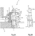
- 2A shows a sectional side view of a clothes dryer 11 in the region of attachment of a compressor 103 to a floor assembly 12th
- 2B 1 shows a bolt 13 for fastening the compressor 103 to the floor assembly 12 with a metal bushing 14 of the floor assembly 12.
- the bolt 13 also extends through the through hole 110 of the grommet 104 here.
- the Grommet 104 rests directly on a plastic region of the floor assembly 12.
- the metal bush 14 may optionally protrude into the through hole 110 of the grommet 104.
- the metal bushing 14 then also serves for the safer positioning of the grommet 104.
- the metal bushing 14 is equipped with an internal thread and embedded in a mounting portion 15 in the existing plastic bottom group 12, for example, injected, pressed, embedded with ultrasound and / or welded, etc.
- the bolt 13 is screwed into the metal bushing 14.
- the bolt 13 differs if necessary, only by the nature of its external thread 16 of the bolt 3.
- they can on the outside of the circular cylindrical shape reject, for example, by being not rotationally symmetrical, has longitudinal ribs, etc.
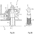
- 3A shows a sectional side view of a clothes dryer 21 in the region of attachment of a compressor 103 to a floor assembly 22 made of plastic.
- 3B shows a bolt 23 for fastening the compressor 103 to the floor assembly 22.
- the bolt 23 is pressed from below into a tubular or sleeve-shaped mounting region 24 of the bottom group 22.
- the bolt 23 has a flange on the foot side 25 as a stop against the bottom group 22. In order to lock the bolt 23 against rotation, this can be laterally circumferentially provided with notches 26 and so on.
- the bolt 23 may have a paragraph 8. On its side facing away from the bottom group 22, the bolt 23 also has an external thread 9 for screwing on a nut 108.
- 4A shows a sectional side view of a clothes dryer 31 in the region of attachment of a compressor 103 to a bottom group 32 made of plastic.
- 4B shows in a view obliquely from above a bolt 33 for attachment of the compressor 103 to the bottom group 32nd
- the bolt 33 has an external thread 34 at its front portion. He also has the rear of a screw head 35, so that can be dispensed with the self-contained nut 108.
- a shaft 38 of the bolt is slipped over an additional metal tube 36, by means of which the bolt 33 is supported on an edge of the mounting portion 37.
- a washer 107 is additionally provided between screw head 35 and metal tube 36.
- radial notches or the like can be used. (O. Fig.)
- the mounting portion 37 and / or the washer 107 may be provided to lock against rotation.
- FIG.5A shows a sectional side view of a clothes dryer 41 in the region of attachment of a compressor 103 to a bottom group 42 made of plastic.
- FIG.5B shows in a view obliquely from above a bolt 43 for attachment of the compressor 103 to the bottom group 42.
- the bolt has similar to the bolt 33 at its front portion an external thread 44 and at its other end a screw head 35.
- no metal pipe is now available.
- a tubular fastening region 45 of the base group 42, into which the bolt 43 can be screwed, is so far advanced that the washer 107 can be supported directly on an end edge of the fastening region 45.
- Figure 6 shows in a view obliquely from above a section of the bottom group 2 of the tumble dryer 1 in a provided for receiving the compressor 103 trough-like area.
- Figure 7 shows in a view obliquely from above another section of the bottom group 2 in the space provided for receiving the compressor 103 area.
- Figure 8 shows the intended for receiving the compressor 103 area of the floor assembly 2 fragmentary in a view obliquely from below.
- the three attachment regions 5 are introduced into shell-like structures or regions 51 of the floor assembly 2, which in turn transition into a rib-like, in particular honeycomb, structure 52.
- the attachment areas 5 are "flow-oriented" connected to the environment in order to absorb the forces that are introduced by the compressor 103 in the bottom group 2, effective in light construction.
- U-shaped or trapezoidal bead profiles can be used.
- the floor assembly 2 in particular on its shell-like regions 51 and / or on its rib-like structure 52, can be provided with a plastic material (also of another material, for example of glass fiber reinforced plastic).
- the plastic material may e.g. welded or glued.
- adhesives e.g. vibration-absorbing adhesives suitable.
- concrete and possibly reinforcement can be introduced into the floor assembly 2, in particular into its shell-like regions 51 and / or into its rib-like structure 52, for example for stiffening or even for replacement thereof. On can be realized as an improved insulation and vibration absorption.
- foam, styrofoam, potting compound, tar, etc. may be incorporated into the underbody 2, in particular into its shell-like regions 51 and / or into its rib-like structure 52, e.g. for a stiffener. On can be realized as an improved insulation and vibration absorption.
- a metal shell can also be used with the fourth and fifth embodiments.
- Fig.6 to 8 also be used with the second to fifth embodiments.
- a number may include exactly the specified number as well as a usual tolerance range, as long as this is not explicitly excluded.
Landscapes
- Engineering & Computer Science (AREA)
- Textile Engineering (AREA)
- General Engineering & Computer Science (AREA)
- Mechanical Engineering (AREA)
- Detail Structures Of Washing Machines And Dryers (AREA)
- Drying Of Solid Materials (AREA)
- Connection Of Plates (AREA)
Priority Applications (1)
| Application Number | Priority Date | Filing Date | Title |
|---|---|---|---|
| PL17163068T PL3235943T3 (pl) | 2016-04-19 | 2017-03-27 | Urządzenie do suszenia prania z pompą ciepła i przynależnym napędem |
Applications Claiming Priority (1)
| Application Number | Priority Date | Filing Date | Title |
|---|---|---|---|
| DE102016206525.4A DE102016206525A1 (de) | 2016-04-19 | 2016-04-19 | Wäschetrocknungsgerät mit Wärmepumpe und zugehörigem Antrieb |
Publications (2)
| Publication Number | Publication Date |
|---|---|
| EP3235943A1 true EP3235943A1 (fr) | 2017-10-25 |
| EP3235943B1 EP3235943B1 (fr) | 2019-02-27 |
Family
ID=58428190
Family Applications (1)
| Application Number | Title | Priority Date | Filing Date |
|---|---|---|---|
| EP17163068.4A Active EP3235943B1 (fr) | 2016-04-19 | 2017-03-27 | Sèche-linge comprenant une pompe à chaleur et entraînement associé |
Country Status (4)
| Country | Link |
|---|---|
| EP (1) | EP3235943B1 (fr) |
| CN (1) | CN107354696B (fr) |
| DE (1) | DE102016206525A1 (fr) |
| PL (1) | PL3235943T3 (fr) |
Cited By (2)
| Publication number | Priority date | Publication date | Assignee | Title |
|---|---|---|---|---|
| US10976063B2 (en) | 2019-02-19 | 2021-04-13 | Carrier Corporation | Vibration reducing grommet |
| EP4506628A1 (fr) * | 2023-08-10 | 2025-02-12 | LG Electronics Inc. | Unité extérieure pour système de climatisation |
Families Citing this family (4)
| Publication number | Priority date | Publication date | Assignee | Title |
|---|---|---|---|---|
| DE102017123316A1 (de) * | 2017-10-09 | 2018-11-15 | Miele & Cie. Kg | Stationäres Haushaltsgerät, vorzugsweise Wärmepumpenwäschetrockner |
| DE102018207641A1 (de) * | 2018-05-16 | 2019-11-21 | BSH Hausgeräte GmbH | Kompressorhalterung und Verfahren zur Montage einer Kompressorhalterung |
| CN110804841B (zh) * | 2018-08-06 | 2022-05-13 | 无锡小天鹅电器有限公司 | 支撑减振装置及具有其的洗衣机 |
| DE102022132806A1 (de) | 2022-12-09 | 2024-06-20 | Miele & Cie. Kg | Haltevorrichtung zum Halten einer Gerätetür für ein Reinigungsgerät, Reinigungsgerät sowie Verfahren zum Herstellen einer Haltevorrichtung |
Citations (10)
| Publication number | Priority date | Publication date | Assignee | Title |
|---|---|---|---|---|
| US6499714B1 (en) * | 2001-10-04 | 2002-12-31 | John R. Wike | System for and method of mounting compressors |
| JP2007143736A (ja) | 2005-11-25 | 2007-06-14 | Toshiba Corp | 衣類乾燥機 |
| JP2008088919A (ja) | 2006-10-03 | 2008-04-17 | Toshiba Corp | ヒートポンプ機構およびヒートポンプ機構を有するドラム式洗濯乾燥機 |
| JP2010057545A (ja) | 2008-09-01 | 2010-03-18 | Toshiba Corp | 洗濯乾燥機 |
| US20100107703A1 (en) * | 2005-07-26 | 2010-05-06 | Kabushiki Kaisha Toshiba | Drum-type washer/dryer |
| US20110154676A1 (en) | 2009-12-29 | 2011-06-30 | Electrolux Home Products Corporation N.V. | Home Laundry Drier with Releasably Securable Vibration Damper |
| EP2559804A1 (fr) | 2011-08-18 | 2013-02-20 | BSH Electrodomésticos España, S.A. | Appareil domestique comprenant une unité de commande pour pompe à chaleur |
| EP2743394A1 (fr) | 2012-12-14 | 2014-06-18 | Electrolux Home Products Corporation N.V. | Appareil de traitement de linge à pompe thermique |
| EP2743395A1 (fr) | 2012-12-14 | 2014-06-18 | Electrolux Home Products Corporation N.V. | Appareil de traitement de linge à pompe thermique |
| DE102013226398A1 (de) * | 2013-12-18 | 2015-06-18 | BSH Hausgeräte GmbH | Haushaltsgerät umfassend ein auf einer ebenen Basis angebrachtes Funktionsteil |
Family Cites Families (4)
| Publication number | Priority date | Publication date | Assignee | Title |
|---|---|---|---|---|
| KR100443568B1 (ko) * | 2002-08-19 | 2004-08-09 | 대영이앤비 주식회사 | 냉각장치의 압축기 고정장치 |
| JP2008000260A (ja) * | 2006-06-21 | 2008-01-10 | Toshiba Corp | ドラム式洗濯乾燥機 |
| CN102493161B (zh) * | 2011-10-19 | 2016-08-03 | 青岛海尔滚筒洗衣机有限公司 | 一种降低热泵模块振动噪音的固定安装结构 |
| CN204476726U (zh) * | 2015-02-04 | 2015-07-15 | 浙江博莱特制冷设备有限公司 | 一种制冷压缩机的电机侧机组减震装置 |
-
2016
- 2016-04-19 DE DE102016206525.4A patent/DE102016206525A1/de not_active Withdrawn
-
2017
- 2017-03-27 PL PL17163068T patent/PL3235943T3/pl unknown
- 2017-03-27 EP EP17163068.4A patent/EP3235943B1/fr active Active
- 2017-04-17 CN CN201710249316.8A patent/CN107354696B/zh active Active
Patent Citations (10)
| Publication number | Priority date | Publication date | Assignee | Title |
|---|---|---|---|---|
| US6499714B1 (en) * | 2001-10-04 | 2002-12-31 | John R. Wike | System for and method of mounting compressors |
| US20100107703A1 (en) * | 2005-07-26 | 2010-05-06 | Kabushiki Kaisha Toshiba | Drum-type washer/dryer |
| JP2007143736A (ja) | 2005-11-25 | 2007-06-14 | Toshiba Corp | 衣類乾燥機 |
| JP2008088919A (ja) | 2006-10-03 | 2008-04-17 | Toshiba Corp | ヒートポンプ機構およびヒートポンプ機構を有するドラム式洗濯乾燥機 |
| JP2010057545A (ja) | 2008-09-01 | 2010-03-18 | Toshiba Corp | 洗濯乾燥機 |
| US20110154676A1 (en) | 2009-12-29 | 2011-06-30 | Electrolux Home Products Corporation N.V. | Home Laundry Drier with Releasably Securable Vibration Damper |
| EP2559804A1 (fr) | 2011-08-18 | 2013-02-20 | BSH Electrodomésticos España, S.A. | Appareil domestique comprenant une unité de commande pour pompe à chaleur |
| EP2743394A1 (fr) | 2012-12-14 | 2014-06-18 | Electrolux Home Products Corporation N.V. | Appareil de traitement de linge à pompe thermique |
| EP2743395A1 (fr) | 2012-12-14 | 2014-06-18 | Electrolux Home Products Corporation N.V. | Appareil de traitement de linge à pompe thermique |
| DE102013226398A1 (de) * | 2013-12-18 | 2015-06-18 | BSH Hausgeräte GmbH | Haushaltsgerät umfassend ein auf einer ebenen Basis angebrachtes Funktionsteil |
Cited By (2)
| Publication number | Priority date | Publication date | Assignee | Title |
|---|---|---|---|---|
| US10976063B2 (en) | 2019-02-19 | 2021-04-13 | Carrier Corporation | Vibration reducing grommet |
| EP4506628A1 (fr) * | 2023-08-10 | 2025-02-12 | LG Electronics Inc. | Unité extérieure pour système de climatisation |
Also Published As
| Publication number | Publication date |
|---|---|
| CN107354696B (zh) | 2021-02-19 |
| DE102016206525A1 (de) | 2017-10-19 |
| CN107354696A (zh) | 2017-11-17 |
| EP3235943B1 (fr) | 2019-02-27 |
| PL3235943T3 (pl) | 2019-08-30 |
Similar Documents
| Publication | Publication Date | Title |
|---|---|---|
| EP3235943B1 (fr) | Sèche-linge comprenant une pompe à chaleur et entraînement associé | |
| DE102017000900B4 (de) | Befestigungsanordnung für ein Fahrzeug | |
| EP2532568B1 (fr) | Dispositif de fixation d'un composant, par exemple d'une rambarde, sur une carrosserie de véhicule | |
| DE202006012493U1 (de) | Befestigungseinrichtung mit Toleranzausgleich | |
| DE102007037242A1 (de) | Befestigungseinrichtung mit Toleranzausgleich | |
| EP3586018B1 (fr) | Dispositif de fixation et module de fixation | |
| DE102007048975A1 (de) | Schnellbefestigungseinrichtung | |
| EP2108545B1 (fr) | Agencement de fixation d'un profilé, notamment d'un profilé creux, sur un toit de véhicule | |
| DE69519673T2 (de) | Dämpfungsvorrichtung für kraftfahrzeugstabilisatoren und verfahren zu ihrer befestigung | |
| EP3851686B1 (fr) | Dispositif de fixation léger | |
| WO2009030677A1 (fr) | Lave-linge | |
| EP3133305B1 (fr) | Écrou cage | |
| DE20213362U1 (de) | Befestigungsanordnung für eine Heckleuchte | |
| DE112019001836B4 (de) | Montageplatte für Bock-, Lauf- und Lenkrollen | |
| DE3114283A1 (de) | "befestigungselement aus kunststoff, insbesondere zur loesbaren befestigung von flachen werkstuecken" | |
| EP1612432B1 (fr) | Dispositif de fixation pour habillage et méthode de fixation | |
| EP3586017B1 (fr) | Dispositif de fixation et module de fixation | |
| DE102023002927A1 (de) | Schraubenmutter zum selbstschneidenden Einschrauben in vorgebohrte Fahrzeug- und Flugzeugteile mit einseitigem Zugang | |
| DE102018201607A1 (de) | Luftfederbeinverbindung mit einer Kraftfahrzeugkarosserie | |
| DE102012112362C5 (de) | Ventil mit einer Befestigungseinrichtung | |
| EP1033449B1 (fr) | Support en porte-à-faux pour montant à fixer sur le cadre portant le plancher d'un balcon | |
| AT412334B (de) | Kraftstofftank für ein fahrzeug | |
| DE102015206419B4 (de) | Anordnung zur Befestigung eines Bauteils an einer Halterung | |
| DE102010043732A1 (de) | Befestigungs-Vorrichtung für einen Heizkörper | |
| DE29710312U1 (de) | Nivellierelement |
Legal Events
| Date | Code | Title | Description |
|---|---|---|---|
| PUAI | Public reference made under article 153(3) epc to a published international application that has entered the european phase |
Free format text: ORIGINAL CODE: 0009012 |
|
| STAA | Information on the status of an ep patent application or granted ep patent |
Free format text: STATUS: THE APPLICATION HAS BEEN PUBLISHED |
|
| AK | Designated contracting states |
Kind code of ref document: A1 Designated state(s): AL AT BE BG CH CY CZ DE DK EE ES FI FR GB GR HR HU IE IS IT LI LT LU LV MC MK MT NL NO PL PT RO RS SE SI SK SM TR |
|
| AX | Request for extension of the european patent |
Extension state: BA ME |
|
| STAA | Information on the status of an ep patent application or granted ep patent |
Free format text: STATUS: REQUEST FOR EXAMINATION WAS MADE |
|
| 17P | Request for examination filed |
Effective date: 20180425 |
|
| RBV | Designated contracting states (corrected) |
Designated state(s): AL AT BE BG CH CY CZ DE DK EE ES FI FR GB GR HR HU IE IS IT LI LT LU LV MC MK MT NL NO PL PT RO RS SE SI SK SM TR |
|
| GRAP | Despatch of communication of intention to grant a patent |
Free format text: ORIGINAL CODE: EPIDOSNIGR1 |
|
| STAA | Information on the status of an ep patent application or granted ep patent |
Free format text: STATUS: GRANT OF PATENT IS INTENDED |
|
| RIC1 | Information provided on ipc code assigned before grant |
Ipc: D06F 37/20 20060101ALN20180831BHEP Ipc: D06F 58/20 20060101AFI20180831BHEP |
|
| INTG | Intention to grant announced |
Effective date: 20181008 |
|
| GRAS | Grant fee paid |
Free format text: ORIGINAL CODE: EPIDOSNIGR3 |
|
| GRAA | (expected) grant |
Free format text: ORIGINAL CODE: 0009210 |
|
| STAA | Information on the status of an ep patent application or granted ep patent |
Free format text: STATUS: THE PATENT HAS BEEN GRANTED |
|
| AK | Designated contracting states |
Kind code of ref document: B1 Designated state(s): AL AT BE BG CH CY CZ DE DK EE ES FI FR GB GR HR HU IE IS IT LI LT LU LV MC MK MT NL NO PL PT RO RS SE SI SK SM TR |
|
| REG | Reference to a national code |
Ref country code: GB Ref legal event code: FG4D Free format text: NOT ENGLISH |
|
| REG | Reference to a national code |
Ref country code: CH Ref legal event code: EP |
|
| REG | Reference to a national code |
Ref country code: AT Ref legal event code: REF Ref document number: 1101498 Country of ref document: AT Kind code of ref document: T Effective date: 20190315 |
|
| REG | Reference to a national code |
Ref country code: IE Ref legal event code: FG4D Free format text: LANGUAGE OF EP DOCUMENT: GERMAN |
|
| REG | Reference to a national code |
Ref country code: DE Ref legal event code: R096 Ref document number: 502017000806 Country of ref document: DE |
|
| REG | Reference to a national code |
Ref country code: NL Ref legal event code: MP Effective date: 20190227 |
|
| REG | Reference to a national code |
Ref country code: LT Ref legal event code: MG4D |
|
| PG25 | Lapsed in a contracting state [announced via postgrant information from national office to epo] |
Ref country code: PT Free format text: LAPSE BECAUSE OF FAILURE TO SUBMIT A TRANSLATION OF THE DESCRIPTION OR TO PAY THE FEE WITHIN THE PRESCRIBED TIME-LIMIT Effective date: 20190627 Ref country code: SE Free format text: LAPSE BECAUSE OF FAILURE TO SUBMIT A TRANSLATION OF THE DESCRIPTION OR TO PAY THE FEE WITHIN THE PRESCRIBED TIME-LIMIT Effective date: 20190227 Ref country code: FI Free format text: LAPSE BECAUSE OF FAILURE TO SUBMIT A TRANSLATION OF THE DESCRIPTION OR TO PAY THE FEE WITHIN THE PRESCRIBED TIME-LIMIT Effective date: 20190227 Ref country code: NO Free format text: LAPSE BECAUSE OF FAILURE TO SUBMIT A TRANSLATION OF THE DESCRIPTION OR TO PAY THE FEE WITHIN THE PRESCRIBED TIME-LIMIT Effective date: 20190527 Ref country code: LT Free format text: LAPSE BECAUSE OF FAILURE TO SUBMIT A TRANSLATION OF THE DESCRIPTION OR TO PAY THE FEE WITHIN THE PRESCRIBED TIME-LIMIT Effective date: 20190227 Ref country code: NL Free format text: LAPSE BECAUSE OF FAILURE TO SUBMIT A TRANSLATION OF THE DESCRIPTION OR TO PAY THE FEE WITHIN THE PRESCRIBED TIME-LIMIT Effective date: 20190227 |
|
| PG25 | Lapsed in a contracting state [announced via postgrant information from national office to epo] |
Ref country code: BG Free format text: LAPSE BECAUSE OF FAILURE TO SUBMIT A TRANSLATION OF THE DESCRIPTION OR TO PAY THE FEE WITHIN THE PRESCRIBED TIME-LIMIT Effective date: 20190527 Ref country code: IS Free format text: LAPSE BECAUSE OF FAILURE TO SUBMIT A TRANSLATION OF THE DESCRIPTION OR TO PAY THE FEE WITHIN THE PRESCRIBED TIME-LIMIT Effective date: 20190627 Ref country code: GR Free format text: LAPSE BECAUSE OF FAILURE TO SUBMIT A TRANSLATION OF THE DESCRIPTION OR TO PAY THE FEE WITHIN THE PRESCRIBED TIME-LIMIT Effective date: 20190528 Ref country code: LV Free format text: LAPSE BECAUSE OF FAILURE TO SUBMIT A TRANSLATION OF THE DESCRIPTION OR TO PAY THE FEE WITHIN THE PRESCRIBED TIME-LIMIT Effective date: 20190227 Ref country code: HR Free format text: LAPSE BECAUSE OF FAILURE TO SUBMIT A TRANSLATION OF THE DESCRIPTION OR TO PAY THE FEE WITHIN THE PRESCRIBED TIME-LIMIT Effective date: 20190227 Ref country code: RS Free format text: LAPSE BECAUSE OF FAILURE TO SUBMIT A TRANSLATION OF THE DESCRIPTION OR TO PAY THE FEE WITHIN THE PRESCRIBED TIME-LIMIT Effective date: 20190227 |
|
| PG25 | Lapsed in a contracting state [announced via postgrant information from national office to epo] |
Ref country code: SK Free format text: LAPSE BECAUSE OF FAILURE TO SUBMIT A TRANSLATION OF THE DESCRIPTION OR TO PAY THE FEE WITHIN THE PRESCRIBED TIME-LIMIT Effective date: 20190227 Ref country code: RO Free format text: LAPSE BECAUSE OF FAILURE TO SUBMIT A TRANSLATION OF THE DESCRIPTION OR TO PAY THE FEE WITHIN THE PRESCRIBED TIME-LIMIT Effective date: 20190227 Ref country code: CZ Free format text: LAPSE BECAUSE OF FAILURE TO SUBMIT A TRANSLATION OF THE DESCRIPTION OR TO PAY THE FEE WITHIN THE PRESCRIBED TIME-LIMIT Effective date: 20190227 Ref country code: EE Free format text: LAPSE BECAUSE OF FAILURE TO SUBMIT A TRANSLATION OF THE DESCRIPTION OR TO PAY THE FEE WITHIN THE PRESCRIBED TIME-LIMIT Effective date: 20190227 Ref country code: IT Free format text: LAPSE BECAUSE OF FAILURE TO SUBMIT A TRANSLATION OF THE DESCRIPTION OR TO PAY THE FEE WITHIN THE PRESCRIBED TIME-LIMIT Effective date: 20190227 Ref country code: DK Free format text: LAPSE BECAUSE OF FAILURE TO SUBMIT A TRANSLATION OF THE DESCRIPTION OR TO PAY THE FEE WITHIN THE PRESCRIBED TIME-LIMIT Effective date: 20190227 Ref country code: ES Free format text: LAPSE BECAUSE OF FAILURE TO SUBMIT A TRANSLATION OF THE DESCRIPTION OR TO PAY THE FEE WITHIN THE PRESCRIBED TIME-LIMIT Effective date: 20190227 Ref country code: AL Free format text: LAPSE BECAUSE OF FAILURE TO SUBMIT A TRANSLATION OF THE DESCRIPTION OR TO PAY THE FEE WITHIN THE PRESCRIBED TIME-LIMIT Effective date: 20190227 |
|
| REG | Reference to a national code |
Ref country code: DE Ref legal event code: R097 Ref document number: 502017000806 Country of ref document: DE |
|
| PG25 | Lapsed in a contracting state [announced via postgrant information from national office to epo] |
Ref country code: LU Free format text: LAPSE BECAUSE OF NON-PAYMENT OF DUE FEES Effective date: 20190327 Ref country code: SM Free format text: LAPSE BECAUSE OF FAILURE TO SUBMIT A TRANSLATION OF THE DESCRIPTION OR TO PAY THE FEE WITHIN THE PRESCRIBED TIME-LIMIT Effective date: 20190227 |
|
| REG | Reference to a national code |
Ref country code: BE Ref legal event code: MM Effective date: 20190331 |
|
| PG25 | Lapsed in a contracting state [announced via postgrant information from national office to epo] |
Ref country code: MC Free format text: LAPSE BECAUSE OF FAILURE TO SUBMIT A TRANSLATION OF THE DESCRIPTION OR TO PAY THE FEE WITHIN THE PRESCRIBED TIME-LIMIT Effective date: 20190227 |
|
| PLBE | No opposition filed within time limit |
Free format text: ORIGINAL CODE: 0009261 |
|
| STAA | Information on the status of an ep patent application or granted ep patent |
Free format text: STATUS: NO OPPOSITION FILED WITHIN TIME LIMIT |
|
| PG25 | Lapsed in a contracting state [announced via postgrant information from national office to epo] |
Ref country code: IE Free format text: LAPSE BECAUSE OF NON-PAYMENT OF DUE FEES Effective date: 20190327 |
|
| 26N | No opposition filed |
Effective date: 20191128 |
|
| PG25 | Lapsed in a contracting state [announced via postgrant information from national office to epo] |
Ref country code: SI Free format text: LAPSE BECAUSE OF FAILURE TO SUBMIT A TRANSLATION OF THE DESCRIPTION OR TO PAY THE FEE WITHIN THE PRESCRIBED TIME-LIMIT Effective date: 20190227 Ref country code: BE Free format text: LAPSE BECAUSE OF NON-PAYMENT OF DUE FEES Effective date: 20190331 Ref country code: FR Free format text: LAPSE BECAUSE OF NON-PAYMENT OF DUE FEES Effective date: 20190427 |
|
| PG25 | Lapsed in a contracting state [announced via postgrant information from national office to epo] |
Ref country code: TR Free format text: LAPSE BECAUSE OF FAILURE TO SUBMIT A TRANSLATION OF THE DESCRIPTION OR TO PAY THE FEE WITHIN THE PRESCRIBED TIME-LIMIT Effective date: 20190227 |
|
| PG25 | Lapsed in a contracting state [announced via postgrant information from national office to epo] |
Ref country code: MT Free format text: LAPSE BECAUSE OF FAILURE TO SUBMIT A TRANSLATION OF THE DESCRIPTION OR TO PAY THE FEE WITHIN THE PRESCRIBED TIME-LIMIT Effective date: 20190227 |
|
| REG | Reference to a national code |
Ref country code: CH Ref legal event code: PL |
|
| PG25 | Lapsed in a contracting state [announced via postgrant information from national office to epo] |
Ref country code: CH Free format text: LAPSE BECAUSE OF NON-PAYMENT OF DUE FEES Effective date: 20200331 Ref country code: LI Free format text: LAPSE BECAUSE OF NON-PAYMENT OF DUE FEES Effective date: 20200331 |
|
| PG25 | Lapsed in a contracting state [announced via postgrant information from national office to epo] |
Ref country code: CY Free format text: LAPSE BECAUSE OF FAILURE TO SUBMIT A TRANSLATION OF THE DESCRIPTION OR TO PAY THE FEE WITHIN THE PRESCRIBED TIME-LIMIT Effective date: 20190227 |
|
| PG25 | Lapsed in a contracting state [announced via postgrant information from national office to epo] |
Ref country code: HU Free format text: LAPSE BECAUSE OF FAILURE TO SUBMIT A TRANSLATION OF THE DESCRIPTION OR TO PAY THE FEE WITHIN THE PRESCRIBED TIME-LIMIT; INVALID AB INITIO Effective date: 20170327 |
|
| PG25 | Lapsed in a contracting state [announced via postgrant information from national office to epo] |
Ref country code: MK Free format text: LAPSE BECAUSE OF FAILURE TO SUBMIT A TRANSLATION OF THE DESCRIPTION OR TO PAY THE FEE WITHIN THE PRESCRIBED TIME-LIMIT Effective date: 20190227 |
|
| REG | Reference to a national code |
Ref country code: DE Ref legal event code: R084 Ref document number: 502017000806 Country of ref document: DE |
|
| REG | Reference to a national code |
Ref country code: AT Ref legal event code: MM01 Ref document number: 1101498 Country of ref document: AT Kind code of ref document: T Effective date: 20220327 |
|
| PGFP | Annual fee paid to national office [announced via postgrant information from national office to epo] |
Ref country code: GB Payment date: 20230323 Year of fee payment: 7 |
|
| PG25 | Lapsed in a contracting state [announced via postgrant information from national office to epo] |
Ref country code: AT Free format text: LAPSE BECAUSE OF NON-PAYMENT OF DUE FEES Effective date: 20220327 |
|
| PGFP | Annual fee paid to national office [announced via postgrant information from national office to epo] |
Ref country code: PL Payment date: 20240318 Year of fee payment: 8 |
|
| GBPC | Gb: european patent ceased through non-payment of renewal fee |
Effective date: 20240327 |
|
| PG25 | Lapsed in a contracting state [announced via postgrant information from national office to epo] |
Ref country code: GB Free format text: LAPSE BECAUSE OF NON-PAYMENT OF DUE FEES Effective date: 20240327 |
|
| PG25 | Lapsed in a contracting state [announced via postgrant information from national office to epo] |
Ref country code: GB Free format text: LAPSE BECAUSE OF NON-PAYMENT OF DUE FEES Effective date: 20240327 |
|
| PGFP | Annual fee paid to national office [announced via postgrant information from national office to epo] |
Ref country code: DE Payment date: 20260331 Year of fee payment: 10 |