EP3235965A1 - Système et procédé pour la construction préfabriquée avec des noeuds structuraux tridimensionnels - Google Patents
Système et procédé pour la construction préfabriquée avec des noeuds structuraux tridimensionnels Download PDFInfo
- Publication number
- EP3235965A1 EP3235965A1 EP15828818.3A EP15828818A EP3235965A1 EP 3235965 A1 EP3235965 A1 EP 3235965A1 EP 15828818 A EP15828818 A EP 15828818A EP 3235965 A1 EP3235965 A1 EP 3235965A1
- Authority
- EP
- European Patent Office
- Prior art keywords
- boards
- structural element
- structural
- slots
- groups
- Prior art date
- Legal status (The legal status is an assumption and is not a legal conclusion. Google has not performed a legal analysis and makes no representation as to the accuracy of the status listed.)
- Granted
Links
Images

Classifications
-
- E—FIXED CONSTRUCTIONS
- E04—BUILDING
- E04B—GENERAL BUILDING CONSTRUCTIONS; WALLS, e.g. PARTITIONS; ROOFS; FLOORS; CEILINGS; INSULATION OR OTHER PROTECTION OF BUILDINGS
- E04B1/00—Constructions in general; Structures which are not restricted either to walls, e.g. partitions, or floors or ceilings or roofs
- E04B1/18—Structures comprising elongated load-supporting parts, e.g. columns, girders, skeletons
- E04B1/26—Structures comprising elongated load-supporting parts, e.g. columns, girders, skeletons the supporting parts consisting of wood
- E04B1/2604—Connections specially adapted therefor
-
- E—FIXED CONSTRUCTIONS
- E04—BUILDING
- E04B—GENERAL BUILDING CONSTRUCTIONS; WALLS, e.g. PARTITIONS; ROOFS; FLOORS; CEILINGS; INSULATION OR OTHER PROTECTION OF BUILDINGS
- E04B1/00—Constructions in general; Structures which are not restricted either to walls, e.g. partitions, or floors or ceilings or roofs
- E04B1/18—Structures comprising elongated load-supporting parts, e.g. columns, girders, skeletons
- E04B1/19—Three-dimensional [3D] framework structures
- E04B2001/1975—Frameworks where the struts are directly connected to each other, i.e. without interposed connecting nodes or plates
-
- E—FIXED CONSTRUCTIONS
- E04—BUILDING
- E04B—GENERAL BUILDING CONSTRUCTIONS; WALLS, e.g. PARTITIONS; ROOFS; FLOORS; CEILINGS; INSULATION OR OTHER PROTECTION OF BUILDINGS
- E04B1/00—Constructions in general; Structures which are not restricted either to walls, e.g. partitions, or floors or ceilings or roofs
- E04B1/18—Structures comprising elongated load-supporting parts, e.g. columns, girders, skeletons
- E04B1/19—Three-dimensional [3D] framework structures
- E04B2001/1993—Details of framework supporting structure, e.g. posts or walls
-
- E—FIXED CONSTRUCTIONS
- E04—BUILDING
- E04B—GENERAL BUILDING CONSTRUCTIONS; WALLS, e.g. PARTITIONS; ROOFS; FLOORS; CEILINGS; INSULATION OR OTHER PROTECTION OF BUILDINGS
- E04B1/00—Constructions in general; Structures which are not restricted either to walls, e.g. partitions, or floors or ceilings or roofs
- E04B1/18—Structures comprising elongated load-supporting parts, e.g. columns, girders, skeletons
- E04B1/26—Structures comprising elongated load-supporting parts, e.g. columns, girders, skeletons the supporting parts consisting of wood
- E04B1/2604—Connections specially adapted therefor
- E04B2001/262—Connection node with interlocking of specially shaped wooden members, e.g. puzzle type connection
-
- E—FIXED CONSTRUCTIONS
- E04—BUILDING
- E04B—GENERAL BUILDING CONSTRUCTIONS; WALLS, e.g. PARTITIONS; ROOFS; FLOORS; CEILINGS; INSULATION OR OTHER PROTECTION OF BUILDINGS
- E04B1/00—Constructions in general; Structures which are not restricted either to walls, e.g. partitions, or floors or ceilings or roofs
- E04B1/18—Structures comprising elongated load-supporting parts, e.g. columns, girders, skeletons
- E04B1/26—Structures comprising elongated load-supporting parts, e.g. columns, girders, skeletons the supporting parts consisting of wood
- E04B1/2604—Connections specially adapted therefor
- E04B2001/2672—Connections specially adapted therefor for members formed from a number of parallel sections
-
- E—FIXED CONSTRUCTIONS
- E04—BUILDING
- E04B—GENERAL BUILDING CONSTRUCTIONS; WALLS, e.g. PARTITIONS; ROOFS; FLOORS; CEILINGS; INSULATION OR OTHER PROTECTION OF BUILDINGS
- E04B1/00—Constructions in general; Structures which are not restricted either to walls, e.g. partitions, or floors or ceilings or roofs
- E04B1/18—Structures comprising elongated load-supporting parts, e.g. columns, girders, skeletons
- E04B1/26—Structures comprising elongated load-supporting parts, e.g. columns, girders, skeletons the supporting parts consisting of wood
- E04B1/2604—Connections specially adapted therefor
- E04B2001/2676—Connector nodes
-
- E—FIXED CONSTRUCTIONS
- E04—BUILDING
- E04B—GENERAL BUILDING CONSTRUCTIONS; WALLS, e.g. PARTITIONS; ROOFS; FLOORS; CEILINGS; INSULATION OR OTHER PROTECTION OF BUILDINGS
- E04B2103/00—Material constitution of slabs, sheets or the like
- E04B2103/04—Material constitution of slabs, sheets or the like of plastics, fibrous material or wood
Definitions
- the present invention relates to a prefabricated construction system and method with three-dimensional structural nodes, for erecting constructions by means of the assembly of prefabricated structural elements obtained by cutting flat materials, such as, for example, boards or planks of wood or of a product derived from wood.
- Patent document US5185982 describes the attachment of three boards, each provided with a slot at the head thereof, by means of mutual interaction and coupling, forming a three-dimensional node, but in this case one of the elements arranged horizontally must be placed with the main faces thereof having a larger surface parallel to the ground, thereby providing very low inertia and therefore little structural resistance.
- patent documents US3966337 and US5813737 which refer to furniture and not construction systems for buildings, with all the differences this entails, show the mutual attachment of two boards, arranged horizontally and with the main faces thereof having a larger surface in the vertical direction, thereby providing greater structural resistance, said attachment being obtained by means of respective mutually coupleable slots.
- the attachment of said two boards can in turn be coupled to a vertical element, in turn provided with slots, recesses and gaps between struts.
- This configuration is far from being like the proposed configuration, since the lower resistance requirements of furniture allow the configuration proposed by these patent documents to be sufficient, but this configuration cannot be taken literally to the building construction site because the structural resistance requirements are much greater.
- each of the structural elements is made up of a plurality of boards arranged parallel to one another, thereby increasing the resistance thereof, but making the anchoring of said plurality of elements somewhat more complicated and the solution to this problem is not obvious in view of the mentioned prior art documents.
- the present invention relates to a prefabricated construction system with three-dimensional structural nodes.
- the described construction system consists of a set of elements that can be manufactured in a factory or workshop, in the amount, shape and number suitable for the construction to be performed, previously designed by means of a construction project.
- Said elements will be produced preferably from wood, or from products derived from wood, such as, for example, plywood, agglomerated wood, resins, resins and paper, although other materials such as plastics or metals are also acceptable. These materials are resistant, easy to cut, lightweight and have other qualities, such as being recyclable; they are therefore optimal materials for this use.
- prefabricated elements are then transported to the construction site, where they are assembled for erecting a self-supporting structure, by means of the formation of three-dimensional structural nodes formed by the attachment of at least two structural elements.
- the obtained structure can subsequently be covered by means of enclosure panels, likewise prefabricated and forming part of the construction system, thereby obtaining the projected construction in a completely prefabricated manner by means of standardized dry construction techniques.
- the first and second structural elements will act as girders, as tie beams, as cross members, or as other structural elements, according to their location in the set of the structure, their position being able to be horizontal, or with a certain inclination in the event of being part of the structure of a pitched roof, or of a stairway or ramp.
- the first structural element is not parallel with respect to the second structural element, preferably being perpendicular and each structural element will be provided with at least one coupling configuration, the first and second coupling configurations being complementary to one another, being able to be mutually attached by fixing the relative position of the first and second structural element.
- the first coupling configuration will be located in the lower half of the first structural element, and the second coupling configuration will be located in the upper half of the second structural element, but the reverse configuration in which the coupling configuration of the first structural element is located in the upper half, whereas the second coupling configuration is located in the lower half of the second structural element, is also acceptable.
- the proposed invention differs from the known techniques by also including the following distinctive features:
- each structural element is actually an element made up of a plurality of boards arranged with the larger faces thereof in the vertical direction. This position of each board is what provides greater inertia, and therefore greater structural resistance.
- Both the boards forming a structural element and the boards forming a group of boards can be attached to one another, or they may not be attached to one another, their relative position being fixed by the three-dimensional structural nodes.
- the coupling of the first structural element and the second structural element forms a structural node in the form of an array leaving free interstitial openings.
- Said interstitial openings can serve for the connection of additional structural elements, as will be described below, or to allow passage through said structural core of installation ducts, such as, for example, ducts for wiring or plumbing, when said additional structural elements do not exist.
- the first and second coupling configurations are each formed by a plurality of slots made in the corresponding structural elements. Since each structural element is formed by a plurality of boards, each slot covers all the boards forming said structural element, each board having a portion of the slot such that, when all the boards are placed in their mounting position, the slot portions are aligned and form the slot.
- the high degree of precision required in the board cutting operations to achieve the correct alignment of said slot portions make it advisable to use cutting and automatic or robotized routing techniques, as described below.
- the angle formed by the slots of the first and second structural elements with respect to the front faces thereof will be identical, and equal to the existing angle, in the mounting position, between the first and second structural elements, because it is the fitting between the first and second anchoring configuration that defines the angle between the first and second structural elements.
- the angle formed by the slots of the first structural element with respect to the side faces thereof will be equal to the angle of inclination of said first structural element with respect to the vertical in the mounting position. The same occurs between the slots of the second anchoring configuration and the second structural element.
- Projections are defined between the slots of one and the same coupling configuration, which projections are the material remaining between two spaced slots.
- the tight insertion of said first slots of the first structural element in the second slots of the second structural element produces an attachment between both elements, and at least a partial intersection thereof, achieving a very rigid node.
- Said interstitial openings will have, in the mounting position, a vertical direction, and a quadrangular section, which will be square if the first and second structural elements are perpendicular, and rhombus-shaped if they are not.
- the first and second structural elements can have the corresponding first and second coupling configurations at the ends thereof, or have them in an intermediate position, said structural elements then being elements passing therethrough, having a portion on each side of the structural node.
- the first and second coupling configurations preferably have at least one of the following features, and preferably all of them:
- the construction system can also include a third structural vertical element, performing the functions of column, strut, as an element forming part of a structural wall, or of other structural vertical elements, according to their location in the set of the structure. Said third structural element will also be attached to the mentioned structural node.
- the third structural element is also formed by a plurality of boards or of groups of boards spaced from one another and has third slots made at the head thereof, leaving therebetween third projections having a size equal to or less than said interstitial openings.
- This configuration allows the third projections of each board or group of boards forming the third coupling configuration to be inserted into the interstitial openings, the third structural element thereby being attached to the first and second structural elements, forming the three-dimensional structural node.
- the shape and size of said third projections must be complementary to the shape and size of said interstitial openings.
- the third coupling configuration of the third structural element has at least one of the following features:
- a system that simultaneously has all these features and the previously mentioned features would provide a structural node which, in the mounting position, has no hollow spaces or clearances therein, and would therefore also provide a rigid attachment between its elements, preventing any movement or play between its parts.
- the construction system can include a fourth structural element with features identical to those of the third structural element, being provided with fourth slots and fourth projections, said fourth structural element being able to be inserted into the mentioned interstitial openings of the structural node from a face opposite the face of insertion of the third structural element, the third and fourth structural elements then facing one another at their respective heads and aligned, and their respective boards or groups of boards being vertically aligned or misaligned.
- This fourth structural element allows making structures several stories high, as well as suspended floors and lofts.
- the fourth coupling configuration will preferably include at least one of the following features:
- first and second structural elements can each have one or several coupling configurations both at the ends thereof and in intermediate positions, and that the third structural element can have coupling configurations in one or both of the ends thereof.
- first and second structural elements will be, in the coupling position, flush along the upper face thereof, thereby providing a support plane on which the ground is installed.
- the boards or groups of boards of the third and optionally of the fourth structural element are inserted into the separation spaces existing between the boards or groups of boards of the first or second structural element.
- said third and fourth structural element should be made up of a number of boards or of groups of boards equal to the number of boards and/or groups of boards forming the first or second structural element plus one or minus one, thus being the structural node symmetrical.
- the first or second structural elements has a plurality of straight notches arranged in a side face of the boards, said notches being made in a side face opposite the side face containing the mentioned first or second projections and vertically aligned with said first and second projections, or made at the ends of the first or second projections of the first or second structural element, said notches being complementary to the third slots or fourth slots.
- These notches allow being coupled to the third slots, thus improving the attachment of the third structural element to the rest of the structural node.
- the mentioned notches can also include at least one of the following features:
- an automated and robotized manufacture of said boards by means of a cutting system with numerical control, controlled by a computer system which has been provided with all the dimensions of all the unitary elements making up the structural system is preferably required.
- the automated cutting system can obtain the necessary boards, each with its coupling configurations, from planks or sheets of raw material, from which all the boards are cut out.
- the automated cutting system can also engrave information on the surface of the boards in reference to their position in the structure, the order of the mounting thereof, the boards with which they are to be attached, or even cuts, guide holes can be made or information engraved in reference to other non-structural elements forming part of a construction, such as electrical ducts, switches, sockets, railings, doors, windows, etc.
- the present structural system also has aspects that are not known in the prior art in the manufacturing process thereof because even though the following steps of the process are already known:
- the automated cutting system includes, during cutting tasks of each board, information in reference to the position and/or placement thereof, and/or information in reference to the position and/or placement of other construction elements with respect to said board.
- the proposed construction method is characterized in that the computer model decides on the order of cutting the parts depending on at least one of the following variables:
- fixation systems can be used for assuring the attachment of the elements, these systems being able to be, for example, one of the following: screw, self-tapping screw, rivet, bolt, nail, adhesive, pin, etc.
- references to geometric position such as, for example, parallel, perpendicular, tangent, etc., allow deviations of up to ⁇ 5° with respect to the theoretical position defined by said nomenclature.
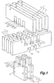
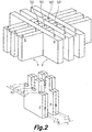
- a structural node is formed by the mutual coupling of a first structural element 1, a second structural element 2, a third structural element 3 and a fourth structural element 4.
- the first structural element 1 and the second structural element 2 are each made up of three boards 7 parallel to and spaced from one another, all of them arranged with their main faces 6 in the vertical direction.
- the third structural element 3 and the fourth structural element 4 are each made up of two groups of boards 5 parallel to and spaced from one another, each group of boards 5 in turn being formed by two boards 7 arranged with their main faces 6 in contact with one another.
- the groups of boards are likewise arranged with their main faces 6 in the vertical direction.
- the first structural element 1 has a first coupling configuration 10 formed by three first straight slots 11 made in each of the boards 7 forming said first structural element 1 from the their upper side faces 8 to half the width of their main faces 6, the first slots 11 of each board 7 facing and being aligned with the first slots 11 of the other boards 7 forming said first structural element 1.
- a first projection 12 is defined between each of said first slots 11, the three first slots 11 defining two first projections 12.
- the second structural element 2 has a second coupling configuration 20 formed by three second straight slots 21 made in each of the boards 7 forming said second structural element 2, from the lower side faces 8 thereof to half the width of the main faces 6 thereof, the second slots 21 of each board 7 facing and being aligned with the second slots 21 of the other boards 7 forming said second structural element 2.
- a second projection 22 is defined between each of said second slots 21, the three second slots 21 defining two second projections 22.
- the first coupling configuration 10 is complementary to the second coupling configuration 20, the width of the first slots 11 being equal to the width of the boards 7 forming the second structural element 2, and the width of the second slots 21 being equal to the width of the boards 7 forming the first structural element 1.
- the width of the first projections 12 define the separation distance between the boards 7 of the second structural element 2, and the width of the second projections 22 define the separation between the boards 7 of the first structural element 1.
- said interstitial openings 50 are square since the first and second structural elements 1 and 2 are perpendicular, but in another embodiment it is acceptable that both structural elements form with one another an angle other than 90°, creating rhombus-shaped interstitial openings 50 by means of the mutual coupling of first and second slots 11 and 21 going through the thickness of the boards 7 of the first and second structural elements 1 and 2 at said angle other than 90°, said slots therefore not being perpendicular to the main faces 6 of said boards 7.
- both the first and second structural elements 1 and 2 are horizontal, but in alternative embodiments it is contemplated that the first and/or the second structural element 1 and/or 2 form an angle with respect to the horizontal. In such case, the first or second slots 11 or 21 of the first or second structural elements 1 or 2 which are inclined will not be perpendicular to the side faces 8 of the boards 7 of the corresponding structural element.
- the third structural element 3 shown in Figures 1 and 2 has a third coupling configuration 30 formed by three third straight slots 31 made in each of the boards 7 of the groups of boards 5 forming said third structural element 3 from the upper head faces to a depth of half the width of the main face 6 of the first structural element 1, the third slots 31 of each board 7 facing and being aligned with the third slots 31 of the other boards 7 forming said third structural element 3.
- a third projection 32 is defined between each of said third slots 31, the three third slots 31 defining two third projections 32, and said third projections 32 having a size and shape complementary to those of the interstitial openings 50 to allow a tight fitting.
- the fourth structural element 4 has a fourth coupling configuration 40 formed by three fourth straight slots 41 made in each of the boards 7 of the groups of boards 5 forming said fourth structural element 4 from the lower head faces thereof to a depth of half the width of the main face 6 of the first structural element 1, the fourth slots 41 of each board 7 facing and being aligned with the fourth slots 41 of the other boards 7 forming said fourth structural element 4.
- a fourth projection 42 is defined between each of said fourth slots 41, the three fourth slots 41 defining two fourth projections 42, and said fourth projections 42 having a size and shape complementary to those of the interstitial openings 50 to allow a tight fitting.
- the third and fourth coupling configurations 30 and 40 are complementary to the array formed by the coupling of the first and second coupling configurations 10 and 20.
- the third projections 32 are inserted into the interstitial openings 50 from the lower face thereof and to a depth equal to half the width of the main faces 6 of the first structural element 1, an upper half of said interstitial openings 50 being empty to receive the fourth projections 42 of the fourth structural element 4.
- the fourth structural element 4 does not exist, the third projections 32 being longer, and the third structural element 3 being able to be inserted from both above and from below the interstitial openings 50.
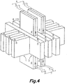
- the proposed three-dimensional structural nodes allow obtaining a rigid attachment of up to four structural elements, the first and second structural elements 1 and 2 being able to be elements passing through said structural node, such that it allows receiving elements from six different sides, like in the example shown in Figure 4 .
- Figure 1 attached hereto shows notches 60 made in the boards 7 of the first structural element 1, said notches 60 being made on the lower side face 8, opposite the upper side face 8 in which the first slots 31 have been made, and said slots 60 being aligned and facing the first projections 12. Said notches 60 allow partial insertion of the third structural element 3, which assures a more resistant structural attachment.
- the distal ends of the first projections 12 can be cut out, being removed with respect to the side face 8, which also works as a notch 60, allowing partial insertion of the fourth structural element 4.
Landscapes
- Engineering & Computer Science (AREA)
- Architecture (AREA)
- Physics & Mathematics (AREA)
- Electromagnetism (AREA)
- Civil Engineering (AREA)
- Structural Engineering (AREA)
- Joining Of Building Structures In Genera (AREA)
Applications Claiming Priority (2)
| Application Number | Priority Date | Filing Date | Title |
|---|---|---|---|
| ES201431842A ES2574330B1 (es) | 2014-12-16 | 2014-12-16 | Sistema y método constructivo prefabricado con nudos estructurales tridimensionales |
| PCT/ES2015/070918 WO2016097452A1 (fr) | 2014-12-16 | 2015-12-16 | Système et procédé pour la construction préfabriquée avec des noeuds structuraux tridimensionnels |
Publications (2)
| Publication Number | Publication Date |
|---|---|
| EP3235965A1 true EP3235965A1 (fr) | 2017-10-25 |
| EP3235965B1 EP3235965B1 (fr) | 2019-06-19 |
Family
ID=55262822
Family Applications (1)
| Application Number | Title | Priority Date | Filing Date |
|---|---|---|---|
| EP15828818.3A Not-in-force EP3235965B1 (fr) | 2014-12-16 | 2015-12-16 | Système et procédé pour la construction préfabriquée avec des noeuds structuraux tridimensionnels |
Country Status (5)
| Country | Link |
|---|---|
| US (1) | US10174497B2 (fr) |
| EP (1) | EP3235965B1 (fr) |
| AR (1) | AR103050A1 (fr) |
| ES (1) | ES2574330B1 (fr) |
| WO (1) | WO2016097452A1 (fr) |
Families Citing this family (7)
| Publication number | Priority date | Publication date | Assignee | Title |
|---|---|---|---|---|
| JP6454446B2 (ja) * | 2016-11-30 | 2019-01-23 | 株式会社飯田産業 | 建築物およびその建築工法 |
| CA2999557A1 (fr) * | 2017-03-27 | 2018-09-27 | Maurice Viens | Systeme de structure de murs |
| IT201700045810A1 (it) * | 2017-04-28 | 2017-07-28 | Leapfactory S R L | Sistema costruttivo per telai strutturali di edifici |
| FR3104927B1 (fr) * | 2019-12-20 | 2021-12-03 | Alain Chennaux | Meuble modulaire et évolutif |
| EP3919698B1 (fr) * | 2020-06-05 | 2023-08-02 | Phylem Structures, Sl | Système structural en bois modifié |
| US20240279917A1 (en) * | 2023-02-17 | 2024-08-22 | Peter Sing | Composite Stiffener |
| CN222835074U (zh) * | 2024-04-30 | 2025-05-06 | 浙江爱升婴童用品股份有限公司 | 一种组装式房屋 |
Family Cites Families (23)
| Publication number | Priority date | Publication date | Assignee | Title |
|---|---|---|---|---|
| FR413672A (fr) * | 1909-03-19 | 1910-08-16 | Paul Meltzer | Système de construction en bois |
| US1066212A (en) * | 1910-03-16 | 1913-07-01 | Paul Meltzer | Wood structure. |
| US1225760A (en) * | 1916-06-27 | 1917-05-15 | Oscar W Brown | Puzzle. |
| US1425107A (en) * | 1921-03-30 | 1922-08-08 | Levinson David | Toy |
| US1763748A (en) * | 1928-10-10 | 1930-06-17 | John H Best & Sons | Joint for costumers and other articles |
| US2712199A (en) * | 1952-10-06 | 1955-07-05 | Henry R Latimer | Toy building blocks |
| US3387868A (en) * | 1965-07-30 | 1968-06-11 | John C. Borden | Multiple member joining arrangement |
| US3779657A (en) * | 1971-04-21 | 1973-12-18 | Omniversal Design | Structural joint |
| FR2219674A7 (fr) | 1973-02-28 | 1974-09-20 | Bordes Bernard | |
| US3866371A (en) * | 1973-03-07 | 1975-02-18 | Midwest Housing Research Corp | Structural framing system |
| US3966337A (en) * | 1975-04-18 | 1976-06-29 | Elsie Crawford | Modular post and beam joint |
| FR2324258A1 (fr) * | 1975-09-18 | 1977-04-15 | Govin Bernard | Armature de meuble |
| SE414519B (sv) * | 1979-07-30 | 1980-08-04 | Erik Erland Eriksson | Anordning vid veggelement for att bilda hornfogar |
| CA1178775A (fr) * | 1982-09-28 | 1984-12-04 | Luc Trudeau | Joint demontable |
| US4540308A (en) * | 1983-12-27 | 1985-09-10 | Edward Colby | Joint for furniture support structure |
| US5185982A (en) | 1991-09-23 | 1993-02-16 | Stark Forest Products Inc. | Corner joint for modular assemblies |
| WO1994018868A1 (fr) * | 1993-02-17 | 1994-09-01 | Christian Cornelius | Accouplement nodal |
| US5650210A (en) | 1993-03-25 | 1997-07-22 | Forestry And Forest Products Research Institute | Wood joining structure and method thereof |
| DE19644319C1 (de) * | 1996-10-24 | 1998-02-12 | Max Wehberg | Konstruktion mit jeweils drei rechtwinklig aufeinanderstehenden Bauelementen |
| US5813737A (en) | 1997-02-13 | 1998-09-29 | Stone; Adrian Thomas | Construction system |
| ITBO20070338A1 (it) * | 2007-05-09 | 2008-11-10 | Giuseppe Pritelli | Componente d'arredamento |
| RU2395649C1 (ru) * | 2009-05-15 | 2010-07-27 | Андрей Георгиевич Макаров | Узел межэтажного соединения элементов пространственного каркаса здания |
| USD745703S1 (en) * | 2013-07-23 | 2015-12-15 | Nikolay Ivanov | Expandable structure |
-
2014
- 2014-12-16 ES ES201431842A patent/ES2574330B1/es not_active Expired - Fee Related
-
2015
- 2015-12-15 AR ARP150104108A patent/AR103050A1/es unknown
- 2015-12-16 US US15/536,966 patent/US10174497B2/en not_active Expired - Fee Related
- 2015-12-16 WO PCT/ES2015/070918 patent/WO2016097452A1/fr not_active Ceased
- 2015-12-16 EP EP15828818.3A patent/EP3235965B1/fr not_active Not-in-force
Also Published As
| Publication number | Publication date |
|---|---|
| AR103050A1 (es) | 2017-04-12 |
| ES2574330B1 (es) | 2017-03-10 |
| ES2574330A1 (es) | 2016-06-16 |
| US10174497B2 (en) | 2019-01-08 |
| US20170370090A1 (en) | 2017-12-28 |
| EP3235965B1 (fr) | 2019-06-19 |
| WO2016097452A1 (fr) | 2016-06-23 |
Similar Documents
| Publication | Publication Date | Title |
|---|---|---|
| EP3235965B1 (fr) | Système et procédé pour la construction préfabriquée avec des noeuds structuraux tridimensionnels | |
| JP7288031B2 (ja) | プレハブ方式ボリューメトリック建造モジュールのための接続システムおよび方法 | |
| US8458980B2 (en) | Modular building construction | |
| US10731329B1 (en) | Reusable modular housing system | |
| US8898977B2 (en) | Wedge-lock quoin corner assembly | |
| US9816262B2 (en) | Precast modular concrete wall panel, system thereof, and method of construction | |
| PL178913B1 (pl) | Elementy konstrukcyjne systemu budowlanego oraz konstrukcja budynku | |
| WO2011146897A1 (fr) | Module d'assemblage de plate-forme pour bâtiment à charpente en acier | |
| CN104763059A (zh) | 建筑用连接件、框架结构和用连接件组装框架结构的方法 | |
| EP4257768B1 (fr) | Ensemble d'éléments de construction pour un bâtiment en bois | |
| EP3334869B1 (fr) | Module de bâtiment et bâtiment à plusieurs étages | |
| US20200002934A1 (en) | Super shear panels | |
| CN103362212A (zh) | 木制建筑 | |
| US20240229485A1 (en) | Interlockable Wall Reinforcement Panel, Wall Reinforcement Assembly and Method for Wall Reinforcement | |
| CN118414464A (zh) | 用于构造系统的横梁或立柱 | |
| CN104364451A (zh) | 建筑用组装式墙体框架及利用此的天花板框架 | |
| DE102006028532B3 (de) | Verfahren zur Errichtung von Wänden mittels verlorener Schalungen | |
| JP7624181B2 (ja) | 建築物 | |
| JP6570281B2 (ja) | 内装下地構造の形成方法 | |
| US20240167263A1 (en) | Method for providing a wood-based load-bearing panel for use in the assembling of a construction system | |
| JP2025536685A (ja) | 建物を建設するための方法、建設用アセンブリ、及びそのような建設用アセンブリを備える建物 | |
| JP7064838B2 (ja) | 階高さの異なる複数の家屋の階段構造および複数の家屋の階段の施工方法 | |
| EP3051036B1 (fr) | Procédé de fabrication d'une paroi en bois multicouche | |
| DE102015118975A1 (de) | Bausatz aus Bauelementen zum Herstellen eines Gebäudes und Verfahren zum Herstellen eines Gebäudes | |
| EP4711545A1 (fr) | Module de paroi, système de paroi et procédé de construction d'une paroi de bâtiment |
Legal Events
| Date | Code | Title | Description |
|---|---|---|---|
| STAA | Information on the status of an ep patent application or granted ep patent |
Free format text: STATUS: THE INTERNATIONAL PUBLICATION HAS BEEN MADE |
|
| PUAI | Public reference made under article 153(3) epc to a published international application that has entered the european phase |
Free format text: ORIGINAL CODE: 0009012 |
|
| STAA | Information on the status of an ep patent application or granted ep patent |
Free format text: STATUS: REQUEST FOR EXAMINATION WAS MADE |
|
| 17P | Request for examination filed |
Effective date: 20170713 |
|
| AK | Designated contracting states |
Kind code of ref document: A1 Designated state(s): AL AT BE BG CH CY CZ DE DK EE ES FI FR GB GR HR HU IE IS IT LI LT LU LV MC MK MT NL NO PL PT RO RS SE SI SK SM TR |
|
| AX | Request for extension of the european patent |
Extension state: BA ME |
|
| DAV | Request for validation of the european patent (deleted) | ||
| DAX | Request for extension of the european patent (deleted) | ||
| STAA | Information on the status of an ep patent application or granted ep patent |
Free format text: STATUS: EXAMINATION IS IN PROGRESS |
|
| 17Q | First examination report despatched |
Effective date: 20180523 |
|
| GRAP | Despatch of communication of intention to grant a patent |
Free format text: ORIGINAL CODE: EPIDOSNIGR1 |
|
| STAA | Information on the status of an ep patent application or granted ep patent |
Free format text: STATUS: GRANT OF PATENT IS INTENDED |
|
| INTG | Intention to grant announced |
Effective date: 20190109 |
|
| GRAS | Grant fee paid |
Free format text: ORIGINAL CODE: EPIDOSNIGR3 |
|
| GRAA | (expected) grant |
Free format text: ORIGINAL CODE: 0009210 |
|
| STAA | Information on the status of an ep patent application or granted ep patent |
Free format text: STATUS: THE PATENT HAS BEEN GRANTED |
|
| AK | Designated contracting states |
Kind code of ref document: B1 Designated state(s): AL AT BE BG CH CY CZ DE DK EE ES FI FR GB GR HR HU IE IS IT LI LT LU LV MC MK MT NL NO PL PT RO RS SE SI SK SM TR |
|
| REG | Reference to a national code |
Ref country code: GB Ref legal event code: FG4D |
|
| REG | Reference to a national code |
Ref country code: CH Ref legal event code: EP |
|
| REG | Reference to a national code |
Ref country code: IE Ref legal event code: FG4D |
|
| REG | Reference to a national code |
Ref country code: AT Ref legal event code: REF Ref document number: 1145701 Country of ref document: AT Kind code of ref document: T Effective date: 20190715 |
|
| REG | Reference to a national code |
Ref country code: DE Ref legal event code: R096 Ref document number: 602015032423 Country of ref document: DE |
|
| REG | Reference to a national code |
Ref country code: NL Ref legal event code: MP Effective date: 20190619 |
|
| PG25 | Lapsed in a contracting state [announced via postgrant information from national office to epo] |
Ref country code: SE Free format text: LAPSE BECAUSE OF FAILURE TO SUBMIT A TRANSLATION OF THE DESCRIPTION OR TO PAY THE FEE WITHIN THE PRESCRIBED TIME-LIMIT Effective date: 20190619 Ref country code: HR Free format text: LAPSE BECAUSE OF FAILURE TO SUBMIT A TRANSLATION OF THE DESCRIPTION OR TO PAY THE FEE WITHIN THE PRESCRIBED TIME-LIMIT Effective date: 20190619 Ref country code: LT Free format text: LAPSE BECAUSE OF FAILURE TO SUBMIT A TRANSLATION OF THE DESCRIPTION OR TO PAY THE FEE WITHIN THE PRESCRIBED TIME-LIMIT Effective date: 20190619 Ref country code: FI Free format text: LAPSE BECAUSE OF FAILURE TO SUBMIT A TRANSLATION OF THE DESCRIPTION OR TO PAY THE FEE WITHIN THE PRESCRIBED TIME-LIMIT Effective date: 20190619 Ref country code: AL Free format text: LAPSE BECAUSE OF FAILURE TO SUBMIT A TRANSLATION OF THE DESCRIPTION OR TO PAY THE FEE WITHIN THE PRESCRIBED TIME-LIMIT Effective date: 20190619 Ref country code: NO Free format text: LAPSE BECAUSE OF FAILURE TO SUBMIT A TRANSLATION OF THE DESCRIPTION OR TO PAY THE FEE WITHIN THE PRESCRIBED TIME-LIMIT Effective date: 20190919 |
|
| REG | Reference to a national code |
Ref country code: LT Ref legal event code: MG4D |
|
| PG25 | Lapsed in a contracting state [announced via postgrant information from national office to epo] |
Ref country code: GR Free format text: LAPSE BECAUSE OF FAILURE TO SUBMIT A TRANSLATION OF THE DESCRIPTION OR TO PAY THE FEE WITHIN THE PRESCRIBED TIME-LIMIT Effective date: 20190920 Ref country code: LV Free format text: LAPSE BECAUSE OF FAILURE TO SUBMIT A TRANSLATION OF THE DESCRIPTION OR TO PAY THE FEE WITHIN THE PRESCRIBED TIME-LIMIT Effective date: 20190619 Ref country code: RS Free format text: LAPSE BECAUSE OF FAILURE TO SUBMIT A TRANSLATION OF THE DESCRIPTION OR TO PAY THE FEE WITHIN THE PRESCRIBED TIME-LIMIT Effective date: 20190619 Ref country code: BG Free format text: LAPSE BECAUSE OF FAILURE TO SUBMIT A TRANSLATION OF THE DESCRIPTION OR TO PAY THE FEE WITHIN THE PRESCRIBED TIME-LIMIT Effective date: 20190919 |
|
| REG | Reference to a national code |
Ref country code: AT Ref legal event code: MK05 Ref document number: 1145701 Country of ref document: AT Kind code of ref document: T Effective date: 20190619 |
|
| PG25 | Lapsed in a contracting state [announced via postgrant information from national office to epo] |
Ref country code: AT Free format text: LAPSE BECAUSE OF FAILURE TO SUBMIT A TRANSLATION OF THE DESCRIPTION OR TO PAY THE FEE WITHIN THE PRESCRIBED TIME-LIMIT Effective date: 20190619 Ref country code: NL Free format text: LAPSE BECAUSE OF FAILURE TO SUBMIT A TRANSLATION OF THE DESCRIPTION OR TO PAY THE FEE WITHIN THE PRESCRIBED TIME-LIMIT Effective date: 20190619 Ref country code: EE Free format text: LAPSE BECAUSE OF FAILURE TO SUBMIT A TRANSLATION OF THE DESCRIPTION OR TO PAY THE FEE WITHIN THE PRESCRIBED TIME-LIMIT Effective date: 20190619 Ref country code: CZ Free format text: LAPSE BECAUSE OF FAILURE TO SUBMIT A TRANSLATION OF THE DESCRIPTION OR TO PAY THE FEE WITHIN THE PRESCRIBED TIME-LIMIT Effective date: 20190619 Ref country code: RO Free format text: LAPSE BECAUSE OF FAILURE TO SUBMIT A TRANSLATION OF THE DESCRIPTION OR TO PAY THE FEE WITHIN THE PRESCRIBED TIME-LIMIT Effective date: 20190619 Ref country code: SK Free format text: LAPSE BECAUSE OF FAILURE TO SUBMIT A TRANSLATION OF THE DESCRIPTION OR TO PAY THE FEE WITHIN THE PRESCRIBED TIME-LIMIT Effective date: 20190619 Ref country code: PT Free format text: LAPSE BECAUSE OF FAILURE TO SUBMIT A TRANSLATION OF THE DESCRIPTION OR TO PAY THE FEE WITHIN THE PRESCRIBED TIME-LIMIT Effective date: 20191021 |
|
| PG25 | Lapsed in a contracting state [announced via postgrant information from national office to epo] |
Ref country code: IS Free format text: LAPSE BECAUSE OF FAILURE TO SUBMIT A TRANSLATION OF THE DESCRIPTION OR TO PAY THE FEE WITHIN THE PRESCRIBED TIME-LIMIT Effective date: 20191019 Ref country code: SM Free format text: LAPSE BECAUSE OF FAILURE TO SUBMIT A TRANSLATION OF THE DESCRIPTION OR TO PAY THE FEE WITHIN THE PRESCRIBED TIME-LIMIT Effective date: 20190619 Ref country code: IT Free format text: LAPSE BECAUSE OF FAILURE TO SUBMIT A TRANSLATION OF THE DESCRIPTION OR TO PAY THE FEE WITHIN THE PRESCRIBED TIME-LIMIT Effective date: 20190619 |
|
| PG25 | Lapsed in a contracting state [announced via postgrant information from national office to epo] |
Ref country code: TR Free format text: LAPSE BECAUSE OF FAILURE TO SUBMIT A TRANSLATION OF THE DESCRIPTION OR TO PAY THE FEE WITHIN THE PRESCRIBED TIME-LIMIT Effective date: 20190619 |
|
| PG25 | Lapsed in a contracting state [announced via postgrant information from national office to epo] |
Ref country code: DK Free format text: LAPSE BECAUSE OF FAILURE TO SUBMIT A TRANSLATION OF THE DESCRIPTION OR TO PAY THE FEE WITHIN THE PRESCRIBED TIME-LIMIT Effective date: 20190619 Ref country code: PL Free format text: LAPSE BECAUSE OF FAILURE TO SUBMIT A TRANSLATION OF THE DESCRIPTION OR TO PAY THE FEE WITHIN THE PRESCRIBED TIME-LIMIT Effective date: 20190619 |
|
| PG25 | Lapsed in a contracting state [announced via postgrant information from national office to epo] |
Ref country code: IS Free format text: LAPSE BECAUSE OF FAILURE TO SUBMIT A TRANSLATION OF THE DESCRIPTION OR TO PAY THE FEE WITHIN THE PRESCRIBED TIME-LIMIT Effective date: 20200224 |
|
| REG | Reference to a national code |
Ref country code: DE Ref legal event code: R097 Ref document number: 602015032423 Country of ref document: DE |
|
| PLBE | No opposition filed within time limit |
Free format text: ORIGINAL CODE: 0009261 |
|
| STAA | Information on the status of an ep patent application or granted ep patent |
Free format text: STATUS: NO OPPOSITION FILED WITHIN TIME LIMIT |
|
| PG2D | Information on lapse in contracting state deleted |
Ref country code: IS |
|
| REG | Reference to a national code |
Ref country code: CH Ref legal event code: PL |
|
| 26N | No opposition filed |
Effective date: 20200603 |
|
| REG | Reference to a national code |
Ref country code: BE Ref legal event code: MM Effective date: 20191231 |
|
| PG25 | Lapsed in a contracting state [announced via postgrant information from national office to epo] |
Ref country code: SI Free format text: LAPSE BECAUSE OF FAILURE TO SUBMIT A TRANSLATION OF THE DESCRIPTION OR TO PAY THE FEE WITHIN THE PRESCRIBED TIME-LIMIT Effective date: 20190619 Ref country code: MC Free format text: LAPSE BECAUSE OF FAILURE TO SUBMIT A TRANSLATION OF THE DESCRIPTION OR TO PAY THE FEE WITHIN THE PRESCRIBED TIME-LIMIT Effective date: 20190619 |
|
| PG25 | Lapsed in a contracting state [announced via postgrant information from national office to epo] |
Ref country code: ES Free format text: LAPSE BECAUSE OF FAILURE TO SUBMIT A TRANSLATION OF THE DESCRIPTION OR TO PAY THE FEE WITHIN THE PRESCRIBED TIME-LIMIT Effective date: 20190619 Ref country code: LU Free format text: LAPSE BECAUSE OF NON-PAYMENT OF DUE FEES Effective date: 20191216 Ref country code: IE Free format text: LAPSE BECAUSE OF NON-PAYMENT OF DUE FEES Effective date: 20191216 |
|
| PG25 | Lapsed in a contracting state [announced via postgrant information from national office to epo] |
Ref country code: LI Free format text: LAPSE BECAUSE OF NON-PAYMENT OF DUE FEES Effective date: 20191231 Ref country code: CH Free format text: LAPSE BECAUSE OF NON-PAYMENT OF DUE FEES Effective date: 20191231 Ref country code: BE Free format text: LAPSE BECAUSE OF NON-PAYMENT OF DUE FEES Effective date: 20191231 |
|
| PGFP | Annual fee paid to national office [announced via postgrant information from national office to epo] |
Ref country code: GB Payment date: 20201228 Year of fee payment: 6 Ref country code: FR Payment date: 20201227 Year of fee payment: 6 |
|
| PG25 | Lapsed in a contracting state [announced via postgrant information from national office to epo] |
Ref country code: CY Free format text: LAPSE BECAUSE OF FAILURE TO SUBMIT A TRANSLATION OF THE DESCRIPTION OR TO PAY THE FEE WITHIN THE PRESCRIBED TIME-LIMIT Effective date: 20190619 |
|
| PGFP | Annual fee paid to national office [announced via postgrant information from national office to epo] |
Ref country code: DE Payment date: 20201229 Year of fee payment: 6 |
|
| PG25 | Lapsed in a contracting state [announced via postgrant information from national office to epo] |
Ref country code: MT Free format text: LAPSE BECAUSE OF FAILURE TO SUBMIT A TRANSLATION OF THE DESCRIPTION OR TO PAY THE FEE WITHIN THE PRESCRIBED TIME-LIMIT Effective date: 20190619 Ref country code: HU Free format text: LAPSE BECAUSE OF FAILURE TO SUBMIT A TRANSLATION OF THE DESCRIPTION OR TO PAY THE FEE WITHIN THE PRESCRIBED TIME-LIMIT; INVALID AB INITIO Effective date: 20151216 |
|
| PG25 | Lapsed in a contracting state [announced via postgrant information from national office to epo] |
Ref country code: MK Free format text: LAPSE BECAUSE OF FAILURE TO SUBMIT A TRANSLATION OF THE DESCRIPTION OR TO PAY THE FEE WITHIN THE PRESCRIBED TIME-LIMIT Effective date: 20190619 |
|
| REG | Reference to a national code |
Ref country code: DE Ref legal event code: R119 Ref document number: 602015032423 Country of ref document: DE |
|
| GBPC | Gb: european patent ceased through non-payment of renewal fee |
Effective date: 20211216 |
|
| PG25 | Lapsed in a contracting state [announced via postgrant information from national office to epo] |
Ref country code: GB Free format text: LAPSE BECAUSE OF NON-PAYMENT OF DUE FEES Effective date: 20211216 Ref country code: DE Free format text: LAPSE BECAUSE OF NON-PAYMENT OF DUE FEES Effective date: 20220701 |
|
| PG25 | Lapsed in a contracting state [announced via postgrant information from national office to epo] |
Ref country code: FR Free format text: LAPSE BECAUSE OF NON-PAYMENT OF DUE FEES Effective date: 20211231 |