EP3236013A1 - Artikel, komponente und verfahren zur herstellung einer komponente eines gasturbinentriebwerks - Google Patents
Artikel, komponente und verfahren zur herstellung einer komponente eines gasturbinentriebwerks Download PDFInfo
- Publication number
- EP3236013A1 EP3236013A1 EP17166868.4A EP17166868A EP3236013A1 EP 3236013 A1 EP3236013 A1 EP 3236013A1 EP 17166868 A EP17166868 A EP 17166868A EP 3236013 A1 EP3236013 A1 EP 3236013A1
- Authority
- EP
- European Patent Office
- Prior art keywords
- end wall
- component
- article
- contoured
- proximal face
- Prior art date
- Legal status (The legal status is an assumption and is not a legal conclusion. Google has not performed a legal analysis and makes no representation as to the accuracy of the status listed.)
- Granted
Links
Images


Classifications
-
- F—MECHANICAL ENGINEERING; LIGHTING; HEATING; WEAPONS; BLASTING
- F01—MACHINES OR ENGINES IN GENERAL; ENGINE PLANTS IN GENERAL; STEAM ENGINES
- F01D—NON-POSITIVE DISPLACEMENT MACHINES OR ENGINES, e.g. STEAM TURBINES
- F01D9/00—Stators
- F01D9/02—Nozzles; Nozzle boxes; Stator blades; Guide conduits, e.g. individual nozzles
-
- F—MECHANICAL ENGINEERING; LIGHTING; HEATING; WEAPONS; BLASTING
- F01—MACHINES OR ENGINES IN GENERAL; ENGINE PLANTS IN GENERAL; STEAM ENGINES
- F01D—NON-POSITIVE DISPLACEMENT MACHINES OR ENGINES, e.g. STEAM TURBINES
- F01D25/00—Component parts, details, or accessories, not provided for in, or of interest apart from, other groups
-
- F—MECHANICAL ENGINEERING; LIGHTING; HEATING; WEAPONS; BLASTING
- F01—MACHINES OR ENGINES IN GENERAL; ENGINE PLANTS IN GENERAL; STEAM ENGINES
- F01D—NON-POSITIVE DISPLACEMENT MACHINES OR ENGINES, e.g. STEAM TURBINES
- F01D25/00—Component parts, details, or accessories, not provided for in, or of interest apart from, other groups
- F01D25/005—Selecting particular materials
-
- F—MECHANICAL ENGINEERING; LIGHTING; HEATING; WEAPONS; BLASTING
- F01—MACHINES OR ENGINES IN GENERAL; ENGINE PLANTS IN GENERAL; STEAM ENGINES
- F01D—NON-POSITIVE DISPLACEMENT MACHINES OR ENGINES, e.g. STEAM TURBINES
- F01D25/00—Component parts, details, or accessories, not provided for in, or of interest apart from, other groups
- F01D25/08—Cooling; Heating; Heat-insulation
-
- F—MECHANICAL ENGINEERING; LIGHTING; HEATING; WEAPONS; BLASTING
- F01—MACHINES OR ENGINES IN GENERAL; ENGINE PLANTS IN GENERAL; STEAM ENGINES
- F01D—NON-POSITIVE DISPLACEMENT MACHINES OR ENGINES, e.g. STEAM TURBINES
- F01D5/00—Blades; Blade-carrying members; Heating, heat-insulating, cooling or antivibration means on the blades or the members
- F01D5/02—Blade-carrying members, e.g. rotors
- F01D5/04—Blade-carrying members, e.g. rotors for radial-flow machines or engines
- F01D5/041—Blade-carrying members, e.g. rotors for radial-flow machines or engines of the Ljungström type
-
- F—MECHANICAL ENGINEERING; LIGHTING; HEATING; WEAPONS; BLASTING
- F05—INDEXING SCHEMES RELATING TO ENGINES OR PUMPS IN VARIOUS SUBCLASSES OF CLASSES F01-F04
- F05D—INDEXING SCHEME FOR ASPECTS RELATING TO NON-POSITIVE-DISPLACEMENT MACHINES OR ENGINES, GAS-TURBINES OR JET-PROPULSION PLANTS
- F05D2220/00—Application
- F05D2220/30—Application in turbines
- F05D2220/32—Application in turbines in gas turbines
-
- F—MECHANICAL ENGINEERING; LIGHTING; HEATING; WEAPONS; BLASTING
- F05—INDEXING SCHEMES RELATING TO ENGINES OR PUMPS IN VARIOUS SUBCLASSES OF CLASSES F01-F04
- F05D—INDEXING SCHEME FOR ASPECTS RELATING TO NON-POSITIVE-DISPLACEMENT MACHINES OR ENGINES, GAS-TURBINES OR JET-PROPULSION PLANTS
- F05D2230/00—Manufacture
- F05D2230/20—Manufacture essentially without removing material
- F05D2230/22—Manufacture essentially without removing material by sintering
-
- F—MECHANICAL ENGINEERING; LIGHTING; HEATING; WEAPONS; BLASTING
- F05—INDEXING SCHEMES RELATING TO ENGINES OR PUMPS IN VARIOUS SUBCLASSES OF CLASSES F01-F04
- F05D—INDEXING SCHEME FOR ASPECTS RELATING TO NON-POSITIVE-DISPLACEMENT MACHINES OR ENGINES, GAS-TURBINES OR JET-PROPULSION PLANTS
- F05D2230/00—Manufacture
- F05D2230/20—Manufacture essentially without removing material
- F05D2230/23—Manufacture essentially without removing material by permanently joining parts together
- F05D2230/232—Manufacture essentially without removing material by permanently joining parts together by welding
- F05D2230/237—Brazing
-
- F—MECHANICAL ENGINEERING; LIGHTING; HEATING; WEAPONS; BLASTING
- F05—INDEXING SCHEMES RELATING TO ENGINES OR PUMPS IN VARIOUS SUBCLASSES OF CLASSES F01-F04
- F05D—INDEXING SCHEME FOR ASPECTS RELATING TO NON-POSITIVE-DISPLACEMENT MACHINES OR ENGINES, GAS-TURBINES OR JET-PROPULSION PLANTS
- F05D2230/00—Manufacture
- F05D2230/80—Repairing, retrofitting or upgrading methods
-
- F—MECHANICAL ENGINEERING; LIGHTING; HEATING; WEAPONS; BLASTING
- F05—INDEXING SCHEMES RELATING TO ENGINES OR PUMPS IN VARIOUS SUBCLASSES OF CLASSES F01-F04
- F05D—INDEXING SCHEME FOR ASPECTS RELATING TO NON-POSITIVE-DISPLACEMENT MACHINES OR ENGINES, GAS-TURBINES OR JET-PROPULSION PLANTS
- F05D2230/00—Manufacture
- F05D2230/90—Coating; Surface treatment
-
- F—MECHANICAL ENGINEERING; LIGHTING; HEATING; WEAPONS; BLASTING
- F05—INDEXING SCHEMES RELATING TO ENGINES OR PUMPS IN VARIOUS SUBCLASSES OF CLASSES F01-F04
- F05D—INDEXING SCHEME FOR ASPECTS RELATING TO NON-POSITIVE-DISPLACEMENT MACHINES OR ENGINES, GAS-TURBINES OR JET-PROPULSION PLANTS
- F05D2240/00—Components
- F05D2240/10—Stators
- F05D2240/12—Fluid guiding means, e.g. vanes
-
- F—MECHANICAL ENGINEERING; LIGHTING; HEATING; WEAPONS; BLASTING
- F05—INDEXING SCHEMES RELATING TO ENGINES OR PUMPS IN VARIOUS SUBCLASSES OF CLASSES F01-F04
- F05D—INDEXING SCHEME FOR ASPECTS RELATING TO NON-POSITIVE-DISPLACEMENT MACHINES OR ENGINES, GAS-TURBINES OR JET-PROPULSION PLANTS
- F05D2240/00—Components
- F05D2240/10—Stators
- F05D2240/12—Fluid guiding means, e.g. vanes
- F05D2240/128—Nozzles
-
- F—MECHANICAL ENGINEERING; LIGHTING; HEATING; WEAPONS; BLASTING
- F05—INDEXING SCHEMES RELATING TO ENGINES OR PUMPS IN VARIOUS SUBCLASSES OF CLASSES F01-F04
- F05D—INDEXING SCHEME FOR ASPECTS RELATING TO NON-POSITIVE-DISPLACEMENT MACHINES OR ENGINES, GAS-TURBINES OR JET-PROPULSION PLANTS
- F05D2240/00—Components
- F05D2240/10—Stators
- F05D2240/15—Heat shield
-
- F—MECHANICAL ENGINEERING; LIGHTING; HEATING; WEAPONS; BLASTING
- F05—INDEXING SCHEMES RELATING TO ENGINES OR PUMPS IN VARIOUS SUBCLASSES OF CLASSES F01-F04
- F05D—INDEXING SCHEME FOR ASPECTS RELATING TO NON-POSITIVE-DISPLACEMENT MACHINES OR ENGINES, GAS-TURBINES OR JET-PROPULSION PLANTS
- F05D2240/00—Components
- F05D2240/80—Platforms for stationary or moving blades
Definitions
- the present embodiments are directed to an article, a component, and a method of making a component. More specifically, the present embodiments are directed to a contoured article, a component including a contoured article, and a method of making a component including a contoured article.
- Hot gas path components within gas turbine engines are continuously exposed to elevated temperatures during normal operation. As gas turbines are modified to increase efficiency and decrease cost, the temperatures within the hot gas path are being increased while the geometries of the components are becoming more complex. In order to continue increasing the temperatures within the hot gas path, the turbine components in this area must be constructed of materials which can withstand such temperatures.
- manufacturing and servicing of hot gas path components includes applying a material over a portion of the component.
- servicing of hot gas path nozzles often includes brazing a sheet of material to an end wall of the nozzle.
- the end wall of the nozzle is usually contoured to provide a desired air flow thereover, while the sheets of material that are applied to the contoured end wall are generally flat.
- the flat sheets are conformed to the contoured end wall during brazing.
- the conforming of the flat sheet to the contoured end wall forms gaps in the bond interface between the material and the end wall.
- the gaps are often filled with air, which decreases heat transfer between the material and the end wall.
- the decrease in cooling effectiveness decreases efficiency of the turbine system and/or increases operating cost.
- an article in an embodiment, includes a contoured proximal face and a contoured distal face.
- the contoured proximal face is arranged and disposed to substantially mirror a contour of at least one of an end wall and an airfoil outer surface of a component.
- a component in another embodiment, includes a first end wall, a second end wall, an airfoil with an airfoil outer surface positioned between the first end wall and the second end wall, and an article secured to at least one of the first end wall, the second end wall, and the airfoil outer surface.
- the article includes a contoured proximal face and a contoured distal face. The contoured proximal face substantially mirrors a contour of at least one of the first end wall, the second end wall, and the airfoil outer surface.
- a method of making a component includes forming an article having a proximal face and a distal face, contouring the proximal face of the article to form a contoured proximal face, and securing the contoured proximal face of the article to at least one of a first end wall, a second end wall, and the airfoil portion of the component.
- the contoured proximal face Prior to the step of securing, substantially mirrors a contour of at least one of the first end wall, the second end wall, and the airfoil portion of the component.
- Embodiments of the present disclosure decrease or eliminate the formation of gaps within a component, increase cooling effectiveness of a component, provide a closer tolerance between components and braze sheets, increase joint quality between braze sheets and components, increase component life, increase manufacturing efficiency, increase manufacturing yield, facilitate use of increased system temperatures, increase system efficiency, or a combination thereof.
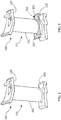
- a component 100 includes any combustion and/or turbine component having surfaces that are exposed to elevated temperatures, such as, but not limited to, a shroud, a blade, a bucket, any other hot gas path component, or a combination thereof.
- the component 100 includes a nozzle 101 configured for use in a hot gas path of a turbine engine.
- the nozzle 101 includes an airfoil portion 103 positioned between a first end wall 105 and a second end wall 107.
- the component 100 includes at least one article 201 secured to the first end wall 105 ( FIG. 2 ) and/or the second end wall 107 ( FIG.
- FIGS. 2-4 Although shown in FIGS. 2-4 as being secured to the first end wall 105, the second end wall 107, or the airfoil portion 103, as will be appreciated by those skilled in the art, the disclosure is not so limited and may include at least one of the articles 201 secured to any one, two, or all three of the first end wall 105, the second end wall 107, and the airfoil portion 103.
- the article 201 may be secured to the first end wall 105 and/or the second end wall 107 and/or the airfoil portion 103 through any suitable method, such as, but not limited to, brazing, sintering, welding, or a combination thereof.
- the component 100 includes any suitable material having any suitable microstructure for continuous use in a turbine engine and/or within the hot gas path of the turbine engine. Suitable microstructures include, but are not limited to, equiaxed, directionally solidified (DS), single crystal (SX), or a combination thereof. Suitable materials of the component 100 include, but are not limited to, a metal, a ceramic, an alloy, a superalloy, steel, a stainless steel, a tool steel, nickel, cobalt, chrome, titanium, aluminum, or a combination thereof.
- the material of the component 100 is a cobalt-based material including, but not limited to, a composition, by weight, of about 29% chromium (Cr), about 10% nickel (Ni), about 7% tungsten (W), about 1% iron (Fe), about 0.25% carbon (C), about 0.01% boron (B), and a balance of cobalt (Co) (e.g., FSX414); about 20% to about 24% Cr, about 20% to about 24% Ni, about 13% to about 15% W, about 3% Fe, about 1.25% manganese (Mn), about 0.2% to about 0.5% silicon (Si), about 0.015% B, about 0.05% to about 0.15% C, about 0.02% to about 0.12% lanthanum (La), and a balance of Co (e.g., HAYNES ® 188); about 22.5% to about 24.25% Cr, about 9% to about 11% Ni, about 6.5% to about 7.5% W, about 3% to about 4% tanta
- Co cobalt
- the material of the component 100 is a nickel-based material including, but not limited to, a composition, by weight, of about 9.75% Cr, about 7.5% Co, about 6.0% W, about 4.2% aluminum (Al), about 3.5% Ti, about 1.5% molybdenum (Mo), about 4.8% Ta, about 0.5% niobium (Nb), about 0.15% hafnium (Hf), about 0.05% C, about 0.004% B, and a balance of Ni (e.g., René N4); about 7.5% Co, about 7.0% Cr, about 6.5% Ta, about 6.2% Al, about 5.0% W, about 3.0% rhenium (Re), about 1.5% Mo, about 0.15% Hf, about 0.05% C, about 0.004% B, about 0.01% yttrium (Y), and a balance of Ni (e.g., René N5); refers to an alloy including a composition, by weight, of about 7.5% Co, about 13% Cr, about 6.6% Al, about 5% Ta, about 3.
- the material of the component 100 is an iron-based material including, but not limited to, a composition, by weight, of about 50% to about 55% Ni and Co combined, about 17% to about 21% Cr, about 4.75% to about 5.50% Nb and Ta combined, about 0.08% C, about 0.35% Mn, about 0.35% Si, about 0.015% P, about 0.015% S, about 1.0% Co, about 0.35% to 0.80% Al, about 2.80% to about 3.30% Mo, about 0.65% to about 1.15% Ti, about 0.001% to about 0.006% B, about 0.15% Cu, and a balance of Fe (e.g., INCONEL ® 718).
- Other materials of the component 100 include, but are not limited to, a CoCrMo alloy, such as, for example, 70Co-27Cr-3Mo; a ceramic matrix composite (CMC); or a combination thereof.
- the article 201 includes any material suitable for being secured directly or indirectly to the first end wall 105 and/or the second end wall 107, and/or for continuous use in a turbine engine and/or within the hot gas path of the turbine engine.
- the article 201 is a single piece.
- the article 201 is provided as multiple pieces. The number of pieces in which the article 201 is provided may depend on how much surface area coverage is required for the component 100 and the complexity of the flow path surface contours on the article 201 or on the component 100.
- the material of the article 201 may be the same, substantially the same, or different from the material of the component 100.
- the material of the article 201 includes a pre-sintered preform (PSP).
- the PSP contains at least two materials with various mixing percentages.
- a first material includes, for example, any of the materials suitable for the hot-gas path of a turbine system disclosed herein.
- a second material includes, for example, a braze alloy, such as, but not limited to, a nickel braze alloy material having a composition, by weight, of between about 13% and about 15% Cr, between about 9% and about 11% Co, between about 2.25% and about 2.75% Ta, between about 3.25% and about 3.75% Al, between about 2.5% and about 3% B, up to about 0.1% Y (for example, between about 0.02% and about 0.1% Y), and a balance of Ni; or between about 18.5% and about 19.5% Cr, between about 9.5% and about 10.5% Si, about 0.1% Co, about 0.03% B, about 0.06% C, and a balance of Ni.
- a braze alloy such as, but not limited to, a nickel braze alloy material having a composition, by weight, of between about 13% and about 15% Cr, between about 9% and about 11% Co, between about 2.25% and about 2.75% Ta, between about 3.25% and about 3.75% Al, between about 2.5% and about 3% B, up to about 0.
- the first material is a high melt powder and the second material is a low melt powder.
- the material of the article 201 is therefore a mixture of a high melt powder and a low melt powder sintered to make the article 201 rigid.
- the ratio of high melt powder to low melt powder is preferably in the range of 70:30 to 35:65, alternatively in the range of 60:40 to 45:55, alternatively 60:40, or ranges or sub-ranges therebetween.
- the high melt powder is a composition, by weight, including, but not limited to, about 9.3% to about 9.7% W, about 9.0% to about 9.5% Co, about 8.0% to about 8.5% Cr, about 5.4% to about 5.7% Al, up to about 0.25% Si, up to about 0.1% Mn, about 0.06% to about 0.09% C, incidental impurities, and a balance of Ni (e.g., Mar-M-247); about 6.8% Cr, about 12% Co, about 6.1% Al, about 4.9% W, about 1.5% Mo, about 2.8% Re, about 6.4% Ta, about 1.5% Hf, and a balance of Ni (e.g., René 142); about 7.6% Cr, about 3.1% Co, about 7.8% Al, about 5.5% Ta, about 0.1% Mo, about 3.9% W, about 1.7% Re, about 0.15% Hf, and a balance ofNi (e.g., René 195); or about 7.5% Co, about 13% Cr, about 6.6% Al, about 5% Ta, about 3.8% W,
- the low melt powder is a composition, by weight, including, but not limited to, about 71% Ni, about 19% Cr, and about 10% Si (e.g., AMS4782); about 14.0% Cr, about 10.0% Co, about 3.5% Al, about 2.7% B, about 0.02% Y, and a balance of Ni (e.g., DF4B); between about 13% and about 15% Cr, between about 9% and about 11% Co, between about 3.2% and about 3.8% Al, between about 2.2% and about 2.8% Ta, between about 2.5% and about 3.0% B, up to about 0.10% Y (optionally present), and a balance of Ni; between about 14% and about 16% Co, between about 19% and about 21% Cr, between about 4.6% and about 5.4% Al, a maximum of about 0.02% B, a maximum of about 0.05% C, between about 7.5% and about 8.1% Si, a maximum of about 0.05% Fe, and a balance of Ni; or about 15.3% Cr, about 10.3% Co, about 3.5% Ta,
- material of the article 201 is a high melt powder of Mar-M-247, a low melt powder of AMS4782 and the ratio of high melt powder to low melt powder is 60:40.
- the PSP pieces may be held in place on one or more of the nozzle surfaces by tack welding to enable positioning and retention of the article 201 during a brazing cycle. More specifically, the tack welding may involve resistance welding or fusion welding. In some embodiments, the brazing is vacuum brazing.
- a bond coat followed by a thermal barrier coating are applied to the article 201 and/or the component 100.
- the article 201 includes a contoured proximal face 202 and a contoured distal face 203.
- the contoured proximal face 202 and/or the contoured distal face 203 are formed through any suitable method, such as, but not limited to, contouring of the article 201 during manufacturing, contouring of the article 201 after manufacturing, bending of the article 201, machining of the article 201, or a combination thereof.
- the contoured proximal face 202 and the contoured distal face 203 may also be formed simultaneously or separately, and include the same, substantially the same, or different shapes and/or contours.
- the contoured proximal face 202 is arranged and disposed for securing the article 201 directly or indirectly to the first end wall 105 and/or the second end wall 107 and/or the airfoil portion 103 of the component 100.
- the contoured proximal face 202 is arranged and disposed for securing the article 201 directly or indirectly to the first end wall 105 and/or the second end wall 107 and/or the airfoil portion 103 of the component 100.
- FIGS. 4 , 5 , 6 , and 8 the contoured proximal face 202 is arranged and disposed for securing the article 201 directly or indirectly to the first end wall 105 and/or the second end wall 107 and/or the airfoil portion 103 of the component 100.
- the contoured proximal face 202 is secured directly to the first end wall 105 and/or the second end wall 107 and/or the airfoil portion 103, and includes a shape and/or contour that, prior to securing the article 201 to the first end wall 105 and/or the second end wall 107 and/or the airfoil portion 103, mirrors or substantially mirrors the shape and/or contour of the first end wall 105 and/or the second end wall 107 and/or the airfoil portion 103.
- mirrors or “substantially mirrors” it is meant that the contoured proximal face 202 of the article 201 has a geometry that follows a geometry of the first end wall 105 and/or the second end wall 107 and/or the airfoil portion 103, providing direct contact between the surfaces thereof.
- the shape and/or contour of the contoured proximal face 202 provides a closer tolerance between the article 201 and the first end wall 105 ( FIG. 6 ) and/or the second end wall 107 and/or the airfoil portion 103.
- the closer tolerance provided by the article 201 decreases or eliminates the formation of gaps and/or increases joint quality between the article 201 and the first end wall 105 and/or the second end wall 107 and/or the airfoil portion 103. This increases manufacturing yield of the component 100, increases a life cycle of the component 100, increases cooling effectiveness of the component 100, or a combination thereof.
- the contoured distal face 203 which is positioned opposite or substantially opposite the contoured proximal face 202 with respect to the article 201, forms an exterior surface over the first end wall 105 and/or the second end wall 107.
- the exterior surface formed by the contoured distal face 203 may be the same, substantially the same, or different from the first end wall 105 and/or the second end wall 107, and provides any suitable surface characteristic over the first end wall 105 and/or the second end wall 107.
- the surface characteristic may be the same as the first end wall 105 and/or the second end wall 107 and/or the airfoil portion 103, or may include a modified surface characteristic. Suitable modified surface characteristics include, but are not limited to, hardness, corrosion resistance, temperature resistance, machinability, or a combination thereof.
- At least one intermediate member 701 is positioned between the article 201 and the first end wall 105 and/or the second end wall 107 and/or the airfoil portion 103.
- the intermediate member 701 includes any material or combination of materials suitable for indirectly securing the article 201 to the first end wall 105 and/or the second end wall 107.
- the intermediate members 701 includes a paste, slurry, powder, or other material configuration as an intermediate member 701 material for facilitating the securing of the article 201 to the first end wall 105 and/or the second end wall 107 and/or the airfoil portion 103.
- the intermediate member 701 may be used to prevent separation between multiple pieces when the article 201 pieces are set on the surface of the nozzle.
- the intermediate member 701 may be applied to enable smooth transitions to other features, if necessary.
- the intermediate member 701 includes a first surface and a second surface that are arranged and disposed to indirectly secure the article 201 to the first end wall 105 and/or the second end wall 107 and/or the airfoil portion 103.
- the contoured distal face 203 forms the exterior surface over the first end wall 105 and/or the second end wall 107 and/or the airfoil portion 103.
- the first surface of the intermediate member 701 includes a shape and/or contour that mirrors or substantially mirrors the shape and/or contour of the first end wall 105 and/or the second end wall 107 and/or the airfoil portion 103
- the second surface of the intermediate member 701 includes a shape and/or contour that mirrors or substantially mirrors the shape and/or contour of the contoured proximal face 202 of the article 201.
- the second surface of the intermediate member 701 provides an intermediate surface over the first end wall 105 and/or the second end wall 107 and/or the airfoil portion 103.
- the intermediate surface facilitates securing of the contoured proximal face 202 thereto, which, in combination with the contoured proximal face 202, provides closer tolerance between the article 201 and the first end wall 105 and/or the second end wall 107 and/or the airfoil portion 103, as compared to the flat surface 603 shown in FIG. 7 .
- alloy compositions described herein may include incidental impurities.
Landscapes
- Engineering & Computer Science (AREA)
- Mechanical Engineering (AREA)
- General Engineering & Computer Science (AREA)
- Chemical & Material Sciences (AREA)
- Materials Engineering (AREA)
- Turbine Rotor Nozzle Sealing (AREA)
Applications Claiming Priority (1)
| Application Number | Priority Date | Filing Date | Title |
|---|---|---|---|
| US15/134,758 US10767501B2 (en) | 2016-04-21 | 2016-04-21 | Article, component, and method of making a component |
Publications (2)
| Publication Number | Publication Date |
|---|---|
| EP3236013A1 true EP3236013A1 (de) | 2017-10-25 |
| EP3236013B1 EP3236013B1 (de) | 2024-04-03 |
Family
ID=58644827
Family Applications (1)
| Application Number | Title | Priority Date | Filing Date |
|---|---|---|---|
| EP17166868.4A Active EP3236013B1 (de) | 2016-04-21 | 2017-04-18 | Artikel, komponente und verfahren zur herstellung einer komponente eines gasturbinentriebwerks |
Country Status (4)
| Country | Link |
|---|---|
| US (1) | US10767501B2 (de) |
| EP (1) | EP3236013B1 (de) |
| JP (1) | JP7076948B2 (de) |
| CN (1) | CN107304687B (de) |
Families Citing this family (1)
| Publication number | Priority date | Publication date | Assignee | Title |
|---|---|---|---|---|
| FR3101108B1 (fr) * | 2019-09-24 | 2022-09-02 | Safran Helicopter Engines | Aube, notamment de turbomachine, partiellement recouverte en pied d’aube d’une bande de protection contre l’oxydation et la corrosion |
Citations (6)
| Publication number | Priority date | Publication date | Assignee | Title |
|---|---|---|---|---|
| GB2071777A (en) * | 1980-03-19 | 1981-09-23 | Gen Electric | Method and replacement member for repairing a gas turbine engine vane assembly |
| EP1977852A1 (de) * | 2007-04-05 | 2008-10-08 | United Technologies Corporation | Verfahren zur Reparatur einer Komponente für einen Turbinenmotor |
| EP2412930A2 (de) * | 2010-07-28 | 2012-02-01 | General Electric Company | Turbinenleitschaufelsegment und Reparaturverfahren dafür |
| EP2949418A1 (de) * | 2014-05-30 | 2015-12-02 | Alstom Technology Ltd. | Verfahren zum Reparieren einer Turbinenschaufelspitze |
| US20150375322A1 (en) * | 2014-06-30 | 2015-12-31 | General Electric Company | Braze methods and components with heat resistant materials |
| US20160067836A1 (en) * | 2014-09-10 | 2016-03-10 | Pw Power Systems, Inc. | Repair or remanufacture of blade platform for a gas turbine engine |
Family Cites Families (33)
| Publication number | Priority date | Publication date | Assignee | Title |
|---|---|---|---|---|
| US4185369A (en) * | 1978-03-22 | 1980-01-29 | General Electric Company | Method of manufacture of cooled turbine or compressor buckets |
| US6413040B1 (en) * | 2000-06-13 | 2002-07-02 | General Electric Company | Support pedestals for interconnecting a cover and nozzle band wall in a gas turbine nozzle segment |
| JP4342276B2 (ja) * | 2003-11-12 | 2009-10-14 | 株式会社東芝 | ガスタービン部品の拡散ろう付補修方法 |
| EP1557535A1 (de) * | 2004-01-20 | 2005-07-27 | Siemens Aktiengesellschaft | Turbinenschaufel und Gasturbine mit einer solchen Turbinenschaufel |
| US7363707B2 (en) * | 2004-06-14 | 2008-04-29 | General Electric Company | Braze repair of shroud block seal teeth in a gas turbine engine |
| US7282681B2 (en) * | 2005-05-05 | 2007-10-16 | General Electric Company | Microwave fabrication of airfoil tips |
| FR2889091B1 (fr) * | 2005-07-29 | 2007-10-19 | Snecma | Procede de reparation d'une aube d'un disque aubage monobloc de turbomachine et eprouvette pour la mise en oeuvre du procede |
| US20080075619A1 (en) * | 2006-09-27 | 2008-03-27 | Laxmappa Hosamani | Method for making molybdenum parts using metal injection molding |
| US8708658B2 (en) * | 2007-04-12 | 2014-04-29 | United Technologies Corporation | Local application of a protective coating on a shrouded gas turbine engine component |
| US9982332B2 (en) * | 2008-05-16 | 2018-05-29 | Consolidated Nuclear Security, LLC | Hardface coating systems and methods for metal alloys and other materials for wear and corrosion resistant applications |
| EP2385155B1 (de) * | 2008-05-26 | 2015-06-24 | Siemens Aktiengesellschaft | Keramisches wärmedämmendes Beschichtungssystem mit zwei Keramikschichten |
| US8096751B2 (en) * | 2008-07-31 | 2012-01-17 | Siemens Energy, Inc. | Turbine engine component with cooling passages |
| US8721285B2 (en) | 2009-03-04 | 2014-05-13 | Siemens Energy, Inc. | Turbine blade with incremental serpentine cooling channels beneath a thermal skin |
| US8440314B2 (en) * | 2009-08-25 | 2013-05-14 | TDY Industries, LLC | Coated cutting tools having a platinum group metal concentration gradient and related processes |
| FR2953885B1 (fr) * | 2009-12-14 | 2012-02-10 | Snecma | Aube de turbomachine en materiau composite et procede pour sa fabrication |
| US8714909B2 (en) | 2010-12-22 | 2014-05-06 | United Technologies Corporation | Platform with cooling circuit |
| US8870523B2 (en) * | 2011-03-07 | 2014-10-28 | General Electric Company | Method for manufacturing a hot gas path component and hot gas path turbine component |
| US8961134B2 (en) * | 2011-06-29 | 2015-02-24 | Siemens Energy, Inc. | Turbine blade or vane with separate endwall |
| US9272332B2 (en) * | 2011-09-29 | 2016-03-01 | GM Global Technology Operations LLC | Near net shape manufacturing of rare earth permanent magnets |
| EP2581164A1 (de) * | 2011-10-14 | 2013-04-17 | Siemens Aktiengesellschaft | Verfahren zum Reparieren von Oberflächenschäden einer Strömungsmaschinenkomponente |
| FR2981602B1 (fr) * | 2011-10-25 | 2017-02-17 | Snecma Propulsion Solide | Procede de fabrication d'un secteur de distributeur de turbine ou redresseur de compresseur en materiau composite pour turbomachine et turbine ou compresseur incorporant un distributeur ou un redresseur forme de tels secteurs |
| US9174314B2 (en) * | 2011-11-03 | 2015-11-03 | Siemens Energy, Inc. | Isothermal structural repair of superalloy components including turbine blades |
| EP2644834A1 (de) * | 2012-03-29 | 2013-10-02 | Siemens Aktiengesellschaft | Turbinenschaufel sowie zugehöriges Verfahren zum Herstellen einer Turbinenschaufel |
| US9863249B2 (en) * | 2012-12-04 | 2018-01-09 | Siemens Energy, Inc. | Pre-sintered preform repair of turbine blades |
| US9015944B2 (en) | 2013-02-22 | 2015-04-28 | General Electric Company | Method of forming a microchannel cooled component |
| US9394796B2 (en) * | 2013-07-12 | 2016-07-19 | General Electric Company | Turbine component and methods of assembling the same |
| US9126279B2 (en) * | 2013-09-30 | 2015-09-08 | General Electric Company | Brazing method |
| US20160376899A1 (en) * | 2013-11-25 | 2016-12-29 | General Electric Technology Gmbh | Guide vane assembly on the basis of a modular structure |
| US9970307B2 (en) * | 2014-03-19 | 2018-05-15 | Honeywell International Inc. | Turbine nozzles with slip joints impregnated by oxidation-resistant sealing material and methods for the production thereof |
| US20150377037A1 (en) | 2014-06-30 | 2015-12-31 | General Electric Company | Braze methods and components for turbine buckets |
| US9517507B2 (en) * | 2014-07-17 | 2016-12-13 | Pratt & Whitney Canada Corp. | Method of shaping green part and manufacturing method using same |
| US9796048B2 (en) * | 2014-08-29 | 2017-10-24 | General Electric Company | Article and process for producing an article |
| DE102014224865A1 (de) * | 2014-12-04 | 2016-06-09 | Siemens Aktiengesellschaft | Verfahren zur Beschichtung einer Turbinenschaufel |
-
2016
- 2016-04-21 US US15/134,758 patent/US10767501B2/en active Active
-
2017
- 2017-04-07 JP JP2017076369A patent/JP7076948B2/ja active Active
- 2017-04-18 EP EP17166868.4A patent/EP3236013B1/de active Active
- 2017-04-21 CN CN201710269085.7A patent/CN107304687B/zh active Active
Patent Citations (6)
| Publication number | Priority date | Publication date | Assignee | Title |
|---|---|---|---|---|
| GB2071777A (en) * | 1980-03-19 | 1981-09-23 | Gen Electric | Method and replacement member for repairing a gas turbine engine vane assembly |
| EP1977852A1 (de) * | 2007-04-05 | 2008-10-08 | United Technologies Corporation | Verfahren zur Reparatur einer Komponente für einen Turbinenmotor |
| EP2412930A2 (de) * | 2010-07-28 | 2012-02-01 | General Electric Company | Turbinenleitschaufelsegment und Reparaturverfahren dafür |
| EP2949418A1 (de) * | 2014-05-30 | 2015-12-02 | Alstom Technology Ltd. | Verfahren zum Reparieren einer Turbinenschaufelspitze |
| US20150375322A1 (en) * | 2014-06-30 | 2015-12-31 | General Electric Company | Braze methods and components with heat resistant materials |
| US20160067836A1 (en) * | 2014-09-10 | 2016-03-10 | Pw Power Systems, Inc. | Repair or remanufacture of blade platform for a gas turbine engine |
Also Published As
| Publication number | Publication date |
|---|---|
| US20170306774A1 (en) | 2017-10-26 |
| CN107304687B (zh) | 2022-03-01 |
| EP3236013B1 (de) | 2024-04-03 |
| CN107304687A (zh) | 2017-10-31 |
| JP2017207057A (ja) | 2017-11-24 |
| JP7076948B2 (ja) | 2022-05-30 |
| US10767501B2 (en) | 2020-09-08 |
Similar Documents
| Publication | Publication Date | Title |
|---|---|---|
| US11731206B2 (en) | Repair of through-hole damage using braze sintered preform | |
| US9796048B2 (en) | Article and process for producing an article | |
| US7651023B2 (en) | Nickel-based braze alloy compositions and related processes and articles | |
| EP3072612A2 (de) | Komponente und verfahren zur herstellung einer komponente | |
| JP7038545B2 (ja) | 拡散合金インサートを用いた難溶接超合金部品のろう付け構造補修 | |
| EP2962798B1 (de) | Verfahren zur herstellung einer faserverstärkten gelöteten komponente | |
| JP2006188760A (ja) | ニッケル基超合金の補修方法、補修のための予備成形体並びにこれにより補修された構成要素 | |
| EP3434395B1 (de) | Verfahren zur herstellung einer komponente mittels generativer fertigung | |
| EP0457503A1 (de) | Hartlotlegierungen und ihre Verwendung | |
| JP2018168851A5 (de) | ||
| EP3381603B1 (de) | Hybridartikel, verfahren zur herstellung eines hybridartikels und verfahren zum schweissen | |
| EP3178589B1 (de) | Verfahren zur herstellung eines hybriden artikels | |
| US20230398621A1 (en) | Amorphous ductile braze alloy compositions, and related methods and articles | |
| EP3332898B1 (de) | Heterogene zusammensetzung, artikel mit heterogener zusammensetzung und verfahren zur formung des artikels | |
| EP3236014A1 (de) | Artikel, komponente und verfahren zur herstellung einer komponente eines gasturbinentriebwerks | |
| JP7229994B2 (ja) | 予備焼結プリフォームおよびプロセス | |
| US10767501B2 (en) | Article, component, and method of making a component | |
| EP3385019B1 (de) | Plattierter artikel und verfahren zur herstellung eines plattierten artikels | |
| JP2018185135A (ja) | 構成要素用の冷却構造を設ける方法 |
Legal Events
| Date | Code | Title | Description |
|---|---|---|---|
| PUAI | Public reference made under article 153(3) epc to a published international application that has entered the european phase |
Free format text: ORIGINAL CODE: 0009012 |
|
| STAA | Information on the status of an ep patent application or granted ep patent |
Free format text: STATUS: THE APPLICATION HAS BEEN PUBLISHED |
|
| AK | Designated contracting states |
Kind code of ref document: A1 Designated state(s): AL AT BE BG CH CY CZ DE DK EE ES FI FR GB GR HR HU IE IS IT LI LT LU LV MC MK MT NL NO PL PT RO RS SE SI SK SM TR |
|
| AX | Request for extension of the european patent |
Extension state: BA ME |
|
| STAA | Information on the status of an ep patent application or granted ep patent |
Free format text: STATUS: REQUEST FOR EXAMINATION WAS MADE |
|
| 17P | Request for examination filed |
Effective date: 20180425 |
|
| RBV | Designated contracting states (corrected) |
Designated state(s): AL AT BE BG CH CY CZ DE DK EE ES FI FR GB GR HR HU IE IS IT LI LT LU LV MC MK MT NL NO PL PT RO RS SE SI SK SM TR |
|
| STAA | Information on the status of an ep patent application or granted ep patent |
Free format text: STATUS: EXAMINATION IS IN PROGRESS |
|
| 17Q | First examination report despatched |
Effective date: 20210316 |
|
| GRAP | Despatch of communication of intention to grant a patent |
Free format text: ORIGINAL CODE: EPIDOSNIGR1 |
|
| STAA | Information on the status of an ep patent application or granted ep patent |
Free format text: STATUS: GRANT OF PATENT IS INTENDED |
|
| INTG | Intention to grant announced |
Effective date: 20230705 |
|
| GRAJ | Information related to disapproval of communication of intention to grant by the applicant or resumption of examination proceedings by the epo deleted |
Free format text: ORIGINAL CODE: EPIDOSDIGR1 |
|
| STAA | Information on the status of an ep patent application or granted ep patent |
Free format text: STATUS: EXAMINATION IS IN PROGRESS |
|
| INTC | Intention to grant announced (deleted) | ||
| RAP1 | Party data changed (applicant data changed or rights of an application transferred) |
Owner name: GENERAL ELECTRIC TECHNOLOGY GMBH |
|
| GRAP | Despatch of communication of intention to grant a patent |
Free format text: ORIGINAL CODE: EPIDOSNIGR1 |
|
| STAA | Information on the status of an ep patent application or granted ep patent |
Free format text: STATUS: GRANT OF PATENT IS INTENDED |
|
| INTG | Intention to grant announced |
Effective date: 20240108 |
|
| GRAS | Grant fee paid |
Free format text: ORIGINAL CODE: EPIDOSNIGR3 |
|
| GRAA | (expected) grant |
Free format text: ORIGINAL CODE: 0009210 |
|
| STAA | Information on the status of an ep patent application or granted ep patent |
Free format text: STATUS: THE PATENT HAS BEEN GRANTED |
|
| AK | Designated contracting states |
Kind code of ref document: B1 Designated state(s): AL AT BE BG CH CY CZ DE DK EE ES FI FR GB GR HR HU IE IS IT LI LT LU LV MC MK MT NL NO PL PT RO RS SE SI SK SM TR |
|
| REG | Reference to a national code |
Ref country code: GB Ref legal event code: FG4D |
|
| REG | Reference to a national code |
Ref country code: CH Ref legal event code: EP |
|
| REG | Reference to a national code |
Ref country code: DE Ref legal event code: R096 Ref document number: 602017080531 Country of ref document: DE |
|
| REG | Reference to a national code |
Ref country code: IE Ref legal event code: FG4D |
|
| REG | Reference to a national code |
Ref country code: LT Ref legal event code: MG9D |
|
| REG | Reference to a national code |
Ref country code: NL Ref legal event code: MP Effective date: 20240403 |
|
| REG | Reference to a national code |
Ref country code: AT Ref legal event code: MK05 Ref document number: 1672520 Country of ref document: AT Kind code of ref document: T Effective date: 20240403 |
|
| PG25 | Lapsed in a contracting state [announced via postgrant information from national office to epo] |
Ref country code: NL Free format text: LAPSE BECAUSE OF FAILURE TO SUBMIT A TRANSLATION OF THE DESCRIPTION OR TO PAY THE FEE WITHIN THE PRESCRIBED TIME-LIMIT Effective date: 20240403 |
|
| PG25 | Lapsed in a contracting state [announced via postgrant information from national office to epo] |
Ref country code: NL Free format text: LAPSE BECAUSE OF FAILURE TO SUBMIT A TRANSLATION OF THE DESCRIPTION OR TO PAY THE FEE WITHIN THE PRESCRIBED TIME-LIMIT Effective date: 20240403 |
|
| PG25 | Lapsed in a contracting state [announced via postgrant information from national office to epo] |
Ref country code: IS Free format text: LAPSE BECAUSE OF FAILURE TO SUBMIT A TRANSLATION OF THE DESCRIPTION OR TO PAY THE FEE WITHIN THE PRESCRIBED TIME-LIMIT Effective date: 20240803 |
|
| PG25 | Lapsed in a contracting state [announced via postgrant information from national office to epo] |
Ref country code: BG Free format text: LAPSE BECAUSE OF FAILURE TO SUBMIT A TRANSLATION OF THE DESCRIPTION OR TO PAY THE FEE WITHIN THE PRESCRIBED TIME-LIMIT Effective date: 20240403 |
|
| PG25 | Lapsed in a contracting state [announced via postgrant information from national office to epo] |
Ref country code: HR Free format text: LAPSE BECAUSE OF FAILURE TO SUBMIT A TRANSLATION OF THE DESCRIPTION OR TO PAY THE FEE WITHIN THE PRESCRIBED TIME-LIMIT Effective date: 20240403 Ref country code: FI Free format text: LAPSE BECAUSE OF FAILURE TO SUBMIT A TRANSLATION OF THE DESCRIPTION OR TO PAY THE FEE WITHIN THE PRESCRIBED TIME-LIMIT Effective date: 20240403 |
|
| PG25 | Lapsed in a contracting state [announced via postgrant information from national office to epo] |
Ref country code: GR Free format text: LAPSE BECAUSE OF FAILURE TO SUBMIT A TRANSLATION OF THE DESCRIPTION OR TO PAY THE FEE WITHIN THE PRESCRIBED TIME-LIMIT Effective date: 20240704 |
|
| PG25 | Lapsed in a contracting state [announced via postgrant information from national office to epo] |
Ref country code: PT Free format text: LAPSE BECAUSE OF FAILURE TO SUBMIT A TRANSLATION OF THE DESCRIPTION OR TO PAY THE FEE WITHIN THE PRESCRIBED TIME-LIMIT Effective date: 20240805 |
|
| PG25 | Lapsed in a contracting state [announced via postgrant information from national office to epo] |
Ref country code: ES Free format text: LAPSE BECAUSE OF FAILURE TO SUBMIT A TRANSLATION OF THE DESCRIPTION OR TO PAY THE FEE WITHIN THE PRESCRIBED TIME-LIMIT Effective date: 20240403 |
|
| PG25 | Lapsed in a contracting state [announced via postgrant information from national office to epo] |
Ref country code: CZ Free format text: LAPSE BECAUSE OF FAILURE TO SUBMIT A TRANSLATION OF THE DESCRIPTION OR TO PAY THE FEE WITHIN THE PRESCRIBED TIME-LIMIT Effective date: 20240403 |
|
| PG25 | Lapsed in a contracting state [announced via postgrant information from national office to epo] |
Ref country code: AT Free format text: LAPSE BECAUSE OF FAILURE TO SUBMIT A TRANSLATION OF THE DESCRIPTION OR TO PAY THE FEE WITHIN THE PRESCRIBED TIME-LIMIT Effective date: 20240403 |
|
| PG25 | Lapsed in a contracting state [announced via postgrant information from national office to epo] |
Ref country code: PL Free format text: LAPSE BECAUSE OF FAILURE TO SUBMIT A TRANSLATION OF THE DESCRIPTION OR TO PAY THE FEE WITHIN THE PRESCRIBED TIME-LIMIT Effective date: 20240403 |
|
| PG25 | Lapsed in a contracting state [announced via postgrant information from national office to epo] |
Ref country code: LV Free format text: LAPSE BECAUSE OF FAILURE TO SUBMIT A TRANSLATION OF THE DESCRIPTION OR TO PAY THE FEE WITHIN THE PRESCRIBED TIME-LIMIT Effective date: 20240403 |
|
| PG25 | Lapsed in a contracting state [announced via postgrant information from national office to epo] |
Ref country code: PT Free format text: LAPSE BECAUSE OF FAILURE TO SUBMIT A TRANSLATION OF THE DESCRIPTION OR TO PAY THE FEE WITHIN THE PRESCRIBED TIME-LIMIT Effective date: 20240805 Ref country code: PL Free format text: LAPSE BECAUSE OF FAILURE TO SUBMIT A TRANSLATION OF THE DESCRIPTION OR TO PAY THE FEE WITHIN THE PRESCRIBED TIME-LIMIT Effective date: 20240403 Ref country code: NO Free format text: LAPSE BECAUSE OF FAILURE TO SUBMIT A TRANSLATION OF THE DESCRIPTION OR TO PAY THE FEE WITHIN THE PRESCRIBED TIME-LIMIT Effective date: 20240703 Ref country code: LV Free format text: LAPSE BECAUSE OF FAILURE TO SUBMIT A TRANSLATION OF THE DESCRIPTION OR TO PAY THE FEE WITHIN THE PRESCRIBED TIME-LIMIT Effective date: 20240403 Ref country code: IS Free format text: LAPSE BECAUSE OF FAILURE TO SUBMIT A TRANSLATION OF THE DESCRIPTION OR TO PAY THE FEE WITHIN THE PRESCRIBED TIME-LIMIT Effective date: 20240803 Ref country code: HR Free format text: LAPSE BECAUSE OF FAILURE TO SUBMIT A TRANSLATION OF THE DESCRIPTION OR TO PAY THE FEE WITHIN THE PRESCRIBED TIME-LIMIT Effective date: 20240403 Ref country code: GR Free format text: LAPSE BECAUSE OF FAILURE TO SUBMIT A TRANSLATION OF THE DESCRIPTION OR TO PAY THE FEE WITHIN THE PRESCRIBED TIME-LIMIT Effective date: 20240704 Ref country code: FI Free format text: LAPSE BECAUSE OF FAILURE TO SUBMIT A TRANSLATION OF THE DESCRIPTION OR TO PAY THE FEE WITHIN THE PRESCRIBED TIME-LIMIT Effective date: 20240403 Ref country code: ES Free format text: LAPSE BECAUSE OF FAILURE TO SUBMIT A TRANSLATION OF THE DESCRIPTION OR TO PAY THE FEE WITHIN THE PRESCRIBED TIME-LIMIT Effective date: 20240403 Ref country code: CZ Free format text: LAPSE BECAUSE OF FAILURE TO SUBMIT A TRANSLATION OF THE DESCRIPTION OR TO PAY THE FEE WITHIN THE PRESCRIBED TIME-LIMIT Effective date: 20240403 Ref country code: BG Free format text: LAPSE BECAUSE OF FAILURE TO SUBMIT A TRANSLATION OF THE DESCRIPTION OR TO PAY THE FEE WITHIN THE PRESCRIBED TIME-LIMIT Effective date: 20240403 Ref country code: AT Free format text: LAPSE BECAUSE OF FAILURE TO SUBMIT A TRANSLATION OF THE DESCRIPTION OR TO PAY THE FEE WITHIN THE PRESCRIBED TIME-LIMIT Effective date: 20240403 Ref country code: RS Free format text: LAPSE BECAUSE OF FAILURE TO SUBMIT A TRANSLATION OF THE DESCRIPTION OR TO PAY THE FEE WITHIN THE PRESCRIBED TIME-LIMIT Effective date: 20240703 |
|
| REG | Reference to a national code |
Ref country code: CH Ref legal event code: PL |
|
| PG25 | Lapsed in a contracting state [announced via postgrant information from national office to epo] |
Ref country code: LU Free format text: LAPSE BECAUSE OF NON-PAYMENT OF DUE FEES Effective date: 20240418 |
|
| REG | Reference to a national code |
Ref country code: BE Ref legal event code: MM Effective date: 20240430 |
|
| PG25 | Lapsed in a contracting state [announced via postgrant information from national office to epo] |
Ref country code: LU Free format text: LAPSE BECAUSE OF NON-PAYMENT OF DUE FEES Effective date: 20240418 |
|
| REG | Reference to a national code |
Ref country code: DE Ref legal event code: R097 Ref document number: 602017080531 Country of ref document: DE |
|
| PG25 | Lapsed in a contracting state [announced via postgrant information from national office to epo] |
Ref country code: DK Free format text: LAPSE BECAUSE OF FAILURE TO SUBMIT A TRANSLATION OF THE DESCRIPTION OR TO PAY THE FEE WITHIN THE PRESCRIBED TIME-LIMIT Effective date: 20240403 |
|
| PG25 | Lapsed in a contracting state [announced via postgrant information from national office to epo] |
Ref country code: BE Free format text: LAPSE BECAUSE OF NON-PAYMENT OF DUE FEES Effective date: 20240430 |
|
| PG25 | Lapsed in a contracting state [announced via postgrant information from national office to epo] |
Ref country code: EE Free format text: LAPSE BECAUSE OF FAILURE TO SUBMIT A TRANSLATION OF THE DESCRIPTION OR TO PAY THE FEE WITHIN THE PRESCRIBED TIME-LIMIT Effective date: 20240403 |
|
| PG25 | Lapsed in a contracting state [announced via postgrant information from national office to epo] |
Ref country code: SK Free format text: LAPSE BECAUSE OF FAILURE TO SUBMIT A TRANSLATION OF THE DESCRIPTION OR TO PAY THE FEE WITHIN THE PRESCRIBED TIME-LIMIT Effective date: 20240403 Ref country code: RO Free format text: LAPSE BECAUSE OF FAILURE TO SUBMIT A TRANSLATION OF THE DESCRIPTION OR TO PAY THE FEE WITHIN THE PRESCRIBED TIME-LIMIT Effective date: 20240403 |
|
| PG25 | Lapsed in a contracting state [announced via postgrant information from national office to epo] |
Ref country code: SM Free format text: LAPSE BECAUSE OF FAILURE TO SUBMIT A TRANSLATION OF THE DESCRIPTION OR TO PAY THE FEE WITHIN THE PRESCRIBED TIME-LIMIT Effective date: 20240403 |
|
| PG25 | Lapsed in a contracting state [announced via postgrant information from national office to epo] |
Ref country code: SM Free format text: LAPSE BECAUSE OF FAILURE TO SUBMIT A TRANSLATION OF THE DESCRIPTION OR TO PAY THE FEE WITHIN THE PRESCRIBED TIME-LIMIT Effective date: 20240403 Ref country code: SK Free format text: LAPSE BECAUSE OF FAILURE TO SUBMIT A TRANSLATION OF THE DESCRIPTION OR TO PAY THE FEE WITHIN THE PRESCRIBED TIME-LIMIT Effective date: 20240403 Ref country code: RO Free format text: LAPSE BECAUSE OF FAILURE TO SUBMIT A TRANSLATION OF THE DESCRIPTION OR TO PAY THE FEE WITHIN THE PRESCRIBED TIME-LIMIT Effective date: 20240403 Ref country code: EE Free format text: LAPSE BECAUSE OF FAILURE TO SUBMIT A TRANSLATION OF THE DESCRIPTION OR TO PAY THE FEE WITHIN THE PRESCRIBED TIME-LIMIT Effective date: 20240403 Ref country code: DK Free format text: LAPSE BECAUSE OF FAILURE TO SUBMIT A TRANSLATION OF THE DESCRIPTION OR TO PAY THE FEE WITHIN THE PRESCRIBED TIME-LIMIT Effective date: 20240403 Ref country code: BE Free format text: LAPSE BECAUSE OF NON-PAYMENT OF DUE FEES Effective date: 20240430 Ref country code: CH Free format text: LAPSE BECAUSE OF NON-PAYMENT OF DUE FEES Effective date: 20240430 Ref country code: MC Free format text: LAPSE BECAUSE OF FAILURE TO SUBMIT A TRANSLATION OF THE DESCRIPTION OR TO PAY THE FEE WITHIN THE PRESCRIBED TIME-LIMIT Effective date: 20240403 |
|
| PLBE | No opposition filed within time limit |
Free format text: ORIGINAL CODE: 0009261 |
|
| STAA | Information on the status of an ep patent application or granted ep patent |
Free format text: STATUS: NO OPPOSITION FILED WITHIN TIME LIMIT |
|
| 26N | No opposition filed |
Effective date: 20250106 |
|
| GBPC | Gb: european patent ceased through non-payment of renewal fee |
Effective date: 20240703 |
|
| PG25 | Lapsed in a contracting state [announced via postgrant information from national office to epo] |
Ref country code: IE Free format text: LAPSE BECAUSE OF NON-PAYMENT OF DUE FEES Effective date: 20240418 |
|
| PG25 | Lapsed in a contracting state [announced via postgrant information from national office to epo] |
Ref country code: SI Free format text: LAPSE BECAUSE OF FAILURE TO SUBMIT A TRANSLATION OF THE DESCRIPTION OR TO PAY THE FEE WITHIN THE PRESCRIBED TIME-LIMIT Effective date: 20240403 |
|
| PG25 | Lapsed in a contracting state [announced via postgrant information from national office to epo] |
Ref country code: FR Free format text: LAPSE BECAUSE OF NON-PAYMENT OF DUE FEES Effective date: 20240603 |
|
| PG25 | Lapsed in a contracting state [announced via postgrant information from national office to epo] |
Ref country code: GB Free format text: LAPSE BECAUSE OF NON-PAYMENT OF DUE FEES Effective date: 20240703 |
|
| PGFP | Annual fee paid to national office [announced via postgrant information from national office to epo] |
Ref country code: DE Payment date: 20250319 Year of fee payment: 9 |
|
| PG25 | Lapsed in a contracting state [announced via postgrant information from national office to epo] |
Ref country code: CY Free format text: LAPSE BECAUSE OF FAILURE TO SUBMIT A TRANSLATION OF THE DESCRIPTION OR TO PAY THE FEE WITHIN THE PRESCRIBED TIME-LIMIT; INVALID AB INITIO Effective date: 20170418 |
|
| PG25 | Lapsed in a contracting state [announced via postgrant information from national office to epo] |
Ref country code: HU Free format text: LAPSE BECAUSE OF FAILURE TO SUBMIT A TRANSLATION OF THE DESCRIPTION OR TO PAY THE FEE WITHIN THE PRESCRIBED TIME-LIMIT; INVALID AB INITIO Effective date: 20170418 |
|
| PG25 | Lapsed in a contracting state [announced via postgrant information from national office to epo] |
Ref country code: SE Free format text: LAPSE BECAUSE OF FAILURE TO SUBMIT A TRANSLATION OF THE DESCRIPTION OR TO PAY THE FEE WITHIN THE PRESCRIBED TIME-LIMIT Effective date: 20240403 |
|
| PG25 | Lapsed in a contracting state [announced via postgrant information from national office to epo] |
Ref country code: IT Free format text: LAPSE BECAUSE OF FAILURE TO SUBMIT A TRANSLATION OF THE DESCRIPTION OR TO PAY THE FEE WITHIN THE PRESCRIBED TIME-LIMIT Effective date: 20240403 |