EP3236046A1 - Moteur à combustion interne pour un moteur hors-bord - Google Patents
Moteur à combustion interne pour un moteur hors-bord Download PDFInfo
- Publication number
- EP3236046A1 EP3236046A1 EP17000551.6A EP17000551A EP3236046A1 EP 3236046 A1 EP3236046 A1 EP 3236046A1 EP 17000551 A EP17000551 A EP 17000551A EP 3236046 A1 EP3236046 A1 EP 3236046A1
- Authority
- EP
- European Patent Office
- Prior art keywords
- combustion engine
- internal combustion
- cover
- air
- guide
- Prior art date
- Legal status (The legal status is an assumption and is not a legal conclusion. Google has not performed a legal analysis and makes no representation as to the accuracy of the status listed.)
- Withdrawn
Links
- 238000002485 combustion reaction Methods 0.000 title claims abstract description 80
- 238000000034 method Methods 0.000 claims description 4
- 238000001816 cooling Methods 0.000 description 3
- 238000009423 ventilation Methods 0.000 description 3
- 239000000243 solution Substances 0.000 description 2
- 238000010276 construction Methods 0.000 description 1
- 230000000694 effects Effects 0.000 description 1
- 238000002347 injection Methods 0.000 description 1
- 239000007924 injection Substances 0.000 description 1
- 230000001404 mediated effect Effects 0.000 description 1
- 239000003643 water by type Substances 0.000 description 1
Images


Classifications
-
- F—MECHANICAL ENGINEERING; LIGHTING; HEATING; WEAPONS; BLASTING
- F01—MACHINES OR ENGINES IN GENERAL; ENGINE PLANTS IN GENERAL; STEAM ENGINES
- F01P—COOLING OF MACHINES OR ENGINES IN GENERAL; COOLING OF INTERNAL-COMBUSTION ENGINES
- F01P1/00—Air cooling
- F01P1/06—Arrangements for cooling other engine or machine parts
-
- F—MECHANICAL ENGINEERING; LIGHTING; HEATING; WEAPONS; BLASTING
- F02—COMBUSTION ENGINES; HOT-GAS OR COMBUSTION-PRODUCT ENGINE PLANTS
- F02B—INTERNAL-COMBUSTION PISTON ENGINES; COMBUSTION ENGINES IN GENERAL
- F02B61/00—Adaptations of engines for driving vehicles or for driving propellers; Combinations of engines with gearing
- F02B61/04—Adaptations of engines for driving vehicles or for driving propellers; Combinations of engines with gearing for driving propellers
- F02B61/045—Adaptations of engines for driving vehicles or for driving propellers; Combinations of engines with gearing for driving propellers for marine engines
-
- F—MECHANICAL ENGINEERING; LIGHTING; HEATING; WEAPONS; BLASTING
- F01—MACHINES OR ENGINES IN GENERAL; ENGINE PLANTS IN GENERAL; STEAM ENGINES
- F01P—COOLING OF MACHINES OR ENGINES IN GENERAL; COOLING OF INTERNAL-COMBUSTION ENGINES
- F01P5/00—Pumping cooling-air or liquid coolants
- F01P5/02—Pumping cooling-air; Arrangements of cooling-air pumps, e.g. fans or blowers
- F01P5/04—Pump-driving arrangements
-
- F—MECHANICAL ENGINEERING; LIGHTING; HEATING; WEAPONS; BLASTING
- F02—COMBUSTION ENGINES; HOT-GAS OR COMBUSTION-PRODUCT ENGINE PLANTS
- F02B—INTERNAL-COMBUSTION PISTON ENGINES; COMBUSTION ENGINES IN GENERAL
- F02B75/00—Other engines
- F02B75/007—Other engines having vertical crankshafts
-
- F—MECHANICAL ENGINEERING; LIGHTING; HEATING; WEAPONS; BLASTING
- F02—COMBUSTION ENGINES; HOT-GAS OR COMBUSTION-PRODUCT ENGINE PLANTS
- F02B—INTERNAL-COMBUSTION PISTON ENGINES; COMBUSTION ENGINES IN GENERAL
- F02B75/00—Other engines
- F02B75/06—Engines with means for equalising torque
-
- F—MECHANICAL ENGINEERING; LIGHTING; HEATING; WEAPONS; BLASTING
- F02—COMBUSTION ENGINES; HOT-GAS OR COMBUSTION-PRODUCT ENGINE PLANTS
- F02M—SUPPLYING COMBUSTION ENGINES IN GENERAL WITH COMBUSTIBLE MIXTURES OR CONSTITUENTS THEREOF
- F02M35/00—Combustion-air cleaners, air intakes, intake silencers, or induction systems specially adapted for, or arranged on, internal-combustion engines
- F02M35/10—Air intakes; Induction systems
- F02M35/1015—Air intakes; Induction systems characterised by the engine type
- F02M35/10157—Supercharged engines
-
- F—MECHANICAL ENGINEERING; LIGHTING; HEATING; WEAPONS; BLASTING
- F02—COMBUSTION ENGINES; HOT-GAS OR COMBUSTION-PRODUCT ENGINE PLANTS
- F02M—SUPPLYING COMBUSTION ENGINES IN GENERAL WITH COMBUSTIBLE MIXTURES OR CONSTITUENTS THEREOF
- F02M35/00—Combustion-air cleaners, air intakes, intake silencers, or induction systems specially adapted for, or arranged on, internal-combustion engines
- F02M35/10—Air intakes; Induction systems
- F02M35/10242—Devices or means connected to or integrated into air intakes; Air intakes combined with other engine or vehicle parts
- F02M35/10262—Flow guides, obstructions, deflectors or the like
-
- F—MECHANICAL ENGINEERING; LIGHTING; HEATING; WEAPONS; BLASTING
- F02—COMBUSTION ENGINES; HOT-GAS OR COMBUSTION-PRODUCT ENGINE PLANTS
- F02M—SUPPLYING COMBUSTION ENGINES IN GENERAL WITH COMBUSTIBLE MIXTURES OR CONSTITUENTS THEREOF
- F02M35/00—Combustion-air cleaners, air intakes, intake silencers, or induction systems specially adapted for, or arranged on, internal-combustion engines
- F02M35/16—Combustion-air cleaners, air intakes, intake silencers, or induction systems specially adapted for, or arranged on, internal-combustion engines characterised by use in vehicles
- F02M35/165—Marine vessels; Ships; Boats
- F02M35/167—Marine vessels; Ships; Boats having outboard engines; Jet-skis
-
- F—MECHANICAL ENGINEERING; LIGHTING; HEATING; WEAPONS; BLASTING
- F04—POSITIVE - DISPLACEMENT MACHINES FOR LIQUIDS; PUMPS FOR LIQUIDS OR ELASTIC FLUIDS
- F04D—NON-POSITIVE-DISPLACEMENT PUMPS
- F04D29/00—Details, component parts, or accessories
- F04D29/26—Rotors specially for elastic fluids
-
- F—MECHANICAL ENGINEERING; LIGHTING; HEATING; WEAPONS; BLASTING
- F01—MACHINES OR ENGINES IN GENERAL; ENGINE PLANTS IN GENERAL; STEAM ENGINES
- F01P—COOLING OF MACHINES OR ENGINES IN GENERAL; COOLING OF INTERNAL-COMBUSTION ENGINES
- F01P2050/00—Applications
- F01P2050/02—Marine engines
- F01P2050/12—Outboard engine
-
- Y—GENERAL TAGGING OF NEW TECHNOLOGICAL DEVELOPMENTS; GENERAL TAGGING OF CROSS-SECTIONAL TECHNOLOGIES SPANNING OVER SEVERAL SECTIONS OF THE IPC; TECHNICAL SUBJECTS COVERED BY FORMER USPC CROSS-REFERENCE ART COLLECTIONS [XRACs] AND DIGESTS
- Y02—TECHNOLOGIES OR APPLICATIONS FOR MITIGATION OR ADAPTATION AGAINST CLIMATE CHANGE
- Y02T—CLIMATE CHANGE MITIGATION TECHNOLOGIES RELATED TO TRANSPORTATION
- Y02T10/00—Road transport of goods or passengers
- Y02T10/10—Internal combustion engine [ICE] based vehicles
- Y02T10/12—Improving ICE efficiencies
Definitions
- the invention relates to an internal combustion engine for an outboard motor with an air duct system according to the preamble of patent claim 1.
- an internal combustion engine US 6,302,749 B1 working as an outboard engine to power a watercraft.
- the internal combustion engine is surrounded by a cover which defines an interior space.
- far enveloping cover inlet and outlet devices are provided for moving in the interior serving to act on housing surfaces of the internal combustion engine air streams.
- the internal combustion engine comprises an upright multi-piston crankshaft which drives balance shafts at an upper end portion by means of a endless drive.
- An alternator with an upright axis of rotation is provided with a fan that ventilates and vents the interior of a hood-like Endlostriebabdeckung.
- the DE 102 05 109 B4 is an outboard motor again, which is provided with a vertically oriented crankshaft and a plurality of attached to an outer side of a machine housing of the outboard motor ancillaries.
- a cover envelops the outboard motor or ancillaries.
- On a rear side of the cover air inlet slots are provided which cooperate with an adjacent spoiler.
- the air guiding device ensures that fresh air is conducted into an upper and a lower region of the interior of the cover or to the machine housing and to the ancillaries.
- the object of the invention is to design an internal combustion engine for an outboard motor for driving a ship, in which serving in the interior of a surrounding the engine cover a serving with respect to the cooling air and the intake air supply for the internal combustion engine and scales setting air ducting system is provided. But it should also be ensured that the air duct system can be implemented with reasonable means.
- the air duct system which is distinguished by an exemplary function and ease of implementation in conjunction with the disguised by the cover hood engine of the outboard motor.
- the air guide system in the interior of the cover provided with the inlet and outlet openings and by supporting the fan, the air flows in said interior space controlled.
- the air streams entering via the inlet openings are directed system-supporting into the interior space through the intermediary of the first easily representable guide device.
- Part of these air streams act on the exemplary cooling of the surfaces of the housing of the internal combustion engine and their ancillaries.
- another part of the air streams is supplied via a simple second guide the suction system.
- the air duct system ensures that the air currents that cool the surfaces of the internal combustion engine or the ancillary units attached thereto cool. That is, said air streams are ingeniously sucked by the fan, and they arrive as exhaust air through the outlet opening into the atmosphere.
- the inlet opening in the central longitudinal plane of the outboard motor can easily be realized, namely at the upper end region of the rear upright hood wall of the cover hood, wherein the first guide device extends from the inlet opening in the direction of a lower side of the internal combustion engine and has an overflow region towards the interior.
- the guide is formed by a hood portion of the upright hood wall and an inner wall, which hood wall and inner wall constitute a kind of channel.
- a promising solution of the ventilation system is that the fan is driven by the mediation of an upstanding crankshaft of the engine extending beyond the top of the engine. Functionally, as viewed in the direction of travel of the ship, the inlet opening on the rear hood wall and the fan is disposed adjacent to a front hood wall of the cover, which causes a deliberate, Entwüberendes passing of the air flows at the surfaces. It is meaningful that the crankshaft driving the fan together with another crankshaft running parallel to the latter forms a crankshaft system of the internal combustion engine in which the crankshafts are operatively connected to at least one reciprocating piston via two connecting rods.
- This construction is optimizing, if the arranged transversely to the direction of crankshaft crankshaft, at its upper beyond the end wall of the engine protruding ends first and second flywheels, which are considered in the height of the crankshafts offset from each other and overlap each other, wherein the fan with the first upper flywheel is combined, which is thus effective in addition to its function as storage of rotational energy as a drive means for the fan.
- the upper flywheel with blower and the second lower flywheel are covered by means of an upper hood section and a lower hood section, which are designed as a one-piece or multi-part blower flywheel cover.
- the first fan-fitting cylindrical hood section is provided with the third guide device, which via a spiral-like tangential section conveys the blower-conveyed exhaust air via the outlet opening into the atmosphere.
- the lower hood portion on one horizontal cover wall has one or more through openings, for example in the form of vent slots. Good operation of the blower is achieved if it includes a mixed flow impeller system, radial flow or the like.
- the second line device for intake system of the internal combustion engine includes a tubular element extending between the underside of the interior of the cover and lying on an upper side of the engine intake. This is aided by the fact that the second conduit device formed as a tubular element is connected to a compressor of an exhaust gas turbocharging device of the internal combustion engine connected to the intake system and that a pipe section extending adjacent to the underside of the interior of the cover hood is provided with at least one inlet opening.
- the method for operating the air duct system in the interior of the hood of the outboard motor is an ingenious performance, because it is characterized by inlet and outlet openings in the cover, the effectively used baffles and the fan on the flywheel of the crankshaft by a high-level efficiency.
- the outboard motor 1 comprises an internal combustion engine 2, viewed in the direction of travel A of the ship, a rear side 3, a front side 4 and viewed in the vertical direction BB has an upper side 5 and a lower side 6.
- the internal combustion engine 2 is bounded by a left longitudinal side 7 and a right longitudinal side 8.
- On the long sides 7 and 8 are several ancillaries eg 9, 10 and 11- Fig. 3 -built, which are not discussed in more detail.
- a cover 12 surrounds the internal combustion engine 2 with its ancillary units 9, 10 and 11 and their surfaces, and it forms an inner space 13.
- an inlet opening 15 is arranged over the entire Air flows Lges in the interior 13 of the cover 12 flow.
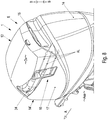
- the latter also has an outlet opening 16 - Fig. 1 and 8th -
- For exhaust air flows AL which is incorporated in an upright, left side hood wall 17, and with a defined distance to the rear hood wall 14.
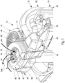
- Lges is a arranged on the top side 5 of the engine 2 blower 18 - Fig. 1 . 3 and 4 - which is driven by the latter.
- a front hood wall bears the reference numeral 14 '- Fig. 1 and 2 -.
- the internal combustion engine 2 of the reciprocating type has at least one reciprocating piston 19 and 20 are in operative connection with the intermediary of two connecting rods with two parallel aligned and rotating in opposite directions of rotation of the first and second crankshafts.
- the first and second crankshafts 19 and 20 of a crankshaft system 21 - Fig. 2 and 6 are relatively upright to a not shown waterline of the ship and drive by means of a drive shaft 22 below a waterline a ship propeller 23 Fig. 1 - at.
- the crankshafts 19 and 20 project beyond the upper side 5 of the internal combustion engine 1, lie transversely to the direction of travel A symmetrically to a central longitudinal plane CC.
- first flywheel 24 and the second flywheel 25 are mounted offset to one another on the crankshafts 19 and 20, wherein they overlap each other in regions for space-saving reasons.
- the first flywheel 24 is located above the second flywheel 25, which first flywheel 24 carries the blower 18 - Fig.1 -.
- the internal combustion engine 2 accommodates the crankshafts 19 and 20 with a housing 26, and the internal combustion engine 2 operates according to the diesel injection method, with an exhaust-gas turbocharging device 27 with compressor 28 and exhaust-gas turbine 29 being provided for optimizing its operation.
- the exhaust-gas turbocharger device 27 is connected to an intake system 30 of the internal combustion engine 2, which exhaust-gas turbocharger device 27 and intake system 30 are arranged on the upper side 5 of the internal combustion engine 1, not far from the rear hood wall 14 of the cover 12. Further details of the internal combustion engine 2 are the one treating similar internal combustion engine, EP 2 980 374 A1 refer to.
- an air guide system 31 is effective.
- the total air streams Lges entering via the inlet opening 15 pass into a first guide device 32 adjoining this inlet opening 15, from where With the assistance of the blower 18, a first part of the air flows TdL1 can act on service-heated surfaces, eg OfL1, OfIL2, OfL3 and OfL4, of the internal combustion engine 1 or ancillary units 9, 10 and 11.
- Another second part of the air flows TdL2 reaches as intake air by means of a second guide 33, the intake system 30 of the internal combustion engine 1.
- the inlet opening 15 is arranged at an upper end region Ebo adjacent to an upper ceiling lining Dv of the hood wall 14, and the first guide 32 extends from the inlet opening 15 upwards in the direction of the underside 6 of the internal combustion engine 2. Adjacent to this underside 6, the guide 32 has an overflow area 35. Fig. 1 and 3 - Towards the interior 13.
- the first guide 32 is formed by a hood wall portion 37 of the hood wall 14 and an upright inner wall 38 of the cover 12; Hood portion 37 and an inner wall 38 form an inflow channel 39 - Fig. 1 and 3 -.
- the fan 18 and the flywheel 24 are structurally combined, in other words they form, for example, in the manner of a module, a prefabricated unit.
- the inlet opening 15 is arranged in the first rear hood wall 14; the fan 18 with crankshaft 19 and flywheel 24 adjacent the front hood wall 14 '.
- a principal area of action Wb - Figure 3 - In the interior 13 of the cover 12.
- the part of the air currents TdI is 1 on the surfaces OfL 1 to Ofl 4 of the internal combustion engine 1 and the ancillary units with defined pressure, caused by the blower 18, bypassed, so that there is a targeted cooling effect on said surfaces OfL1 to OfL 4 OfI 1 to 4.
- the blower 18 is designed so that the suction pressure is about 2 to 3 times higher than the suction pressure of the intake system 30 of the internal combustion engine. 2
- the first upper flywheel 24 with blower 18 is covered with a first upper cylindrical hood portion 40; the second flywheel 25 with a lower cylindrical hood portion 41.
- the upper hood portion 40 is provided with a first cover plate 42 having an inlet opening 43 for the supply air of the blower 18.
- the blower 18 has a mixed flow impeller system 44, radial flow or the like.
- the lower hood portion 41 has a second cover plate 45 provided with a plurality of through holes 46 as radial slots.
- the upper hood portion 40 and the lower hood portion 41, which cover the flywheels 24 and 25, are formed as a one-piece or multi-part blower flywheel cover 47. It comprises e.g. four fastening eyes 48 and is held by means of screws at different locations on the internal combustion engine 2 in position.
- the first upper cylindrical hood portion 40 for the first upper flywheel 24 combined with the blower 18 is provided with a third guide 49 to which is formed a spiral tangential duct portion 50 which controls the exhaust air flows AL drawn and conveyed by the blower 18 through an exit duct 51 of the tangential duct portion 50 and the outlet opening 16 in the cover 12 into the atmosphere or to the outside leads off.
- the second guide 33 to the intake system 30 comprises a tube element 52 which has an upright tube element section 53 and a horizontal tube element section 54, Fig. 4 -.
- the one-piece tubular element sections 53 and 54 are spaced apart from each other Internal combustion engine 1 and have a T-shaped Gestaltt.
- the tubular element 52 with the horizontal tubular element section 54 is connected by means of a connection element 55 - Fig. 7 - Connected to the suction system 30.
- the connection element 55 is connected to the compressor 28 of the exhaust gas turbocharger device 27 driven by the exhaust gas turbine 29.
- the upright tubular element section 53 begins with an inlet region 56 adjacent to the underside 6 of the internal combustion engine 1.
Landscapes
- Engineering & Computer Science (AREA)
- Mechanical Engineering (AREA)
- General Engineering & Computer Science (AREA)
- Chemical & Material Sciences (AREA)
- Combustion & Propulsion (AREA)
- Ocean & Marine Engineering (AREA)
- Exhaust Silencers (AREA)
- Cooling, Air Intake And Gas Exhaust, And Fuel Tank Arrangements In Propulsion Units (AREA)
- Exhaust Gas After Treatment (AREA)
Applications Claiming Priority (1)
| Application Number | Priority Date | Filing Date | Title |
|---|---|---|---|
| DE102016004763.1A DE102016004763A1 (de) | 2016-04-20 | 2016-04-20 | Brennkraftmaschine für einen Außenbordmotor |
Publications (1)
| Publication Number | Publication Date |
|---|---|
| EP3236046A1 true EP3236046A1 (fr) | 2017-10-25 |
Family
ID=58536699
Family Applications (1)
| Application Number | Title | Priority Date | Filing Date |
|---|---|---|---|
| EP17000551.6A Withdrawn EP3236046A1 (fr) | 2016-04-20 | 2017-04-03 | Moteur à combustion interne pour un moteur hors-bord |
Country Status (4)
| Country | Link |
|---|---|
| US (1) | US20170306830A1 (fr) |
| EP (1) | EP3236046A1 (fr) |
| JP (1) | JP2017194061A (fr) |
| DE (1) | DE102016004763A1 (fr) |
Families Citing this family (20)
| Publication number | Priority date | Publication date | Assignee | Title |
|---|---|---|---|---|
| USD809017S1 (en) * | 2017-02-14 | 2018-01-30 | Brunswick Corporation | Outboard motor cowl |
| USD917565S1 (en) | 2017-07-13 | 2021-04-27 | Brunswick Corporation | Tiller for outboard motor |
| USD1043754S1 (en) | 2019-12-18 | 2024-09-24 | Brunswick Corporation | Outboard motor tiller |
| USD1038174S1 (en) | 2021-02-10 | 2024-08-06 | Brunswick Corporation | Cowling for an outboard motor |
| USD1042542S1 (en) | 2021-06-02 | 2024-09-17 | Brunswick Corporation | Cowling for an outboard motor |
| USD983838S1 (en) | 2021-06-14 | 2023-04-18 | Brunswick Corporation | Cowling for an outboard motor |
| USD1103216S1 (en) | 2021-11-08 | 2025-11-25 | Brunswick Corporation | Outboard motor |
| US12403994B2 (en) | 2022-02-15 | 2025-09-02 | Brunswick Corporation | Tillers for marine drives having tilt mechanism |
| US12545385B2 (en) | 2021-12-17 | 2026-02-10 | Brunswick Corporation | Transportable outboard motors |
| US12214852B2 (en) | 2021-12-17 | 2025-02-04 | Brunswick Corporation | Outboard motors having side and rear laydown capability |
| US12570384B2 (en) | 2021-12-17 | 2026-03-10 | Brunswick Corporation | Transportable outboard motors |
| USD1126998S1 (en) | 2022-02-15 | 2026-05-19 | Brunswick Corporation | Tiller |
| US12545387B2 (en) | 2022-02-15 | 2026-02-10 | Brunswick Corporation | Tillers for marine drives having grip restraining device |
| US12391351B2 (en) | 2022-02-15 | 2025-08-19 | Brunswick Corporation | Tillers for marine drives having yaw adjustment device |
| USD1056956S1 (en) | 2022-08-05 | 2025-01-07 | Brunswick Corporation | Outboard motor |
| US12528571B1 (en) | 2022-10-06 | 2026-01-20 | Brunswick Corporation | Tillers for marine drives having ambidextrous functionality |
| US12539953B1 (en) | 2022-10-18 | 2026-02-03 | Brunswick Corporation | Configurable shift and throttle mechanism for tiller of marine drive |
| USD1084030S1 (en) | 2023-06-23 | 2025-07-15 | Brunswick Corporation | Outboard motor |
| USD1098197S1 (en) | 2023-12-05 | 2025-10-14 | Brunswick Corporation | Tiller |
| US12662227B1 (en) | 2024-01-08 | 2026-06-23 | Brunswick Corporation | Tillers for controlling an operational characteristic of marine drives |
Citations (9)
| Publication number | Priority date | Publication date | Assignee | Title |
|---|---|---|---|---|
| JPS58194695A (ja) * | 1982-05-07 | 1983-11-12 | Yamaha Motor Co Ltd | 船外機の吸気装置 |
| US4692123A (en) * | 1983-08-10 | 1987-09-08 | Honda Giken Kogyo Kabushiki Kaisha | Outboard motor |
| US5445547A (en) * | 1992-05-22 | 1995-08-29 | Honda Giken Kogyo Kabushiki Kaisha | Outboard motor |
| US6302749B1 (en) | 1998-01-19 | 2001-10-16 | Honda Giken Kogyo Kabushiki Kaisha | Outboard motor |
| US7299783B1 (en) * | 2006-02-22 | 2007-11-27 | Brunswick Corporation | Auxiliary control of airflow through an engine enclosure of an outboard motor |
| US20100147234A1 (en) * | 2008-12-12 | 2010-06-17 | Honda Motor Co., Ltd. | Outboard motor |
| US7806741B1 (en) * | 2009-02-11 | 2010-10-05 | Brunswick Corporation | Marine propulsion system with separate air intake and cooling systems |
| DE10205109B4 (de) | 2001-02-14 | 2015-03-05 | Honda Giken Kogyo K.K. | Außenbordmotor |
| EP2980374A1 (fr) | 2014-07-30 | 2016-02-03 | Neander Motors AG | Dispositif d'aeration doté de séparateur d'huile |
Family Cites Families (10)
| Publication number | Priority date | Publication date | Assignee | Title |
|---|---|---|---|---|
| JPS648312A (en) * | 1987-06-26 | 1989-01-12 | Yanmar Diesel Engine Co | Cowling ventilating device for outboard motor |
| JP2000104561A (ja) * | 1998-07-31 | 2000-04-11 | Sanshin Ind Co Ltd | 船外機 |
| US6309268B1 (en) * | 1999-11-15 | 2001-10-30 | Westerbeke Corporation | Marine outboard electrical generator and assembly method |
| CA2372039C (fr) * | 2001-02-14 | 2005-08-02 | Honda Giken Kogyo Kabushiki Kaisha | Systeme d'admission de moteur hors-bord quatre temps en v |
| JP2003013761A (ja) * | 2001-07-02 | 2003-01-15 | Sanshin Ind Co Ltd | 船外機用4サイクルエンジンのバルブタイミング制御装置 |
| JP2004239156A (ja) * | 2003-02-05 | 2004-08-26 | Suzuki Motor Corp | 船外機 |
| US6899579B1 (en) * | 2003-10-31 | 2005-05-31 | Brunswick Corporation | Marine propulsion device with variable air intake system |
| JP4897399B2 (ja) * | 2006-08-28 | 2012-03-14 | 本田技研工業株式会社 | エンジン駆動式作業機 |
| DE102012015907B3 (de) * | 2012-08-10 | 2013-10-17 | Neander Motors Ag | Hubkolbenbrennkraftmaschine, umfassend zumindest einen Hubkolben |
| DE102016004766B3 (de) * | 2016-04-20 | 2017-10-19 | Neander Motors Ag | Außenbordmotor, umfassend eine Brennkraftmaschine |
-
2016
- 2016-04-20 DE DE102016004763.1A patent/DE102016004763A1/de not_active Ceased
-
2017
- 2017-04-03 EP EP17000551.6A patent/EP3236046A1/fr not_active Withdrawn
- 2017-04-19 JP JP2017082520A patent/JP2017194061A/ja active Pending
- 2017-04-19 US US15/491,348 patent/US20170306830A1/en not_active Abandoned
Patent Citations (9)
| Publication number | Priority date | Publication date | Assignee | Title |
|---|---|---|---|---|
| JPS58194695A (ja) * | 1982-05-07 | 1983-11-12 | Yamaha Motor Co Ltd | 船外機の吸気装置 |
| US4692123A (en) * | 1983-08-10 | 1987-09-08 | Honda Giken Kogyo Kabushiki Kaisha | Outboard motor |
| US5445547A (en) * | 1992-05-22 | 1995-08-29 | Honda Giken Kogyo Kabushiki Kaisha | Outboard motor |
| US6302749B1 (en) | 1998-01-19 | 2001-10-16 | Honda Giken Kogyo Kabushiki Kaisha | Outboard motor |
| DE10205109B4 (de) | 2001-02-14 | 2015-03-05 | Honda Giken Kogyo K.K. | Außenbordmotor |
| US7299783B1 (en) * | 2006-02-22 | 2007-11-27 | Brunswick Corporation | Auxiliary control of airflow through an engine enclosure of an outboard motor |
| US20100147234A1 (en) * | 2008-12-12 | 2010-06-17 | Honda Motor Co., Ltd. | Outboard motor |
| US7806741B1 (en) * | 2009-02-11 | 2010-10-05 | Brunswick Corporation | Marine propulsion system with separate air intake and cooling systems |
| EP2980374A1 (fr) | 2014-07-30 | 2016-02-03 | Neander Motors AG | Dispositif d'aeration doté de séparateur d'huile |
Also Published As
| Publication number | Publication date |
|---|---|
| JP2017194061A (ja) | 2017-10-26 |
| DE102016004763A1 (de) | 2017-10-26 |
| US20170306830A1 (en) | 2017-10-26 |
Similar Documents
| Publication | Publication Date | Title |
|---|---|---|
| DE102016004763A1 (de) | Brennkraftmaschine für einen Außenbordmotor | |
| DE3811131C2 (de) | Hublader mit einem schallgedämmten Antriebsaggregat | |
| DE3825071C1 (fr) | ||
| EP2980374B1 (fr) | Dispositif d'aeration doté de séparateur d'huile | |
| EP1203142A1 (fr) | Moteur a combustion interne pourvu d'un systeme d'insufflation d'air secondaire | |
| DE69118713T2 (de) | Luftgekühlte Brennkraftmaschine | |
| EP0926448B1 (fr) | Dispositif pour aérer un four avec mouffle | |
| DE19701082A1 (de) | Saug-/Blasgerät | |
| EP3236045A1 (fr) | Moteur hors-bord comprenant un moteur à combustion interne | |
| DE102013206500B4 (de) | Misch- und Fördergerät | |
| AT404057B (de) | Wärmetauschersystem mit einem querstromlüfter | |
| DE69907850T2 (de) | Brennkraftmaschine | |
| DE19857926B4 (de) | Ventilator für einen Verbrennungsmotor | |
| EP0050770B1 (fr) | Unité de compression enfermée dans une enceinte | |
| CH666627A5 (de) | Begasungsanlage sowie eine mit einer solchen versehene abwasserreinigungsanlage. | |
| DE102022120707A1 (de) | Verbrennungsmotor und kurbelgehäuseentlüftungssystem | |
| EP3242038A1 (fr) | Ventilateur pour un système de refroidissement d'un moteur hors-bord | |
| EP3489481A1 (fr) | Appareil de travail portatif | |
| DE2722101C2 (de) | Gekapselte, wassergekühlte Brennkraftmaschine für Kraftfahrzeuge | |
| DE102015218011B4 (de) | Gas-Ölabscheider für einen Verbrennungsmotor | |
| DE112019001550T5 (de) | Kühlanordnung für einen verbrennungsmotor | |
| EP3591186A1 (fr) | Procédé de fonctionnement d'un moteur à combustion interne avec un dispositif de réglage de l'ouverture du compresseur | |
| DE3225182C2 (fr) | ||
| DE102005055580A1 (de) | Brennkraftmaschine mit einem Schmier-, Kühl- und Anlasssystem | |
| DE2265214C3 (de) | Luftgekühlte Brennkraftmaschine mit schallgedämpften Luftwegen |
Legal Events
| Date | Code | Title | Description |
|---|---|---|---|
| PUAI | Public reference made under article 153(3) epc to a published international application that has entered the european phase |
Free format text: ORIGINAL CODE: 0009012 |
|
| AK | Designated contracting states |
Kind code of ref document: A1 Designated state(s): AL AT BE BG CH CY CZ DE DK EE ES FI FR GB GR HR HU IE IS IT LI LT LU LV MC MK MT NL NO PL PT RO RS SE SI SK SM TR |
|
| AX | Request for extension of the european patent |
Extension state: BA ME |
|
| RIN1 | Information on inventor provided before grant (corrected) |
Inventor name: BRUESTLE, CLAUS Inventor name: DAVIS, RICHARD |
|
| 17P | Request for examination filed |
Effective date: 20171127 |
|
| RBV | Designated contracting states (corrected) |
Designated state(s): AL AT BE BG CH CY CZ DE DK EE ES FI FR GB GR HR HU IE IS IT LI LT LU LV MC MK MT NL NO PL PT RO RS SE SI SK SM TR |
|
| 17Q | First examination report despatched |
Effective date: 20190301 |
|
| STAA | Information on the status of an ep patent application or granted ep patent |
Free format text: STATUS: THE APPLICATION IS DEEMED TO BE WITHDRAWN |
|
| 18D | Application deemed to be withdrawn |
Effective date: 20190912 |