EP3236072B1 - System and method of determining top-dead-center (tdc) of reciprocating compressor - Google Patents
System and method of determining top-dead-center (tdc) of reciprocating compressor Download PDFInfo
- Publication number
- EP3236072B1 EP3236072B1 EP16199469.4A EP16199469A EP3236072B1 EP 3236072 B1 EP3236072 B1 EP 3236072B1 EP 16199469 A EP16199469 A EP 16199469A EP 3236072 B1 EP3236072 B1 EP 3236072B1
- Authority
- EP
- European Patent Office
- Prior art keywords
- piston
- data set
- pressure
- data
- revolution
- Prior art date
- Legal status (The legal status is an assumption and is not a legal conclusion. Google has not performed a legal analysis and makes no representation as to the accuracy of the status listed.)
- Active
Links
Images



Classifications
-
- F—MECHANICAL ENGINEERING; LIGHTING; HEATING; WEAPONS; BLASTING
- F04—POSITIVE - DISPLACEMENT MACHINES FOR LIQUIDS; PUMPS FOR LIQUIDS OR ELASTIC FLUIDS
- F04B—POSITIVE-DISPLACEMENT MACHINES FOR LIQUIDS; PUMPS
- F04B39/00—Component parts, details, or accessories, of pumps or pumping systems specially adapted for elastic fluids, not otherwise provided for in, or of interest apart from, groups F04B25/00 - F04B37/00
- F04B39/0094—Component parts, details, or accessories, of pumps or pumping systems specially adapted for elastic fluids, not otherwise provided for in, or of interest apart from, groups F04B25/00 - F04B37/00 crankshaft
-
- F—MECHANICAL ENGINEERING; LIGHTING; HEATING; WEAPONS; BLASTING
- F04—POSITIVE - DISPLACEMENT MACHINES FOR LIQUIDS; PUMPS FOR LIQUIDS OR ELASTIC FLUIDS
- F04B—POSITIVE-DISPLACEMENT MACHINES FOR LIQUIDS; PUMPS
- F04B49/00—Control, e.g. of pump delivery, or pump pressure of, or safety measures for, machines, pumps, or pumping installations, not otherwise provided for, or of interest apart from, groups F04B1/00 - F04B47/00
- F04B49/06—Control using electricity
- F04B49/065—Control using electricity and making use of computers
-
- F—MECHANICAL ENGINEERING; LIGHTING; HEATING; WEAPONS; BLASTING
- F04—POSITIVE - DISPLACEMENT MACHINES FOR LIQUIDS; PUMPS FOR LIQUIDS OR ELASTIC FLUIDS
- F04B—POSITIVE-DISPLACEMENT MACHINES FOR LIQUIDS; PUMPS
- F04B51/00—Testing machines, pumps, or pumping installations
-
- F—MECHANICAL ENGINEERING; LIGHTING; HEATING; WEAPONS; BLASTING
- F04—POSITIVE - DISPLACEMENT MACHINES FOR LIQUIDS; PUMPS FOR LIQUIDS OR ELASTIC FLUIDS
- F04B—POSITIVE-DISPLACEMENT MACHINES FOR LIQUIDS; PUMPS
- F04B2201/00—Pump parameters
- F04B2201/02—Piston parameters
- F04B2201/0201—Position of the piston
Definitions
- the subject matter disclosed herein relates to compressor systems. More particularly, the subject matter relates to diagnostics of compressor systems.
- US 2014/0205471 A1 discloses determining top-dead-center of a reciprocating compressor.
- TDC mechanical top-dead-center
- Other data about the reciprocating compressor is indexed to the TDC position data.
- Conventional diagnostic approaches for determining this TDC position on a reciprocating compressor require that the compressor be powered off (shutdown). With the compressor shut down, a dial indicator or level may be used to determine the TDC position.
- a proximity probe may be installed to view an event on the crankshaft or crosshead. The structure(s) viewed by the proximity probe may be detectable on a once-per-tum or multiple-event-per-tum basis, or a combination thereof.
- the compressor After determining the TDC position and installing the proximity probe, the compressor maybe re-started.
- the conventional approach relies upon this proximity probe and an event (referred to as a phase-reference transducer) along with requisite wiring connecting the probe and the transducer, to mark TDC for each revolution. Modification of the compressor and/or crankshaft, installation of wiring, and verification of components add expense to the diagnostic system.
- the event data must be collected simultaneously across the pressure transducer and the phase-reference transducer so that the TDC marked by the phase-reference transducer can be accurately related to the pressure transducer.
- the need for this type of simultaneous data collection nearly excludes wireless transmission of data from the compressor as it can be difficult to ensure simultaneous transmission of data from various points, particularly in industrial environments.
- Prior example approaches for determining the TDC of a reciprocating engine include comparing measured event data to a thermodynamic model or comparing measured event data to a model pressure curve ratio.
- the models include pre-supposed information about the engine, and building those models requires additional time and resources, e.g., for development and tuning.
- an apparatus configured to include: a pressure transducer configured to measure pressure fluctuations inside a compressor cylinder and convert the pressure fluctuations into an asynchronous waveform; and at least one computing device operably connected with the pressure transducer, the at least one computing device configured to: extract a data set representing piston angles over a single revolution of a piston within the compressor cylinder from the asynchronous waveform; remove data representing invalid piston angles from the data set to form a refined data set; determine an average piston angle for the single revolution from the refined data set; and adjust the refined data set to identify a top-dead-center (TDC) position of the piston within the compressor cylinder.
- TDC top-dead-center
- a first aspect of the invention includes an apparatus having: a pressure transducer configured to measure pressure inside a compressor cylinder and convert the measured pressure into an asynchronous waveform; and at least one computing device operably connected with the pressure transducer, the at least one computing device configured to: extract a revolution data set representing piston angles over a single revolution of a piston within the compressor cylinder from the asynchronous waveform; evaluate a property corresponding to the measured pressure at each piston angle of the revolution data set; determined whether each piston angle of the revolution data set is an invalid piston angle that does not correspond to a top-dead-center (TDC) position of the piston within the compressor cylinder based at least in part on a comparison of the evaluated property from the respective piston angle to a respective threshold; remove data representing invalid piston angles from the data set to form a refined data set; determine an average piston angle for the single revolution from the refined data set; identify the average piston angle representing a data value of the refined data set as the TDC position of the piston within the compressor cylinder; and adjust the refined data set to order the
- a second aspect of the invention includes a system having: at least one computing device configured to identify a top-dead-center (TDC) position of a piston within a compressor cylinder by performing actions including: extracting a revolution data set representing piston angles over a single revolution of the piston within the compressor cylinder from the asynchronous waveform; indicating pressure inside the compressor cylinder; evaluating a property corresponding to the pressure at each piston angle of the revolution data set; determining whether each piston angle of the revolution data set is an invalid piston angle that does not correspond to the TDC position of the piston within the compressor cylinder based at least in part on a comparison of the evaluated property from the respective piston angle to a respective threshold; removing data representing invalid piston angles from the revolution data set to form a refined data set; and identifying a determined piston angle representing a data value of the refined data set as the TDC position of the piston within the compressor cylinder.
- TDC top-dead-center
- a third aspect of the invention includes a non-transitory computer readable media having program code, which when executed on at least one at least one computing device, causes the at least one computing device to identify a top-dead-center (TDC) position of a piston within a compressor cylinder by performing actions including: obtaining an asynchronous waveform indicating measured pressures inside a compressor cylinder; extracting a revolution data set representing piston angles over a single revolution of the piston within the compressor cylinder from the asynchronous waveform; evaluating a property corresponding to the measured pressure at each piston angle of the revolution data set; determining whether each piston angle of the revolution data set is an invalid piston angle that does not correspond to the TDC position of the piston within the compressor cylinder based at least in part on a comparison of the evaluated property from the respective piston angle to a respective threshold; removing data representing invalid piston angles from the revolution data set to form a refined data set; determining an average piston angle for the single revolution from the refined data set; identifying the average piston angle as representing a data value of the refined
- a fourth aspect of the invention includes a computer-implemented method performed using at least one computing device, the computer-implemented method including: obtaining an asynchronous waveform indicating measured pressures inside a compressor cylinder; extracting a revolution data set representing piston angles over a single revolution of the piston within the compressor cylinder from the asynchronous waveform; evaluating a property corresponding to the measured pressure at each piston angle of the revolution data set; determining whether each piston angle of the revolution data set is an invalid piston angle that does not correspond to the TDC position of the piston within the compressor cylinder based at least in part on a comparison of the evaluated property from the respective piston angle to a respective threshold; removing data representing invalid piston angles from the revolution data set to form a refined data set; determining an average piston angle for the single revolution from the refined data set; identifying the average piston angle as representing a data value of the refined data set as the TDC position of the piston within the compressor cylinder; and adjusting the refined data set to order the data value of the TDC position of the piston within the compressor cylinder
- a compressor may include a piston that cycles between two positions within a cylinder to receive a fluid and to compress the fluid.
- the fluid may be air.
- the operation of the compressor may be tuned using data that indicates the time and position of the piston within the cylinder as the piston cycles between the two positions.
- some embodiments of the disclosed subject matter relate to a compressor that is configured to use pressure data from the cylinder to determine the position of the piston within the cylinder as the piston cycles between the two positions.
- the pressure data may be processed to determine a top-dead-center position of the piston by an elimination process that removes unlikely position candidates from further consideration as the top-dead-center position.
- Other embodiments are within the scope of the disclosed subject matter.
- the subject matter disclosed herein relates to compressor systems. More particularly, the subject matter relates to diagnostics of compressor systems.
- TDC top-dead-center
- a dial indicator or level may be used to determine the TDC position.
- a proximity probe may be installed to view an event on the crankshaft or crosshead. The structure(s) viewed by the proximity probe may be detectable on a once-per-turn or multiple-event-per-turn basis, or a combination thereof. After determining the TDC position and installing the proximity probe, the compressor maybe re-started.
- phase-reference transducer an event along with requisite wiring connecting the probe and the transducer, to mark TDC for each revolution. Modification of the compressor and/or crankshaft, installation of wiring, and verification of components add expense to the diagnostic system.
- the event data must be collected simultaneously across the pressure transducer and the phase-reference transducer so that the TDC marked by the phase-reference transducer can be accurately related to the pressure transducer.
- the need for this type of simultaneous data collection nearly excludes wireless transmission of data from the compressor as it can be difficult to ensure simultaneous transmission of data from various points, particularly in industrial environments.
- prior approaches for determining the TDC of a reciprocating engine include comparing measured event data to a thermodynamic model or comparing measured event data to a model pressure curve ratio.
- the models include pre-supposed information about the engine, and building those models requires additional time and resources, e.g., for development and tuning.
- phase-reference transducer can be used to refer to a probe which detects a shaft reference point on a moving shaft and provides data about that shaft reference point, e.g., to a computing device.
- phase-reference transducer is known commercially as a KeyphasorTM, which is a registered trademark of the Bently Nevada Corporation, PO Box 157, Minden, Nev. 89423.
- Various embodiments of the invention include approaches for determining a TDC of a reciprocating compressor without the use of a phase-reference transducer, which allows for, among other things, wireless sampling and analysis of data about the reciprocating compressor.
- Some embodiments include an apparatus having a pressure transducer (also referred to as a pressure probe) coupled with at least one computing device.
- the pressure transducer can continuously sample asynchronous waveform data about the reciprocating compressor's shaft.
- asynchronous waveform or "asynchronous waveform data” is defined as an array of numbers, equally spaced in time, that represent pressure fluctuations inside the cylinder of a compressor (e.g., about the movement of the compressor shaft within the cylinder).
- the computing device(s) can extract a single revolution of data from that asynchronous waveform data, manipulate or process that extracted data, and determine a portion of the waveform data that corresponds with the TDC position of the compressor.
- Various embodiments of the invention are described with reference to manipulating or processing asynchronous waveform data that represents the pressure in the cylinder at piston angles of the compressor's piston.
- the term "piston angle" refers to the number of degrees of crank rotation from the first sample in the waveform (asynchronous waveform) to the sample taken at TDC.
- the first sample may be identified with a piston angle of "0,” and the last sample may be identified with a piston angle of "99.”
- the piston angle at the TDC position may be determined to be between the first may be determined to be between the first sample "0" and the last sample "99" of the cycle. That is, the piston angle is an index of the sample values of the waveform data, and the piston angle corresponds to a position of the piston during the revolution (e.g., cycle) of the piston within the cylinder.
- Additional embodiments of the invention include a computer program product having program code, which when executed on at least one computing device, causes the at least one computing device to identify a top-dead-center (TDC) position of a piston within a compressor cylinder by performing actions including: obtaining an asynchronous waveform indicating pressure fluctuations inside a compressor cylinder; extracting a revolution data set representing piston angles over a single revolution of a piston within the compressor cylinder from the asynchronous waveform of the pressure fluctuations; removing or marking data representing invalid piston angles from the revolution data set to form a refined data set of the pressure fluctuations; determining an average piston angle (e.g., index) for the single revolution from the refined data set; and adjusting the refined data set to identify the top-dead-center (TDC) position of the piston within the compressor cylinder.
- TDC top-dead-center
- adjusting the refined data set to identify the TDC position may include shifting the index values (e.g., piston angle) of the refined data set so that the TDC position is at a desired index position (e.g., first index value, last index value). Additionally, or in the alternative, the revolution data set index values (e.g., piston angles) of the revolution data set may be shifted so that the TDC position is at a desired index position.
- index values e.g., piston angle
- the revolution data set index values e.g., piston angles
- inventions include a computer-implemented method that includes performing processes using at least one computing device.
- the processes can include: obtaining an asynchronous waveform indicating pressure fluctuations inside a compressor cylinder; extracting a revolution data set representing piston angles over a single revolution of a piston within the compressor cylinder from the asynchronous waveform of the pressure fluctuations; removing data representing invalid piston angles from the revolution data set to form a refined data set of the pressure fluctuations; determining an average piston angle (e.g., index) for the single revolution from the refined data set; and adjusting the refined data set to identify a top-dead-center (TDC) position of the piston within the compressor cylinder.
- TDC top-dead-center
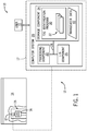
- FIG. 1 shows an illustrative environment 10 including an apparatus 12 and a (reciprocal motion) compressor 14 according to various embodiments of the invention.
- Environment 10 further includes at least one computing device (computer system 20), which includes a top-dead-center (TDC) identification program 30, which makes computer system 20 operable to determine a TDC of one or more pistons within the compressor by performing a process described herein.
- TDC top-dead-center
- a portion of the compressor 14 is shown in a cut-away view to illustrate one compressor cylinder 15 housing a piston 16. Also shown, along a sidewall of the cylinder 15, is a pressure transducer 17, which can be mounted in a conventional manner along the cylinder 15.
- the pressure transducer 17 can include any conventional pressure transducer, e.g., a piezoelectric pressure transducer, capacitive pressure transducer, optical pressure transducer, resonant pressure transducer, thermal pressure transducer, etc.
- the pressure transducer 17 can be operably connected (or, "coupled") with the computer system 20, e.g., via wireless and/or hard-wired means (connection shown via dashed line).
- the pressure transducer 17 and the computer system 20 are connected via a hard-wired connection, at least until the computer system 20 extracts at least one revolution of data to determine a TDC position of the piston 16 (described further herein).
- the pressure transducer 17 includes at least one component of the computer system 20, such that one or more processes performed by the computer system 20 can be performed at the pressure transducer 17 (or in the computer system 20 physically coupled to the transducer 17).
- FIG. 1 shows this embodiment in phantom, where at least one component of the computer system 20 is contained within the pressure transducer 17.
- Various embodiments of the invention are directed toward the apparatus 12, which includes the computer system 20 coupled with the pressure transducer 17.
- Various other embodiments are directed toward the computer system 20, which can obtain data, e.g., from the pressure transducer 17, and perform processes using that data to determine a top-dead-center (TDC) position of the piston 16 within the compressor cylinder 15.
- TDC top-dead-center
- Various other embodiments include methods and computer program products which can include functions performed by a computing device, e.g., computer system 20.
- Computer system 20 is shown including a processing component 22 (e.g., one or more processors), a storage component 24 (e.g., a storage hierarchy), an input/output (I/O) component 26 (e.g., one or more I/O interfaces and/or devices), and a communications pathway 28.
- processing component 22 executes program code, such as TDC identification program 30, which is at least partially fixed in storage component 24. While executing program code, processing component 22 can process data, which can result in reading and/or writing transformed data from/to storage component 24 and/or I/O component 26 for further processing.
- Pathway 28 provides a communications link between each of the components in computer system 20.
- I/O component 26 can comprise one or more human I/O devices, which enable a human user 13 to interact with computer system 20 and/or one or more communications devices to enable a system user 13 to communicate with computer system 20 using any type of communications link.
- TDC identification program 30 can manage a set of interfaces (e.g., graphical user interface(s), application program interface, and/or the like) that enable human and/or system users 13 to interact with TDC identification program 30. Further, TDC identification program 30 can manage (e.g., store, retrieve, create, manipulate, organize, present, etc.) the data, such as transducer data 40, using any solution.
- transducer data 40 can include data gathered and/or transformed by a pressure transducer (e.g., transducer 17).
- that transducer data 40 can indicate pressure fluctuations inside a compressor cylinder (e.g., cylinder 15), and in some cases, the transducer data 40 can include an asynchronous waveform transformation of pressure fluctuation data.
- the asynchronous waveform can include a series of uniformly spaced data points, which indicate pressure fluctuation data obtained continuously from the cylinder 15.
- computer system 20 can comprise one or more general purpose computing articles of manufacture (e.g., computing devices) capable of executing program code, such as TDC identification program 30, installed thereon.
- program code means any collection of instructions, in any language, code or notation, that cause a computing device having an information processing capability to perform a particular action either directly or after any combination of the following: (a) conversion to another language, code or notation; (b) reproduction in a different material form; and/or (c) decompression.
- TDC identification program 30 can be embodied as any combination of system software and/or application software.
- TDC identification program 30 can be implemented using a set of modules 32.
- a module 32 can enable computer system 20 to perform a set of tasks used by TDC identification program 30, and can be separately developed and/or implemented apart from other portions of TDC identification program 30.
- the term "component” means any configuration of hardware, with or without software, which implements the functionality described in conjunction therewith using any solution, while the term “module” means program code that enables a computer system 20 to implement the actions described in conjunction therewith using any solution.
- a module is a substantial portion of a component that implements the actions. Regardless, it is understood that two or more components, modules, and/or systems may share some/all of their respective hardware and/or software. Further, it is understood that some of the functionality discussed herein may not be implemented or additional functionality may be included as part of computer system 20.
- each computing device can have only a portion of TDC identification program 30 fixed thereon (e.g., one or more modules 32).
- TDC identification program 30 are only representative of various possible equivalent computer systems that may perform a process described herein.
- the functionality provided by computer system 20 and TDC identification program 30 can be at least partially implemented by one or more computing devices that include any combination of general and/or specific purpose hardware with or without program code.
- the hardware and program code, if included, can be created using standard engineering and programming techniques, respectively.
- computer system 20 when computer system 20 includes multiple computing devices, the computing devices can communicate over any type of communications link. Further, while performing a process described herein, computer system 20 can communicate with one or more other computer systems using any type of communications link.
- the communications link can comprise any combination of various types of optical fiber, wired, and/or wireless links; comprise any combination of one or more types of networks; and/or utilize any combination of various types of transmission techniques and protocols.
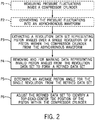
- FIG. 2 illustrates a flow chart depicting general processes which can be performed according to various embodiments of the invention. In some cases, these processes are described with reference to the environment 10 of FIG. 1 , however, it is understood that various processes can be performed in accordance with other environments and components not specifically depicted. These processes can be performed in the order shown, or in any other order to perform the functions of the invention described herein. Certain processes are illustrated as not necessarily being included in all embodiments by dashed lines. For example, preliminary processes P1 and P2 can be performed according to various embodiments described herein (e.g., those embodiments employing a pressure transducer 17 to gather pressure fluctuation data and convert that data to an asynchronous waveform). However, in various embodiments, an asynchronous waveforms is obtained, e.g., by at least one computing device, without requiring the measurement and conversion processes in P1-P2. As shown, various methods can include:
- This process P6 can include graphically displacing (shifting) the refined data set along the time domain such that the first value in the refined data set matches the determined TDC value.
- FIG. 3 depicts an example flow diagram including processes in extracting a single revolution of data (e.g., revolution data set) from the asynchronous waveform according to some embodiments, as described with reference to Process P3 in FIG. 2 . As shown, this process can include:
- process P311 includes setting indexStart equal to the index.
- Process P312 includes increasing the crossing values (crossings++), and setting the trigger to inactive.
- Process P313 includes: increase the index (index++). This Process P313 also follows Process P312.
- Process P316 Remove all points from the waveform outside of indexStart and indexStop, thereby reducing the asynchronous waveform data set to the revolution data set corresponding to the pressure fluctuations of one revolution (e.g., cycle) of the piston.
- the Process P3 utilizes crossings of the pressure fluctuation waveform relative to the average of the sample asynchronous waveform to extract the revolution data set.
- the graphical depiction adjacent Process P316 in FIG. 3 illustrates a snapshot of a single revolution of data about a piston within a compressor cylinder. As discussed herein, the graphical depiction adjacent Process P316 in FIG. 3 may be referred to as the extracted data set or the revolution data set.
- FIGS. 3-5 and 8 can be performed successively, simultaneously, or completely independently according to various embodiments of the invention. Linkage between these process flows (as illustrated by connecting nodes (1), (2) (3)) is shown merely for illustrative purposes.
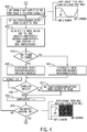
- FIG. 4 depicts an example flow diagram including processes in identifying and excluding piston angles based upon a compression ratio of the single revolution of the piston 16 within the compressor cylinder 15, according to some embodiments, as described with reference to Process 4 in FIG. 2 . As shown, this process can include:
- the process can proceed to identifying and excluding piston angles from further consideration as the TDC position based upon a volumetric efficiency of the single revolution of the piston within the compressor cylinder ( FIG. 5 ). As shown adjacent node (2) in FIGS. 4 and 5 , a portion of the sample data indicated in black in the graphical depiction was found invalid according to the processes illustrated in FIG. 4 .
- FIG. 5 depicts an example flow diagram including processes in identifying and excluding piston angles based upon a volumetric efficiency of the single revolution of the piston 16 within the compressor cylinder 15, according to some embodiments, as described with reference to Process 4 in FIG. 2 .
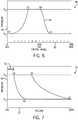
- FIG. 6 depicts an idealized compression cycle 48 of the pressure 50 within the cylinder 15 with respect to piston angle 52 during a revolution (e.g., cycle) of the piston 16.
- the waveform 54 illustrates the pressure 50 corresponding to each piston angle 52 of the revolution data set. While the illustrated compression cycle 48 of FIG. 6 shows 1000 piston angles 52 (e.g., 0 to 999) of the waveform 54, it may be appreciated that some embodiments may have greater or fewer piston angles per revolution data set.
- the pressure 50 may be at or near the suction pressure (P S ).
- P S suction pressure
- the pressure 50 may increase to the discharge pressure (P D ).
- the BDC position of the piston 16 within the cylinder 15 is opposite the TDC position, corresponding to the piston angle offset between the BDC position and the TDC position of half the quantity of the piston angles in the revolution data set.
- Reference ( 2 ) indicates the piston angle corresponding to when the discharge valve of the cylinder 15 opens to permit the release of the compressed fluid.
- Reference ( 4 ) indicates the piston angle corresponding to when the suction valve of the cylinder 15 opens to permit the intake of the fluid to be compressed between points ( 1 ) and ( 3 ) of the next cycle .
- the idealized compression cycle 48 illustrates references ( 2 ) and ( 3 ), and the points therebetween at the same discharge pressure P D , sampled pressure fluctuations may vary at pressures approximate (e.g., within 5% or less) of the discharge pressure P D .
- sampled pressure fluctuations may vary at pressures approximate (e.g., within 5% or less) of the suction pressure P S .
- FIG. 7 depicts an idealized pressure-volume diagram 70 of the pressure 50 within the cylinder 15 with respect to volume 72 of the cylinder 15 during a revolution (e.g., cycle) of the piston 16.
- the pressure 50 may be at or near the suction pressure (Ps) and the volume is at a maximum value.
- the piston 16 moves from the BDC position ( 1 ) toward the TDC position, as shown by reference ( 3 ).
- the volume decreases and the pressure increases from ( 1 ) to ( 2 ), then the discharge valve opens to enable the release of the compressed fluid at the discharge pressure P D as the volume decreases to the minimum value at TDC position ( 3 ).
- Reference ( 4 ) indicates the pressure at which the suction valve of the cylinder 15 opens to permit the intake of the fluid to be compressed between points ( 1 ) and ( 3 ) of the next cycle .
- the volume of the cylinder 15 when the piston 16 is at the TDC position ( 3 ) is the clearance volume (CL).
- Some measures of the volumetric efficiency of a compressor cylinder include, but are not limited to the suction volumetric efficiency (e.g., suction VE, VEs) and the discharge volumetric efficiency (e.g., discharge VE, VE D ).
- the suction VE may be defined in terms of the clearance volume CL, the discharge pressure P D , the suction pressure P S , and the isentropic volume exponent k, as shown in Equation 3 below.
- VE S 1 ⁇ CL P D / P S 1 / k ⁇ 1
- the discharge VE may be defined from the suction VE as shown here in Equation 4:
- VE D VE S / P D / P S 1 / k
- the discharge VE and the suction VE may be determined using the discharge pressure P D and the suction pressure P S without using the volume corresponding to each pressure.
- the pressure within the cylinder 15 at the TDC is the discharge pressure P D
- the pressure within the cylinder 15 at the BDC is the suction pressure P S .
- values for the discharge VE and the suction VE may be evaluated for each piston angle of the revolution data set and/or each piston angle of the revolution data set that has yet to be determined as an invalid piston angle. For example, a first pressure data point (e.g., the pressure data point at the first piston angle 0: P d0 ) is selected for evaluation as if the first pressure data point corresponds to the TDC position.
- This first pressure data point is evaluated as the pressure at V 3 according to Equations 1 and 2 above.
- a second pressure data point (e.g., the pressure data point at the middle piston angle 500: P D500 ) is selected for evaluation as if the second pressure data point corresponds to the BDC position.
- the piston angle of the second pressure data point is offset from the piston angle of the first pressure data point by half the length of the revolution data set.
- This second pressure data point is evaluated as the pressure at V 1 according to Equations 1 and 2 above.
- a third pressure data point of the revolution data set is determined for evaluation as the pressure at V 4 .
- This third pressure data point is determined by locating the next pressure data point in the revolution data set after the second pressure data point (e.g., the possible BDC position) with a value greater than the first pressure data point.
- the suction VE may be determined based on Equation 1 above where the piston angles (e.g., indices) of the second, third, and first pressure data points are used respectively in lieu of volumes for V 1 , V 4 , and V 3 in Equation 1.
- a fourth pressure data point of the revolution data set is determined for evaluation as the pressure at V 2 .
- This fourth pressure data point is determined by locating the next pressure data point in the revolution data set after the first pressure data point (e.g., the possible TDC position) with a value less than the second pressure data point.
- the discharge VE may be determined based on Equation 2 above where the piston angles (e.g., indices) of the fourth, first, and second pressure data points are used respectively in lieu of volumes for V 2 , V 3 , and V 1 in Equation 2.
- the process of identifying and excluding piston angles based upon a volumetric efficiency can include the following:
- Process P509 increase sample offset (SampleOffset++), thereby skipping piston angles previously deemed to be invalid as the possible TDC piston angle; If No, proceed to Decision D503: Is suction VE greater than a threshold (e.g., 0.20)?
- the suction VE threshold may be based on analyses of the suction VE evaluation of revolution data sets with a known TDC piston angle.
- Process P504 Set ValidTDCIndex (SampleOffset) array element to false, thereby evaluating the piston angle as an invalid piston angle; If Yes (and if No, after Process P504), proceed to Decision D505: Is discharge VE greater than a threshold (e.g., 0.10)?
- the discharge VE threshold may be based on analyses of the discharge VE evaluation of revolution data sets with a known TDC piston angle.
- decision D510 includes: Is SampleOffset greater than waveform length?
- the process can proceed to identifying and excluding piston angles based upon a clearance volume of the single revolution of the piston within the compressor cylinder ( FIG. 8 ). As shown adjacent node (3), a portion of the sample data indicated in black in the graphical depiction was found invalid according to the processes illustrated in FIG. 5 .
- FIG. 8 depicts an example flow diagram including processes in identifying and excluding piston angles based upon a clearance volume of the single revolution of the piston 16 within the compressor cylinder 15, according to some embodiments, as described with reference to Process 4 in FIG. 2 .
- this process can include: Process P600: Calculate suction clearance volume (CV S ) and discharge clearance volume (CV D ) for all possible piston angles of the revolution data set.
- VE S suction volumetric efficiency
- VE D discharge volumetric efficiency
- Process P601 Set variable SampleOffset to the first value in the array (waveform), which is typically a value of zero (0).
- Process P601 is illustrated with a graphical depiction showing samples per revolution data set, where the color white indicates a possibly valid piston angle, and black indicates an invalid piston angle of the revolution data set.
- Process P609 Increase sample offset (SampleOffset++), thereby evaluating the piston angle as an invalid piston angle; If No, proceed to Decision D603: Is the suction CV less than zero (0)?
- the suction CV threshold may be based on analyses of the suction CV evaluation of revolution data sets with a known TDC piston angle.
- Process P604 set ValidTDCIndex (SampleOffset) array element to false, thereby evaluating the piston angle as an invalid piston angle; If No (and if Yes, after Process P604), proceed to Decision D605: Is the discharge CV less than zero (0)?
- the discharge CV threshold may be based on analyses of the discharge CV evaluation of revolution data sets with a known TDC piston angle.
- Process P606 Set ValidTDCIndex (SampleOffset) array element to false), thereby evaluating the piston angle as an invalid piston angle; If No (and if Yes, after Process P606), proceed to Decision D607: Is (Suction CV/Discharge CV) between a threshold range (e.g., 0.95 and 1.05)?
- a threshold range e.g. 0.95 and 1.05
- Process P608 Set ValidTDCIndex (SampleOffset) array element to false; If Yes (and if No, after process P608), proceed to Process P609: Increase sample offset (SampleOffset++).
- Process P612 Re-index (adjust) the waveform array so that the piston angle determined to be the index of the TDC is the first element in the waveform and revolution data set.
- computer system 20 can obtain transducer data 40 using any solution.
- computer system 20 can generate and/or be used to generate transducer data 40, retrieve transducer data 40 from one or more data stores, receive transducer data 40 from another system, and/or the like.
- the invention provides a computer program fixed in at least one computer-readable medium, which when executed, enables a computer system to determine a top-dead-center location in a reciprocating compressor.
- the computer-readable medium includes program code, such as TDC identification program 30 ( FIG. 1 ), which enables a computer system to implement some or all of a process described herein.
- the term "computer-readable medium” comprises one or more of any type of tangible medium of expression, now known or later developed, from which a copy of the program code can be perceived, reproduced, or otherwise communicated by a computing device.
- the computer-readable medium can comprise: one or more portable storage articles of manufacture; one or more memory/storage components of a computing device; paper; and/or the like.
- the invention provides a method of providing a copy of program code, such as TDC identification program 30 ( FIG. 1 ), which enables a computer system to implement some or all of a process described herein.
- a computer system can process a copy of the program code to generate and transmit, for reception at a second, distinct location, a set of data signals that has one or more of its characteristics set and/or changed in such a manner as to encode a copy of the program code in the set of data signals.
- an embodiment of the invention provides a method of acquiring a copy of the program code, which includes a computer system receiving the set of data signals described herein, and translating the set of data signals into a copy of the computer program fixed in at least one computer-readable medium. In either case, the set of data signals can be transmitted/received using any type of communications link.
- the invention provides a method of generating TDC identification program.
- a computer system such as computer system 20 ( FIG. 1 ) can be obtained (e.g., created, maintained, made available, etc.) and one or more components for performing a process described herein can be obtained (e.g., created, purchased, used, modified, etc.) and deployed to the computer system.
- the deployment can comprise one or more of: (1) installing program code on a computing device; (2) adding one or more computing and/or I/O devices to the computer system; (3) incorporating and/or modifying the computer system to enable it to perform a process described herein; and/or the like.
- the technical effect of the TDC identification program 30 shown and described herein is to identify a top-dead-center position of a piston within a cylinder of a reciprocating compressor based at least in part on pressure fluctuation data, such as from the pressure transducer 17 of the cylinder 15 of the compressor.
Landscapes
- Engineering & Computer Science (AREA)
- Mechanical Engineering (AREA)
- General Engineering & Computer Science (AREA)
- Computer Hardware Design (AREA)
- Control Of Positive-Displacement Pumps (AREA)
Applications Claiming Priority (1)
| Application Number | Priority Date | Filing Date | Title |
|---|---|---|---|
| US15/134,150 US10323937B2 (en) | 2013-01-23 | 2016-04-20 | System and method of determining top-dead-center (TDC) of reciprocating compressor |
Publications (2)
| Publication Number | Publication Date |
|---|---|
| EP3236072A1 EP3236072A1 (en) | 2017-10-25 |
| EP3236072B1 true EP3236072B1 (en) | 2020-11-04 |
Family
ID=57354187
Family Applications (1)
| Application Number | Title | Priority Date | Filing Date |
|---|---|---|---|
| EP16199469.4A Active EP3236072B1 (en) | 2016-04-20 | 2016-11-18 | System and method of determining top-dead-center (tdc) of reciprocating compressor |
Country Status (2)
| Country | Link |
|---|---|
| EP (1) | EP3236072B1 (da) |
| DK (1) | DK3236072T3 (da) |
Families Citing this family (2)
| Publication number | Priority date | Publication date | Assignee | Title |
|---|---|---|---|---|
| US12560355B2 (en) | 2021-07-28 | 2026-02-24 | Carrier Corporation | Duct mounted filtering apparatus |
| US12398926B2 (en) | 2021-08-04 | 2025-08-26 | Carrier Corporation | Economizer injection in a reciprocating compressor |
Family Cites Families (1)
| Publication number | Priority date | Publication date | Assignee | Title |
|---|---|---|---|---|
| US20140205471A1 (en) * | 2013-01-23 | 2014-07-24 | General Electric Company | Determining top-dead-center (tdc) of reciprocating compressor |
-
2016
- 2016-11-18 EP EP16199469.4A patent/EP3236072B1/en active Active
- 2016-11-18 DK DK16199469.4T patent/DK3236072T3/da active
Non-Patent Citations (1)
| Title |
|---|
| None * |
Also Published As
| Publication number | Publication date |
|---|---|
| DK3236072T3 (da) | 2021-01-18 |
| EP3236072A1 (en) | 2017-10-25 |
Similar Documents
| Publication | Publication Date | Title |
|---|---|---|
| US11579122B2 (en) | Automatic mechanical systems diagnosis | |
| US10808864B2 (en) | System and method for controlling a field device | |
| US7056097B2 (en) | System and method for monitoring the mechanical condition of a reciprocating compressor | |
| FI128394B (en) | Monitoring device and method for determining operating health of pressure medium operated device | |
| US8147211B2 (en) | Method and system for monitoring a reciprocating compressor valve | |
| EP3236072A1 (en) | System and method of determining top-dead-center (tdc) of reciprocating compressor | |
| JP2014141967A (ja) | 往復圧縮機の上死点(tdc)の特定 | |
| CN107917069B (zh) | 往复式压缩机流量感测 | |
| CA2916067A1 (en) | Method and apparatus for real-time fluid compressibility measurements | |
| CN119782926A (zh) | 一种压缩机运行状态监测方法及系统 | |
| CN110410057B (zh) | 抽油机井光杆悬点死点的检测方法及系统 | |
| US10323937B2 (en) | System and method of determining top-dead-center (TDC) of reciprocating compressor | |
| CA3116804A1 (en) | System and method for operating downhole pump | |
| CN118427700A (zh) | 应用于气动球阀的自检系统和方法 | |
| WO2018106961A1 (en) | System, method and apparatus for pulsating pressure measurement | |
| CN100453809C (zh) | 监控往复式压缩机的方法和系统 | |
| CN110500268B (zh) | 一种基于示功图的往复式压缩机反向角检测系统 | |
| DK3130977T3 (da) | Analyse af maskinedriftsparametre | |
| WO2026074070A1 (en) | A method for determining an operating condition of a reciprocating compressor | |
| CN121298304B (zh) | 压缩机性能预测方法、装置、电子设备及存储介质 | |
| CN121324035B (zh) | 离心制冷机的性能预测方法和装置、电子设备及存储介质 | |
| CN115681115B (zh) | 往复压缩机故障检测方法和装置 | |
| Chesnes et al. | A Feature Extraction Method for Prognostic Health Assessment of Gas Compressor Valves | |
| CN121897567A (zh) | 一种用于压裂泵液力端密封状态在线识别的控制系统 |
Legal Events
| Date | Code | Title | Description |
|---|---|---|---|
| PUAI | Public reference made under article 153(3) epc to a published international application that has entered the european phase |
Free format text: ORIGINAL CODE: 0009012 |
|
| STAA | Information on the status of an ep patent application or granted ep patent |
Free format text: STATUS: THE APPLICATION HAS BEEN PUBLISHED |
|
| AK | Designated contracting states |
Kind code of ref document: A1 Designated state(s): AL AT BE BG CH CY CZ DE DK EE ES FI FR GB GR HR HU IE IS IT LI LT LU LV MC MK MT NL NO PL PT RO RS SE SI SK SM TR |
|
| AX | Request for extension of the european patent |
Extension state: BA ME |
|
| STAA | Information on the status of an ep patent application or granted ep patent |
Free format text: STATUS: REQUEST FOR EXAMINATION WAS MADE |
|
| 17P | Request for examination filed |
Effective date: 20180425 |
|
| RBV | Designated contracting states (corrected) |
Designated state(s): AL AT BE BG CH CY CZ DE DK EE ES FI FR GB GR HR HU IE IS IT LI LT LU LV MC MK MT NL NO PL PT RO RS SE SI SK SM TR |
|
| STAA | Information on the status of an ep patent application or granted ep patent |
Free format text: STATUS: EXAMINATION IS IN PROGRESS |
|
| 17Q | First examination report despatched |
Effective date: 20191015 |
|
| GRAP | Despatch of communication of intention to grant a patent |
Free format text: ORIGINAL CODE: EPIDOSNIGR1 |
|
| STAA | Information on the status of an ep patent application or granted ep patent |
Free format text: STATUS: GRANT OF PATENT IS INTENDED |
|
| INTG | Intention to grant announced |
Effective date: 20200528 |
|
| GRAS | Grant fee paid |
Free format text: ORIGINAL CODE: EPIDOSNIGR3 |
|
| GRAA | (expected) grant |
Free format text: ORIGINAL CODE: 0009210 |
|
| STAA | Information on the status of an ep patent application or granted ep patent |
Free format text: STATUS: THE PATENT HAS BEEN GRANTED |
|
| AK | Designated contracting states |
Kind code of ref document: B1 Designated state(s): AL AT BE BG CH CY CZ DE DK EE ES FI FR GB GR HR HU IE IS IT LI LT LU LV MC MK MT NL NO PL PT RO RS SE SI SK SM TR |
|
| REG | Reference to a national code |
Ref country code: GB Ref legal event code: FG4D |
|
| REG | Reference to a national code |
Ref country code: CH Ref legal event code: EP |
|
| REG | Reference to a national code |
Ref country code: AT Ref legal event code: REF Ref document number: 1331165 Country of ref document: AT Kind code of ref document: T Effective date: 20201115 |
|
| REG | Reference to a national code |
Ref country code: IE Ref legal event code: FG4D |
|
| REG | Reference to a national code |
Ref country code: DE Ref legal event code: R096 Ref document number: 602016047053 Country of ref document: DE |
|
| REG | Reference to a national code |
Ref country code: DK Ref legal event code: T3 Effective date: 20210115 |
|
| REG | Reference to a national code |
Ref country code: SE Ref legal event code: TRGR |
|
| REG | Reference to a national code |
Ref country code: NL Ref legal event code: MP Effective date: 20201104 |
|
| REG | Reference to a national code |
Ref country code: AT Ref legal event code: MK05 Ref document number: 1331165 Country of ref document: AT Kind code of ref document: T Effective date: 20201104 |
|
| PG25 | Lapsed in a contracting state [announced via postgrant information from national office to epo] |
Ref country code: GR Free format text: LAPSE BECAUSE OF FAILURE TO SUBMIT A TRANSLATION OF THE DESCRIPTION OR TO PAY THE FEE WITHIN THE PRESCRIBED TIME-LIMIT Effective date: 20210205 Ref country code: FI Free format text: LAPSE BECAUSE OF FAILURE TO SUBMIT A TRANSLATION OF THE DESCRIPTION OR TO PAY THE FEE WITHIN THE PRESCRIBED TIME-LIMIT Effective date: 20201104 Ref country code: RS Free format text: LAPSE BECAUSE OF FAILURE TO SUBMIT A TRANSLATION OF THE DESCRIPTION OR TO PAY THE FEE WITHIN THE PRESCRIBED TIME-LIMIT Effective date: 20201104 Ref country code: PT Free format text: LAPSE BECAUSE OF FAILURE TO SUBMIT A TRANSLATION OF THE DESCRIPTION OR TO PAY THE FEE WITHIN THE PRESCRIBED TIME-LIMIT Effective date: 20210304 Ref country code: NO Free format text: LAPSE BECAUSE OF FAILURE TO SUBMIT A TRANSLATION OF THE DESCRIPTION OR TO PAY THE FEE WITHIN THE PRESCRIBED TIME-LIMIT Effective date: 20210204 |
|
| PG25 | Lapsed in a contracting state [announced via postgrant information from national office to epo] |
Ref country code: AT Free format text: LAPSE BECAUSE OF FAILURE TO SUBMIT A TRANSLATION OF THE DESCRIPTION OR TO PAY THE FEE WITHIN THE PRESCRIBED TIME-LIMIT Effective date: 20201104 Ref country code: ES Free format text: LAPSE BECAUSE OF FAILURE TO SUBMIT A TRANSLATION OF THE DESCRIPTION OR TO PAY THE FEE WITHIN THE PRESCRIBED TIME-LIMIT Effective date: 20201104 Ref country code: PL Free format text: LAPSE BECAUSE OF FAILURE TO SUBMIT A TRANSLATION OF THE DESCRIPTION OR TO PAY THE FEE WITHIN THE PRESCRIBED TIME-LIMIT Effective date: 20201104 Ref country code: IS Free format text: LAPSE BECAUSE OF FAILURE TO SUBMIT A TRANSLATION OF THE DESCRIPTION OR TO PAY THE FEE WITHIN THE PRESCRIBED TIME-LIMIT Effective date: 20210304 Ref country code: LV Free format text: LAPSE BECAUSE OF FAILURE TO SUBMIT A TRANSLATION OF THE DESCRIPTION OR TO PAY THE FEE WITHIN THE PRESCRIBED TIME-LIMIT Effective date: 20201104 Ref country code: BG Free format text: LAPSE BECAUSE OF FAILURE TO SUBMIT A TRANSLATION OF THE DESCRIPTION OR TO PAY THE FEE WITHIN THE PRESCRIBED TIME-LIMIT Effective date: 20210204 |
|
| REG | Reference to a national code |
Ref country code: LT Ref legal event code: MG9D |
|
| PG25 | Lapsed in a contracting state [announced via postgrant information from national office to epo] |
Ref country code: HR Free format text: LAPSE BECAUSE OF FAILURE TO SUBMIT A TRANSLATION OF THE DESCRIPTION OR TO PAY THE FEE WITHIN THE PRESCRIBED TIME-LIMIT Effective date: 20201104 |
|
| PG25 | Lapsed in a contracting state [announced via postgrant information from national office to epo] |
Ref country code: LU Free format text: LAPSE BECAUSE OF NON-PAYMENT OF DUE FEES Effective date: 20201118 Ref country code: LT Free format text: LAPSE BECAUSE OF FAILURE TO SUBMIT A TRANSLATION OF THE DESCRIPTION OR TO PAY THE FEE WITHIN THE PRESCRIBED TIME-LIMIT Effective date: 20201104 Ref country code: SM Free format text: LAPSE BECAUSE OF FAILURE TO SUBMIT A TRANSLATION OF THE DESCRIPTION OR TO PAY THE FEE WITHIN THE PRESCRIBED TIME-LIMIT Effective date: 20201104 Ref country code: CZ Free format text: LAPSE BECAUSE OF FAILURE TO SUBMIT A TRANSLATION OF THE DESCRIPTION OR TO PAY THE FEE WITHIN THE PRESCRIBED TIME-LIMIT Effective date: 20201104 Ref country code: EE Free format text: LAPSE BECAUSE OF FAILURE TO SUBMIT A TRANSLATION OF THE DESCRIPTION OR TO PAY THE FEE WITHIN THE PRESCRIBED TIME-LIMIT Effective date: 20201104 Ref country code: SK Free format text: LAPSE BECAUSE OF FAILURE TO SUBMIT A TRANSLATION OF THE DESCRIPTION OR TO PAY THE FEE WITHIN THE PRESCRIBED TIME-LIMIT Effective date: 20201104 Ref country code: RO Free format text: LAPSE BECAUSE OF FAILURE TO SUBMIT A TRANSLATION OF THE DESCRIPTION OR TO PAY THE FEE WITHIN THE PRESCRIBED TIME-LIMIT Effective date: 20201104 |
|
| REG | Reference to a national code |
Ref country code: DE Ref legal event code: R097 Ref document number: 602016047053 Country of ref document: DE |
|
| REG | Reference to a national code |
Ref country code: BE Ref legal event code: MM Effective date: 20201130 |
|
| PG25 | Lapsed in a contracting state [announced via postgrant information from national office to epo] |
Ref country code: MC Free format text: LAPSE BECAUSE OF FAILURE TO SUBMIT A TRANSLATION OF THE DESCRIPTION OR TO PAY THE FEE WITHIN THE PRESCRIBED TIME-LIMIT Effective date: 20201104 |
|
| PLBE | No opposition filed within time limit |
Free format text: ORIGINAL CODE: 0009261 |
|
| STAA | Information on the status of an ep patent application or granted ep patent |
Free format text: STATUS: NO OPPOSITION FILED WITHIN TIME LIMIT |
|
| 26N | No opposition filed |
Effective date: 20210805 |
|
| PG25 | Lapsed in a contracting state [announced via postgrant information from national office to epo] |
Ref country code: AL Free format text: LAPSE BECAUSE OF FAILURE TO SUBMIT A TRANSLATION OF THE DESCRIPTION OR TO PAY THE FEE WITHIN THE PRESCRIBED TIME-LIMIT Effective date: 20201104 Ref country code: IT Free format text: LAPSE BECAUSE OF FAILURE TO SUBMIT A TRANSLATION OF THE DESCRIPTION OR TO PAY THE FEE WITHIN THE PRESCRIBED TIME-LIMIT Effective date: 20201104 Ref country code: IE Free format text: LAPSE BECAUSE OF NON-PAYMENT OF DUE FEES Effective date: 20201118 Ref country code: NL Free format text: LAPSE BECAUSE OF FAILURE TO SUBMIT A TRANSLATION OF THE DESCRIPTION OR TO PAY THE FEE WITHIN THE PRESCRIBED TIME-LIMIT Effective date: 20201104 Ref country code: FR Free format text: LAPSE BECAUSE OF NON-PAYMENT OF DUE FEES Effective date: 20210104 |
|
| PG25 | Lapsed in a contracting state [announced via postgrant information from national office to epo] |
Ref country code: SI Free format text: LAPSE BECAUSE OF FAILURE TO SUBMIT A TRANSLATION OF THE DESCRIPTION OR TO PAY THE FEE WITHIN THE PRESCRIBED TIME-LIMIT Effective date: 20201104 |
|
| PG25 | Lapsed in a contracting state [announced via postgrant information from national office to epo] |
Ref country code: IS Free format text: LAPSE BECAUSE OF FAILURE TO SUBMIT A TRANSLATION OF THE DESCRIPTION OR TO PAY THE FEE WITHIN THE PRESCRIBED TIME-LIMIT Effective date: 20210304 Ref country code: TR Free format text: LAPSE BECAUSE OF FAILURE TO SUBMIT A TRANSLATION OF THE DESCRIPTION OR TO PAY THE FEE WITHIN THE PRESCRIBED TIME-LIMIT Effective date: 20201104 Ref country code: MT Free format text: LAPSE BECAUSE OF FAILURE TO SUBMIT A TRANSLATION OF THE DESCRIPTION OR TO PAY THE FEE WITHIN THE PRESCRIBED TIME-LIMIT Effective date: 20201104 Ref country code: CY Free format text: LAPSE BECAUSE OF FAILURE TO SUBMIT A TRANSLATION OF THE DESCRIPTION OR TO PAY THE FEE WITHIN THE PRESCRIBED TIME-LIMIT Effective date: 20201104 |
|
| PG25 | Lapsed in a contracting state [announced via postgrant information from national office to epo] |
Ref country code: MK Free format text: LAPSE BECAUSE OF FAILURE TO SUBMIT A TRANSLATION OF THE DESCRIPTION OR TO PAY THE FEE WITHIN THE PRESCRIBED TIME-LIMIT Effective date: 20201104 |
|
| PG25 | Lapsed in a contracting state [announced via postgrant information from national office to epo] |
Ref country code: BE Free format text: LAPSE BECAUSE OF NON-PAYMENT OF DUE FEES Effective date: 20201130 |
|
| P01 | Opt-out of the competence of the unified patent court (upc) registered |
Effective date: 20230526 |
|
| REG | Reference to a national code |
Ref country code: CH Ref legal event code: U11 Free format text: ST27 STATUS EVENT CODE: U-0-0-U10-U11 (AS PROVIDED BY THE NATIONAL OFFICE) Effective date: 20251201 |
|
| PGFP | Annual fee paid to national office [announced via postgrant information from national office to epo] |
Ref country code: DE Payment date: 20251022 Year of fee payment: 10 |
|
| PGFP | Annual fee paid to national office [announced via postgrant information from national office to epo] |
Ref country code: GB Payment date: 20251022 Year of fee payment: 10 |
|
| PGFP | Annual fee paid to national office [announced via postgrant information from national office to epo] |
Ref country code: DK Payment date: 20251022 Year of fee payment: 10 |
|
| PGFP | Annual fee paid to national office [announced via postgrant information from national office to epo] |
Ref country code: SE Payment date: 20251022 Year of fee payment: 10 Ref country code: CH Payment date: 20251201 Year of fee payment: 10 |