EP3236100A1 - Support de garniture de frein pour un véhicule sur rails - Google Patents
Support de garniture de frein pour un véhicule sur rails Download PDFInfo
- Publication number
- EP3236100A1 EP3236100A1 EP17164936.1A EP17164936A EP3236100A1 EP 3236100 A1 EP3236100 A1 EP 3236100A1 EP 17164936 A EP17164936 A EP 17164936A EP 3236100 A1 EP3236100 A1 EP 3236100A1
- Authority
- EP
- European Patent Office
- Prior art keywords
- brake pad
- pad holder
- eccentric shaft
- eccentric
- locking device
- Prior art date
- Legal status (The legal status is an assumption and is not a legal conclusion. Google has not performed a legal analysis and makes no representation as to the accuracy of the status listed.)
- Granted
Links
Images


Classifications
-
- F—MECHANICAL ENGINEERING; LIGHTING; HEATING; WEAPONS; BLASTING
- F16—ENGINEERING ELEMENTS AND UNITS; GENERAL MEASURES FOR PRODUCING AND MAINTAINING EFFECTIVE FUNCTIONING OF MACHINES OR INSTALLATIONS; THERMAL INSULATION IN GENERAL
- F16D—COUPLINGS FOR TRANSMITTING ROTATION; CLUTCHES; BRAKES
- F16D69/00—Friction linings; Attachment thereof; Selection of coacting friction substances or surfaces
- F16D69/04—Attachment of linings
- F16D69/0408—Attachment of linings specially adapted for plane linings
-
- F—MECHANICAL ENGINEERING; LIGHTING; HEATING; WEAPONS; BLASTING
- F16—ENGINEERING ELEMENTS AND UNITS; GENERAL MEASURES FOR PRODUCING AND MAINTAINING EFFECTIVE FUNCTIONING OF MACHINES OR INSTALLATIONS; THERMAL INSULATION IN GENERAL
- F16D—COUPLINGS FOR TRANSMITTING ROTATION; CLUTCHES; BRAKES
- F16D65/00—Parts or details
- F16D65/02—Braking members; Mounting thereof
- F16D65/04—Bands, shoes or pads; Pivots or supporting members therefor
- F16D65/092—Bands, shoes or pads; Pivots or supporting members therefor for axially-engaging brakes, e.g. disc brakes
- F16D65/095—Pivots or supporting members therefor
-
- B—PERFORMING OPERATIONS; TRANSPORTING
- B61—RAILWAYS
- B61H—BRAKES OR OTHER RETARDING DEVICES SPECIALLY ADAPTED FOR RAIL VEHICLES; ARRANGEMENT OR DISPOSITION THEREOF IN RAIL VEHICLES
- B61H5/00—Applications or arrangements of brakes with substantially radial braking surfaces pressed together in axial direction, e.g. disc brakes
-
- F—MECHANICAL ENGINEERING; LIGHTING; HEATING; WEAPONS; BLASTING
- F16—ENGINEERING ELEMENTS AND UNITS; GENERAL MEASURES FOR PRODUCING AND MAINTAINING EFFECTIVE FUNCTIONING OF MACHINES OR INSTALLATIONS; THERMAL INSULATION IN GENERAL
- F16D—COUPLINGS FOR TRANSMITTING ROTATION; CLUTCHES; BRAKES
- F16D65/00—Parts or details
- F16D65/02—Braking members; Mounting thereof
- F16D65/04—Bands, shoes or pads; Pivots or supporting members therefor
- F16D65/092—Bands, shoes or pads; Pivots or supporting members therefor for axially-engaging brakes, e.g. disc brakes
- F16D65/095—Pivots or supporting members therefor
- F16D65/097—Resilient means interposed between pads and supporting members or other brake parts
- F16D65/0971—Resilient means interposed between pads and supporting members or other brake parts transmitting brake actuation force, e.g. elements interposed between brake piston and pad
-
- F—MECHANICAL ENGINEERING; LIGHTING; HEATING; WEAPONS; BLASTING
- F16—ENGINEERING ELEMENTS AND UNITS; GENERAL MEASURES FOR PRODUCING AND MAINTAINING EFFECTIVE FUNCTIONING OF MACHINES OR INSTALLATIONS; THERMAL INSULATION IN GENERAL
- F16D—COUPLINGS FOR TRANSMITTING ROTATION; CLUTCHES; BRAKES
- F16D69/00—Friction linings; Attachment thereof; Selection of coacting friction substances or surfaces
- F16D69/04—Attachment of linings
- F16D2069/0425—Attachment methods or devices
Definitions
- the invention relates to a brake pad holder for a rail vehicle, comprising at least one locking device and a sliding rail extending in the direction of a brake pad holder longitudinal axis for receiving a brake pad.
- Brake pads for rail vehicles must securely lock brake pads, ie protect against unintended movements and loss. For this reason, locking devices are used. In addition to a corresponding level of safety, these must enable rapid replacement of brake linings over a long service life and be resistant to mechanical and thermal stresses or wear and other environmental influences. Individual components must be easily and quickly exchanged during maintenance and servicing. Furthermore, a locking device is to be able to compensate for a play between the brake pad and the brake pad holder even under the effect of thermal expansions, etc.
- the prior art describes, for example, the EP 2 587 086 B1 a locking device of a brake pad holder for a rail vehicle.
- the brake pad holder includes a slide rail with a dovetail portion in which a brake pad can be locked.
- On the brake pad holder in the region of the slide rail or on a bolt vertically aligned elastic means are arranged, which exert a vertical force on the brake pad to block it in the slide rail.
- the bolt is inserted in a lower portion of the brake pad holder in a transverse to a brake pad holder longitudinal axis guide rail and there is a locking of the brake pad due to a vertical force of the bolt on the brake pad.
- the bolt and the guide rail are designed, for example wedge-shaped.
- Said approach has in its known form the disadvantage that a tool is required for the introduction of the bolt in the guide rail. Furthermore, the vertically oriented, elastic means are particularly heavily loaded by the vertical components of contact forces between the brake pad and a brake disc. Furthermore, the elastic means are thermally heavily loaded by their arrangement in close proximity to the brake pad.
- the invention is therefore based on the object to provide a comparison with the prior art improved brake pad holder.
- this object is achieved with a brake pad holder of the type mentioned, in which the locking device has an eccentric shaft with an eccentric arranged on a first end face, a bushing connected to the brake pad holder and a spring, wherein the eccentric shaft is guided in the bushing in a manner and the spring is arranged in a manner coaxial with the eccentric shaft, that the eccentric forces against the brake pad and the brake pad holder.
- the eccentric shaft allows due to their mobility in the direction of an eccentric shaft longitudinal axis against the restoring effect of the spring an advantageous distance compensation between the brake pad and the brake pad holder.
- the play for example, influenced by different thermal expansions of these two components, between the brake pad and the brake pad holder is reduced. Consequently, wear and damage to one Friction brake system and disturbing noise emissions reduced in a favorable manner. Furthermore, no tools are required for locking and releasing the locking device.
- An advantageous embodiment is obtained if a helical groove is formed on the lateral surface of the eccentric shaft, and if a helical profile is provided as a mating contour to the helical groove on the inner circumferential surface of the socket.
- This measure causes a self-locking effect of the eccentric shaft in the socket due to the frictional contact between the helical groove and the helical profile.
- the movement in connection with the locking and releasing the locking device is characterized kinematically defined and unintentional movements of the eccentric shaft in the direction of the eccentric shaft longitudinal axis are difficult.
- the locking device comprises a low-wear sliding block and that a slotted guide is provided for its reception, when the sliding block has a support surface on which in a locked state of the Locking device of the brake pad is applied, when the sliding block has a contact surface on which rests in a locked state of the locking device of the eccentric, and when the sliding block has a recess into which engages in a locked state of the locking device of the eccentric.
- This measure reduces problems due to mechanical and thermal stresses as well as wear of the locking device.
- the sliding block is as compared to the eccentric and the eccentric shaft more mechanically and thermally loaded component made of a low-wear material and can be replaced quickly and inexpensively due to its design and its arrangement on the brake pad holder without much effort. The frequency of a complete replacement of the locking device is reduced.
- the slotted guide 23 is arranged in the lower region of the brake pad holder 1, below the slide rail 9.
- the guide surfaces 6 extend transversely to the slide rail 9, the contact surface 19 is aligned parallel thereto.
- the bushing 12 is likewise arranged below the slide rail 9, its longitudinal axis extending transversely to the brake pad holder longitudinal axis 8.
- the bush 12 is part of a locking device 7.
- the eccentric shaft 10 has on a first end face the eccentric 2, on a second end face a in Fig. 1 not, but in Fig. 3 shown flange 11.
- This comprises immediately adjacent to the first end face of the eccentric shaft 10, a first cylindrical part and immediately adjacent to the end face of the first cylindrical part a second cylindrical part with a larger diameter than the first cylindrical part.
- the center of the second cylindrical part lies on the projection of the end face circumference of the first cylindrical part.
- the first cylindrical part and the second cylindrical part do not protrude beyond the projection of the end surface circumference of the eccentric shaft 10.
- the sliding block 15 has a contact surface 16 for the Applying the eccentric 2 and, parallel to its base 18, a semi-cylindrical recess 17 for the engagement of the eccentric 2.
- the inner shell surface of the recess 17 is congruent with the mantle surface of the eccentric second
- the recess 17 is not in Fig. 1 , but in Fig. 4 shown.
- a bearing surface 4 is provided for a brake pad on the sliding block 15.
- the sliding block 15 is made of a high-strength, wear-resistant steel.
- the brake pad is inserted with a arranged on its back dovetail profile in the slide rail 9.
- the sliding block 15 is inserted with side surfaces 5 parallel to the arranged on the brake pad holder 1 guide surfaces 6 and with a base 18 parallel to the disposed on the brake pad holder 1 contact surface 19 and adjacent thereto in the slotted guide 23 of the brake pad holder 1.
- the support surface 4 has in the direction of the top of the brake pad holder 1, the contact surface 16 in the direction of the bottom, that is, the sleeve 12 faces.
- the eccentric shaft 10 is inserted into the bushing 12, wherein the eccentric shaft longitudinal axis 20 is coaxial with the longitudinal axis of the bush 12.
- the mantle surface of the eccentric shaft 10 is congruent with the inner circumferential surface of the bush 12.
- the spring 13 sets to a corresponding executed, in Fig. 2 shown bushing face 21 and it builds up on the spring force 22.
- the eccentric shaft 10 is rotated about the eccentric shaft longitudinal axis 20 until the first cylindrical part rests against the contact surface 16 and the second cylindrical part engages in the recess 17 on the sliding block.
- the eccentric shaft 10 is locked via the eccentric 2 in the sliding block 15.
- a vertical clamping force acts from the eccentric 2 forth on the support surface 4 of the sliding block 15 on the brake pad and locks it in the slide rail 9.
- the spring force 22 acts restoring in the direction of the Exzenterwellenl Kunststoffsachse 20 and presses the eccentric 2 in the recess 17 and the base 18th of the sliding block 15 to the contact surface 19 on the brake pad holder.
- Fig. 2 shows a Schrägriss the back of a first exemplary embodiment of a brake pad holder 1 according to the invention.
- a female end face 21 is shown.
- the content of Fig. 2 that of Fig. 1 is shown.
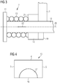
- Fig. 3 shows a detailed view of a first exemplary embodiment of a brake pad holder 1 according to the invention with a locking device 7 according to the invention, wherein a section of an eccentric shaft 10 with a flange 11, a spring 13 in a sectional view and a section of a socket 12 are shown.
- the spring 13 is designed as a cylindrical helical compression spring, but there are other variants conceivable according to the invention, such as disc springs, flat springs or torsion springs in a corresponding arrangement with respect to the eccentric shaft 10th
- the spring 13 is connected to the flange 11, arranged around the eccentric shaft 10 and extends coaxially thereto. It is shown an assembly state in which the spring 13 bears against a bushing end face 21, is thereby compressed and generates a spring force 22.
- Fig. 4 shows a sliding block 15 of the invention, as he used for in connection with the Fig. 1 and Fig. 2 described, the first embodiment of a brake pad holder 1 according to the invention is used.
- the sliding block 15 is shown as an elevation with projecting side surfaces 5. It comprises on its underside projecting a projecting surface 16 for a in the Fig. 1 and Fig. 2 shown eccentric 2 and on its top a projecting bearing surface 4 for a brake pad.
- a semi-cylindrical recess 17 is provided on the sliding block 15, the inner circumferential surface is congruent with the lateral surface of the eccentric 2.
- the eccentric 2 can be inserted into the recess 17 and locked as in connection with Fig. 1 described, the sliding block 15 on the brake pad holder 1.
- second embodiment of a brake pad holder 1 according to the invention different from Fig. 4 , provided on the sliding block 15 no recess 17.
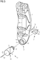
- FIG. 2 illustrates a perspective view of the rear side of a second, exemplary embodiment of a brake pad holder 1 according to the invention.
- FIG. In contrast to Fig. 2 has an eccentric shaft 10 a helical groove 3 and a socket 12 a Helix profile 14 on.
- the helical groove 3 is formed on the lateral surface of the eccentric shaft 10, the helical profile 14 on the inner circumferential surface of the sleeve 12th
- a sliding block 15 does not have the in Fig. 4 shown recess 17.
- the eccentric shaft 10 is screwed via a kinematically defined due to the helical groove 3 and the helical profile 14 movement in the socket 12.
- the process ends for this second, exemplary embodiment with the application of an eccentric 2 in a contact surface 16.
- the eccentric shaft 10 is due to the combined positive and form fit of the fit between the helical groove 3 and the helical profile 14 and due to a spring force 22 at a movement and a release of the sliding block 15 and the brake pad prevented.
- the illustrated principle corresponds to that embodiment variant which is described in Fig. 1 to Fig. 4 will be shown.
Landscapes
- Engineering & Computer Science (AREA)
- General Engineering & Computer Science (AREA)
- Mechanical Engineering (AREA)
- Braking Arrangements (AREA)
Applications Claiming Priority (1)
| Application Number | Priority Date | Filing Date | Title |
|---|---|---|---|
| ATA50349/2016A AT518751B1 (de) | 2016-04-19 | 2016-04-19 | Bremsbelaghalter für ein Schienenfahrzeug |
Publications (2)
| Publication Number | Publication Date |
|---|---|
| EP3236100A1 true EP3236100A1 (fr) | 2017-10-25 |
| EP3236100B1 EP3236100B1 (fr) | 2020-04-01 |
Family
ID=58489591
Family Applications (1)
| Application Number | Title | Priority Date | Filing Date |
|---|---|---|---|
| EP17164936.1A Active EP3236100B1 (fr) | 2016-04-19 | 2017-04-05 | Support de garniture de frein pour un véhicule sur rails |
Country Status (2)
| Country | Link |
|---|---|
| EP (1) | EP3236100B1 (fr) |
| AT (1) | AT518751B1 (fr) |
Cited By (2)
| Publication number | Priority date | Publication date | Assignee | Title |
|---|---|---|---|---|
| CN112268081A (zh) * | 2020-10-26 | 2021-01-26 | 河北翔金超环保科技有限公司 | 一种防偏磨电力液压制动器 |
| CN112469917A (zh) * | 2018-07-31 | 2021-03-09 | 克诺尔轨道车辆系统有限公司 | 用于轨道车辆的制动衬片支架和工具 |
Families Citing this family (1)
| Publication number | Priority date | Publication date | Assignee | Title |
|---|---|---|---|---|
| DE102019118297A1 (de) * | 2019-07-05 | 2021-01-07 | Knorr-Bremse Systeme für Schienenfahrzeuge GmbH | Belaghalter für eine Bremsbelaghalterung eines Schienenfahrzeugs |
Citations (3)
| Publication number | Priority date | Publication date | Assignee | Title |
|---|---|---|---|---|
| JP2009068566A (ja) * | 2007-09-12 | 2009-04-02 | Akebono Brake Ind Co Ltd | ワンタッチ式パッド装着機構 |
| JP2010078059A (ja) * | 2008-09-26 | 2010-04-08 | Akebono Brake Ind Co Ltd | ワンタッチ式パッド装着機構 |
| JP2012057643A (ja) * | 2010-09-06 | 2012-03-22 | Akebono Brake Ind Co Ltd | パッド装着機構 |
Family Cites Families (1)
| Publication number | Priority date | Publication date | Assignee | Title |
|---|---|---|---|---|
| DE102013011673B4 (de) * | 2013-07-12 | 2017-01-26 | Knorr-Bremse Systeme für Nutzfahrzeuge GmbH | Bremsbelaghalterung einer Scheibenbremse |
-
2016
- 2016-04-19 AT ATA50349/2016A patent/AT518751B1/de not_active IP Right Cessation
-
2017
- 2017-04-05 EP EP17164936.1A patent/EP3236100B1/fr active Active
Patent Citations (3)
| Publication number | Priority date | Publication date | Assignee | Title |
|---|---|---|---|---|
| JP2009068566A (ja) * | 2007-09-12 | 2009-04-02 | Akebono Brake Ind Co Ltd | ワンタッチ式パッド装着機構 |
| JP2010078059A (ja) * | 2008-09-26 | 2010-04-08 | Akebono Brake Ind Co Ltd | ワンタッチ式パッド装着機構 |
| JP2012057643A (ja) * | 2010-09-06 | 2012-03-22 | Akebono Brake Ind Co Ltd | パッド装着機構 |
Cited By (3)
| Publication number | Priority date | Publication date | Assignee | Title |
|---|---|---|---|---|
| CN112469917A (zh) * | 2018-07-31 | 2021-03-09 | 克诺尔轨道车辆系统有限公司 | 用于轨道车辆的制动衬片支架和工具 |
| CN112268081A (zh) * | 2020-10-26 | 2021-01-26 | 河北翔金超环保科技有限公司 | 一种防偏磨电力液压制动器 |
| CN112268081B (zh) * | 2020-10-26 | 2022-02-08 | 河北翔金超环保科技有限公司 | 一种防偏磨电力液压制动器 |
Also Published As
| Publication number | Publication date |
|---|---|
| AT518751A1 (de) | 2017-12-15 |
| AT518751B1 (de) | 2019-01-15 |
| EP3236100B1 (fr) | 2020-04-01 |
Similar Documents
| Publication | Publication Date | Title |
|---|---|---|
| DE2804808A1 (de) | Bremsbackenhalterung fuer eine teilbelagscheibenbremse, insbesondere fuer kraftfahrzeuge | |
| DE2510036C2 (de) | Schwimmsattel-Scheibenbremse | |
| DE102007053902A1 (de) | Scheibenbremse für ein Nutzfahrzeug | |
| EP3236100B1 (fr) | Support de garniture de frein pour un véhicule sur rails | |
| DE2739250C2 (de) | Scharniergelenk für ein Federgehänge | |
| WO2005103508A1 (fr) | Cheville de support comportant un element de securite | |
| EP1604124A1 (fr) | Articulation | |
| EP3039311B1 (fr) | Unité de freinage | |
| DE2707058C2 (de) | Schwimmsattelführung für den Schwimmsattel einer Teilbelagscheibenbremse | |
| DE102016120478B4 (de) | Scheibenbremse für ein Nutzfahrzeug sowie Bremsbelag für eine Scheibenbremse | |
| EP0984188B1 (fr) | Frein à disque à garniture partielle | |
| DE102014112664A1 (de) | Scheibenbremse eines Kraftfahrzeugs, Bremssattel, Bremsbelag und Anordnung wenigstens eines Bremsbelags in einer Belagschachtöffnung eines Bremssattels | |
| DE69902450T2 (de) | Durch querkraft gedämpfte scheibenbremse | |
| DE4215195A1 (de) | Elastische Lagerung eines Stützarmes | |
| EP0147522B1 (fr) | Frein à disque à étrier coulissant | |
| DE102014006954A1 (de) | Führungseinrichtung für eine Schwimmsattel-Scheibenbremse | |
| DE102012210673A1 (de) | Verschleißausgleichendes Verbindungselement | |
| DE102020101503B4 (de) | Aus Gusseisen bestehender Bremssattel | |
| DE10004178A1 (de) | Bolzenführungseinrichtung für eine Schwimmsattel-Scheibenbremse | |
| DE3413737A1 (de) | Teilbelag-scheibenbremse | |
| DE3023333A1 (de) | Bremsbackenhalterung fuer scheibenbremsen | |
| DE102010043164A1 (de) | Schwenkmodul für eine Anhängerkupplung | |
| EP3825202B1 (fr) | Barre de traction, en particulier pour un accouplement de pare-chocs central d'un véhicule ferroviaire, et écrou destinée au raccordement d'un tirant ancrage d'une barre de traction à un tube de traction de la barre de traction | |
| DE2504413A1 (de) | Fahrzeugbremse | |
| EP4309946A1 (fr) | Dispositif de blocage pour un collecteur de courant |
Legal Events
| Date | Code | Title | Description |
|---|---|---|---|
| PUAI | Public reference made under article 153(3) epc to a published international application that has entered the european phase |
Free format text: ORIGINAL CODE: 0009012 |
|
| STAA | Information on the status of an ep patent application or granted ep patent |
Free format text: STATUS: THE APPLICATION HAS BEEN PUBLISHED |
|
| AK | Designated contracting states |
Kind code of ref document: A1 Designated state(s): AL AT BE BG CH CY CZ DE DK EE ES FI FR GB GR HR HU IE IS IT LI LT LU LV MC MK MT NL NO PL PT RO RS SE SI SK SM TR |
|
| AX | Request for extension of the european patent |
Extension state: BA ME |
|
| STAA | Information on the status of an ep patent application or granted ep patent |
Free format text: STATUS: REQUEST FOR EXAMINATION WAS MADE |
|
| 17P | Request for examination filed |
Effective date: 20180424 |
|
| RBV | Designated contracting states (corrected) |
Designated state(s): AL AT BE BG CH CY CZ DE DK EE ES FI FR GB GR HR HU IE IS IT LI LT LU LV MC MK MT NL NO PL PT RO RS SE SI SK SM TR |
|
| RAP1 | Party data changed (applicant data changed or rights of an application transferred) |
Owner name: SIEMENS MOBILITY GMBH |
|
| GRAP | Despatch of communication of intention to grant a patent |
Free format text: ORIGINAL CODE: EPIDOSNIGR1 |
|
| STAA | Information on the status of an ep patent application or granted ep patent |
Free format text: STATUS: GRANT OF PATENT IS INTENDED |
|
| INTG | Intention to grant announced |
Effective date: 20190917 |
|
| INTC | Intention to grant announced (deleted) | ||
| INTG | Intention to grant announced |
Effective date: 20191028 |
|
| RAP1 | Party data changed (applicant data changed or rights of an application transferred) |
Owner name: SIEMENS MOBILITY AUSTRIA GMBH |
|
| GRAS | Grant fee paid |
Free format text: ORIGINAL CODE: EPIDOSNIGR3 |
|
| GRAA | (expected) grant |
Free format text: ORIGINAL CODE: 0009210 |
|
| STAA | Information on the status of an ep patent application or granted ep patent |
Free format text: STATUS: THE PATENT HAS BEEN GRANTED |
|
| AK | Designated contracting states |
Kind code of ref document: B1 Designated state(s): AL AT BE BG CH CY CZ DE DK EE ES FI FR GB GR HR HU IE IS IT LI LT LU LV MC MK MT NL NO PL PT RO RS SE SI SK SM TR |
|
| REG | Reference to a national code |
Ref country code: GB Ref legal event code: FG4D Free format text: NOT ENGLISH |
|
| REG | Reference to a national code |
Ref country code: CH Ref legal event code: EP Ref country code: AT Ref legal event code: REF Ref document number: 1251732 Country of ref document: AT Kind code of ref document: T Effective date: 20200415 |
|
| REG | Reference to a national code |
Ref country code: DE Ref legal event code: R096 Ref document number: 502017004434 Country of ref document: DE |
|
| REG | Reference to a national code |
Ref country code: IE Ref legal event code: FG4D Free format text: LANGUAGE OF EP DOCUMENT: GERMAN |
|
| PG25 | Lapsed in a contracting state [announced via postgrant information from national office to epo] |
Ref country code: BG Free format text: LAPSE BECAUSE OF FAILURE TO SUBMIT A TRANSLATION OF THE DESCRIPTION OR TO PAY THE FEE WITHIN THE PRESCRIBED TIME-LIMIT Effective date: 20200701 |
|
| REG | Reference to a national code |
Ref country code: NL Ref legal event code: MP Effective date: 20200401 |
|
| REG | Reference to a national code |
Ref country code: LT Ref legal event code: MG4D |
|
| PG25 | Lapsed in a contracting state [announced via postgrant information from national office to epo] |
Ref country code: GR Free format text: LAPSE BECAUSE OF FAILURE TO SUBMIT A TRANSLATION OF THE DESCRIPTION OR TO PAY THE FEE WITHIN THE PRESCRIBED TIME-LIMIT Effective date: 20200702 Ref country code: NO Free format text: LAPSE BECAUSE OF FAILURE TO SUBMIT A TRANSLATION OF THE DESCRIPTION OR TO PAY THE FEE WITHIN THE PRESCRIBED TIME-LIMIT Effective date: 20200701 Ref country code: IS Free format text: LAPSE BECAUSE OF FAILURE TO SUBMIT A TRANSLATION OF THE DESCRIPTION OR TO PAY THE FEE WITHIN THE PRESCRIBED TIME-LIMIT Effective date: 20200801 Ref country code: SE Free format text: LAPSE BECAUSE OF FAILURE TO SUBMIT A TRANSLATION OF THE DESCRIPTION OR TO PAY THE FEE WITHIN THE PRESCRIBED TIME-LIMIT Effective date: 20200401 Ref country code: FI Free format text: LAPSE BECAUSE OF FAILURE TO SUBMIT A TRANSLATION OF THE DESCRIPTION OR TO PAY THE FEE WITHIN THE PRESCRIBED TIME-LIMIT Effective date: 20200401 Ref country code: LT Free format text: LAPSE BECAUSE OF FAILURE TO SUBMIT A TRANSLATION OF THE DESCRIPTION OR TO PAY THE FEE WITHIN THE PRESCRIBED TIME-LIMIT Effective date: 20200401 Ref country code: PT Free format text: LAPSE BECAUSE OF FAILURE TO SUBMIT A TRANSLATION OF THE DESCRIPTION OR TO PAY THE FEE WITHIN THE PRESCRIBED TIME-LIMIT Effective date: 20200817 Ref country code: NL Free format text: LAPSE BECAUSE OF FAILURE TO SUBMIT A TRANSLATION OF THE DESCRIPTION OR TO PAY THE FEE WITHIN THE PRESCRIBED TIME-LIMIT Effective date: 20200401 |
|
| PG25 | Lapsed in a contracting state [announced via postgrant information from national office to epo] |
Ref country code: RS Free format text: LAPSE BECAUSE OF FAILURE TO SUBMIT A TRANSLATION OF THE DESCRIPTION OR TO PAY THE FEE WITHIN THE PRESCRIBED TIME-LIMIT Effective date: 20200401 Ref country code: HR Free format text: LAPSE BECAUSE OF FAILURE TO SUBMIT A TRANSLATION OF THE DESCRIPTION OR TO PAY THE FEE WITHIN THE PRESCRIBED TIME-LIMIT Effective date: 20200401 Ref country code: LV Free format text: LAPSE BECAUSE OF FAILURE TO SUBMIT A TRANSLATION OF THE DESCRIPTION OR TO PAY THE FEE WITHIN THE PRESCRIBED TIME-LIMIT Effective date: 20200401 |
|
| REG | Reference to a national code |
Ref country code: CH Ref legal event code: PL |
|
| PG25 | Lapsed in a contracting state [announced via postgrant information from national office to epo] |
Ref country code: AL Free format text: LAPSE BECAUSE OF FAILURE TO SUBMIT A TRANSLATION OF THE DESCRIPTION OR TO PAY THE FEE WITHIN THE PRESCRIBED TIME-LIMIT Effective date: 20200401 |
|
| REG | Reference to a national code |
Ref country code: DE Ref legal event code: R097 Ref document number: 502017004434 Country of ref document: DE |
|
| PG25 | Lapsed in a contracting state [announced via postgrant information from national office to epo] |
Ref country code: CH Free format text: LAPSE BECAUSE OF NON-PAYMENT OF DUE FEES Effective date: 20200430 Ref country code: MC Free format text: LAPSE BECAUSE OF FAILURE TO SUBMIT A TRANSLATION OF THE DESCRIPTION OR TO PAY THE FEE WITHIN THE PRESCRIBED TIME-LIMIT Effective date: 20200401 Ref country code: DK Free format text: LAPSE BECAUSE OF FAILURE TO SUBMIT A TRANSLATION OF THE DESCRIPTION OR TO PAY THE FEE WITHIN THE PRESCRIBED TIME-LIMIT Effective date: 20200401 Ref country code: IT Free format text: LAPSE BECAUSE OF FAILURE TO SUBMIT A TRANSLATION OF THE DESCRIPTION OR TO PAY THE FEE WITHIN THE PRESCRIBED TIME-LIMIT Effective date: 20200401 Ref country code: SM Free format text: LAPSE BECAUSE OF FAILURE TO SUBMIT A TRANSLATION OF THE DESCRIPTION OR TO PAY THE FEE WITHIN THE PRESCRIBED TIME-LIMIT Effective date: 20200401 Ref country code: EE Free format text: LAPSE BECAUSE OF FAILURE TO SUBMIT A TRANSLATION OF THE DESCRIPTION OR TO PAY THE FEE WITHIN THE PRESCRIBED TIME-LIMIT Effective date: 20200401 Ref country code: LU Free format text: LAPSE BECAUSE OF NON-PAYMENT OF DUE FEES Effective date: 20200405 Ref country code: LI Free format text: LAPSE BECAUSE OF NON-PAYMENT OF DUE FEES Effective date: 20200430 Ref country code: RO Free format text: LAPSE BECAUSE OF FAILURE TO SUBMIT A TRANSLATION OF THE DESCRIPTION OR TO PAY THE FEE WITHIN THE PRESCRIBED TIME-LIMIT Effective date: 20200401 Ref country code: ES Free format text: LAPSE BECAUSE OF FAILURE TO SUBMIT A TRANSLATION OF THE DESCRIPTION OR TO PAY THE FEE WITHIN THE PRESCRIBED TIME-LIMIT Effective date: 20200401 |
|
| REG | Reference to a national code |
Ref country code: BE Ref legal event code: MM Effective date: 20200430 |
|
| PLBE | No opposition filed within time limit |
Free format text: ORIGINAL CODE: 0009261 |
|
| STAA | Information on the status of an ep patent application or granted ep patent |
Free format text: STATUS: NO OPPOSITION FILED WITHIN TIME LIMIT |
|
| PG25 | Lapsed in a contracting state [announced via postgrant information from national office to epo] |
Ref country code: BE Free format text: LAPSE BECAUSE OF NON-PAYMENT OF DUE FEES Effective date: 20200430 Ref country code: PL Free format text: LAPSE BECAUSE OF FAILURE TO SUBMIT A TRANSLATION OF THE DESCRIPTION OR TO PAY THE FEE WITHIN THE PRESCRIBED TIME-LIMIT Effective date: 20200401 Ref country code: SK Free format text: LAPSE BECAUSE OF FAILURE TO SUBMIT A TRANSLATION OF THE DESCRIPTION OR TO PAY THE FEE WITHIN THE PRESCRIBED TIME-LIMIT Effective date: 20200401 |
|
| 26N | No opposition filed |
Effective date: 20210112 |
|
| PG25 | Lapsed in a contracting state [announced via postgrant information from national office to epo] |
Ref country code: FR Free format text: LAPSE BECAUSE OF NON-PAYMENT OF DUE FEES Effective date: 20200601 Ref country code: IE Free format text: LAPSE BECAUSE OF NON-PAYMENT OF DUE FEES Effective date: 20200405 |
|
| PG25 | Lapsed in a contracting state [announced via postgrant information from national office to epo] |
Ref country code: SI Free format text: LAPSE BECAUSE OF FAILURE TO SUBMIT A TRANSLATION OF THE DESCRIPTION OR TO PAY THE FEE WITHIN THE PRESCRIBED TIME-LIMIT Effective date: 20200401 |
|
| GBPC | Gb: european patent ceased through non-payment of renewal fee |
Effective date: 20210405 |
|
| PG25 | Lapsed in a contracting state [announced via postgrant information from national office to epo] |
Ref country code: GB Free format text: LAPSE BECAUSE OF NON-PAYMENT OF DUE FEES Effective date: 20210405 |
|
| PG25 | Lapsed in a contracting state [announced via postgrant information from national office to epo] |
Ref country code: TR Free format text: LAPSE BECAUSE OF FAILURE TO SUBMIT A TRANSLATION OF THE DESCRIPTION OR TO PAY THE FEE WITHIN THE PRESCRIBED TIME-LIMIT Effective date: 20200401 Ref country code: MT Free format text: LAPSE BECAUSE OF FAILURE TO SUBMIT A TRANSLATION OF THE DESCRIPTION OR TO PAY THE FEE WITHIN THE PRESCRIBED TIME-LIMIT Effective date: 20200401 Ref country code: CY Free format text: LAPSE BECAUSE OF FAILURE TO SUBMIT A TRANSLATION OF THE DESCRIPTION OR TO PAY THE FEE WITHIN THE PRESCRIBED TIME-LIMIT Effective date: 20200401 |
|
| PG25 | Lapsed in a contracting state [announced via postgrant information from national office to epo] |
Ref country code: MK Free format text: LAPSE BECAUSE OF FAILURE TO SUBMIT A TRANSLATION OF THE DESCRIPTION OR TO PAY THE FEE WITHIN THE PRESCRIBED TIME-LIMIT Effective date: 20200401 |
|
| PGFP | Annual fee paid to national office [announced via postgrant information from national office to epo] |
Ref country code: DE Payment date: 20220620 Year of fee payment: 7 |
|
| PGFP | Annual fee paid to national office [announced via postgrant information from national office to epo] |
Ref country code: AT Payment date: 20240311 Year of fee payment: 8 Ref country code: CZ Payment date: 20240402 Year of fee payment: 8 |
|
| REG | Reference to a national code |
Ref country code: DE Ref legal event code: R119 Ref document number: 502017004434 Country of ref document: DE |
|
| PG25 | Lapsed in a contracting state [announced via postgrant information from national office to epo] |
Ref country code: DE Free format text: LAPSE BECAUSE OF NON-PAYMENT OF DUE FEES Effective date: 20241105 |
|
| PG25 | Lapsed in a contracting state [announced via postgrant information from national office to epo] |
Ref country code: DE Free format text: LAPSE BECAUSE OF NON-PAYMENT OF DUE FEES Effective date: 20241105 |
|
| PG25 | Lapsed in a contracting state [announced via postgrant information from national office to epo] |
Ref country code: CZ Free format text: LAPSE BECAUSE OF NON-PAYMENT OF DUE FEES Effective date: 20250405 |
|
| REG | Reference to a national code |
Ref country code: AT Ref legal event code: MM01 Ref document number: 1251732 Country of ref document: AT Kind code of ref document: T Effective date: 20250405 |
|
| PG25 | Lapsed in a contracting state [announced via postgrant information from national office to epo] |
Ref country code: AT Free format text: LAPSE BECAUSE OF NON-PAYMENT OF DUE FEES Effective date: 20250405 |