EP3236131A2 - Ensemble réservoir haute pression à structure en nid d'abeille et son procédé de fabrication - Google Patents
Ensemble réservoir haute pression à structure en nid d'abeille et son procédé de fabrication Download PDFInfo
- Publication number
- EP3236131A2 EP3236131A2 EP17161137.9A EP17161137A EP3236131A2 EP 3236131 A2 EP3236131 A2 EP 3236131A2 EP 17161137 A EP17161137 A EP 17161137A EP 3236131 A2 EP3236131 A2 EP 3236131A2
- Authority
- EP
- European Patent Office
- Prior art keywords
- tank
- wall
- cell
- honeycomb
- hexagon
- Prior art date
- Legal status (The legal status is an assumption and is not a legal conclusion. Google has not performed a legal analysis and makes no representation as to the accuracy of the status listed.)
- Withdrawn
Links
Images





Classifications
-
- F—MECHANICAL ENGINEERING; LIGHTING; HEATING; WEAPONS; BLASTING
- F17—STORING OR DISTRIBUTING GASES OR LIQUIDS
- F17C—VESSELS FOR CONTAINING OR STORING COMPRESSED, LIQUEFIED OR SOLIDIFIED GASES; FIXED-CAPACITY GAS-HOLDERS; FILLING VESSELS WITH, OR DISCHARGING FROM VESSELS, COMPRESSED, LIQUEFIED, OR SOLIDIFIED GASES
- F17C1/00—Pressure vessels, e.g. gas cylinder, gas tank, replaceable cartridge
-
- F—MECHANICAL ENGINEERING; LIGHTING; HEATING; WEAPONS; BLASTING
- F17—STORING OR DISTRIBUTING GASES OR LIQUIDS
- F17C—VESSELS FOR CONTAINING OR STORING COMPRESSED, LIQUEFIED OR SOLIDIFIED GASES; FIXED-CAPACITY GAS-HOLDERS; FILLING VESSELS WITH, OR DISCHARGING FROM VESSELS, COMPRESSED, LIQUEFIED, OR SOLIDIFIED GASES
- F17C13/00—Details of vessels or of the filling or discharging of vessels
- F17C13/08—Mounting arrangements for vessels
- F17C13/084—Mounting arrangements for vessels for small-sized storage vessels, e.g. compressed gas cylinders or bottles, disposable gas vessels, vessels adapted for automotive use
-
- B—PERFORMING OPERATIONS; TRANSPORTING
- B65—CONVEYING; PACKING; STORING; HANDLING THIN OR FILAMENTARY MATERIAL
- B65D—CONTAINERS FOR STORAGE OR TRANSPORT OF ARTICLES OR MATERIALS, e.g. BAGS, BARRELS, BOTTLES, BOXES, CANS, CARTONS, CRATES, DRUMS, JARS, TANKS, HOPPERS, FORWARDING CONTAINERS; ACCESSORIES, CLOSURES, OR FITTINGS THEREFOR; PACKAGING ELEMENTS; PACKAGES
- B65D90/00—Component parts, details or accessories for large containers
- B65D90/12—Supports
- B65D90/20—Frames or nets, e.g. for flexible containers
-
- F—MECHANICAL ENGINEERING; LIGHTING; HEATING; WEAPONS; BLASTING
- F17—STORING OR DISTRIBUTING GASES OR LIQUIDS
- F17C—VESSELS FOR CONTAINING OR STORING COMPRESSED, LIQUEFIED OR SOLIDIFIED GASES; FIXED-CAPACITY GAS-HOLDERS; FILLING VESSELS WITH, OR DISCHARGING FROM VESSELS, COMPRESSED, LIQUEFIED, OR SOLIDIFIED GASES
- F17C1/00—Pressure vessels, e.g. gas cylinder, gas tank, replaceable cartridge
- F17C1/16—Pressure vessels, e.g. gas cylinder, gas tank, replaceable cartridge constructed of plastics materials
-
- F—MECHANICAL ENGINEERING; LIGHTING; HEATING; WEAPONS; BLASTING
- F17—STORING OR DISTRIBUTING GASES OR LIQUIDS
- F17C—VESSELS FOR CONTAINING OR STORING COMPRESSED, LIQUEFIED OR SOLIDIFIED GASES; FIXED-CAPACITY GAS-HOLDERS; FILLING VESSELS WITH, OR DISCHARGING FROM VESSELS, COMPRESSED, LIQUEFIED, OR SOLIDIFIED GASES
- F17C13/00—Details of vessels or of the filling or discharging of vessels
- F17C13/002—Details of vessels or of the filling or discharging of vessels for vessels under pressure
-
- F—MECHANICAL ENGINEERING; LIGHTING; HEATING; WEAPONS; BLASTING
- F17—STORING OR DISTRIBUTING GASES OR LIQUIDS
- F17C—VESSELS FOR CONTAINING OR STORING COMPRESSED, LIQUEFIED OR SOLIDIFIED GASES; FIXED-CAPACITY GAS-HOLDERS; FILLING VESSELS WITH, OR DISCHARGING FROM VESSELS, COMPRESSED, LIQUEFIED, OR SOLIDIFIED GASES
- F17C2201/00—Vessel construction, in particular geometry, arrangement or size
- F17C2201/01—Shape
- F17C2201/0104—Shape cylindrical
-
- F—MECHANICAL ENGINEERING; LIGHTING; HEATING; WEAPONS; BLASTING
- F17—STORING OR DISTRIBUTING GASES OR LIQUIDS
- F17C—VESSELS FOR CONTAINING OR STORING COMPRESSED, LIQUEFIED OR SOLIDIFIED GASES; FIXED-CAPACITY GAS-HOLDERS; FILLING VESSELS WITH, OR DISCHARGING FROM VESSELS, COMPRESSED, LIQUEFIED, OR SOLIDIFIED GASES
- F17C2201/00—Vessel construction, in particular geometry, arrangement or size
- F17C2201/01—Shape
- F17C2201/0104—Shape cylindrical
- F17C2201/0109—Shape cylindrical with exteriorly curved end-piece
-
- F—MECHANICAL ENGINEERING; LIGHTING; HEATING; WEAPONS; BLASTING
- F17—STORING OR DISTRIBUTING GASES OR LIQUIDS
- F17C—VESSELS FOR CONTAINING OR STORING COMPRESSED, LIQUEFIED OR SOLIDIFIED GASES; FIXED-CAPACITY GAS-HOLDERS; FILLING VESSELS WITH, OR DISCHARGING FROM VESSELS, COMPRESSED, LIQUEFIED, OR SOLIDIFIED GASES
- F17C2201/00—Vessel construction, in particular geometry, arrangement or size
- F17C2201/01—Shape
- F17C2201/0138—Shape tubular
-
- F—MECHANICAL ENGINEERING; LIGHTING; HEATING; WEAPONS; BLASTING
- F17—STORING OR DISTRIBUTING GASES OR LIQUIDS
- F17C—VESSELS FOR CONTAINING OR STORING COMPRESSED, LIQUEFIED OR SOLIDIFIED GASES; FIXED-CAPACITY GAS-HOLDERS; FILLING VESSELS WITH, OR DISCHARGING FROM VESSELS, COMPRESSED, LIQUEFIED, OR SOLIDIFIED GASES
- F17C2201/00—Vessel construction, in particular geometry, arrangement or size
- F17C2201/03—Orientation
- F17C2201/032—Orientation with substantially vertical main axis
-
- F—MECHANICAL ENGINEERING; LIGHTING; HEATING; WEAPONS; BLASTING
- F17—STORING OR DISTRIBUTING GASES OR LIQUIDS
- F17C—VESSELS FOR CONTAINING OR STORING COMPRESSED, LIQUEFIED OR SOLIDIFIED GASES; FIXED-CAPACITY GAS-HOLDERS; FILLING VESSELS WITH, OR DISCHARGING FROM VESSELS, COMPRESSED, LIQUEFIED, OR SOLIDIFIED GASES
- F17C2201/00—Vessel construction, in particular geometry, arrangement or size
- F17C2201/03—Orientation
- F17C2201/035—Orientation with substantially horizontal main axis
-
- F—MECHANICAL ENGINEERING; LIGHTING; HEATING; WEAPONS; BLASTING
- F17—STORING OR DISTRIBUTING GASES OR LIQUIDS
- F17C—VESSELS FOR CONTAINING OR STORING COMPRESSED, LIQUEFIED OR SOLIDIFIED GASES; FIXED-CAPACITY GAS-HOLDERS; FILLING VESSELS WITH, OR DISCHARGING FROM VESSELS, COMPRESSED, LIQUEFIED, OR SOLIDIFIED GASES
- F17C2205/00—Vessel construction, in particular mounting arrangements, attachments or identifications means
- F17C2205/01—Mounting arrangements
- F17C2205/0103—Exterior arrangements
- F17C2205/0107—Frames
-
- F—MECHANICAL ENGINEERING; LIGHTING; HEATING; WEAPONS; BLASTING
- F17—STORING OR DISTRIBUTING GASES OR LIQUIDS
- F17C—VESSELS FOR CONTAINING OR STORING COMPRESSED, LIQUEFIED OR SOLIDIFIED GASES; FIXED-CAPACITY GAS-HOLDERS; FILLING VESSELS WITH, OR DISCHARGING FROM VESSELS, COMPRESSED, LIQUEFIED, OR SOLIDIFIED GASES
- F17C2205/00—Vessel construction, in particular mounting arrangements, attachments or identifications means
- F17C2205/01—Mounting arrangements
- F17C2205/0103—Exterior arrangements
- F17C2205/0111—Boxes
-
- F—MECHANICAL ENGINEERING; LIGHTING; HEATING; WEAPONS; BLASTING
- F17—STORING OR DISTRIBUTING GASES OR LIQUIDS
- F17C—VESSELS FOR CONTAINING OR STORING COMPRESSED, LIQUEFIED OR SOLIDIFIED GASES; FIXED-CAPACITY GAS-HOLDERS; FILLING VESSELS WITH, OR DISCHARGING FROM VESSELS, COMPRESSED, LIQUEFIED, OR SOLIDIFIED GASES
- F17C2205/00—Vessel construction, in particular mounting arrangements, attachments or identifications means
- F17C2205/01—Mounting arrangements
- F17C2205/0103—Exterior arrangements
- F17C2205/0115—Dismountable protective hulls
-
- F—MECHANICAL ENGINEERING; LIGHTING; HEATING; WEAPONS; BLASTING
- F17—STORING OR DISTRIBUTING GASES OR LIQUIDS
- F17C—VESSELS FOR CONTAINING OR STORING COMPRESSED, LIQUEFIED OR SOLIDIFIED GASES; FIXED-CAPACITY GAS-HOLDERS; FILLING VESSELS WITH, OR DISCHARGING FROM VESSELS, COMPRESSED, LIQUEFIED, OR SOLIDIFIED GASES
- F17C2205/00—Vessel construction, in particular mounting arrangements, attachments or identifications means
- F17C2205/01—Mounting arrangements
- F17C2205/0123—Mounting arrangements characterised by number of vessels
- F17C2205/013—Two or more vessels
- F17C2205/0134—Two or more vessels characterised by the presence of fluid connection between vessels
-
- F—MECHANICAL ENGINEERING; LIGHTING; HEATING; WEAPONS; BLASTING
- F17—STORING OR DISTRIBUTING GASES OR LIQUIDS
- F17C—VESSELS FOR CONTAINING OR STORING COMPRESSED, LIQUEFIED OR SOLIDIFIED GASES; FIXED-CAPACITY GAS-HOLDERS; FILLING VESSELS WITH, OR DISCHARGING FROM VESSELS, COMPRESSED, LIQUEFIED, OR SOLIDIFIED GASES
- F17C2205/00—Vessel construction, in particular mounting arrangements, attachments or identifications means
- F17C2205/01—Mounting arrangements
- F17C2205/0123—Mounting arrangements characterised by number of vessels
- F17C2205/013—Two or more vessels
- F17C2205/0134—Two or more vessels characterised by the presence of fluid connection between vessels
- F17C2205/0138—Two or more vessels characterised by the presence of fluid connection between vessels bundled in series
-
- F—MECHANICAL ENGINEERING; LIGHTING; HEATING; WEAPONS; BLASTING
- F17—STORING OR DISTRIBUTING GASES OR LIQUIDS
- F17C—VESSELS FOR CONTAINING OR STORING COMPRESSED, LIQUEFIED OR SOLIDIFIED GASES; FIXED-CAPACITY GAS-HOLDERS; FILLING VESSELS WITH, OR DISCHARGING FROM VESSELS, COMPRESSED, LIQUEFIED, OR SOLIDIFIED GASES
- F17C2205/00—Vessel construction, in particular mounting arrangements, attachments or identifications means
- F17C2205/03—Fluid connections, filters, valves, closure means or other attachments
- F17C2205/0302—Fittings, valves, filters, or components in connection with the gas storage device
- F17C2205/0323—Valves
- F17C2205/0332—Safety valves or pressure relief valves
-
- F—MECHANICAL ENGINEERING; LIGHTING; HEATING; WEAPONS; BLASTING
- F17—STORING OR DISTRIBUTING GASES OR LIQUIDS
- F17C—VESSELS FOR CONTAINING OR STORING COMPRESSED, LIQUEFIED OR SOLIDIFIED GASES; FIXED-CAPACITY GAS-HOLDERS; FILLING VESSELS WITH, OR DISCHARGING FROM VESSELS, COMPRESSED, LIQUEFIED, OR SOLIDIFIED GASES
- F17C2205/00—Vessel construction, in particular mounting arrangements, attachments or identifications means
- F17C2205/03—Fluid connections, filters, valves, closure means or other attachments
- F17C2205/0388—Arrangement of valves, regulators, filters
- F17C2205/0394—Arrangement of valves, regulators, filters in direct contact with the pressure vessel
-
- F—MECHANICAL ENGINEERING; LIGHTING; HEATING; WEAPONS; BLASTING
- F17—STORING OR DISTRIBUTING GASES OR LIQUIDS
- F17C—VESSELS FOR CONTAINING OR STORING COMPRESSED, LIQUEFIED OR SOLIDIFIED GASES; FIXED-CAPACITY GAS-HOLDERS; FILLING VESSELS WITH, OR DISCHARGING FROM VESSELS, COMPRESSED, LIQUEFIED, OR SOLIDIFIED GASES
- F17C2223/00—Handled fluid before transfer, i.e. state of fluid when stored in the vessel or before transfer from the vessel
- F17C2223/03—Handled fluid before transfer, i.e. state of fluid when stored in the vessel or before transfer from the vessel characterised by the pressure level
- F17C2223/036—Very high pressure (>80 bar)
Definitions
- This invention is concerned with a large-scale high-pressure gasholder in which a plurality of internal tanks has been accumulated in a honeycomb structure.
- US Patent 8,917,809 B2 shows the idea of the large-scale high-pressure gasholder accumulated in the honeycomb structure. However, US 8,917,809 B2 needs some supplemental technologies when actually manufacturing it.
- Each internal tank is reinforced by a plurality of thermosetting prepreg plies and is accumulated into a mass structure.
- the internal tank reinforced by the thermosetting prepreg does not have structural strength, if it is not heated & pressurized. Therefore, it is necessary that all internal tanks are heated and pressurized at identical terms.
- thermosetting prepreg is soft and sticky cloth at room temperature. Thus, it is impossible to manufacture the hexagon pillars of honeycomb cell that are covered with thermosetting prepreg with precise accuracy.
- the new invention described herein is directed to improving the structure and operation of the device disclosed in US Patent No. 8,917,809 B2 .
- High-pressure internal tank is manufactured from plastic cylindrical tank reinforced by carbon fiber.
- Cylindrical tank with reinforced by carbon fiber (A) Cylindrical tank 1 Inside diameter [Di]: 216 mm 2 Total length [Li]: 1850 mm 3 Thickness of reinforcement [t]: 5.0 mm (B) Reinforcement material 1 Material: Carbon fiber 2 Product name: : K13D2U - Mitsubishi Plastics Industries 3 Working stress: 3700 MPa 3.
- Design pressure A) Design pressure 1 Engineering system of units [P]: 1000 atmospheric pressure 2 SI unit system [P]: 98.1 MPa 4. Hoop stress
- the internal tank is manufactured from a plastic cylindrical tank reinforced by thermosetting carbon fiber prepreg.
- the thickness of the carbon fiber prepreg, when the inside diameter 210 mm, is about 5.0 mm.
- the thermosetting carbon fiber prepreg wrapped around the plastic tank is stiffened at about 130°C by pressurizing the tank from the inside and outside.
- An air compressor is used for pressurizing inside the tank.
- Heat foam resin is used for pressurizing the outside of the tank.
- the heat oven is used to heat the tank.
- the internal pressure of the tank is preferably set to be about 20 atmospheric pressures.
- thermosetting prepreg is soft and sticky cloth at room temperature.
- US Patent No. 8,917,809 B2 the honeycomb cell is manufactured by wrapping the hexagon pillar made of heat foam resin with thermosetting prepreg.
- the thermosetting prepreg is soft and sticky cloth at room temperature. It is impossible to manufacture a honeycomb cell with precise accuracy using this method. There is no obstacle in manufacturing the honeycomb structure because the heat foam resin expands even if there are some error margins in the size of the honeycomb cell. However, by this method, it is difficult to control the position of connected flanges of an internal tank, which exists in the honeycomb cell. Additionally, the honeycomb cell walls are manufactured from thermosetting prepreg which needs be kept at minus 5°C in the freezer prior to use.
- the internal tank is placed in the honeycomb cell.
- a honeycomb structure is built by a lot of honeycomb cells whose externals sizes are not accurate, the position of the Connection Ports of the internal tanks shift slightly. A lot of internal tanks are connected into a line.
- the material of piping which connects a lot of internal tanks is not soft like man's large intestines. Therefore, when the positions of the internal tank Connection Ports are not constant, the work of connection becomes difficult. As a result, the work to connect each flange continuously needs a long working time. When working hours becomes long, the work becomes difficult more and more because the adhesive of thermosetting prepreg begins to melt.
- thermoplastic prepreg is a solid and flat board in the room temperature as well as the aluminum board.
- press working is possible though a moderate level of heating.
- the processing accuracy of thermoplastic prepreg by press working is excellent as well as using aluminum.
- the parts made of thermoplastic prepreg with press working do not have cohesiveness at room temperature.
- the parts manufactured from thermoplastic prepreg soften at about 100°C, and are merged at about 130°C. Therefore, when board material A and board material B, which are manufactured from thermoplastic prepreg, are pressed with moderate pressure and heated to about 130°C, the board material A and board material B are completely merged together.
- Thermoplastic prepreg can be formed as a solid and flat board at room temperature in combination with an aluminum board.
- Honeycomb cell walls manufactured from thermoplastic prepreg need not be kept at minus 5°C in the freezer. Therefore, there is no obstacle in work no matter how the assembly time of the honeycomb structure made from thermoplastic prepreg becomes long.
- the honeycomb cell manufactured from thermoplastic prepreg is excellent in the size accuracy.
- the thermoplastic prepreg is excellent compared with thermosetting prepreg.
- the outside wall of the honeycomb cell is divided into two parts.
- the outside walls of the honeycomb cell which is divided into two parts, expand independently when heat form resin in the honeycomb expands by heat. Therefore, the shape of the honeycomb cells in the honeycomb structure is not distorted by heat form expansion.
- Fig. 1 shows a concept chart of a Heating and Pressurizing System for a plurality of internal tanks.
- the Heating and Pressurizing System for a plurality of internal tanks is composed of Internal Tanks 1, Internal Connection Pipes 2, External Piping System 3, Shut Off Valves 4, 5a Air Compressor, 5b Accumulator, Electric Heater 6, Flow Control Valve 7, Discharge Tank 8, Thermometer 9, Pressure Gauge 10 and Heating Oven 11.
- Each Internal Tank 1 is manufactured from plastic cylindrical tank reinforced by thermosetting carbon fiber prepreg.
- the Internal Tank 1 has two connection ports in it. A plurality of Internal Tanks 1 are connected in series by these connection ports.
- Internal Connection Pipes 2 continuously connect the Internal Tanks 1.
- the Internal Connection Pipes 2 are made of stainless steel.
- External Piping System 3 is composed of Shut Off Valve 4, 5a Air Compressor, 5b Accumulator, Electric Heater 6, Flow Control Valve 7, Discharge Tank 8, Thermometer 9 and Pressure Gauge 10. Two Shut Off Valves 4 have adhered to the entrance and the exit of the External Piping System 3.
- Air Compressor 5a and Electric Heater 6 are pressurized and heated by Air Compressor 5a and Electric Heater 6. Accumulator 5b controls the pressure fluctuation of compress air. Air Compressor 5a pressurizes a line of Internal Tanks 1 connected with the External Piping System 3. However, Electric Heater 6 cannot heat a plurality of Internal Tanks 1 at the same time because the Electric Heater 6 is only partially heating compressed air in External Piping System 3. It is necessary to make the compressed air heated by Electric Heater 6 circulate to heat Internal Tank 1.
- Flow Control Valve 7 is attached to the External Piping System 3.
- the External Piping System 3 ends at Flow Control Valve 7; thus the compressed air of the External Piping System 3 is discharged into Discharge Tank 8.
- the Discharge Tank 8 is at atmospheric pressure. Compressed air discharged into the Discharge Tank 8 is decompressed to atmospheric pressure, and inputted from the entrance of the Air Compressor 5a. Thus, the compressed air heated by the Electric Heater 6 circulates in a line of Internal Tanks 1 and through the External Piping System 3.
- Thermometer 9 and Pressure Gauge 10 are mounted along External Piping System 3 to measure temperature and pressure.
- Heating Oven 11 heats the entire container from the outside of the container.
- the inside of Heating Oven 11 is at one atmospheric pressure.
- the system for heating and pressurizing Internal Tanks 1 is placed in Heating Oven 11.
- Air Compressor 5a may be implemented outside of the oven.
- a line of Internal Tanks 1 is pressurized statically when Air Flow Control Valve 7 is not open. It is easy to pressurize the inside of Internal Tanks 1 to about 20 atmospheric pressures with Air Compressor 5a. When Air Flow Control Valve 7 is opened, compressed air bleeds from Air Flow Control Valve 7. However, when the flowing quantity of Air Compressor 5a is large enough, the inside pressure of the Internal Tanks 1 can be kept about 20 atmospheric pressures, because Air Flow Control Valve 7 controls the amount of the bleed air.
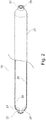
- Fig. 2 shows a concept chart of an Internal Plastic Tank 24 that is composed of Plastic Tank 20 and Connection Port 21.
- Plastic Tank 20 is a cylindrical tank manufactured from plastic and it has two Connection Ports 21 at top and bottom.
- Connection Port 21 is made of stainless steel.
- Connection Port 21 has one penetrating hole, and a plurality of Screw Holes 22 for attachment.
- Plastic Tank 20 and two Connection Ports 21 are built in one body.
- the connection port 21 has a Domed Wing 23 at the bottom of the Connection Port 21. Therefore, Connection Port 21 is prevented from being pushed out from Plastic Tank 20 by internal pressure.
- Fig. 3 shows a concept chart of an Internal Tank 28.
- Internal Tank 28 is composed of a Plastic Tank 25, a Connection Port 26, and Reinforcement FRP Prepreg 27.
- the Plastic Tank 25 is a cylindrical tank manufactured from plastic and it has two Connection Ports 26 at the top and bottom.
- Plastic Tank 25 is reinforced with Reinforcement FRP Prepreg 27.
- Reinforcement FRP Prepreg 27 is made from thermosetting carbon fiber prepreg.
- the Plastic Tank 25 can be easily reinforced, because thermosetting prepreg is a soft and sticky cloth at room temperature.
- Internal Tank 28 is kept in the freezer at minus 5°C or less to prevent deterioration of the thermosetting prepreg.
- Fig. 4A, Fig. 4B, Fig. 4C, Fig. 4D, Fig. 4E and Fig. 4F show the manufacturing process chart of a Pentagon Cell Tank 40.
- Fig. 4A shows a concept chart of an Internal Tank 31.
- Internal Tank 31 is composed of a Reinforced Tank 29 and a Connection Port 30.
- Reinforced Tank 29 is reinforced by thermosetting carbon prepreg.
- Connection Port 30 is a connection port to the adjoining honeycomb cell tank, and it is used for the processing work as well. Two Connection Ports 30 are placed at the top and the bottom of the Reinforced Tank 29.
- Fig. 4B shows a concept chart of an Internal Tank with Height Adapter 33.
- the Internal Tank with Height Adapter 33 is composed of Internal Tank 31 and Height Adaptor 32.
- Height Adaptor 32 is made of steel and used as a bottom support adaptor and a hanging fitting for the Internal Tank 31.
- Height Adaptor 32 is used also for a fitting when Internal Tank 31 is hung down by crane while work process.
- Fig. 4C shows a processing chart of Pentagon Foam Resin.
- Pentagon Foam Resin is manufactured by uniting Quadrangle Foam Resin 34 and Hexagon Foam Resin 35 to surround the Internal Tank 31.
- Quadrangle Foam Resin 34 is in the shape of a foursquare pillar cut in half in the vertical direction. When two Quadrangle Foam Resins 34 are matched together, it becomes a square.
- Hexagon Foam Resin 35 is in the shape of a hexagon pillar cut in half in the vertical direction. When two Hexagon Foam Resins 35 is matched together, it becomes a hexagon.
- Quadrangle Foam Resin 34 and Hexagon Foam Resin 35 are matched together, it becomes a pentagon pillar that has a cylindrical vacant space.
- Cylinder diameter is made 2mm to 5mm bigger than the radius of a Tank Assembly with Height Adapter 33.
- the length of Quadrangle Foam Resin 34 and Hexagon Foam Resin 35 is manufactured as well as Tank Assembly with Height Adapter 33.
- Quadrangle Foam Resin 34 and Hexagon Foam Resin 35 are made from foam resin which begins to foam at about 110°C. The heat foam of Quadrangle Foam Resin 34 and Hexagon Foam Resin 35 continues until they are completely cooled.
- Fig. 4D shows a concept chart of a Pentagon Foam Resin with Internal Tank 36.
- Pentagon Foam Resin with Internal Tank 36 is composed of Tank Assembly with Height Adapter 33, Quadrangle Foam Resin 34 and Hexagon Foam Resin 35.
- Tank Assembly with Height Adapter 33 is placed in the pentagon pillar with cylindrical vacant space. It is also possible to insert Tank Assembly with Height Adapter 33 from the upper side in the inside of the pentagon pillar that has cylindrical vacant space.
- Quadrangle Foam Resin 34 and Hexagon Foam Resin 35 are united with the pressure sensitive adhesive double-coated tape.
- the base material of the double-coated tape a cotton cloth is preferable.
- Fig. 4E shows a processing chart of a Pentagon Cell Tank.
- the Pentagon Cell Tank is manufactured by attaching Quadrangle Prepreg 37 and Hexagon Prepreg 38 to Pentagon Foam Resin with Internal Tank 36.
- Quadrangle Prepreg 37 is a shell made of carbon fiber or glass fiber thermoplastic prepreg, in the shape of a foursquare pillar cut in half in the vertical direction.
- Quadrangle Prepreg 37 is attached to Pentagon Foam Resin with Internal Tank 36 for structural reinforcement.
- Hexagon Prepreg 38 is a shell made of carbon fiber or glass fiber thermoplastic prepreg, whose shape is a cutting into the half of hexagon pillars in the vertical direction.
- Hexagon Prepreg 38 is attached to Pentagon Foam Resin with Internal Tank 36 for structural reinforcement.
- the length of Quadrangle Prepreg 37 and Hexagon Prepreg 38 is manufactured as well as Pentagon Foam Resin with Internal Tank 36.
- the parts manufactured from thermoplastic prepreg soften at about 100°C, and are
- Fig. 4F shows a concept chart of a Pentagon Cell Tank 40.
- Pentagon Cell Tank 40 is composed of Pentagon Foam Resin with Internal Tank 36, Quadrangle Prepreg 37 and Hexagon Prepreg 38.
- Connection Cutting Lack 39 is cut in Pentagon Cell Tank 40.
- Connection Cutting Lacks 39 are placed at the top and the bottom of Pentagon Cell Tank 40.
- Honeycomb structure set tank is composed of the array of plurality of Pentagon Cell Tanks 40, which is a basic component of the honeycomb structure set tank.
- Pentagon Cell Tanks 40 compose the material of the honeycomb structure set tank in the surrounding periphery.
- Quadrangle Prepreg 37 and Hexagon Prepreg 38 are the honeycomb cell walls.
- Connection Cutting Lack 39 is a cutting lack for the connection of the internal tanks built into Pentagon Cell Tank 40.
- Quadrangle Prepreg 37 and Hexagon Prepreg 38 are attached to Pentagon Foam Resin with Internal Tank 36 with pressure sensitive adhesive double-coated tape.
- a cotton cloth is preferable.
- Fig. 5A, Fig. 5B, Fig. 5C, Fig. 5D, Fig. 5E and Fig. 5F shows a manufacturing process chart of a Hexagon Cell Tank.
- Fig. 5A shows a concept chart of an Internal Tank 43.
- Internal Tank 43 is composed of Reinforced Tank 41 and Connection Port 42.
- Reinforced Tank 41 is reinforced by thermosetting carbon prepreg.
- Connection Port 42 is a connection port to the adjoining honeycomb cell tank, and it is used for processing work as well. Two Connection Ports 42 are placed at the top and the bottom of each Reinforced Tank 41.
- Fig. 5B shows a concept chart of an Internal Tank with Height Adapter 45.
- Internal Tank with Height Adapter 45 is composed of Internal Tank 43 and Height Adaptor 44.
- Height Adaptor 44 is made of steel and used as a bottom support adaptor and a hanging fitting of Internal Tank 43.
- Height Adaptor 44 is used as the bottom support of Internal Tank 43. Height Adaptor 44 maintains the height position of Connection Port 43, accurately. Additionally, Height Adaptor 44 is used also for a fitting when Internal Tank 31 is hung down by crane while work process.
- Fig. 5C shows a processing chart of Hexagon Foam Resin.
- Hexagon Foam Resin is manufactured by uniting of two Hexagon Foam Resins 46.
- Hexagon Foam Resin 46 is in the shape of a hexagon pillar cut in half in the vertical direction. When two Hexagon Foam Resins 46 are matched together, they become a hexagon pillar that has cylindrical vacant space. The cylinder diameter is made 2mm to 5mm bigger than radiuses of Tank Assembly with Height Adapter 45.
- Hexagon Foam Resin 46 is manufactured as well as Tank Assembly with Height Adapter 45.
- Hexagon Foam Resin 46 is made from foam resin which begins to foam at about 110°C. The heat foam of Hexagon Foam Resin 46 continues until it is completely cooled.
- Fig. 5D shows a concept chart of a Hexagon Foam Resin with Internal Tank 47.
- Hexagon Foam Resin with Internal Tank 47 is composed of Tank Assembly with Height Adapter 45, and two Hexagon Foam Resins 46.
- Tank Assembly with Height Adapter 45 is placed in the hexagon pillar with cylindrical vacant space. It is also possible to insert Tank Assembly with Height Adapter 45 from the upper side in the inside of the hexagon pillar that has the cylindrical vacant space.
- Two Hexagon Foam Resins 46 are united with the pressure sensitive adhesive double-coated tape.
- the base material of the double-coated tape a cotton cloth is preferable.
- Fig. 5E shows a processing chart of a Hexagon Cell Tank.
- Hexagon Cell Tank is manufactured by attaching two Hexagon Prepregs 48 to Hexagon Foam Resin with Internal Tank 47.
- Hexagon Prepreg 48 is a shell made of carbon fiber or glass fiber thermoplastic prepreg, in the shape of a hexagon pillar cut in half in the vertical direction.
- Hexagon Prepreg 48 is attached to Hexagon Foam Resin with Internal Tank 47 for structural reinforcement.
- the length of Hexagon Prepreg 48 is manufactured as well as Hexagon Foam Resin with Internal Tank 47.
- the parts manufactured from thermoplastic prepreg soften at about 100°C, and are merged at about 130°C.
- Fig. 5F shows a concept chart of a Hexagon Cell Tank 50.
- Hexagon Cell Tank 50 is composed of Hexagon Foam Resin with Internal Tank 47 and two Hexagon Prepregs 48. Connection Cutting Lack 49 is cut in Hexagon Cell Tank 50. Connection Cutting Lacks 49 are placed at the top and the bottom of Hexagon Cell Tank 50.
- the honeycomb structure set tank is composed of an array of a plurality of Hexagon Cell Tanks 50, which is a basic component of the honeycomb structure set tank.
- Hexagon Cell Tank 50 embodies the material of the honeycomb structure set tank in the central part.
- Two Hexagon Prepregs 48 are the honeycomb cell walls.
- Connection Cutting Lack 49 is a cutting lack for the connection of internal tanks built into Hexagon Cell Tank 50.
- Two Hexagon Prepregs 38 are attached to Hexagon Foam Resin with Internal Tank 47 with pressure sensitive adhesive double-coated tape.
- the base material of the double-coated tape a cotton cloth is preferable.
- Fig. 6A shows a processing chart of a Trapezoid Filler.
- Trapezoid Filler is manufactured by attaching Flat Board Prepreg 52 and Trapezoid Prepreg 53 to Trapezoid Foam Resin 51.
- Trapezoid Foam Resin 51 is made from foam resin which begins to foam at about 110°C and Trapezoid Foam Resin 51 continues foaming until being completely cooled.
- Flat Board Prepreg 52 and Trapezoid Prepreg 53 are made from carbon or glass fiber thermoplastic prepreg. The shape of Flat Board Prepreg 52 is equal to a trapezoid bottom of Trapezoid Foam Resin 51.
- Trapezoid Prepreg 53 is a shell made of carbon fiber or glass fiber thermoplastic prepreg whose shape is equal to a trapezoid upper shape of Trapezoid Foam Resin 51.
- Flat Board Prepreg 52 and Trapezoid Prepreg 53 are attached to Trapezoid Foam Resin 51 with the pressure sensitive adhesive double-coated tape.
- the base material of the double-coated tape a cotton cloth is preferable.
- Fig. 6B shows a concept chart of a Trapezoid Filler 54.
- Trapezoid Filler 54 is composed of Trapezoid Foam Resin 51, Flat Board Prepreg 52 and Trapezoid Prepreg 53.
- Trapezoid Filler 54 is a part to correct irregularities or voids, which are created at the surrounding portions of the honeycomb structure.
- the lengths of Trapezoid Foam Resin 51, Flat Board Prepreg 52 and Trapezoid Prepreg 53 are equal to the length of the honeycomb structure to be manufactured.
- Fig. 7 shows an image chart of a Honeycomb Set Tank 59.
- the external shape of Honeycomb Set Tank 59 is a hexahedron.
- Honeycomb Set Tank 59 is composed of pluralities of Pentagon Cell Tanks 56, Hexagon Cell Tanks 57 and Trapezoid Fillers 58.
- Internal Tanks 55 are stored in Pentagon Cell Tanks 56 and Hexagon Cell Tanks 57.
- Pentagon Cell Tanks 56 are placed surrounding the Honeycomb Set Tanks 59.
- Hexagon Cell Tanks 57 are positioned centrally relative to the Honeycomb Set Tanks 59.
- Trapezoid Filler Assemblies 58 are used to correct the irregularities and voids, which is formed along the surrounding portions of the honeycomb structure.
- Internal Tank 55 is heated and pressurized by the compressed air at high temperature from the inside.
- the entire Honeycomb Set Tank 59 is heated from outside in a large-scale heat oven.
- the heat foam resin included in Pentagon Cell Tanks 56, Hexagon Cell Tanks 57 and Trapezoid Fillers 58 foams and expands when heated to a high temperature.
- thermoplastic carbon fiber or glass fiber prepreg shells are attached on the surfaces of Pentagon Cell Tanks 56, Hexagon Cell Tanks 57 and Trapezoid Fillers 58.
- the thermoplastic carbon fiber or glass fiber prepreg shells are divided into two parts. So, the thermoplastic carbon fiber or glass fiber prepreg shells, which are structural material of the honeycomb structure, can freely expand.
- the thermoplastic carbon fiber or glass fiber prepreg shell melts when Honeycomb Set Tank 59 is heated to about 130°C. Then, pluralities of Pentagon Cell Tank 56, Hexagon Cell Tank 57 and Trapezoid Filler 58 are merged mutually.
- Internal Tanks 55 that are stored in Pentagon Cell Tanks 56 and Hexagon Cell Tanks 57 are strongly pressurized by the heat foam resin.
- the surface of Internal Tank 55 is reinforced by accumulated carbon fiber thermosetting prepregs.
- carbon fiber prepregs are strongly pressurized with the heat foam resin and internal pressure of Internal Tank 55. Then, the accumulated carbon fiber thermosetting prepregs of Internal Tank 55 are merged mutually.
- Fig. 8A and Fig. 8B shows a concept chart of a Container Wall Assembly 66.
- the manufacturing process for a Honeycomb Set Tank will be explained with an example of a ten-foot container.
- FIG. 8A shows a plan chart of a Container Wall Assembly 66.
- Fig. 8B shows a front chart of a Container Wall Assembly 66.
- Container Wall Assembly 66 is composed of Bottom Wall 60, Top Wall 61, Rear Wall 62, Front Wall 63, Left Side Wall 64 and Right Side Wall 65.
- Bottom Wall 60, Top Wall 61, Rear Wall 62, Front Wall 63, Left Side Wall 64 and Right Side Wall 65 are manufactured from steel and they are boards with a flat inside wall, and the outside wall is a corrugated plate.
- Fig. 9A and Fig. 9B show processing charts of a Container Honeycomb Cell.
- Fig. 9A shows a plan chart and Fig. 9B shows a front chart.
- the Container Honeycomb Cell is composed of Bottom Wall 67, Rear Wall 68, Left Side Wall 69, Rear Cushion Wall 70, Left Side Cushion Wall 71, Pentagon Honeycomb Cell 72, Hexagon Honeycomb Cell 73 and Trapezoid Filler 74.
- Bottom Wall 67, Rear Wall 68 and Left Side Wall 69 are manufactured from steel and they are boards with a flat inside wall, and the outside wall is a corrugated plate.
- Rear Cushion Wall 70 and Left Side Cushion Wall 71 are manufactured from heat foam resin and they protect the honeycomb set tank from external shock loading.
- Pentagon Honeycomb Cell 72 is composed of a pentagon heat form resin and a pentagon shell made of carbon fiber or glass fiber thermoplastic prepreg.
- Hexagon Honeycomb Cell 73 is composed of a hexagon heat form resin and a hexagon shell made of carbon fiber or glass fiber thermoplastic prepreg.
- Trapezoid Filler 74 is composed of a trapezoid hexagon heat form resin and a trapezoid shell made of carbon fiber or glass fiber thermoplastic prepreg.
- the Manufacturing process for the Container Honeycomb Cell is composed of three steps:
- Pentagon Honeycomb Cells 72 are placed surrounding the outer portions of the Container Honeycomb Cell. Hexagon Honeycomb Cells 73 are placed at the central part. Trapezoid Fillers 74 are filled in to correct the irregularities and voids which result along the outer surrounding periphery of the honeycomb structure.
- the outer shells of Pentagon Honeycomb Cells 72, Hexagon Honeycomb Cells 73 and Trapezoid Fillers 74 are manufactured from thermoplastic carbon fiber or glass fiber prepreg. Thermoplastic carbon fiber or glass fiber prepreg is not cohesive at the room temperature, so the assembly operation of the honeycomb structure is not difficult.
- Fig. 10A and Fig. 10B show a concept chart of a Container Honeycomb Cell 87.
- Fig. 10A shows a plan concept chart of Container Honeycomb Cell 87.
- Fig. 10B shows a front concept chart.
- Container Honeycomb Cells 87 are composed of Bottom Wall 75, Rear Wall 76, Front Wall 77, Left Side Wall 78, Right Side Wall 79, Rear Cushion Wall 80, Front Cushion Wall 81, Left Side Cushion Wall 82, Right Side Cushion Wall 83, Pentagon Honeycomb Cells 84, Hexagon Honeycomb Cells 85 and Trapezoid Fillers 86.
- Bottom Wall 75, Rear Wall 76, Front Wall 77, Left Side Wall 78 and Right Side Wall 79 are manufactured from steel.
- Rear Cushion Wall 80, Front Cushion Wall 81, Left Side Cushion Wall 82 and Right Side Cushion Wall 83 are manufactured from heat foam resin.
- Pentagon Honeycomb Cells 84, Hexagon Honeycomb Cells 85 and Trapezoid Fillers 86 are manufactured from heat foam resin and carbon fiber or glass fiber thermoplastic prepreg.
- Pentagon Honeycomb Cells 84, Hexagon Honeycomb Cells 85 and Trapezoid Fillers 86 are manufactured from heat foam resin and carbon fiber or glass fiber thermoplastic prepreg.
- Each Pentagon Honeycomb Cell 84 and Hexagon Honeycomb Cell 85 has a large cavity, wherein an internal tank is stored in each cavity.
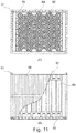
- Fig. 11A and Fig. 11B show a processing chart of a Container Honeycomb Cell Tank with Height Adapter 91.
- Fig. 11A shows a plan chart
- Fig. 11B shows a front chart.
- Container Honeycomb Cell Tank with Height Adapter 91 is composed of Container Honeycomb Cell 88, Internal Tank 89 and Height Adapter 90.
- Container Honeycomb Cell 88 is the same as Container Honeycomb Cell 87 in Fig. 10 .
- Internal Tank 89 is the same as Internal Tank 31 in Fig. 4 and Internal Tank 43 in Fig. 5 .
- Height Adapter 90 is the same as Height Adapter 32 in Fig. 4 and Height Adapter 44 in Fig. 5 .
- Container Honeycomb Cell Tank with Height Adapter 91 is assembled by inserting Internal Tank 89, to which Height Adapter 90 is attached, into the cavity of Container Honeycomb Cell 88. Internal Tank 89 is inserted into Container Honeycomb Cell 88 from above by crane. The assembling operation of a Container Honeycomb Cell Tank with Height Adapter 91 is not difficult, because the cavity diameter of each Container Honeycomb Cell 88 is larger than the diameter of Internal Tank 89.
- Fig. 12A and Fig. 12B show a processing chart of a Container Honeycomb Cell Tank Top Piping 98.
- Fig. 12A shows a plan chart.
- Fig. 12B shows a front chart.
- Container Honeycomb Cell Tank Top Piping 98 is composed of Internal Tanks 92, Pentagon Honeycomb Cells 93, Hexagon Honeycomb Cells 94, Height Adapters 95, Shut Off Valves 96 and Top Pipings 97.
- Pentagon Honeycomb Cells 93 are the same as Pentagon Cell Tanks 40.
- Hexagon Honeycomb Cells 94 is the same as Hexagon Cell Tank 50.
- Internal Tank 92 and Height Adapter 95 is the same as Internal Tank 31, Height Adapter 32 in Fig. 4 and Internal Tank 43, Height Adapter 44 in Fig. 5 .
- Container Honeycomb Cell Tank Top Piping 98 is assembled by attaching Shut Off Valve 96 and connecting Top Piping 97 to Internal Tank 92. Height Adapter 95 at the top of Internal Tank 92 is removed before attaching Shut Off Valve 96 and Top Piping 97.
- Top Piping 97 It is easy to connect Top Piping 97 to Internal Tank 92, because Top Piping 97 only ties two Internal Tanks 92. Internal Tank 92 can be rotated freely in the cylindrical cavity of Pentagon Honeycomb Cell 93 and Hexagon Honeycomb Cell 94. Additionally, Height Adapter 95 at the bottom uniformly adjusts the height position of the connection ports. Shut Off Valve 96 is attached to Internal Tank 92. Therefore, Top Piping 97 actually connects two Shut Off Valves 96. After the Top Piping is finished, the vacant space above Internal Tank 92 is filled with the granulated powder foam resin, and Top Wall of container is installed. The Top Wall of the container is not shown in Fig. 12 .
- Fig. 13A show a plan chart of a Honeycomb Container Tank with Piping 114.
- Fig. 13B show a front chart of a Honeycomb Container Tank with Piping 114.
- Fig. 13A and Fig. 13B show a concept chart of a Honeycomb Container Tank with Piping 114.
- Honeycomb Container Tank With Piping 114 is composed of Internal Tanks 99, Pentagon Honeycomb Cells 100, Hexagon Honeycomb Cells 101, Cushion Wall 102, Bottom Wall 103, Top Wall 104, Rear Wall 105, Front Wall 106, Left Side Wall 107, Right Side Wall 108, Shut Off Valves 109, Top Piping 110, Bottom Piping 111, Entrance Connection 112 and Exit Connection 113.
- Internal Tanks 99 are the same as Internal Tanks 92 in Fig. 12 .
- Pentagon Honeycomb Cells 100 are the same as Pentagon Cell Tanks 84 in Fig. 10 .
- Hexagon Honeycomb Cells 101 are the same as Hexagon Cell Tanks 85 in Fig. 10 .
- Cushion Wall 102 is made of heat foam resin and becomes the cushioning material of the honeycomb set tank.
- Bottom Wall 103, Top Wall 104, Rear Wall 105, Front Wall 106, Left Side Wall 107, Right Side Wall 108 are the same as Bottom Wall 60, Top Wall 61, Rear Wall 62, Front Wall 63, Left Side Wall 64, Right Side Wall 65 in Fig. 8 .
- Shut Off Valve 109 and Top Piping 110 is the same as Shut Off Valve 96 and Top Piping 97 in Fig. 12 .
- Bottom Piping 111 is the piping at the bottom of Internal Tanks 99.
- the piping of the bottom is processed with the honeycomb container tank turned 180 degrees and in reverse. All Internal Tanks 99 are connected in series. It is a little difficult to attach Shut Off Valve 109 and to connect Bottom Piping 111 to Internal Tank 99.
- Internal Tank 99 cannot be rotated freely in the cylindrical cavity of Pentagon Honeycomb Cell 100 and Hexagon Honeycomb Cell 101, because the top of Internal Tank 99 is already fixed by Top Piping 110. It is necessary to note it is because the piping of Bottom Piping 111 makes a mistake easily in the connection order. The leakage inspection of piping is necessary. After the piping work has finished, the vacant space above Internal Tank 99 is filled with the granulated powder foam resin, and the container wall is installed.
- Fig. 14A shows a plan chart of a Reinforcement Frame Device 121.
- Fig. 14B shows a front chart.
- Fig. 14A and Fig. 14B shows a concept chart of a Reinforcement Frame Device 121.
- Reinforcement Frame Device 121 is composed of Bottom Frame 115, Top Frame 116, Rear Frame 117, Front Frame 118, Left Side Frame 119 and Right Side Frame 120. These frames are manufactured from steel.
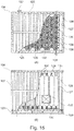
- Fig. 15A shows a plan chart of a High-Pressure Container Tank 134.
- Fig. 15B shows a front chart of a High-Pressure Container Tank 134.
- Fig. 15A and Fig. 15B show a concept chart of a High-Pressure Container Tank 134.
- High-Pressure Container Tank 134 is composed of Container Wall 122, Container Base Palette 123, Pentagon Honeycomb Cells 124, Hexagon Honeycomb Cells 125, Trapezoid Fillers 126, Cushion Wall 127, Internal Tank 128, Shut Off Valves 129, Internal Tank Piping 130, Entrance Connection 131, Exit Connection 132 and Control Board 133.
- High-Pressure Container Tank 134 is an example of honeycomb structural high-pressure set tank, and is designed so that it is accommodated in an ISO ten-foot container.
- Container Wall 122 is the most outside protection wall of Internal Tank 128 and is hexahedron made of steel.
- Container Base Palette 123 is welded under High-Pressure Container Tank 134, and transports High-Pressure Container Tank 134 conveniently.
- Cushion Wall 127 is manufactured from the heat foam resin and is the second protection of Internal Tanks 128.
- Pentagon Honeycomb Cells 124, Hexagon Honeycomb Cells 125 and Trapezoid Fillers 126 are manufactured from the heat foam resin. The heat foam resin foams and expands when heated.
- the outer shells of Pentagon Honeycomb Cells 124, Hexagon Honeycomb Cells 125 and Trapezoid Fillers 126 are made of thermoplastic carbon fiber prepreg or thermoplastic glass fiber prepreg. These outer shells mutually merge by the heat-treatment process, and then the shape of merged shells becomes a honeycomb structure.
- the strong honeycomb cell manufactured from carbon fiber or the glass fiber is the third protection of Internal Tanks 128.
- the honeycomb structure built with carbon fiber or the glass fiber protects Internal Tanks 128 from external shock loading.
- the heat form resin, which is formed by a heat-treatment process, is the fourth protection of Internal Tanks 128.
- Internal Tank 128 is made from plastic and is reinforced by thermosetting carbon fiber prepreg. The reinforcement structure of Internal Tank 128 is designed to endure the high pressure in a single tank alone. All Internal Tanks 128 are enclosed in High-Pressure Container Tank 134. They are connected in series, by Internal Tank Piping 130. Two Shut Off Valves 129 are attached at the top and bottom of each Internal Tank 128. Shut Off Valve 129 is used when High-Pressure Container Tank 134 is manufactured. They need heat proofing, because the Shut Off Valves 129 are heated at heat treatment process. Shut Off Valves 129 are permanently enclosed in High-Pressure Container Tank 134. Shut Off Valve 129 is also used when High-Pressure Container Tank 134 is transported.
- Control Board 133 controls the opening and shutting of Shut Off Valve 129.
- Shut Off Valve 129 can minimize a potential disaster due to Internal Tank 128 being damaged accidentally while transporting High-Pressure Container Tank 134.
- Entrance Connection 131 and Exit Connection 132 are the connecting ports to the outside.
- This invention is the one invented to improve US Patent No. 8,917,809 B2 .
- Manufacturing the large-scale container set tank is difficult by US Patent No. 8,917,809 B2 , because the patent heats the honeycomb cell from the outside.
- the method of the new invention can be applied to the pillar of a large-scale honeycomb structure.
- it is difficult to make a honeycomb cell with high size accuracy by the patent of US 8,917,809 B2 because the patent manufactures the honeycomb cell with thermosetting prepreg.
- the method of the new invention can be applied to the rapid-transit railway and the aircraft.
Landscapes
- Engineering & Computer Science (AREA)
- Mechanical Engineering (AREA)
- General Engineering & Computer Science (AREA)
- Moulding By Coating Moulds (AREA)
- Laminated Bodies (AREA)
Applications Claiming Priority (1)
| Application Number | Priority Date | Filing Date | Title |
|---|---|---|---|
| US15/070,354 US10364942B2 (en) | 2016-03-15 | 2016-03-15 | Honeycomb structural high-pressure set tank and a manufacturing process therefor |
Publications (2)
| Publication Number | Publication Date |
|---|---|
| EP3236131A2 true EP3236131A2 (fr) | 2017-10-25 |
| EP3236131A3 EP3236131A3 (fr) | 2017-11-08 |
Family
ID=58387647
Family Applications (1)
| Application Number | Title | Priority Date | Filing Date |
|---|---|---|---|
| EP17161137.9A Withdrawn EP3236131A3 (fr) | 2016-03-15 | 2017-03-15 | Ensemble réservoir haute pression à structure en nid d'abeille et son procédé de fabrication |
Country Status (2)
| Country | Link |
|---|---|
| US (1) | US10364942B2 (fr) |
| EP (1) | EP3236131A3 (fr) |
Families Citing this family (3)
| Publication number | Priority date | Publication date | Assignee | Title |
|---|---|---|---|---|
| GB2572559B (en) * | 2018-04-03 | 2020-12-09 | Sarchex Ltd | Hexagonal pressure vessel formed of folded sheets |
| FR3088358B1 (fr) * | 2018-11-12 | 2022-01-14 | Ifp Energies Now | Reservoir pour le stockage d'un fluide sous pression et procede de fabrication du reservoir |
| CN115609946B (zh) * | 2022-09-15 | 2025-09-12 | 南京玻璃纤维研究设计院有限公司 | 一种滑动式蜂窝预制体定型模具及方法 |
Citations (1)
| Publication number | Priority date | Publication date | Assignee | Title |
|---|---|---|---|---|
| US8917809B2 (en) | 2012-02-28 | 2014-12-23 | Tsukasa NOZAWA | Honeycomb structure having honeycomb core arranged parallel to a panel surface and a manufacturing process therefor |
Family Cites Families (14)
| Publication number | Priority date | Publication date | Assignee | Title |
|---|---|---|---|---|
| US2537085A (en) * | 1946-10-25 | 1951-01-09 | Warren Petroleum Corp | Cargo-type tank vessel having separable tanks |
| US3537416A (en) | 1969-01-02 | 1970-11-03 | Exxon Research Engineering Co | Shipping container and method for transporting hydrocarbon fluids and the like |
| US3641230A (en) | 1969-01-21 | 1972-02-08 | Dura Fiber | Method for making prestressed laminated fiber glass structures |
| US4063999A (en) | 1976-01-28 | 1977-12-20 | Westinghouse Electric Corporation | Nuclear fuel storage arrangement |
| GB2058720B (en) | 1979-09-20 | 1983-05-05 | Wes Ltd | Storage and transport containers for ammunition |
| US5174466A (en) * | 1991-04-25 | 1992-12-29 | Culligan International Company | Tank lining system with neck seal |
| US6655633B1 (en) | 2000-01-21 | 2003-12-02 | W. Cullen Chapman, Jr. | Tubular members integrated to form a structure |
| JP4862975B2 (ja) | 2000-02-03 | 2012-01-25 | 司 野澤 | ハニカム構造体、ハニカムセルおよびハニカム構造体の製造方法 |
| DE60013915T2 (de) * | 2000-04-26 | 2005-09-29 | Altech Co., Ltd. | Stossdämpfendes verpackungsmaterial und verfahren und vorrichtung zum herstellen desselben |
| JP4705251B2 (ja) | 2001-01-26 | 2011-06-22 | 本田技研工業株式会社 | Mhタンク |
| US20040145079A1 (en) | 2003-01-27 | 2004-07-29 | Yung-Kun Lin | Composite material member having reinforcement ribs and method for making the same |
| FR2896613B1 (fr) | 2006-01-26 | 2010-10-15 | Commissariat Energie Atomique | Element de stockage de combustible nucleaire empilable et module de stockage forme par un empilement de tels elements |
| US8011312B2 (en) * | 2008-08-29 | 2011-09-06 | Horton Wison Deepwater, Inc. | Floating oil storage system and method |
| WO2010057089A1 (fr) | 2008-11-17 | 2010-05-20 | Textron Systems Corporation | Techniques de formation de revêtements protecteurs temporaires et de surfaces aptes à être collées |
-
2016
- 2016-03-15 US US15/070,354 patent/US10364942B2/en active Active
-
2017
- 2017-03-15 EP EP17161137.9A patent/EP3236131A3/fr not_active Withdrawn
Patent Citations (1)
| Publication number | Priority date | Publication date | Assignee | Title |
|---|---|---|---|---|
| US8917809B2 (en) | 2012-02-28 | 2014-12-23 | Tsukasa NOZAWA | Honeycomb structure having honeycomb core arranged parallel to a panel surface and a manufacturing process therefor |
Also Published As
| Publication number | Publication date |
|---|---|
| US20170268728A1 (en) | 2017-09-21 |
| US10364942B2 (en) | 2019-07-30 |
| EP3236131A3 (fr) | 2017-11-08 |
Similar Documents
| Publication | Publication Date | Title |
|---|---|---|
| US10364942B2 (en) | Honeycomb structural high-pressure set tank and a manufacturing process therefor | |
| EP0505927A2 (fr) | Barillet de missiles et méthode de fabrication | |
| CA1264908A (fr) | Corps creux arme de fibres, et sa fabrication | |
| CN108061241B (zh) | 一种可重复使用复合材料气瓶及其设计方法 | |
| CN104220247B (zh) | 具有与板表面平行设置的蜂窝芯的蜂窝结构以及蜂窝结构的制造方法 | |
| US10954915B2 (en) | Wind turbine blade manufacture | |
| EP3268199B1 (fr) | Procédé et mandrin pour la fabrication d'objets enveloppés | |
| US8899835B2 (en) | Self-supporting bladder system for a double wall tank | |
| US20100230417A1 (en) | Vessel for a compressed gas and method for producing the vessel | |
| US20190224074A1 (en) | Housing for a flexible container | |
| US20080087665A1 (en) | Freight container | |
| US9555959B1 (en) | Modular fluid storage tank | |
| US10208280B2 (en) | System and method of preservation, storage and transport of biological materials | |
| CN1331816C (zh) | 用于加固天然石材块的方法 | |
| US7503758B2 (en) | Syntactic tunnel core | |
| US10464743B2 (en) | Tank made of a composite material | |
| CN107144471A (zh) | 一种用于模型试验的承压溶洞水压加载密封装置及方法 | |
| US10160595B1 (en) | Modular fluid storage tank | |
| EP0025792A1 (fr) | Receptacle formant reservoir isole. | |
| RU2215216C2 (ru) | Сосуд давления и способ его изготовления | |
| CN210690040U (zh) | 一种双气源低温安全阀校验台 | |
| US11639040B2 (en) | Shape memory manufacturing for vessels | |
| CN224064364U (zh) | 一种用于跨断层隧道泡沫混凝土缓冲层施工的气囊装置 | |
| ES3008057T3 (en) | Composite manufacturing method | |
| CN213567551U (zh) | 一种蜂窝型缓冲气柱 |
Legal Events
| Date | Code | Title | Description |
|---|---|---|---|
| PUAI | Public reference made under article 153(3) epc to a published international application that has entered the european phase |
Free format text: ORIGINAL CODE: 0009012 |
|
| STAA | Information on the status of an ep patent application or granted ep patent |
Free format text: STATUS: THE APPLICATION HAS BEEN PUBLISHED |
|
| PUAL | Search report despatched |
Free format text: ORIGINAL CODE: 0009013 |
|
| AK | Designated contracting states |
Kind code of ref document: A2 Designated state(s): AL AT BE BG CH CY CZ DE DK EE ES FI FR GB GR HR HU IE IS IT LI LT LU LV MC MK MT NL NO PL PT RO RS SE SI SK SM TR |
|
| AX | Request for extension of the european patent |
Extension state: BA ME |
|
| AK | Designated contracting states |
Kind code of ref document: A3 Designated state(s): AL AT BE BG CH CY CZ DE DK EE ES FI FR GB GR HR HU IE IS IT LI LT LU LV MC MK MT NL NO PL PT RO RS SE SI SK SM TR |
|
| AX | Request for extension of the european patent |
Extension state: BA ME |
|
| RIC1 | Information provided on ipc code assigned before grant |
Ipc: F17C 13/00 20060101ALI20171004BHEP Ipc: F17C 1/16 20060101ALI20171004BHEP Ipc: F17C 13/08 20060101ALI20171004BHEP Ipc: F17C 1/00 20060101AFI20171004BHEP Ipc: B65D 90/20 20060101ALI20171004BHEP |
|
| STAA | Information on the status of an ep patent application or granted ep patent |
Free format text: STATUS: THE APPLICATION IS DEEMED TO BE WITHDRAWN |
|
| 18D | Application deemed to be withdrawn |
Effective date: 20180509 |