EP3236143A1 - Gelenkstruktur - Google Patents
Gelenkstruktur Download PDFInfo
- Publication number
- EP3236143A1 EP3236143A1 EP17165928.7A EP17165928A EP3236143A1 EP 3236143 A1 EP3236143 A1 EP 3236143A1 EP 17165928 A EP17165928 A EP 17165928A EP 3236143 A1 EP3236143 A1 EP 3236143A1
- Authority
- EP
- European Patent Office
- Prior art keywords
- articulated structure
- elements
- rotation
- friction
- structure according
- Prior art date
- Legal status (The legal status is an assumption and is not a legal conclusion. Google has not performed a legal analysis and makes no representation as to the accuracy of the status listed.)
- Granted
Links
Images


Classifications
-
- F—MECHANICAL ENGINEERING; LIGHTING; HEATING; WEAPONS; BLASTING
- F21—LIGHTING
- F21V—FUNCTIONAL FEATURES OR DETAILS OF LIGHTING DEVICES OR SYSTEMS THEREOF; STRUCTURAL COMBINATIONS OF LIGHTING DEVICES WITH OTHER ARTICLES, NOT OTHERWISE PROVIDED FOR
- F21V21/00—Supporting, suspending, or attaching arrangements for lighting devices; Hand grips
- F21V21/14—Adjustable mountings
- F21V21/26—Pivoted arms
Definitions
- This invention relates to an articulated structure.
- this invention relates to an articulated structure equipped with a friction member.
- this invention relates to an articulated structure equipped with a friction member and integrated in lighting structures, such as spotlights and lighting projectors.
- the spotlights are usually inserted in rectilinear guides which simplify both the positioning that the powering. Once positioned, the spotlights must then be oriented to direct the light beam in the desired direction.
- the spotlights are usually connected to the guide by supports, such as arms or articulated arms.
- the supports although they provide a certain versatility in the orientation of the spotlights, are not free from drawbacks.
- a first drawback consists in the fact that many of these supports have friction connections and joints for friction which must therefore be loosened before the adjustment and subsequently tightened once the desired configuration has been identified.
- a further drawback connected to the use of the supports of known type is due to the fact that sometimes the spotlight is not easily accessible, thereby making the above-mentioned loosening and tightening operations even more difficult..
- the aim of this invention is to provide an articulated model which is able to overcome the drawbacks of the prior art and which is at the same time practical to use and simple to make.
- a further aim of this invention is to provide an articulated structure which is easy to adjust and which is stable in its configuration.
- a further aim of this invention is to provide an articulated structure which is inexpensive to make.
- Another aim of the invention is to provide a method for assembling an articulated structure which is simple and practical to implement.
- the numeral 1 denotes in its entirety an articulated structure made in accordance with this invention.
- the articulated structure 1 according to the invention is advantageously used to support lighting devices, not illustrated, such as spotlights and the like.
- the articulated structure 1 comprises a first element 2 with an elongate shape and a second element 3 also with an elongate shape.
- the first and second elements 2, 3 are advantageously made of sheet metal.
- the elements 2, 3 are made by casting, in configurations which are also not flat.
- first and second elements 2, 3 are equal and interchangeable.
- the elements 2, 3 have different lengths.
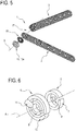
- first element 2 and second element 3 are pivoted to each other by a pin 4, shown in Figure 4 .
- the pivot pin 4 makes the first and second elements 2, 3 movable relative to each other in a tilting fashion about a predetermined axis of rotation A, coinciding with a central axis of the pin 4.
- the two first and second elements 2, 3 have respective circular through holes 20, 30 designed to allow the insertion of the pin 4.
- the articulated structure 1 comprises, operatively positioned between the two first and second elements 2, 3, a first friction member 5 with a circular extension and a second friction member 6 with a circular extension.
- the first friction member 5 comprises an annular C-shaped wall 7.
- the annular wall 7 has the form of a cylindrical ring without an axial extension portion.
- the first friction member 5 also comprises a tab 8 protruding in an axial direction from the annular wall 7 and integral with the latter.
- the tab 8 as clearly shown in Figures 2 and 3 , is configured to be inserted in the respective cavity 21 which is exactly shaped to match, for making the first friction member 5 integral with the first element 2 relative to the rotation of the latter about the axis A.
- the second friction member 6 comprises two concentric annular walls 9, 10, respectively smaller and larger, both C-shaped.
- the two smaller and larger annular walls 9, 10 both have the shape of a cylindrical ring without a portion with axial extension.
- the second friction member 6 also comprises a tab 11 protruding in an axial direction from the annular walls 9, 10 and integral with them.
- the tab 11 rigidly connects the two smaller and larger annular walls 9, 10, guaranteeing also their concentricity.
- the tab 11 is configured to be inserted in the respective cavity 31 which is exactly shaped to match, for making the section friction member 6 integral with the second element 3 relative to the rotation of the latter about the axis A.
- first and second friction members 5, 6 interpenetrate with each other in the direction of the predetermined axis of rotation A.
- annular wall 7 of the first friction member 5 is inserted between the two smaller and larger annular concentric walls 9, 10 of the second member 6, in a concentric fashion.
- cylindrical surfaces is used to mean the approximately cylindrical inner and outer faces (apart from, that is, the missing portion) of the annular walls 7, 9, 10 of the friction members 5, 6.
- the rivet 12 is of the expansion type and comprises a male element 13 and a female element 14, both these male and female elements 13, 14 having respective heads 13a, 14a.
- the rivet 12 defines, with its elements 13, 14, the above-mentioned pivot pin 4.
- the two first and second friction members 5, 6 interpenetrate with each other in such a way that their axial dimension reduces to that of only one of the two, after which the respective tabs 8, 11 are inserted in respective cavities 21, 31 of the first and second elements 2, 3, located with the holes 20, 30 coaxial with each other and the annular walls 7, 9, 10.
- Two Belleville springs 15, 16 are positioned outside the first and second elements 2, 3, coaxial with the holes 20, 30.
- the Belleville springs 15, 16 usefully perform the purpose of eliminating any possible axial clearances in the assembly of the articulated structure 1.
- the above-mentioned Belleville springs 15, 16 are interposed between a respective head 13a, 14a of the rivet 12 and the outer surfaces of the first and second elements 2 and 3.
- the female element 14 is positioned with a relative outer cylindrical surface facing an inner cylindrical surface of the smaller annular wall 9 of the second friction member 6.
- the tightening in a pack by the rivet 12 is advantageously actuated by a compression of the two elements 13, 14 in the direction of the axis of rotation A, as indicated by the arrows F in Figure 2 ; this compression is achieved with a suitable press not illustrated.
- This compression on the basis of the operating principle of the rivet 12, determines a radial expansion of the rivet 12, the expansion of which is transmitted to the adjacent smaller annular wall 9.
- the smaller annular wall 9 acts like a spring, deforming elastically when opening and transmitting in turn the deformation to the adjacent annular wall 7 of the first friction member 5.
- annular wall 7 of the first friction member 5 deforms elastically and transmits the relative deformation to the larger annular wall 10 which in turn will undergo any elastic deformation.
- the described succession of deformations therefore brings the surfaces in contact with the annular walls 7, 9, 10 to generate a mutual rubbing together, at a rotation of the elements 2, 3, which generates respective friction forces resulting from the above-mentioned rotation.
- first and second friction members 5, 6 thus define, for the articulated structure 1, respective friction means 17 which are operatively positioned between the first and second elements 2, 3 to obstruct the reciprocal rotation.
- the above-mentioned rivet 12, with its male and female elements 13, 14 and Belleville springs 15, 16 define, in their entirety for the articulated structure 1, respective means 18 for clamping in a pack, in the direction of the predetermined axis of rotation A, the first and second elements 2, 3 and the first and second friction members 5, 6 interposed between them.
- the invention also relates to a method for assembling an articulated structure and comprises a plurality of steps.
- a first step consists in preparing a first element 2 and a second element 3 with an elongate shape which are pivoted to each other by means of a pin 4, to make the first and the second elements 2, 3 movable relative to each other in tilting fashion around a predetermined axis of rotation A.
- a subsequent step comprises preparing a first friction member 5 with a circular extension, which is integral in rotation with one of the above-mentioned first and second elements 2, 3, and a second friction member 6 with a circular extension, which is integral in rotation with the other of the above-mentioned first and second elements 2, 3, with the first and second friction members 5, 6 interpenetrating with each other in the direction of the predetermined axis of rotation A.
- the method according to the invention therefore requires positioning an expansion rivet 12, passing centrally inside the first and second friction members 5, 6, and pressing the expansion rivet 12 to close the articulated structure 1 tightly in a pack and to radially force the friction members 5, 6 so as to increase the friction force generated on respective surfaces in mutual contact.
- the friction members 5, 6 are made by casting, and are preferably made of zama.
- This invention achieves the preset aims and brings important advantages.
- the articulated structure 1 according to the invention is exceptionally compact at the pivot and the friction members have a limited size.
- the articulated structure 1 does not require any adjustment in use of the friction force which is determined in advance also as a function of the diameter of the rivet which can also vary as a function of the load which the articulated structure 1 is designed to support.
Landscapes
- Engineering & Computer Science (AREA)
- General Engineering & Computer Science (AREA)
- Pivots And Pivotal Connections (AREA)
Applications Claiming Priority (1)
| Application Number | Priority Date | Filing Date | Title |
|---|---|---|---|
| ITUA2016A002755A ITUA20162755A1 (it) | 2016-04-20 | 2016-04-20 | Struttura articolata |
Publications (2)
| Publication Number | Publication Date |
|---|---|
| EP3236143A1 true EP3236143A1 (de) | 2017-10-25 |
| EP3236143B1 EP3236143B1 (de) | 2019-03-13 |
Family
ID=56740315
Family Applications (1)
| Application Number | Title | Priority Date | Filing Date |
|---|---|---|---|
| EP17165928.7A Not-in-force EP3236143B1 (de) | 2016-04-20 | 2017-04-11 | Gelenkstruktur |
Country Status (2)
| Country | Link |
|---|---|
| EP (1) | EP3236143B1 (de) |
| IT (1) | ITUA20162755A1 (de) |
Citations (3)
| Publication number | Priority date | Publication date | Assignee | Title |
|---|---|---|---|---|
| DE334417C (de) * | 1919-09-02 | 1921-03-17 | Helmholz & Pauli | Reibungsgelenk fuer Kipplampen |
| DE1090759B (de) * | 1958-01-25 | 1960-10-13 | Egon Hillebrand | Gelenkleuchte |
| US20060096444A1 (en) * | 2004-11-08 | 2006-05-11 | Hoshino Gakki Mfg. Co., Ltd. | Angle adjustor |
-
2016
- 2016-04-20 IT ITUA2016A002755A patent/ITUA20162755A1/it unknown
-
2017
- 2017-04-11 EP EP17165928.7A patent/EP3236143B1/de not_active Not-in-force
Patent Citations (3)
| Publication number | Priority date | Publication date | Assignee | Title |
|---|---|---|---|---|
| DE334417C (de) * | 1919-09-02 | 1921-03-17 | Helmholz & Pauli | Reibungsgelenk fuer Kipplampen |
| DE1090759B (de) * | 1958-01-25 | 1960-10-13 | Egon Hillebrand | Gelenkleuchte |
| US20060096444A1 (en) * | 2004-11-08 | 2006-05-11 | Hoshino Gakki Mfg. Co., Ltd. | Angle adjustor |
Also Published As
| Publication number | Publication date |
|---|---|
| EP3236143B1 (de) | 2019-03-13 |
| ITUA20162755A1 (it) | 2017-10-20 |
Similar Documents
| Publication | Publication Date | Title |
|---|---|---|
| KR101680547B1 (ko) | 스프링클러 헤드 | |
| JP5951124B2 (ja) | 押圧ジョー、分離不能管継手の製作方法、結合具、および押圧ジョーと結合具とから成るシステム | |
| RU2683192C1 (ru) | Соединительное устройство для компонентов предмета мебели | |
| US8464422B2 (en) | Universal coaxial cable compression tool | |
| KR101512506B1 (ko) | 프로파일링된 클램프 | |
| US10478888B2 (en) | Method of fastening a rivet element and corresponding fastening system therefor | |
| JP5580446B2 (ja) | 円錐形状のフランジ接続部のための接続構成および円錐形状のフランジ接続部 | |
| JP2012511681A5 (de) | ||
| JP2016078234A (ja) | プレスプライヤ | |
| JP6224650B2 (ja) | 圧着ツール及び圧着ダイ | |
| KR101656982B1 (ko) | 파이프 연결용 클램프 | |
| KR101655029B1 (ko) | 중공형 봉상물과 플레이트형 링크 브라켓트의 결합 방법 및 이를 위한 프레스 장치 | |
| EP3236143B1 (de) | Gelenkstruktur | |
| US5226769A (en) | Device for the assembly and the rapid disassembly of two parts, one on the other | |
| CN110861039A (zh) | 一种弹簧安装装置 | |
| EP3499652A3 (de) | Verbinderanordnung und verfahren zur herstellung einer buchse für eine verbinderanordnung | |
| CN107387539A (zh) | 俯仰装置、家用电器及风扇 | |
| EP1762310A1 (de) | Schnelle Kupplungs- und Unkupplungs-Vorrichtung für das Oberwerkzeug einer Biegepresse | |
| JP6343537B2 (ja) | シールリング装着用治具およびそれを用いた光軸調整用スクリューの製造方法 | |
| US10138927B2 (en) | Ball joint connector | |
| JP7105892B2 (ja) | 円弧状部材の位置調整方法及び位置調整冶具 | |
| US10082167B2 (en) | Connection device for tubular elements | |
| US10752160B2 (en) | Adjusting device | |
| CN216077883U (zh) | 一种快速接插结构及话筒支架 | |
| TW202313260A (zh) | 工具用套筒 |
Legal Events
| Date | Code | Title | Description |
|---|---|---|---|
| PUAI | Public reference made under article 153(3) epc to a published international application that has entered the european phase |
Free format text: ORIGINAL CODE: 0009012 |
|
| STAA | Information on the status of an ep patent application or granted ep patent |
Free format text: STATUS: THE APPLICATION HAS BEEN PUBLISHED |
|
| AK | Designated contracting states |
Kind code of ref document: A1 Designated state(s): AL AT BE BG CH CY CZ DE DK EE ES FI FR GB GR HR HU IE IS IT LI LT LU LV MC MK MT NL NO PL PT RO RS SE SI SK SM TR |
|
| AX | Request for extension of the european patent |
Extension state: BA ME |
|
| STAA | Information on the status of an ep patent application or granted ep patent |
Free format text: STATUS: REQUEST FOR EXAMINATION WAS MADE |
|
| 17P | Request for examination filed |
Effective date: 20180411 |
|
| RBV | Designated contracting states (corrected) |
Designated state(s): AL AT BE BG CH CY CZ DE DK EE ES FI FR GB GR HR HU IE IS IT LI LT LU LV MC MK MT NL NO PL PT RO RS SE SI SK SM TR |
|
| GRAP | Despatch of communication of intention to grant a patent |
Free format text: ORIGINAL CODE: EPIDOSNIGR1 |
|
| STAA | Information on the status of an ep patent application or granted ep patent |
Free format text: STATUS: GRANT OF PATENT IS INTENDED |
|
| INTG | Intention to grant announced |
Effective date: 20181025 |
|
| GRAS | Grant fee paid |
Free format text: ORIGINAL CODE: EPIDOSNIGR3 |
|
| GRAA | (expected) grant |
Free format text: ORIGINAL CODE: 0009210 |
|
| STAA | Information on the status of an ep patent application or granted ep patent |
Free format text: STATUS: THE PATENT HAS BEEN GRANTED |
|
| AK | Designated contracting states |
Kind code of ref document: B1 Designated state(s): AL AT BE BG CH CY CZ DE DK EE ES FI FR GB GR HR HU IE IS IT LI LT LU LV MC MK MT NL NO PL PT RO RS SE SI SK SM TR |
|
| REG | Reference to a national code |
Ref country code: GB Ref legal event code: FG4D |
|
| REG | Reference to a national code |
Ref country code: CH Ref legal event code: EP Ref country code: AT Ref legal event code: REF Ref document number: 1108204 Country of ref document: AT Kind code of ref document: T Effective date: 20190315 |
|
| REG | Reference to a national code |
Ref country code: IE Ref legal event code: FG4D |
|
| REG | Reference to a national code |
Ref country code: DE Ref legal event code: R096 Ref document number: 602017002621 Country of ref document: DE |
|
| REG | Reference to a national code |
Ref country code: NL Ref legal event code: MP Effective date: 20190313 |
|
| REG | Reference to a national code |
Ref country code: LT Ref legal event code: MG4D |
|
| PG25 | Lapsed in a contracting state [announced via postgrant information from national office to epo] |
Ref country code: NO Free format text: LAPSE BECAUSE OF FAILURE TO SUBMIT A TRANSLATION OF THE DESCRIPTION OR TO PAY THE FEE WITHIN THE PRESCRIBED TIME-LIMIT Effective date: 20190613 Ref country code: LT Free format text: LAPSE BECAUSE OF FAILURE TO SUBMIT A TRANSLATION OF THE DESCRIPTION OR TO PAY THE FEE WITHIN THE PRESCRIBED TIME-LIMIT Effective date: 20190313 Ref country code: FI Free format text: LAPSE BECAUSE OF FAILURE TO SUBMIT A TRANSLATION OF THE DESCRIPTION OR TO PAY THE FEE WITHIN THE PRESCRIBED TIME-LIMIT Effective date: 20190313 Ref country code: SE Free format text: LAPSE BECAUSE OF FAILURE TO SUBMIT A TRANSLATION OF THE DESCRIPTION OR TO PAY THE FEE WITHIN THE PRESCRIBED TIME-LIMIT Effective date: 20190313 |
|
| PG25 | Lapsed in a contracting state [announced via postgrant information from national office to epo] |
Ref country code: HR Free format text: LAPSE BECAUSE OF FAILURE TO SUBMIT A TRANSLATION OF THE DESCRIPTION OR TO PAY THE FEE WITHIN THE PRESCRIBED TIME-LIMIT Effective date: 20190313 Ref country code: LV Free format text: LAPSE BECAUSE OF FAILURE TO SUBMIT A TRANSLATION OF THE DESCRIPTION OR TO PAY THE FEE WITHIN THE PRESCRIBED TIME-LIMIT Effective date: 20190313 Ref country code: GR Free format text: LAPSE BECAUSE OF FAILURE TO SUBMIT A TRANSLATION OF THE DESCRIPTION OR TO PAY THE FEE WITHIN THE PRESCRIBED TIME-LIMIT Effective date: 20190614 Ref country code: BG Free format text: LAPSE BECAUSE OF FAILURE TO SUBMIT A TRANSLATION OF THE DESCRIPTION OR TO PAY THE FEE WITHIN THE PRESCRIBED TIME-LIMIT Effective date: 20190613 Ref country code: RS Free format text: LAPSE BECAUSE OF FAILURE TO SUBMIT A TRANSLATION OF THE DESCRIPTION OR TO PAY THE FEE WITHIN THE PRESCRIBED TIME-LIMIT Effective date: 20190313 Ref country code: NL Free format text: LAPSE BECAUSE OF FAILURE TO SUBMIT A TRANSLATION OF THE DESCRIPTION OR TO PAY THE FEE WITHIN THE PRESCRIBED TIME-LIMIT Effective date: 20190313 |
|
| REG | Reference to a national code |
Ref country code: AT Ref legal event code: MK05 Ref document number: 1108204 Country of ref document: AT Kind code of ref document: T Effective date: 20190313 |
|
| PG25 | Lapsed in a contracting state [announced via postgrant information from national office to epo] |
Ref country code: PT Free format text: LAPSE BECAUSE OF FAILURE TO SUBMIT A TRANSLATION OF THE DESCRIPTION OR TO PAY THE FEE WITHIN THE PRESCRIBED TIME-LIMIT Effective date: 20190713 Ref country code: CZ Free format text: LAPSE BECAUSE OF FAILURE TO SUBMIT A TRANSLATION OF THE DESCRIPTION OR TO PAY THE FEE WITHIN THE PRESCRIBED TIME-LIMIT Effective date: 20190313 Ref country code: ES Free format text: LAPSE BECAUSE OF FAILURE TO SUBMIT A TRANSLATION OF THE DESCRIPTION OR TO PAY THE FEE WITHIN THE PRESCRIBED TIME-LIMIT Effective date: 20190313 Ref country code: SK Free format text: LAPSE BECAUSE OF FAILURE TO SUBMIT A TRANSLATION OF THE DESCRIPTION OR TO PAY THE FEE WITHIN THE PRESCRIBED TIME-LIMIT Effective date: 20190313 Ref country code: IT Free format text: LAPSE BECAUSE OF FAILURE TO SUBMIT A TRANSLATION OF THE DESCRIPTION OR TO PAY THE FEE WITHIN THE PRESCRIBED TIME-LIMIT Effective date: 20190313 Ref country code: RO Free format text: LAPSE BECAUSE OF FAILURE TO SUBMIT A TRANSLATION OF THE DESCRIPTION OR TO PAY THE FEE WITHIN THE PRESCRIBED TIME-LIMIT Effective date: 20190313 Ref country code: EE Free format text: LAPSE BECAUSE OF FAILURE TO SUBMIT A TRANSLATION OF THE DESCRIPTION OR TO PAY THE FEE WITHIN THE PRESCRIBED TIME-LIMIT Effective date: 20190313 Ref country code: AL Free format text: LAPSE BECAUSE OF FAILURE TO SUBMIT A TRANSLATION OF THE DESCRIPTION OR TO PAY THE FEE WITHIN THE PRESCRIBED TIME-LIMIT Effective date: 20190313 |
|
| REG | Reference to a national code |
Ref country code: DE Ref legal event code: R119 Ref document number: 602017002621 Country of ref document: DE |
|
| PG25 | Lapsed in a contracting state [announced via postgrant information from national office to epo] |
Ref country code: SM Free format text: LAPSE BECAUSE OF FAILURE TO SUBMIT A TRANSLATION OF THE DESCRIPTION OR TO PAY THE FEE WITHIN THE PRESCRIBED TIME-LIMIT Effective date: 20190313 Ref country code: PL Free format text: LAPSE BECAUSE OF FAILURE TO SUBMIT A TRANSLATION OF THE DESCRIPTION OR TO PAY THE FEE WITHIN THE PRESCRIBED TIME-LIMIT Effective date: 20190313 |
|
| REG | Reference to a national code |
Ref country code: BE Ref legal event code: MM Effective date: 20190430 |
|
| PG25 | Lapsed in a contracting state [announced via postgrant information from national office to epo] |
Ref country code: IS Free format text: LAPSE BECAUSE OF FAILURE TO SUBMIT A TRANSLATION OF THE DESCRIPTION OR TO PAY THE FEE WITHIN THE PRESCRIBED TIME-LIMIT Effective date: 20190713 Ref country code: AT Free format text: LAPSE BECAUSE OF FAILURE TO SUBMIT A TRANSLATION OF THE DESCRIPTION OR TO PAY THE FEE WITHIN THE PRESCRIBED TIME-LIMIT Effective date: 20190313 Ref country code: LU Free format text: LAPSE BECAUSE OF NON-PAYMENT OF DUE FEES Effective date: 20190411 |
|
| PLBE | No opposition filed within time limit |
Free format text: ORIGINAL CODE: 0009261 |
|
| STAA | Information on the status of an ep patent application or granted ep patent |
Free format text: STATUS: NO OPPOSITION FILED WITHIN TIME LIMIT |
|
| PG25 | Lapsed in a contracting state [announced via postgrant information from national office to epo] |
Ref country code: DE Free format text: LAPSE BECAUSE OF NON-PAYMENT OF DUE FEES Effective date: 20191101 Ref country code: DK Free format text: LAPSE BECAUSE OF FAILURE TO SUBMIT A TRANSLATION OF THE DESCRIPTION OR TO PAY THE FEE WITHIN THE PRESCRIBED TIME-LIMIT Effective date: 20190313 Ref country code: MC Free format text: LAPSE BECAUSE OF FAILURE TO SUBMIT A TRANSLATION OF THE DESCRIPTION OR TO PAY THE FEE WITHIN THE PRESCRIBED TIME-LIMIT Effective date: 20190313 |
|
| 26N | No opposition filed |
Effective date: 20191216 |
|
| PG25 | Lapsed in a contracting state [announced via postgrant information from national office to epo] |
Ref country code: SI Free format text: LAPSE BECAUSE OF FAILURE TO SUBMIT A TRANSLATION OF THE DESCRIPTION OR TO PAY THE FEE WITHIN THE PRESCRIBED TIME-LIMIT Effective date: 20190313 Ref country code: BE Free format text: LAPSE BECAUSE OF NON-PAYMENT OF DUE FEES Effective date: 20190430 |
|
| PG25 | Lapsed in a contracting state [announced via postgrant information from national office to epo] |
Ref country code: TR Free format text: LAPSE BECAUSE OF FAILURE TO SUBMIT A TRANSLATION OF THE DESCRIPTION OR TO PAY THE FEE WITHIN THE PRESCRIBED TIME-LIMIT Effective date: 20190313 |
|
| PG25 | Lapsed in a contracting state [announced via postgrant information from national office to epo] |
Ref country code: IE Free format text: LAPSE BECAUSE OF NON-PAYMENT OF DUE FEES Effective date: 20190411 |
|
| PG25 | Lapsed in a contracting state [announced via postgrant information from national office to epo] |
Ref country code: FR Free format text: LAPSE BECAUSE OF NON-PAYMENT OF DUE FEES Effective date: 20190513 |
|
| REG | Reference to a national code |
Ref country code: CH Ref legal event code: PL |
|
| PG25 | Lapsed in a contracting state [announced via postgrant information from national office to epo] |
Ref country code: CH Free format text: LAPSE BECAUSE OF NON-PAYMENT OF DUE FEES Effective date: 20200430 Ref country code: LI Free format text: LAPSE BECAUSE OF NON-PAYMENT OF DUE FEES Effective date: 20200430 |
|
| PG25 | Lapsed in a contracting state [announced via postgrant information from national office to epo] |
Ref country code: CY Free format text: LAPSE BECAUSE OF FAILURE TO SUBMIT A TRANSLATION OF THE DESCRIPTION OR TO PAY THE FEE WITHIN THE PRESCRIBED TIME-LIMIT Effective date: 20190313 |
|
| PG25 | Lapsed in a contracting state [announced via postgrant information from national office to epo] |
Ref country code: HU Free format text: LAPSE BECAUSE OF FAILURE TO SUBMIT A TRANSLATION OF THE DESCRIPTION OR TO PAY THE FEE WITHIN THE PRESCRIBED TIME-LIMIT; INVALID AB INITIO Effective date: 20170411 Ref country code: MT Free format text: LAPSE BECAUSE OF FAILURE TO SUBMIT A TRANSLATION OF THE DESCRIPTION OR TO PAY THE FEE WITHIN THE PRESCRIBED TIME-LIMIT Effective date: 20190313 |
|
| GBPC | Gb: european patent ceased through non-payment of renewal fee |
Effective date: 20210411 |
|
| PG25 | Lapsed in a contracting state [announced via postgrant information from national office to epo] |
Ref country code: GB Free format text: LAPSE BECAUSE OF NON-PAYMENT OF DUE FEES Effective date: 20210411 |
|
| PG25 | Lapsed in a contracting state [announced via postgrant information from national office to epo] |
Ref country code: MK Free format text: LAPSE BECAUSE OF FAILURE TO SUBMIT A TRANSLATION OF THE DESCRIPTION OR TO PAY THE FEE WITHIN THE PRESCRIBED TIME-LIMIT Effective date: 20190313 |